WO2022209343A1 - 残量通知装置、残量通知方法、および残量通知プログラム - Google Patents
残量通知装置、残量通知方法、および残量通知プログラム Download PDFInfo
- Publication number
- WO2022209343A1 WO2022209343A1 PCT/JP2022/005380 JP2022005380W WO2022209343A1 WO 2022209343 A1 WO2022209343 A1 WO 2022209343A1 JP 2022005380 W JP2022005380 W JP 2022005380W WO 2022209343 A1 WO2022209343 A1 WO 2022209343A1
- Authority
- WO
- WIPO (PCT)
- Prior art keywords
- soc
- remaining amount
- reliability
- secondary battery
- ocv
- Prior art date
Links
- 238000000034 method Methods 0.000 title claims description 56
- 238000007599 discharging Methods 0.000 claims description 17
- 230000010354 integration Effects 0.000 claims description 12
- 230000008569 process Effects 0.000 claims description 7
- 238000007726 management method Methods 0.000 description 65
- 238000010586 diagram Methods 0.000 description 26
- 238000005259 measurement Methods 0.000 description 23
- 238000004891 communication Methods 0.000 description 14
- 238000012545 processing Methods 0.000 description 14
- GELKBWJHTRAYNV-UHFFFAOYSA-K lithium iron phosphate Chemical compound [Li+].[Fe+2].[O-]P([O-])([O-])=O GELKBWJHTRAYNV-UHFFFAOYSA-K 0.000 description 10
- 230000010287 polarization Effects 0.000 description 10
- 230000008859 change Effects 0.000 description 9
- 230000005540 biological transmission Effects 0.000 description 5
- 238000009529 body temperature measurement Methods 0.000 description 5
- 238000004364 calculation method Methods 0.000 description 4
- 238000006243 chemical reaction Methods 0.000 description 4
- 230000000284 resting effect Effects 0.000 description 4
- 238000013459 approach Methods 0.000 description 3
- 230000015572 biosynthetic process Effects 0.000 description 3
- 238000013500 data storage Methods 0.000 description 3
- 230000007423 decrease Effects 0.000 description 3
- 238000009792 diffusion process Methods 0.000 description 3
- 230000006870 function Effects 0.000 description 3
- 230000014509 gene expression Effects 0.000 description 3
- 238000003786 synthesis reaction Methods 0.000 description 3
- 238000012935 Averaging Methods 0.000 description 2
- HBBGRARXTFLTSG-UHFFFAOYSA-N Lithium ion Chemical compound [Li+] HBBGRARXTFLTSG-UHFFFAOYSA-N 0.000 description 2
- 238000004422 calculation algorithm Methods 0.000 description 2
- 230000001413 cellular effect Effects 0.000 description 2
- 230000005611 electricity Effects 0.000 description 2
- 229910001416 lithium ion Inorganic materials 0.000 description 2
- 238000012986 modification Methods 0.000 description 2
- 230000004048 modification Effects 0.000 description 2
- 230000008929 regeneration Effects 0.000 description 2
- 238000011069 regeneration method Methods 0.000 description 2
- 230000002194 synthesizing effect Effects 0.000 description 2
- 101150012579 ADSL gene Proteins 0.000 description 1
- 102100020775 Adenylosuccinate lyase Human genes 0.000 description 1
- 108700040193 Adenylosuccinate lyases Proteins 0.000 description 1
- 230000009286 beneficial effect Effects 0.000 description 1
- 238000002485 combustion reaction Methods 0.000 description 1
- 238000004590 computer program Methods 0.000 description 1
- 238000012937 correction Methods 0.000 description 1
- 230000001419 dependent effect Effects 0.000 description 1
- 230000006866 deterioration Effects 0.000 description 1
- 238000005516 engineering process Methods 0.000 description 1
- 238000009499 grossing Methods 0.000 description 1
- 230000036541 health Effects 0.000 description 1
- 239000004973 liquid crystal related substance Substances 0.000 description 1
- 239000000463 material Substances 0.000 description 1
- 229910052987 metal hydride Inorganic materials 0.000 description 1
- 238000012544 monitoring process Methods 0.000 description 1
- 229910052759 nickel Inorganic materials 0.000 description 1
- PXHVJJICTQNCMI-UHFFFAOYSA-N nickel Substances [Ni] PXHVJJICTQNCMI-UHFFFAOYSA-N 0.000 description 1
- -1 nickel metal hydride Chemical class 0.000 description 1
- 239000013307 optical fiber Substances 0.000 description 1
- 239000004065 semiconductor Substances 0.000 description 1
- 238000012360 testing method Methods 0.000 description 1
Images


Classifications
-
- H—ELECTRICITY
- H02—GENERATION; CONVERSION OR DISTRIBUTION OF ELECTRIC POWER
- H02J—CIRCUIT ARRANGEMENTS OR SYSTEMS FOR SUPPLYING OR DISTRIBUTING ELECTRIC POWER; SYSTEMS FOR STORING ELECTRIC ENERGY
- H02J7/00—Circuit arrangements for charging or depolarising batteries or for supplying loads from batteries
- H02J7/0047—Circuit arrangements for charging or depolarising batteries or for supplying loads from batteries with monitoring or indicating devices or circuits
- H02J7/0048—Detection of remaining charge capacity or state of charge [SOC]
-
- B—PERFORMING OPERATIONS; TRANSPORTING
- B60—VEHICLES IN GENERAL
- B60L—PROPULSION OF ELECTRICALLY-PROPELLED VEHICLES; SUPPLYING ELECTRIC POWER FOR AUXILIARY EQUIPMENT OF ELECTRICALLY-PROPELLED VEHICLES; ELECTRODYNAMIC BRAKE SYSTEMS FOR VEHICLES IN GENERAL; MAGNETIC SUSPENSION OR LEVITATION FOR VEHICLES; MONITORING OPERATING VARIABLES OF ELECTRICALLY-PROPELLED VEHICLES; ELECTRIC SAFETY DEVICES FOR ELECTRICALLY-PROPELLED VEHICLES
- B60L3/00—Electric devices on electrically-propelled vehicles for safety purposes; Monitoring operating variables, e.g. speed, deceleration or energy consumption
-
- B—PERFORMING OPERATIONS; TRANSPORTING
- B60—VEHICLES IN GENERAL
- B60L—PROPULSION OF ELECTRICALLY-PROPELLED VEHICLES; SUPPLYING ELECTRIC POWER FOR AUXILIARY EQUIPMENT OF ELECTRICALLY-PROPELLED VEHICLES; ELECTRODYNAMIC BRAKE SYSTEMS FOR VEHICLES IN GENERAL; MAGNETIC SUSPENSION OR LEVITATION FOR VEHICLES; MONITORING OPERATING VARIABLES OF ELECTRICALLY-PROPELLED VEHICLES; ELECTRIC SAFETY DEVICES FOR ELECTRICALLY-PROPELLED VEHICLES
- B60L58/00—Methods or circuit arrangements for monitoring or controlling batteries or fuel cells, specially adapted for electric vehicles
- B60L58/10—Methods or circuit arrangements for monitoring or controlling batteries or fuel cells, specially adapted for electric vehicles for monitoring or controlling batteries
- B60L58/12—Methods or circuit arrangements for monitoring or controlling batteries or fuel cells, specially adapted for electric vehicles for monitoring or controlling batteries responding to state of charge [SoC]
-
- G—PHYSICS
- G01—MEASURING; TESTING
- G01R—MEASURING ELECTRIC VARIABLES; MEASURING MAGNETIC VARIABLES
- G01R31/00—Arrangements for testing electric properties; Arrangements for locating electric faults; Arrangements for electrical testing characterised by what is being tested not provided for elsewhere
- G01R31/36—Arrangements for testing, measuring or monitoring the electrical condition of accumulators or electric batteries, e.g. capacity or state of charge [SoC]
- G01R31/382—Arrangements for monitoring battery or accumulator variables, e.g. SoC
- G01R31/3828—Arrangements for monitoring battery or accumulator variables, e.g. SoC using current integration
-
- G—PHYSICS
- G01—MEASURING; TESTING
- G01R—MEASURING ELECTRIC VARIABLES; MEASURING MAGNETIC VARIABLES
- G01R31/00—Arrangements for testing electric properties; Arrangements for locating electric faults; Arrangements for electrical testing characterised by what is being tested not provided for elsewhere
- G01R31/36—Arrangements for testing, measuring or monitoring the electrical condition of accumulators or electric batteries, e.g. capacity or state of charge [SoC]
- G01R31/382—Arrangements for monitoring battery or accumulator variables, e.g. SoC
- G01R31/3835—Arrangements for monitoring battery or accumulator variables, e.g. SoC involving only voltage measurements
-
- G—PHYSICS
- G01—MEASURING; TESTING
- G01R—MEASURING ELECTRIC VARIABLES; MEASURING MAGNETIC VARIABLES
- G01R31/00—Arrangements for testing electric properties; Arrangements for locating electric faults; Arrangements for electrical testing characterised by what is being tested not provided for elsewhere
- G01R31/36—Arrangements for testing, measuring or monitoring the electrical condition of accumulators or electric batteries, e.g. capacity or state of charge [SoC]
- G01R31/385—Arrangements for measuring battery or accumulator variables
- G01R31/387—Determining ampere-hour charge capacity or SoC
-
- H—ELECTRICITY
- H01—ELECTRIC ELEMENTS
- H01M—PROCESSES OR MEANS, e.g. BATTERIES, FOR THE DIRECT CONVERSION OF CHEMICAL ENERGY INTO ELECTRICAL ENERGY
- H01M10/00—Secondary cells; Manufacture thereof
- H01M10/42—Methods or arrangements for servicing or maintenance of secondary cells or secondary half-cells
- H01M10/48—Accumulators combined with arrangements for measuring, testing or indicating the condition of cells, e.g. the level or density of the electrolyte
-
- H—ELECTRICITY
- H02—GENERATION; CONVERSION OR DISTRIBUTION OF ELECTRIC POWER
- H02J—CIRCUIT ARRANGEMENTS OR SYSTEMS FOR SUPPLYING OR DISTRIBUTING ELECTRIC POWER; SYSTEMS FOR STORING ELECTRIC ENERGY
- H02J7/00—Circuit arrangements for charging or depolarising batteries or for supplying loads from batteries
- H02J7/007—Regulation of charging or discharging current or voltage
- H02J7/00712—Regulation of charging or discharging current or voltage the cycle being controlled or terminated in response to electric parameters
-
- H—ELECTRICITY
- H02—GENERATION; CONVERSION OR DISTRIBUTION OF ELECTRIC POWER
- H02J—CIRCUIT ARRANGEMENTS OR SYSTEMS FOR SUPPLYING OR DISTRIBUTING ELECTRIC POWER; SYSTEMS FOR STORING ELECTRIC ENERGY
- H02J2310/00—The network for supplying or distributing electric power characterised by its spatial reach or by the load
- H02J2310/40—The network being an on-board power network, i.e. within a vehicle
- H02J2310/48—The network being an on-board power network, i.e. within a vehicle for electric vehicles [EV] or hybrid vehicles [HEV]
Definitions
- the present disclosure relates to a remaining amount notification device, a remaining amount notification method, and a remaining amount notification program for notifying the remaining amount of a secondary battery.
- EV electric vehicles
- PSV plug-in hybrid vehicles
- HV hybrid vehicles
- SOC State Of Charge
- a current integration method and an OCV (Open Circuit Voltage) method are mainly used to estimate the SOC of a secondary battery.
- the current integration method is an estimation method mainly used when the vehicle is running or charging
- the OCV method is an estimation method mainly used when the vehicle is stopped.
- the SOC is estimated based on the SOC-OCV curve.
- the present disclosure has been made in view of this situation, and its purpose is to provide a technology that allows the user to naturally learn how to grasp and reset the SOC error during normal operation.
- a remaining amount notification device is a remaining amount notification device that notifies the user of the device of the remaining amount of a secondary battery installed in a device.
- a reliability determination unit that determines the reliability of the SOC indicating the remaining amount of the secondary battery based on the slope of the SOC-OCV curve of the secondary battery corresponding to the SOC, and the determined SOC a notification control unit that controls to notify the remaining amount of the secondary battery in a notification mode based on reliability.
- FIG. 1 is a diagram showing a schematic configuration of an electric vehicle according to an embodiment
- FIG. 1 is a diagram for explaining a detailed configuration of a power supply system mounted on an electric vehicle according to an embodiment
- FIG. It is a figure for demonstrating the structure of a vehicle control part.
- FIG. 4 is a diagram showing an example of an SOC-OCV curve and a remaining battery level reliability curve
- FIG. 6A is a diagram showing an example of a reliability conversion map used when calculating a comprehensive SOC reliability based on remaining battery level reliability and rest time.
- FIG. 4 is a diagram showing an example of an SOC-OCV curve and a remaining battery level reliability curve
- FIG. 6A is a diagram showing an example of a reliability conversion map used when calculating a comprehensive SOC reliability based on remaining battery level reliability and rest time.
- FIG. 6B is a diagram showing an example of a reliability conversion map used when calculating a comprehensive SOC reliability based on remaining battery level reliability and rest time.
- FIG. 7A is a diagram showing a display example of the remaining battery level displayed on the display unit of the electric vehicle.
- FIG. 7B is a diagram showing a display example of the remaining battery level displayed on the display unit of the electric vehicle.
- FIG. 7C is a diagram showing a display example of the remaining battery level displayed on the display unit of the electric vehicle.
- FIG. 10 is a diagram showing the correspondence relationship between the length of rest time and the display color of the remaining battery amount when only the length of rest time is reflected in the remaining battery amount display.
- FIG. 4 is a diagram showing a format example of battery management information; It is a figure for demonstrating an example of the basic algorithm of operation management.
- FIG. 13A is a diagram showing a display example of the remaining battery level displayed on the operation management terminal device.
- FIG. 13B is a diagram showing a display example of the remaining battery level displayed on the operation management terminal device.
- FIG. 13C is a diagram showing a display example of the remaining battery level displayed on the operation management terminal device.
- FIG. 15A is a diagram showing another display example of the remaining battery level displayed on the display unit of the electric vehicle.
- FIG. 15B is a diagram showing another display example of the remaining battery level displayed on the display unit of the electric vehicle.
- FIG. 1 is a diagram for explaining an outline of an operation management support system 1 according to an embodiment.
- the operation management support system 1 is a system used by at least one delivery company.
- the operation management support system 1 may be constructed, for example, on a company server installed in the company's facility or data center of the service provider that provides the operation management support service for the electric vehicle 3 .
- the operation management support system 1 may be built on a cloud server used based on a cloud service.
- the operation management support system 1 may be constructed on a plurality of servers distributed and installed at a plurality of bases (data centers, company facilities).
- the plurality of servers may be a combination of a plurality of in-house servers, a combination of a plurality of cloud servers, or a combination of in-house servers and cloud servers.
- a delivery company owns multiple electric vehicles 3 and chargers 4, and has a delivery base for parking the electric vehicles 3.
- An operation management terminal device 2 is installed at the delivery base.
- the operation management terminal device 2 is composed of, for example, a PC.
- the operation management terminal device 2 is used for managing a plurality of electric vehicles 3 belonging to a delivery base.
- An operation manager of a delivery company can use the operation management terminal device 2 to create a delivery plan and a charging plan for a plurality of electric vehicles 3 .
- the operation management terminal device 2 can access the operation management support system 1 via the network 5.
- the operation management terminal device 2 can acquire battery state management information of a plurality of electric vehicles 3 held by the operation management support system 1 .
- the network 5 is a general term for communication paths such as the Internet, leased lines, and VPN (Virtual Private Network), regardless of communication medium or protocol.
- communication media for example, a mobile phone network (cellular network), wireless LAN, wired LAN, optical fiber network, ADSL network, CATV network, etc. can be used.
- communication protocol for example, TCP (Transmission Control Protocol)/IP (Internet Protocol), UDP (User Datagram Protocol)/IP, Ethernet (registered trademark), etc. can be used.
- FIG. 2 is a diagram showing a schematic configuration of the electric vehicle 3 according to the embodiment.
- the electric vehicle 3 is assumed to be a pure EV without an internal combustion engine.
- the electric vehicle 3 shown in FIG. 2 is a rear wheel drive (2WD) EV including a pair of front wheels 31f, a pair of rear wheels 31r, and a motor 34 as a power source.
- a pair of front wheels 31f are connected by a front wheel axle 32f
- a pair of rear wheels 31r are connected by a rear wheel axle 32r.
- the transmission 33 transmits the rotation of the motor 34 to the rear wheel shaft 32r at a predetermined conversion ratio.
- the electric vehicle 3 may be a front wheel drive (2WD) or a 4WD electric vehicle.
- the power supply system 40 includes a battery pack 41 and a battery management unit 42, and the battery pack 41 includes a plurality of cells. Lithium ion battery cells, nickel metal hydride battery cells, etc. can be used for the cells. The following description assumes an example using lithium-ion battery cells.
- the battery management unit 42 monitors voltage, current, temperature, SOC, FCC, and SOH (State Of Health) of a plurality of cells included in the battery pack 41, and transmits them to the vehicle control unit 30 via the in-vehicle network.
- CAN Controller Area Network
- LIN Local Interconnect Network
- a three-phase AC motor is generally used for the motor 34 for driving.
- the inverter 35 converts the DC power supplied from the battery pack 41 into AC power and supplies the AC power to the motor 34 during power running.
- AC power supplied from the motor 34 is converted into DC power and supplied to the battery pack 41 .
- the motor 34 rotates according to the AC power supplied from the inverter 35 during power running. During regeneration, rotational energy due to deceleration is converted into AC power and supplied to the inverter 35 .
- the vehicle control unit 30 is a vehicle ECU (Electronic Control Unit) that controls the entire electric vehicle 3, and may be composed of, for example, an integrated VCM (Vehicle Control Module).
- VCM Vehicle Control Module
- the GPS sensor 361 detects positional information of the electric vehicle 3 and transmits the detected positional information to the vehicle control unit 30 . Specifically, the GPS sensor 361 receives radio waves including respective transmission times from a plurality of GPS satellites, and determines the latitude and longitude of the receiving point based on the plurality of transmission times included in the plurality of received radio waves. Calculate
- the vehicle speed sensor 362 generates a pulse signal proportional to the number of revolutions of the front wheel shaft 32f or the rear wheel shaft 32r, and transmits the generated pulse signal to the vehicle control unit 30.
- the vehicle control unit 30 detects the speed of the electric vehicle 3 based on the pulse signal received from the vehicle speed sensor 362 .
- the wireless communication unit 37 performs signal processing for wireless connection to the network 5 via the antenna 37a.
- Wireless communication networks to which the electric vehicle 3 can be wirelessly connected include, for example, mobile phone networks (cellular networks), wireless LANs, V2I (Vehicle-to-Infrastructure), V2V (Vehicle-to-Vehicle), ETC systems (Electronic Toll Collection System), DSRC (Dedicated Short Range Communications), etc. can be used.
- the display unit 38 is a display that can display characters and images, and can use a liquid crystal display, an organic EL display, a mini LED display, or the like.
- the display unit 38 may be a display installed in the vehicle such as a tablet terminal, car navigation system, display audio, drive recorder, or the like, or may be a display installed in the meter panel.
- the display of a user's tablet terminal or smartphone linked with the in-vehicle device may be diverted.
- the speaker 39 outputs a voice message.
- the speaker 39 may be a speaker of a car navigation system, a display audio system, a drive recorder, or the like, or may be an independent speaker.
- the vehicle control unit 30 can transmit travel data from the wireless communication unit 37 to the operation management support system 1 via the network 5 in real time.
- the travel data includes position data (latitude and longitude) of the electric vehicle 3 , vehicle speed of the electric vehicle 3 , voltage, current, temperature, SOC, and SOH of a plurality of cells included in the battery pack 41 .
- the vehicle control unit 30 periodically (for example, every 10 seconds) samples these data and transmits them to the operation management support system 1 each time.
- the vehicle control unit 30 accumulates the traveling data of the electric vehicle 3 in an internal traveling data holding unit 321 (see FIG. 4), and collectively transmits the traveling data accumulated in the traveling data holding unit 321 at a predetermined timing. You may For example, the vehicle control unit 30 may collectively transmit the travel data accumulated in the travel data holding unit 321 to the operation management terminal device 2 installed at the delivery company's base after the end of business for the day. The operation management terminal device 2 transmits travel data of the plurality of electric vehicles 3 to the operation management support system 1 at a predetermined timing.
- FIG. 3 is a diagram for explaining the detailed configuration of the power supply system 40 mounted on the electric vehicle 3 according to the embodiment.
- Power supply system 40 is connected to motor 34 via first relay RY ⁇ b>1 and inverter 35 .
- the first relay RY ⁇ b>1 is a contactor inserted between wiring connecting the power supply system 40 and the inverter 35 .
- the vehicle control unit 30 controls the first relay RY1 to be in the ON state (closed state) to electrically connect the power system 40 and the power system of the electric vehicle 3 .
- the vehicle control unit 30 controls the first relay RY1 to be in the OFF state (open state) to electrically disconnect the power system 40 and the power system of the electric vehicle 3 .
- switches such as semiconductor switches may be used instead of relays.
- the battery pack 41 in the power supply system 40 can be externally charged.
- Charger 4 is connected to commercial power system 6 and charges battery pack 41 in electric vehicle 3 .
- a second relay RY ⁇ b>2 is inserted between wiring connecting the power supply system 40 and the charger 4 .
- the battery management unit 42 turns on the second relay RY2 via the vehicle control unit 30 or directly before charging starts, and turns off the second relay RY2 after charging ends.
- alternating current for example, single-phase 100/200 V
- AC/DC converter (not shown) inserted between the second relay RY2 and the power supply system 40 converts the alternating current power into direct current power.
- DC the charger 4 generates DC power by full-wave rectifying AC power supplied from the commercial power system 6 and smoothing it with a filter.
- the battery pack 41 includes multiple cells E1-En connected in series.
- the number of cells E1-En connected in series is determined according to the driving voltage of the motor 34.
- FIG. Battery pack 41 may be configured by combining a plurality of battery modules.
- a shunt resistor Rs is connected in series with a plurality of cells E1-En. Shunt resistor Rs functions as a current sensing element. A Hall element may be used instead of the shunt resistor Rs.
- a plurality of temperature sensors T1 and T2 for detecting the temperatures of the plurality of cells E1-En are installed in the battery pack 41. FIG. A thermistor, for example, can be used as the temperature sensors T1 and T2.
- the battery management unit 42 includes a voltage measurement unit 43, a temperature measurement unit 44, a current measurement unit 45 and a battery control unit 46.
- Each node of the plurality of cells E1-En connected in series and the voltage measurement unit 43 are connected by a plurality of voltage lines.
- the voltage measurement unit 43 measures the voltage of each cell E1-En by measuring the voltage between two adjacent voltage lines.
- the voltage measurement unit 43 transmits the measured voltages of the cells E1-En to the battery control unit 46.
- the voltage measurement unit 43 Since the voltage measurement unit 43 has a higher voltage than the battery control unit 46, the voltage measurement unit 43 and the battery control unit 46 are connected by a communication line while being insulated.
- the voltage measurement unit 43 can be composed of an ASIC (Application Specific Integrated Circuit) or a general-purpose analog front-end IC.
- Voltage measurement section 43 includes a multiplexer and an A/D converter. The multiplexer sequentially outputs voltages between two adjacent voltage lines to the A/D converter. The A/D converter converts the analog voltage input from the multiplexer into a digital value.
- the temperature measurement unit 44 includes a voltage dividing resistor and an A/D converter.
- the A/D converter sequentially converts a plurality of analog voltages divided by the plurality of temperature sensors T1 and T2 and a plurality of voltage dividing resistors into digital values and outputs the digital values to the battery control unit 46 .
- the battery control unit 46 estimates the temperatures of the plurality of cells E1-En based on the digital values. For example, the battery control unit 46 estimates the temperature of each cell E1-En based on the values measured by the temperature sensors closest to each cell E1-En.
- the current measurement unit 45 includes a differential amplifier and an A/D converter.
- the differential amplifier amplifies the voltage across the shunt resistor Rs and outputs it to the A/D converter.
- the A/D converter converts the analog voltage input from the differential amplifier into a digital value and outputs the digital value to the battery control unit 46 .
- the battery control unit 46 estimates currents flowing through the plurality of cells E1-En based on the digital values.
- the temperature measurement unit 44 and the current measurement unit 45 output analog voltages to the battery control unit. 46 and converted into a digital value by an A/D converter in the battery control unit 46 .
- the battery control unit 46 manages the states of the plurality of cells E1-En based on the voltage, temperature, and current of the plurality of cells E1-En measured by the voltage measurement unit 43, the temperature measurement unit 44, and the current measurement unit 45. do.
- the battery control unit 46 can be composed of a microcontroller and a nonvolatile memory (for example, EEPROM (Electrically Erasable Programmable Read-Only Memory), flash memory). Battery control unit 46 estimates the SOC, FCC and SOH of each of the plurality of cells E1-En.
- the battery control unit 46 estimates the SOC by combining the current integration method and the OCV method.
- the OCV method is based on the voltage of each cell E1-En measured by the voltage measuring unit 43, the temperature of each cell E1-En measured by the temperature measuring unit 44, and the temperature of each cell E1-En measured by the current measuring unit 45.
- the OCV is estimated from the current of En
- the SOC is estimated based on the estimated OCV and the SOC-OCV curves of the cells E1-En. Since the OCV is a voltage component obtained by subtracting the polarization voltage from the measured voltage, the SOC based on the OCV method can be obtained by estimating the polarization voltage from the current, temperature, SOH, etc. even during charging and discharging.
- the SOC-OCV curves of the cells E1-En are created in advance based on characteristic tests by the battery manufacturer and registered in the internal memory of the microcontroller at the time of shipment.
- the current integration method is a method of estimating the SOC based on the OCV at the start of charging/discharging of each cell E1-En and the integrated value of the current measured by the current measurement unit 45. Specifically, SOCi by the current integration method is calculated by the following (Equation 1).
- the battery control unit 46 may estimate the SOC by weighted averaging the SOCi estimated by the current integration method and the SOCv estimated by the OCV method, as shown in the following (Equation 2).
- SOC SOCi*x+SOCv*(1-x) (Formula 2)
- x indicates the degree of contribution, and is set, for example, to approach 1 during charging and discharging and to approach 0 during rest. Note that the SOCi during charge/discharge may be corrected by a method other than the weighted average using the SOCv and used as the SOC during charge/discharge.
- the battery control unit 46 obtains the difference between the two points of SOCv corresponding to the two points of OCV measured before the start and after the end of charging and discharging, and the current integrated value between the two points. and the FCC can be estimated.
- FCC Integrated current value/ ⁇ SOCv (Formula 3)
- the SOH is defined by the ratio of the current FCC to the initial FCC, and the lower the value (closer to 0%), the more advanced the deterioration.
- the battery control unit 46 can estimate the SOH based on the initial FCC and the current FCC, as shown in (Equation 4) below.
- Battery control unit 46 estimates the SOC, FCC and SOH of battery pack 41 based on the SOC, FCC and SOH of multiple cells E1-En.
- the battery control unit 46 transmits the voltage, current, temperature, SOC, FCC and SOH of each cell E1-En and the battery pack 41 to the vehicle control unit 30 via the in-vehicle network.
- the vehicle control unit 30 can estimate the cruising distance based on the SOC of the battery pack 41 and the cruising distance coefficient, as shown in (Equation 5)-(Equation 7) below.
- FIG. 4 is a diagram for explaining the configuration of the vehicle control unit 30.
- Vehicle control unit 30 includes processing unit 310 and storage unit 322 .
- Processing unit 310 includes SOC acquisition unit 311 , reliability determination unit 312 , display control unit 313 and speech synthesis unit 314 . In the processing unit 310, only functional blocks related to remaining current notification processing, which is the focus of this embodiment, are drawn.
- the functions of the processing unit 310 can be realized by cooperation of hardware resources and software resources, or by hardware resources alone.
- hardware resources CPU, ROM, RAM, GPU (Graphics Processing Unit), ASIC (Application Specific Integrated Circuit), FPGA (Field Programmable Gate Array), and other LSIs can be used.
- Programs such as operating systems and applications can be used as software resources.
- the storage unit 320 includes a travel data holding unit 321.
- Storage unit 320 includes a non-volatile recording medium such as an HDD or SSD, and stores various data.
- the running data holding unit 321 stores the voltage, current, temperature, SOC, FCC, and SOH of each cell E1-En and the battery pack 41 received from the battery control unit 46, and the electric vehicle obtained from various sensors in the electric vehicle 3. 3 position data, vehicle speed, and travel data including total travel distance.
- the SOC acquisition unit 311 acquires from the battery control unit 46 the SOC of the battery pack 41 (hereinafter referred to as presentation SOC) indicating the remaining battery level for notification to the passenger (mainly the driver) in the electric vehicle 3 .
- presentation SOC SOC of the battery pack 41
- the presented SOC can also be estimated by the operation management support system 1 .
- the SOC acquisition unit 311 receives the presented SOC from the operation management support system 1 via the network 5 .
- the reliability determination unit 312 determines the reliability of the presented SOC based on the slope of the SOC-OCV curve corresponding to the presented SOC. The greater the slope of the SOC-OCV curve corresponding to the presented SOC, the higher the reliability determination unit 312 evaluates the reliability of the presented SOC.
- the slope of the SOC-OCV curve can be defined by the differential curve of the SOC-OCV curve. A differential curve of this SOC-OCV curve is used as a remaining battery level reliability curve.
- FIG. 5 is a diagram showing an example of the SOC-OCV curve and the remaining battery level reliability curve.
- FIG. 5 shows the SOC-OCV curve and the remaining battery level reliability curve of a certain lithium iron phosphate (LFP) battery.
- LFP lithium iron phosphate
- a high reliability threshold and a low reliability threshold are set for the remaining battery level reliability.
- the area above the high reliability threshold (hereinafter referred to as the high reliability area) is an area where the reliability of the SOCv estimated by the OCV method is high, and the area below the low reliability threshold (hereinafter referred to as the low reliability area) is This is an area where the reliability of SOCv is low.
- An area equal to or greater than the low reliability threshold and less than the high reliability threshold hereinafter referred to as an intermediate reliability area is an area in which the reliability of SOCv is intermediate.
- the display control unit 313 controls so that the remaining battery level is displayed on the display unit 38 in a display mode based on the reliability of the presented SOC determined by the reliability determination unit 312 . More specifically, the display control unit 313 controls so that the remaining battery level is displayed on the display unit 38 in a more conspicuous manner as the reliability of the presented SOC is higher.
- the display control unit 313 displays a first color when the remaining battery level reliability is in the high reliability region, a second color when the remaining battery level reliability is in the low reliability region, and a medium reliability level when the remaining battery level reliability is in the low reliability region.
- the display color of the remaining battery level is controlled so that it is displayed in a gradation color between the first color and the second color in the area.
- the first color may be light and the second color may be dark, for example the first color may be green and the second color may be blue.
- the gradation level changes in proportion to the remaining battery level reliability. Note that when a monochrome display is used for the display unit 38, the first color is white, the second color is black, and the intermediate reliability region is expressed in grayscale.
- the range of OCV for gradation expression is narrowed by setting a high-reliability threshold and a low-reliability threshold. Accordingly, it is possible to prevent a change in display color for a small change in OCV from becoming a minute change that cannot be visually recognized by the user. It should be noted that the display control unit 313 simply displays the remaining battery power in a first color when the battery power level reliability is in the high reliability region, and in a second color when the battery power level reliability is not in the high reliability region. Color may be controlled.
- the SOCv estimated by the OCV method as described above is affected by diffusion polarization. After the charging/discharging of the battery pack 41 is stopped, it takes time for the polarization to disappear and the measured voltage value to converge to OCV. Therefore, after the electric vehicle 3 stops running or charging from the charger 4 stops, the elapsed time from the stop (hereinafter referred to as rest time) also affects the reliability of the presented SOC.
- FIGS. 6A and 6B are diagrams showing an example of a reliability conversion map used when calculating the overall SOC reliability based on the remaining battery level reliability and rest time.
- FIG. 6A is a map for converting the remaining battery level reliability shown in FIG. 5 into normalized reliability. The reliability of the normalized SOC ranges from 0 to 1, and the closer to 1, the higher the reliability.
- FIG. 6B is a map for converting pause times to normalized confidence. Confidence in normalized pause times ranges from 0 to 1, with values closer to 1 indicating higher confidence. It should be noted that the characteristics of the dwell time reliability curve are highly dependent on the materials used for the electrodes of the cell. The example shown in FIG. 6B shows an example in which the polarization voltage disappears from the measured voltage by resting for 3 hours.
- the reliability determination unit 312 calculates the reliability of the presented SOC by weighted averaging the reliability Rsoci of SOCi estimated by the current integration method and the reliability Rsocv of SOCv estimated by the OCV method. degree Rsoc can be calculated. When the two reliability levels Rsoci and Rsocv are weighted and averaged, the rest time reliability level Rrest is used as the contribution of the reliability level Rsocv of SOCv.
- Reliability determination unit 312 calculates the remaining battery level reliability based on the SOCi estimated by the current integration method and the SOC-OCV curve (see FIG. 5), and calculates SOCi based on the calculated remaining current level reliability. is calculated (see FIG. 6A). Reliability determination unit 312 calculates the remaining battery level reliability based on the SOCv estimated by the OCV method and the SOC-OCV curve (see FIG. 5), and calculates SOCv based on the calculated remaining current level reliability. Calculate the reliability Rsocv (see FIG. 6A).
- the reliability determination unit 312 calculates the reliability Rrest of the downtime based on the downtime of the battery pack 41 (see FIG. 6B).
- the reliability determination unit 312 calculates the reliability Rsoc of the presentation SOC based on the reliability Rsoci of SOCi, the reliability Rsocv of SOCv, and the reliability Rrest of the pause time (see (Equation 8)).
- the reliability determination unit 312 calculates the remaining battery level reliability based on the calculated presented SOC and the SOC-OCV curve (see FIG. 5).
- the display control unit 313 controls the display unit 38 to display the remaining battery level corresponding to the presented SOC in a display mode according to the calculated remaining battery level reliability.
- FIG. 7A to 7C show display examples of remaining battery power displayed on the display unit 38 of the electric vehicle 3.
- FIG. 7A shows a display example when the remaining battery level reliability is in the low reliability region
- FIG. 7B shows a display example when the remaining battery level reliability is in the middle reliability region
- FIG. 7C shows a display example when the remaining battery level reliability is in the middle reliability region.
- a display example when the reliability is in the high reliability region is shown.
- the display color of the remaining battery level changes mainly due to changes in the presented SOC that accompany changes in the SOCi. While the vehicle is stopped, the display color of the remaining battery level changes according to the change in the presented SOC that accompanies the change in SOCv. When the polarization is removed, the proposed SOC stops changing.
- the vehicle stops when the remaining battery level display is in the second color (eg, blue) and remains in the second color while the vehicle is stopped it indicates that the SOCi error is small.
- the vehicle stops when the remaining battery level display is in the second color and changes to the first color (for example, green) while the vehicle is stopped it indicates that the SOCi has a large error.
- the FCC and the like which are parameters necessary for estimating SOCi, are deviated.
- the vehicle stops when the remaining battery level display is in the first color and remains in the first color even while the vehicle is stopped it indicates that the SOCi error is small. However, it is greatly affected by the measurement error of the voltage measurement unit 43 .
- the vehicle stops when the remaining battery level display is in the first color and changes to the second color while the vehicle is stopped it indicates that the SOCi has a large error. In other words, there is a possibility that the FCC and the like, which are parameters necessary for estimating SOCi, are deviated.
- the display control unit 313 causes the remaining battery level display color to be displayed in the first color when the electric vehicle 3 stops running, and approaches the second color as the pause time becomes longer. The same control may be performed after charging from the charger 4 is stopped.
- FIG. 8 is a diagram showing the correspondence relationship between the length of the rest time and the display color of the remaining battery amount when only the length of the rest time is reflected in the display of the remaining battery amount.
- the user can grasp the reliability of the remaining battery level and the elapsed time since the electric vehicle 3 stopped running or charging from the charger 4 stopped from the remaining battery level display color.
- the voice synthesizing unit 314 causes the speaker 39 to output a remaining battery level notification message that reflects the reliability of the presented SOC determined by the reliability determining unit 312 .
- the speech synthesizing unit 314 causes the speaker 39 to output the presented SOC value indicating the remaining battery level, the presented SOC reliability value (see FIG. 6A ), and the classification level.
- the display control unit 313 and the speech synthesis unit 314 may be provided, and one of them may be omitted.
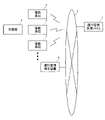
- FIG. 9 is a diagram for explaining the operation management support system 1 according to the embodiment.
- the operation management support system 1 includes a processing unit 11 , a storage unit 12 and a communication unit 13 .
- the communication unit 13 is a communication interface for connecting to the network 5 by wire or wirelessly.
- the processing unit 11 includes a travel data acquisition unit 111 , a corrected SOC calculation unit 112 , a charge/discharge recommendation determination unit 113 and a battery management information generation unit 114 .
- the functions of the processing unit 11 can be realized by cooperation of hardware resources and software resources, or only by hardware resources.
- CPU, ROM, RAM, GPU, ASIC, FPGA, and other LSIs can be used as hardware resources.
- Programs such as operating systems and applications can be used as software resources.
- the storage unit 12 includes a travel data holding unit 121 and a battery management information holding unit 122.
- the storage unit 12 includes non-volatile recording media such as HDD and SSD, and stores various data.
- the travel data acquisition unit 111 acquires travel data from each electric vehicle 3 via the network 5 and accumulates it in the travel data storage unit 121 .
- the corrected SOC calculator 112 calculates the lower limit SOC by subtracting the voltage margin from the SOCv based on the OCV method. Corrected SOC calculator 112 calculates an SOC error by subtracting the lower limit SOC from the presented SOC. It is desirable to calculate the SOC error when the reliability of the pause time is equal to or greater than a set value (eg, 0.67).
- the SOCv and the presented SOC based on the OCV method may be obtained from the vehicle control unit 30 of the electric vehicle 3, or may be calculated by the operation management support system 1 side.
- the operation management support system 1 performs the calculation, it is necessary to prepare the SOC-OCV curves of the cells E1-En included in the battery pack 41 mounted on each electric vehicle 3.
- FIG. The SOC-OCV curve may be prepared based on battery manufacturer's catalog values, or may be generated based on battery data collected from each electric vehicle 3 . In the latter case, the SOC-OCV curve may be generated for each electric vehicle 3, or the SOC-OCV curve may be generated for each vehicle type.
- FIG. 10 is a diagram showing specific examples of SOCv, lower limit SOC, and SOC error based on the OCV method.
- Corrected SOC calculator 112 calculates a corrected SOC by subtracting the SOC error from the presented SOC.
- the charging/discharging recommendation determination unit 113 recommends charging when the corrected SOC is less than the low SOC threshold (20% in FIG. 10), and recommends discharging when the corrected SOC is equal to or higher than the low SOC threshold.
- the battery management information generation unit 114 generates battery management information for each battery pack 41 mounted on each electric vehicle 3 and stores it in the battery management information holding unit 122 .
- FIG. 11 is a diagram showing a format example of battery management information.
- vehicle ID vehicle ID
- message recommended charge/recommended discharge
- presented SOC presented SOC
- corrected SOC corrected SOC
- reliability of presented SOC and reliability of pause time
- the operation manager of the delivery company can refer to the battery management information of the multiple electric vehicles 3 owned by the company, generated by the operation management support system 1 from the operation management terminal device 2.
- the operation manager can create a delivery plan and a charging plan based on the battery management information of the plurality of electric vehicles 3 .
- the operation manager urges the driver of the electric vehicle 3, which is recommended for charging, to quickly charge the vehicle.
- the operation manager creates a delivery plan and a charging plan for each electric vehicle 3 so that the SOC of the battery pack 41 of each electric vehicle 3 is in the high reliability region and the vehicle is stopped for a long time. That is, the operation manager prepares a delivery plan or a charging plan so that the predicted SOC value after completion of delivery or after completion of charging falls within the high reliability region. Note that the predicted SOC value after completion of delivery or after completion of charging is calculated in consideration of the SOC error described above.
- the delivery plan and the charging plan may be automatically created by a predetermined operation management program.
- the operation management program may be installed in the operation management terminal device 2 or may be installed in the operation management support system 1 . In the latter case, the operation management terminal device 2 can download from the operation management support system 1 the operation management table of the plurality of electric vehicles 3 owned by the company.
- FIG. 12 is a diagram for explaining an example of a basic algorithm for operation management.
- 0-20% is set in the low SOC region.
- the electric vehicle 3 whose SOC of the battery pack 41 is in the low SOC region requires charging. At that time, the charging rate and charging time are determined so that the SOC after charging is completed falls within the high reliability region.
- the delivery route is determined so that the SOC after the completion of delivery falls within the high reliability range.
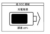
- FIGS. 13A-13C show display examples of the remaining battery level displayed on the operation management terminal device 2.
- FIG. 13A shows a display example when the remaining battery level reliability is in the normal region
- FIG. 13B shows a display example when the remaining battery level reliability is in the high reliability region
- FIG. 13C shows a display example when the remaining battery level reliability is in the high reliability region. is in the low SOC region.
- the discharge recommendation/charge recommendation and the maximum error between the suggested SOC and SOCv are displayed.
- FIG. 14 is a flowchart showing the flow of recommended discharge/recommended charge determination processing for the battery pack 41 mounted on the electric vehicle 3 by the operation management support system 1 according to the embodiment.
- the corrected SOC calculator 112 calculates the lower limit SOC by subtracting the voltage margin (maximum downward offset error of the voltage sensor) from the SOCv based on the OCV method (S10).
- the correction SOC calculation unit 112 subtracts the lower limit SOC from the presentation SOC calculated to be presented in the vehicle to obtain an SOC error.
- S12 The corrected SOC calculator 112 calculates a corrected SOC by subtracting the SOC error from the presented SOC (S13).
- the charge/discharge recommendation determination unit 113 compares the SOC error and the low SOC threshold (eg, 20%) (S14). If the SOC error is greater than or equal to the low SOC threshold (Y in S14), the charging/discharging recommendation determining unit 113 determines that the target electric vehicle 3 should be discharged (S15). If the SOC error is less than the low SOC threshold (N of S14), the charging/discharging recommendation determination unit 113 determines that charging of the target electric vehicle 3 is recommended (S16).
- the low SOC threshold eg, 20%
- step S12 While monitoring the remaining amount of the battery pack 41 of the electric vehicle 3 continues (N of S17), the process proceeds to step S12, and the processes of steps S12 to S16 are repeatedly executed. It should be noted that, as described above, the presented SOC changes according to the length of the pause time.
- the user can grasp and reset the SOC error in daily operation. You can have them learn naturally. Specifically, in areas where the slope of the SOC-OCV curve is large (high reliability area of SOC), by displaying the battery level indicator in a conspicuous color, it is possible to stop the vehicle for a long time in a non-flat area of the SOC-OCV curve. Alternatively, the user can be reminded to park.
- SOCv is SOCi, suggested SOC, FCC, ⁇ SOCv, cruising range coefficient, parameters necessary for calculating cruising range (see above (formula 1)-(formula 7)), so if the accuracy of SOCv is high, these parameters accuracy is also increased. Conversely, if the accuracy of SOCv is low, the accuracy of these parameters will also be low.
- the operation manager of the delivery company of quantitative and specific battery management information (for example, SOC reliability, SOC error, recommended charge/recommended discharge). Sudden shortage of electricity can be avoided by prompting charging when the SOC is low. If the SOC is not low, running (discharging) to the low SOC region can be encouraged. This improves the accuracy of operation management and contributes to the efficiency of delivery operations.
- quantitative and specific battery management information for example, SOC reliability, SOC error, recommended charge/recommended discharge.
- the above SOC-OCV curve depends on temperature and SOH. Therefore, it is desirable to use the SOC-OCV curve corrected using the temperature map and the SOH map. The same applies to the polarization convergence curve.
- the display control unit 313 causes the display unit 38 to display the remaining battery level pictogram in a darker color as the reliability of the presented SOC is higher.
- the size of the remaining battery level pictogram may be increased as the reliability of the presented SOC is higher.
- the higher the reliability of the presented SOC the faster the remaining battery level pictograph may blink.
- the higher the reliability of the presented SOC the denser the pattern of the remaining battery level pictogram may be.
- a mark (a good mark or a bad mark) indicating the reliability of the remaining battery level may be displayed around the display of the remaining battery level.
- the battery remaining amount reliability may be displayed as a numerical value around the battery remaining amount display.
- FIGS. 15A and 15B show another display example of the remaining battery level displayed on the display unit 38 of the electric vehicle 3.
- FIG. In this display example the SOC is displayed with a bar in units of x%.
- a maximum of 10 bars are displayed in 10% SOC increments, and one bar increases or decreases each time the SOC increases or decreases by 10%. That is, the number of bars changes according to the current presented SOC, and the display color of each bar does not change for elements other than the current presented SOC.
- the display color of each bar is based on the representative value (e.g., average value) of the remaining battery level reliability in each SOC section in x% increments, and the high reliability threshold and low reliability threshold values shown in FIG. is determined by applying
- the electric vehicle 3 is assumed to be a four-wheeled electric vehicle using the inverter 35 .
- it may be an electric motorcycle (electric scooter) or an electric bicycle.
- Electric vehicles include not only full-standard electric vehicles but also low-speed electric vehicles such as golf carts and land cars used in shopping malls, entertainment facilities, and the like.
- the remaining battery level notification according to the present disclosure can also be applied to devices other than the electric vehicle 3, in which the battery pack 41 is mounted.
- it can be applied to electronic equipment such as notebook PCs and household appliances such as vacuum cleaners.
- electronic equipment such as notebook PCs and household appliances such as vacuum cleaners.
- FCC parameters such as FCC may deviate due to use, and it is beneficial for users to naturally learn how to grasp and reset SOC errors.
- the embodiment may be specified by the following items.
- a remaining amount notification device (30) comprising:
- the user can naturally learn how to grasp and reset the SOC error during normal operation.
- the reliability determination unit (312) evaluates the reliability of the SOC indicating the remaining amount to be notified higher as the slope of the SOC-OCV curve corresponding to the SOC indicating the remaining amount to be notified is larger.
- the notification control unit (313, 314) is characterized in that the higher the reliability of the determined SOC, the more conspicuously the remaining amount of the secondary battery (41) is displayed or output by voice.
- the remaining amount notification device (30) according to item 2.
- the notification control unit (313, 314) detects the remaining amount of the secondary battery (41) when the slope of the SOC-OCV curve corresponding to the SOC indicating the remaining amount to be notified is less than a low reliability threshold. is displayed in a first color, and when the slope on the SOC-OCV curve is equal to or higher than the high reliability threshold, the remaining amount of the secondary battery (41) is displayed in a second color, and on the SOC-OCV curve is greater than or equal to the low reliability threshold and less than the high reliability threshold, the remaining capacity of the secondary battery (41) is displayed in a gradation color between the first color and the second color.
- the remaining amount notification device (30) according to item 2 or 3, characterized in that it controls to
- the notification control unit (313, 314) determines that the remaining amount of the secondary battery (41) is the first Item 2, wherein control is performed so that the remaining amount of the secondary battery (41) is displayed in a second color when the slope of the SOC-OCV curve is equal to or greater than the threshold value. 3 or the remaining amount notification device (30) according to 3.
- the SOC indicating the remaining amount to be notified is calculated by weighted average of the SOC calculated by the current integration method and the SOC calculated by the OCV method, and the device (3) 6.
- a remaining amount notification method for notifying the remaining amount of a secondary battery (41) mounted in a device (3) The slope of the SOC-OCV curve of the secondary battery (41) corresponding to the SOC indicating the reliability of the SOC indicating the remaining amount of the secondary battery (41) to be notified to the user of the device (3). a step of determining based on a step of controlling so that the remaining amount of the secondary battery (41) is notified in a notification mode based on the determined reliability of the SOC;
- a remaining amount notification method comprising:
- the user can naturally learn how to grasp and reset the SOC error during normal operation.
- a remaining amount notification program for notifying the remaining amount of a secondary battery (41) mounted in a device (3) The slope of the SOC-OCV curve of the secondary battery (41) corresponding to the SOC indicating the reliability of the SOC indicating the remaining amount of the secondary battery (41) to be notified to the user of the device (3). and the process of judging based on a process of controlling so that the remaining amount of the secondary battery (41) is notified in a notification mode based on the determined reliability of the SOC;
- the user can naturally learn how to grasp and reset the SOC error during normal operation.
Abstract
Description
電流積算法は、充放電時間が長くなるにつれて、電流測定部45の測定誤差が累積していく。一方、OCV法は、電圧測定部43の測定誤差および分極電圧による誤差の影響を受ける。そこで電池制御部46は下記(式2)に示すように、電流積算法により推定されたSOCiと、OCV法により推定されたSOCvを加重平均してSOCを推定してもよい。
xは寄与度を示し、たとえば、充放電時に1に近づき、休止時に0に近づくように設定される。なお、充放電時のSOCiを、SOCvを用いた加重平均以外の方法で補正し、充放電時のSOCとしてもよい。
SOHは、初期のFCCに対する現在のFCCの比率で規定され、数値が低いほど(0%に近いほど)劣化が進行していることを示す。電池制御部46は下記(式4)に示すように、初期のFCCと現在のFCCをもとにSOHを推定することができる。
電池制御部46は、複数のセルE1-EnのSOC、FCCおよびSOHをもとに、電池パック41のSOC、FCCおよびSOHを推定する。電池制御部46は、各セルE1-Enと電池パック41の電圧、電流、温度、SOC、FCCおよびSOHを、車載ネットワークを介して車両制御部30に送信する。
航続距離係数=Δ走行距離/ΔSOCv ・・・(式6)
ΔSOCv=走行前のSOCv-走行後のSOCv ・・・(式7)
図4は、車両制御部30の構成を説明するための図である。車両制御部30は、処理部310および記憶部322を備える。処理部310は、SOC取得部311、信頼度判定部312、表示制御部313および音声合成部314を含む。なお、処理部310には、本実施の形態にて注目する電流残量通知処理に関連する機能ブロックのみを描いている。
図6Bに示すマップでは、走行中または充電中、OCV法により推定されたSOCvの寄与度が0になる(電流積算法により推定されたSOCiがそのまま提示SOCになる)例を示しているが、走行中または充電中も、OCV法により推定されたSOCvに一定の寄与度を持たせてもよい。
機器(3)に搭載された二次電池(41)の残量を通知する残量通知装置(30)であって、
前記機器(3)のユーザに通知すべき前記二次電池(41)の残量を示すSOCの信頼度を、当該SOCに対応する、前記二次電池(41)のSOC-OCVカーブ上の傾きをもとに判定する信頼度判定部(312)と、
判定されたSOCの信頼度に基づく通知態様で、前記二次電池(41)の残量が通知されるように制御する通知制御部(313、314)と、
を備えることを特徴とする残量通知装置(30)。
前記信頼度判定部(312)は、通知すべき残量を示すSOCに対応する、前記SOC-OCVカーブ上の傾きが大きいほど、前記通知すべき残量を示すSOCの信頼度を高く評価することを特徴とする項目1に記載の残量通知装置(30)。
前記通知制御部(313、314)は、判定されたSOCの信頼度が高いほど、目立つ態様で前記二次電池(41)の残量が表示または音声出力されるように制御することを特徴とする項目2に記載の残量通知装置(30)。
前記通知制御部(313、314)は、前記通知すべき残量を示すSOCに対応する、前記SOC-OCVカーブ上の傾きが低信頼度閾値未満のとき前記二次電池(41)の残量が第1の色で表示され、前記SOC-OCVカーブ上の傾きが高信頼度閾値以上のとき前記二次電池(41)の残量が第2の色で表示され、前記SOC-OCVカーブ上の傾きが前記低信頼度閾値以上で前記高信頼度閾値未満のとき前記二次電池(41)の残量が、前記第1の色と前記第2の色の間の階調色で表示されるように制御することを特徴とする項目2または3に記載の残量通知装置(30)。
前記通知制御部(313、314)は、前記通知すべき残量を示すSOCに対応する、前記SOC-OCVカーブ上の傾きが閾値未満のとき前記二次電池(41)の残量が第1の色で表示され、前記SOC-OCVカーブ上の傾きが前記閾値以上のとき前記二次電池(41)の残量が第2の色で表示されるように制御することを特徴とする項目2または3に記載の残量通知装置(30)。
前記機器(3)の充放電停止後、前記通知すべき残量を示すSOCは、電流積算法により算出されたSOCとOCV法により算出されたSOCの加重平均により算出され、前記機器(3)の充放電停止後からの経過時間が長くなるほど、前記OCV法により算出されたSOCの寄与度が高くなることを特徴とする項目1から5のいずれか1項に記載の残量通知装置(30)。
機器(3)に搭載された二次電池(41)の残量を通知する残量通知方法であって、
前記機器(3)のユーザに通知すべき前記二次電池(41)の残量を示すSOCの信頼度を、当該SOCに対応する、前記二次電池(41)のSOC-OCVカーブ上の傾きをもとに判定するステップと、
判定されたSOCの信頼度に基づく通知態様で、前記二次電池(41)の残量が通知されるように制御するステップと、
を有することを特徴とする残量通知方法。
機器(3)に搭載された二次電池(41)の残量を通知する残量通知プログラムであって、
前記機器(3)のユーザに通知すべき前記二次電池(41)の残量を示すSOCの信頼度を、当該SOCに対応する、前記二次電池(41)のSOC-OCVカーブ上の傾きをもとに判定する処理と、
判定されたSOCの信頼度に基づく通知態様で、前記二次電池(41)の残量が通知されるように制御する処理と、
をコンピュータに実行させることを特徴とする残量通知プログラム。
Claims (8)
- 機器に搭載された二次電池の残量を通知する残量通知装置であって、
前記機器のユーザに通知すべき前記二次電池の残量を示すSOC(State Of Charge)の信頼度を、当該SOCに対応する、前記二次電池のSOC-OCV(Open Circuit Voltage)カーブ上の傾きをもとに判定する信頼度判定部と、
判定されたSOCの信頼度に基づく通知態様で、前記二次電池の残量が通知されるように制御する通知制御部と、
を備えることを特徴とする残量通知装置。 - 前記信頼度判定部は、通知すべき残量を示すSOCに対応する、前記SOC-OCVカーブ上の傾きが大きいほど、前記通知すべき残量を示すSOCの信頼度を高く評価することを特徴とする請求項1に記載の残量通知装置。
- 前記通知制御部は、判定されたSOCの信頼度が高いほど、目立つ態様で前記二次電池の残量が表示または音声出力されるように制御することを特徴とする請求項2に記載の残量通知装置。
- 前記通知制御部は、前記通知すべき残量を示すSOCに対応する、前記SOC-OCVカーブ上の傾きが低信頼度閾値未満のとき前記二次電池の残量が第1の色で表示され、前記SOC-OCVカーブ上の傾きが高信頼度閾値以上のとき前記二次電池の残量が第2の色で表示され、前記SOC-OCVカーブ上の傾きが前記低信頼度閾値以上で前記高信頼度閾値未満のとき前記二次電池の残量が、前記第1の色と前記第2の色の間の階調色で表示されるように制御することを特徴とする請求項2または3に記載の残量通知装置。
- 前記通知制御部は、前記通知すべき残量を示すSOCに対応する、前記SOC-OCVカーブ上の傾きが閾値未満のとき前記二次電池の残量が第1の色で表示され、前記SOC-OCVカーブ上の傾きが前記閾値以上のとき前記二次電池の残量が第2の色で表示されるように制御することを特徴とする請求項2または3に記載の残量通知装置。
- 前記機器の充放電停止後、前記通知すべき残量を示すSOCは、電流積算法により算出されたSOCとOCV法により算出されたSOCの加重平均により算出され、前記機器の充放電停止後からの経過時間が長くなるほど、前記OCV法により算出されたSOCの寄与度が高くなることを特徴とする請求項1から5のいずれか1項に記載の残量通知装置。
- 機器に搭載された二次電池の残量を通知する残量通知方法であって、
前記機器のユーザに通知すべき前記二次電池の残量を示すSOC(State Of Charge)の信頼度を、当該SOCに対応する、前記二次電池のSOC-OCV(Open Circuit Voltage)カーブ上の傾きをもとに判定するステップと、
判定されたSOCの信頼度に基づく通知態様で、前記二次電池の残量が通知されるように制御するステップと、
を有することを特徴とする残量通知方法。 - 機器に搭載された二次電池の残量を通知する残量通知プログラムであって、
前記機器のユーザに通知すべき前記二次電池の残量を示すSOC(State Of Charge)の信頼度を、当該SOCに対応する、前記二次電池のSOC-OCV(Open Circuit Voltage)カーブ上の傾きをもとに判定する処理と、
判定されたSOCの信頼度に基づく通知態様で、前記二次電池の残量が通知されるように制御する処理と、
をコンピュータに実行させることを特徴とする残量通知プログラム。
Priority Applications (3)
| Application Number | Priority Date | Filing Date | Title |
|---|---|---|---|
| CN202280024821.1A CN117063074A (zh) | 2021-03-29 | 2022-02-10 | 余量通知装置、余量通知方法以及余量通知程序 |
| EP22779572.1A EP4316894A1 (en) | 2021-03-29 | 2022-02-10 | Remaining capacity notification device, remaining capacity notification method, and remaining capacity notification program |
| JP2023510602A JPWO2022209343A1 (ja) | 2021-03-29 | 2022-02-10 |
Applications Claiming Priority (2)
| Application Number | Priority Date | Filing Date | Title |
|---|---|---|---|
| JP2021-055410 | 2021-03-29 | ||
| JP2021055410 | 2021-03-29 |
Publications (1)
| Publication Number | Publication Date |
|---|---|
| WO2022209343A1 true WO2022209343A1 (ja) | 2022-10-06 |
Family
ID=83455839
Family Applications (1)
| Application Number | Title | Priority Date | Filing Date |
|---|---|---|---|
| PCT/JP2022/005380 WO2022209343A1 (ja) | 2021-03-29 | 2022-02-10 | 残量通知装置、残量通知方法、および残量通知プログラム |
Country Status (4)
| Country | Link |
|---|---|
| EP (1) | EP4316894A1 (ja) |
| JP (1) | JPWO2022209343A1 (ja) |
| CN (1) | CN117063074A (ja) |
| WO (1) | WO2022209343A1 (ja) |
Cited By (1)
| Publication number | Priority date | Publication date | Assignee | Title |
|---|---|---|---|---|
| FR3139238A1 (fr) * | 2022-08-26 | 2024-03-01 | Psa Automobiles Sa | Procede d’ajustement du courant de charge d’une batterie lithium-fer-phosphate de vehicule a propulsion electrique |
Citations (13)
| Publication number | Priority date | Publication date | Assignee | Title |
|---|---|---|---|---|
| US20010006906A1 (en) * | 1999-12-22 | 2001-07-05 | Nokia Mobile Phones Limited | Battery life indication |
| JP2004239748A (ja) * | 2003-02-06 | 2004-08-26 | Sony Ericsson Mobilecommunications Japan Inc | 残電池容量検出方法および携帯端末装置 |
| JP2009208484A (ja) * | 2008-02-29 | 2009-09-17 | Calsonic Kansei Corp | 自動車用二次電池の状態表示方法 |
| JP2010136553A (ja) * | 2008-12-05 | 2010-06-17 | Toyota Motor Corp | 電源システムおよびそれを搭載した電動車両 |
| JP2010283922A (ja) * | 2009-06-02 | 2010-12-16 | Toyota Motor Corp | 車両の制御装置 |
| JP2014025739A (ja) * | 2012-07-25 | 2014-02-06 | Sanyo Electric Co Ltd | 電池状態推定装置 |
| WO2014020643A1 (ja) * | 2012-07-31 | 2014-02-06 | 三洋電機株式会社 | 制御方法およびそれを利用した制御装置 |
| JP2015038437A (ja) | 2013-08-19 | 2015-02-26 | 株式会社Gsユアサ | 充電状態信頼性判定装置、充電状態信頼性判定方法 |
| WO2018012364A1 (ja) * | 2016-07-13 | 2018-01-18 | 株式会社 村田製作所 | 組電池回路、容量係数検出方法、および容量係数検出プログラム |
| JP2018063115A (ja) * | 2016-10-11 | 2018-04-19 | トヨタ自動車株式会社 | 二次電池の充電状態推定システム |
| JP2020061824A (ja) * | 2018-10-05 | 2020-04-16 | 本田技研工業株式会社 | 診断装置、診断方法、及びプログラム |
| JP2020064030A (ja) * | 2018-10-19 | 2020-04-23 | トヨタ自動車株式会社 | 表示装置及びそれを備える車両 |
| WO2020170964A1 (ja) * | 2019-02-18 | 2020-08-27 | 株式会社Gsユアサ | 蓄電装置、抵抗器の温度調整方法 |
-
2022
- 2022-02-10 JP JP2023510602A patent/JPWO2022209343A1/ja active Pending
- 2022-02-10 WO PCT/JP2022/005380 patent/WO2022209343A1/ja active Application Filing
- 2022-02-10 EP EP22779572.1A patent/EP4316894A1/en active Pending
- 2022-02-10 CN CN202280024821.1A patent/CN117063074A/zh active Pending
Patent Citations (14)
| Publication number | Priority date | Publication date | Assignee | Title |
|---|---|---|---|---|
| US20010006906A1 (en) * | 1999-12-22 | 2001-07-05 | Nokia Mobile Phones Limited | Battery life indication |
| JP2004239748A (ja) * | 2003-02-06 | 2004-08-26 | Sony Ericsson Mobilecommunications Japan Inc | 残電池容量検出方法および携帯端末装置 |
| JP2009208484A (ja) * | 2008-02-29 | 2009-09-17 | Calsonic Kansei Corp | 自動車用二次電池の状態表示方法 |
| JP2010136553A (ja) * | 2008-12-05 | 2010-06-17 | Toyota Motor Corp | 電源システムおよびそれを搭載した電動車両 |
| JP2010283922A (ja) * | 2009-06-02 | 2010-12-16 | Toyota Motor Corp | 車両の制御装置 |
| JP2014025739A (ja) * | 2012-07-25 | 2014-02-06 | Sanyo Electric Co Ltd | 電池状態推定装置 |
| WO2014020643A1 (ja) * | 2012-07-31 | 2014-02-06 | 三洋電機株式会社 | 制御方法およびそれを利用した制御装置 |
| JP2015038437A (ja) | 2013-08-19 | 2015-02-26 | 株式会社Gsユアサ | 充電状態信頼性判定装置、充電状態信頼性判定方法 |
| JP2017083474A (ja) | 2013-08-19 | 2017-05-18 | 株式会社Gsユアサ | 充電状態信頼性判定装置、充電状態信頼性判定方法 |
| WO2018012364A1 (ja) * | 2016-07-13 | 2018-01-18 | 株式会社 村田製作所 | 組電池回路、容量係数検出方法、および容量係数検出プログラム |
| JP2018063115A (ja) * | 2016-10-11 | 2018-04-19 | トヨタ自動車株式会社 | 二次電池の充電状態推定システム |
| JP2020061824A (ja) * | 2018-10-05 | 2020-04-16 | 本田技研工業株式会社 | 診断装置、診断方法、及びプログラム |
| JP2020064030A (ja) * | 2018-10-19 | 2020-04-23 | トヨタ自動車株式会社 | 表示装置及びそれを備える車両 |
| WO2020170964A1 (ja) * | 2019-02-18 | 2020-08-27 | 株式会社Gsユアサ | 蓄電装置、抵抗器の温度調整方法 |
Cited By (1)
| Publication number | Priority date | Publication date | Assignee | Title |
|---|---|---|---|---|
| FR3139238A1 (fr) * | 2022-08-26 | 2024-03-01 | Psa Automobiles Sa | Procede d’ajustement du courant de charge d’une batterie lithium-fer-phosphate de vehicule a propulsion electrique |
Also Published As
| Publication number | Publication date |
|---|---|
| EP4316894A1 (en) | 2024-02-07 |
| JPWO2022209343A1 (ja) | 2022-10-06 |
| CN117063074A (zh) | 2023-11-14 |
Similar Documents
| Publication | Publication Date | Title |
|---|---|---|
| US11772512B2 (en) | Vehicle power supply system and vehicle dispatch system | |
| WO2016158396A1 (ja) | 電池制御装置、および電動車両システム | |
| US20220289065A1 (en) | Management system, management program, and electric vehicle | |
| WO2021166465A1 (ja) | 演算システム、電池特性推定方法、及び電池特性推定プログラム | |
| JP7373805B2 (ja) | 情報処理システム、制御装置、及び車両用電源システム | |
| US11975732B2 (en) | In-vehicle notification device, notification program, and calculation device | |
| US20130002207A1 (en) | Method for Calculating an Electric Current Provided by a Rechargeable Energy Storage System and Related Methods, Apparatuses, and Systems | |
| WO2022209343A1 (ja) | 残量通知装置、残量通知方法、および残量通知プログラム | |
| CN114730924A (zh) | 电池信息管理装置、电池信息管理方法以及电池信息管理系统 | |
| WO2022024847A1 (ja) | 演算システム、電池の劣化予測方法、及び電池の劣化予測プログラム | |
| WO2021005969A1 (ja) | 管理装置、及び車両用電源システム | |
| WO2023176102A1 (ja) | 電池状態分析システム、電池状態分析方法、及び電池状態分析プログラム | |
| WO2023120186A1 (ja) | 電池状態分析システム、電池状態分析方法、および電池状態分析プログラム | |
| WO2023188772A1 (ja) | 電池分析システム、電池分析方法および電池分析プログラム | |
| WO2022009696A1 (ja) | 演算システム、電池の検査方法、及び電池の検査プログラム | |
| WO2022024848A1 (ja) | 電池管理装置、演算システム、電池の劣化予測方法、及び電池の劣化予測プログラム | |
| WO2023136202A1 (ja) | 電池異常検出システム、電池異常検出方法、及び電池異常検出プログラム | |
| WO2023145407A1 (ja) | 電池異常検出システム、電池異常検出方法、及び電池異常検出プログラム | |
| US20230391221A1 (en) | Computation system, charging plan creation program, and discharging plan creation program | |
| WO2023026743A1 (ja) | 劣化判定システム、劣化判定方法、および劣化判定プログラム | |
| US20240083283A1 (en) | Battery abnormality prediction notification system, battery abnormality prediction system, battery abnormality prediction method, and non-transitory recording medium storing battery abnormality prediction program | |
| WO2024084802A1 (ja) | データ補間システム、データ補間方法、及びデータ補間プログラム | |
| WO2024084803A1 (ja) | データ補間システム、データ補間方法、及びデータ補間プログラム |
Legal Events
| Date | Code | Title | Description |
|---|---|---|---|
| 121 | Ep: the epo has been informed by wipo that ep was designated in this application |
Ref document number: 22779572 Country of ref document: EP Kind code of ref document: A1 |
|
| ENP | Entry into the national phase |
Ref document number: 2023510602 Country of ref document: JP Kind code of ref document: A |
|
| WWE | Wipo information: entry into national phase |
Ref document number: 18551663 Country of ref document: US |
|
| WWE | Wipo information: entry into national phase |
Ref document number: 202280024821.1 Country of ref document: CN |
|
| WWE | Wipo information: entry into national phase |
Ref document number: 2022779572 Country of ref document: EP |
|
| NENP | Non-entry into the national phase |
Ref country code: DE |
|
| ENP | Entry into the national phase |
Ref document number: 2022779572 Country of ref document: EP Effective date: 20231030 |