WO2022209285A1 - 超純水製造システム - Google Patents
超純水製造システム Download PDFInfo
- Publication number
- WO2022209285A1 WO2022209285A1 PCT/JP2022/004467 JP2022004467W WO2022209285A1 WO 2022209285 A1 WO2022209285 A1 WO 2022209285A1 JP 2022004467 W JP2022004467 W JP 2022004467W WO 2022209285 A1 WO2022209285 A1 WO 2022209285A1
- Authority
- WO
- WIPO (PCT)
- Prior art keywords
- ultrapure water
- membrane device
- monolithic
- production system
- exchanger
- Prior art date
- Legal status (The legal status is an assumption and is not a legal conclusion. Google has not performed a legal analysis and makes no representation as to the accuracy of the status listed.)
- Ceased
Links
Images






Classifications
-
- B—PERFORMING OPERATIONS; TRANSPORTING
- B01—PHYSICAL OR CHEMICAL PROCESSES OR APPARATUS IN GENERAL
- B01D—SEPARATION
- B01D61/00—Processes of separation using semi-permeable membranes, e.g. dialysis, osmosis or ultrafiltration; Apparatus, accessories or auxiliary operations specially adapted therefor
- B01D61/14—Ultrafiltration; Microfiltration
- B01D61/145—Ultrafiltration
-
- B—PERFORMING OPERATIONS; TRANSPORTING
- B01—PHYSICAL OR CHEMICAL PROCESSES OR APPARATUS IN GENERAL
- B01D—SEPARATION
- B01D61/00—Processes of separation using semi-permeable membranes, e.g. dialysis, osmosis or ultrafiltration; Apparatus, accessories or auxiliary operations specially adapted therefor
- B01D61/42—Electrodialysis; Electro-osmosis ; Electro-ultrafiltration; Membrane capacitive deionization
- B01D61/44—Ion-selective electrodialysis
- B01D61/46—Apparatus therefor
- B01D61/463—Apparatus therefor comprising the membrane sequence AC or CA, where C is a cation exchange membrane
-
- B—PERFORMING OPERATIONS; TRANSPORTING
- B01—PHYSICAL OR CHEMICAL PROCESSES OR APPARATUS IN GENERAL
- B01D—SEPARATION
- B01D61/00—Processes of separation using semi-permeable membranes, e.g. dialysis, osmosis or ultrafiltration; Apparatus, accessories or auxiliary operations specially adapted therefor
- B01D61/58—Multistep processes
-
- B—PERFORMING OPERATIONS; TRANSPORTING
- B01—PHYSICAL OR CHEMICAL PROCESSES OR APPARATUS IN GENERAL
- B01D—SEPARATION
- B01D69/00—Semi-permeable membranes for separation processes or apparatus characterised by their form, structure or properties; Manufacturing processes specially adapted therefor
-
- C—CHEMISTRY; METALLURGY
- C02—TREATMENT OF WATER, WASTE WATER, SEWAGE, OR SLUDGE
- C02F—TREATMENT OF WATER, WASTE WATER, SEWAGE, OR SLUDGE
- C02F1/00—Treatment of water, waste water, or sewage
- C02F1/30—Treatment of water, waste water, or sewage by irradiation
- C02F1/32—Treatment of water, waste water, or sewage by irradiation with ultraviolet light
-
- C—CHEMISTRY; METALLURGY
- C02—TREATMENT OF WATER, WASTE WATER, SEWAGE, OR SLUDGE
- C02F—TREATMENT OF WATER, WASTE WATER, SEWAGE, OR SLUDGE
- C02F1/00—Treatment of water, waste water, or sewage
- C02F1/42—Treatment of water, waste water, or sewage by ion-exchange
-
- C—CHEMISTRY; METALLURGY
- C02—TREATMENT OF WATER, WASTE WATER, SEWAGE, OR SLUDGE
- C02F—TREATMENT OF WATER, WASTE WATER, SEWAGE, OR SLUDGE
- C02F1/00—Treatment of water, waste water, or sewage
- C02F1/44—Treatment of water, waste water, or sewage by dialysis, osmosis or reverse osmosis
- C02F1/444—Treatment of water, waste water, or sewage by dialysis, osmosis or reverse osmosis by ultrafiltration or microfiltration
-
- C—CHEMISTRY; METALLURGY
- C02—TREATMENT OF WATER, WASTE WATER, SEWAGE, OR SLUDGE
- C02F—TREATMENT OF WATER, WASTE WATER, SEWAGE, OR SLUDGE
- C02F9/00—Multistage treatment of water, waste water or sewage
-
- C—CHEMISTRY; METALLURGY
- C02—TREATMENT OF WATER, WASTE WATER, SEWAGE, OR SLUDGE
- C02F—TREATMENT OF WATER, WASTE WATER, SEWAGE, OR SLUDGE
- C02F1/00—Treatment of water, waste water, or sewage
- C02F1/44—Treatment of water, waste water, or sewage by dialysis, osmosis or reverse osmosis
-
- C—CHEMISTRY; METALLURGY
- C02—TREATMENT OF WATER, WASTE WATER, SEWAGE, OR SLUDGE
- C02F—TREATMENT OF WATER, WASTE WATER, SEWAGE, OR SLUDGE
- C02F1/00—Treatment of water, waste water, or sewage
- C02F1/42—Treatment of water, waste water, or sewage by ion-exchange
- C02F2001/422—Treatment of water, waste water, or sewage by ion-exchange using anionic exchangers
-
- C—CHEMISTRY; METALLURGY
- C02—TREATMENT OF WATER, WASTE WATER, SEWAGE, OR SLUDGE
- C02F—TREATMENT OF WATER, WASTE WATER, SEWAGE, OR SLUDGE
- C02F1/00—Treatment of water, waste water, or sewage
- C02F1/42—Treatment of water, waste water, or sewage by ion-exchange
- C02F2001/425—Treatment of water, waste water, or sewage by ion-exchange using cation exchangers
-
- C—CHEMISTRY; METALLURGY
- C02—TREATMENT OF WATER, WASTE WATER, SEWAGE, OR SLUDGE
- C02F—TREATMENT OF WATER, WASTE WATER, SEWAGE, OR SLUDGE
- C02F2103/00—Nature of the water, waste water, sewage or sludge to be treated
- C02F2103/02—Non-contaminated water, e.g. for industrial water supply
- C02F2103/04—Non-contaminated water, e.g. for industrial water supply for obtaining ultra-pure water
Definitions
- the present invention relates to an ultrapure water production system capable of producing ultrapure water with particularly high purity and supplying the ultrapure water to a point of use (POU).
- POU point of use
- ultrapure water is used for various purposes such as cleaning.
- raw water such as river water, groundwater, or industrial water is first pretreated by a pretreatment system, and then supplied to a primary pure water system to produce pure water (also called primary pure water). call).
- the primary pure water is supplied to the secondary pure water system (also called a subsystem) to further increase the purity to obtain ultrapure water, and the ultrapure water obtained in the secondary pure water system is its point of use.
- the position where ultrapure water is received in the equipment using ultrapure water is also called an entry point (POE).
- the point of use of ultrapure water includes the point of entry (POE) of ultrapure water.
- the secondary pure water system is configured so that ultrapure water that has not been supplied to the point of use is returned to the inlet side of the secondary pure water system. That is, in the secondary pure water system, ultrapure water is constantly circulated, and the ultrapure water undergoes further purification treatment due to the circulation.
- an ultraviolet oxidation device (UV), a non-regenerative ion exchange device (CP; cartridge polisher), a membrane deaerator ( MD) and ultrafiltration membrane device (UF) are connected in this order.
- a circulation pipe for returning the ultrapure water to the tank is provided from the outlet side of the ultrafiltration membrane device, and a supply pipe for supplying the ultrapure water to the use point is provided by branching from the circulation pipe.
- the ultrapure water production system includes a secondary pure water system in which ultrapure water not supplied to the point of use is always circulated, and the secondary pure water system includes at least an ultrafiltration membrane device, It means that the supply pipe for supplying ultrapure water to the point of use branches downstream of the ultrafiltration membrane device.
- the ultrafiltration membrane device When ultrapure water is used in the manufacturing process of semiconductor devices and liquid crystal devices, the microparticles contained in the ultrapure water directly cause a decrease in device manufacturing yield. It is necessary to strictly control the number or concentration of fine particles contained in a volume of ultrapure water. The reason why the ultrafiltration membrane device is arranged at or near the final stage in the secondary pure water system as described above is to reduce the amount of fine particles in the ultrapure water. In recent years, however, quality requirements for ultrapure water have become more and more stringent, and there is a need to perform treatment to further increase the purity of ultrapure water obtained by a secondary pure water system. For example, there is a need to remove components that elute from the ultrafiltration membrane device itself.
- a booster pump or a booster pump is installed in the interior or in the piping from the secondary pure water system to the semiconductor device manufacturing equipment.
- a booster pump or the like it becomes necessary to remove fine particles generated by the pump from the ultrapure water.
- Patent Document 1 discloses that the raw water used for ultrapure water production is any of boron, arsenic, aluminum, titanium, chromium, iron, copper, zinc, tin, vanadium, gallium and lead. at least the monolithic organic porous material in the treatment path in the secondary pure water system or in the transfer path from the secondary pure water system to the ultrapure water point of use, if it contains metallic impurities of one or more elements It discloses installing an ion-exchanger-packed module that is packed with quality anion-exchangers.
- Patent Document 1 The technology described in Patent Document 1 is intended to remove specific metal impurities contained in raw water, and Patent Document 1 does not describe the advanced removal of fine particles. There is a demand for a technology for producing and supplying ultrapure water from which fine particles are highly removed, including fine particles eluted from ultrafiltration membranes and booster pumps.
- the purpose of the present invention is to provide an ultrapure water production system capable of producing ultrapure water from which fine particles have been removed to a high degree and supplying it to points of use.
- the ultrapure water production system is positioned downstream of the ultrafiltration membrane device in an ultrapure water supply line connected to a point of use and supplying ultrapure water to the point of use. and a microfiltration membrane device provided at a position downstream of the first organic porous ion exchanger in the ultrapure water supply line.
- the ultrapure water production system of the present invention includes an ultrafiltration membrane device and an ultrafiltration membrane device in an ultrapure water supply line connected to a point of use and supplying ultrapure water to the point of use.
- a first organic porous ion exchanger provided at a position between the pump provided at an upstream position and a position downstream of the ultrafiltration membrane device in the ultrapure water supply line. and a microfiltration membrane device.
- an ultrapure water production system capable of producing ultrapure water from which fine particles are highly removed and supplying the ultrapure water to points of use.
- FIG. 4 is a diagram showing the configuration of another example of the ultrapure water production system;
- FIG. 4 is a diagram showing the configuration of another example of the ultrapure water production system;
- BRIEF DESCRIPTION OF THE DRAWINGS It is a figure which shows the structure of the ultrapure water production system of one embodiment of this invention.
- FIG. 4 is a diagram showing the configuration of another example of the ultrapure water production system;
- FIG. 4 is a diagram showing the configuration of another example of the ultrapure water production system;
- FIG. 4 is a diagram showing the configuration of another example of the ultrapure water production system;
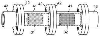
- FIG. 4 is a diagram showing an installation example of an organic porous ion exchanger.
- FIG. 4 is a diagram showing the configuration of another example of the ultrapure water production system;
- FIG. 4 is a diagram showing the configuration of another example of the ultrapure water production system;
- 1 is a diagram showing the configuration of an apparatus used in Example 1.
- FIG. 4 is a graph showing the results of Example 1.
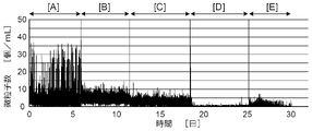
- FIG. 4 is a graph showing the results of Example 1.
- FIG. 4 is a graph showing the results of Example 1.
- the ultrapure water production system shown in FIG. 1 is configured as a general secondary pure water system (subsystem) used for producing ultrapure water, and is supplied from a primary pure water system (not shown).
- HE heat exchanger
- UV ultraviolet oxidation device
- CP non-regenerative ion exchange device
- MD membrane deaerator
- UF ultrafiltration membrane device
- the heat exchanger 12, the ultraviolet oxidation device 13, the non-regenerative ion exchange device 14, the membrane degassing device 15 and the ultrafiltration membrane device 16 are connected to the outlet of the tank 11 in this order.
- the non-regenerative ion exchange device 14 is filled with bead-like or granular ion-exchange resin.
- the membrane degassing device 15 may not be provided.
- a circulation pipe 20 is connected to the outlet of the ultrafiltration membrane device 16 to return the ultrapure water that has passed through the ultrafiltration membrane device 16 to the tank 11.
- a supply pipe 21 branches off from the circulation pipe 20 for supplying ultrapure water to the ultrapure water inlet point of . Therefore, the supply pipe 21 branches from the downstream side of the ultrafiltration membrane device 16 .
- the supply pipe 21 is also called distribution.
- a plurality of supply pipes 21 are branched from the circulation pipe 20 .
- the ultrapure water that has not been supplied to the point of use is always circulated to the tank 11 upstream of the ultrafiltration membrane device 16 .
- the ultrapure water production system according to the present invention is a general ultrapure water production system as shown in FIG. Furthermore, by installing a microfiltration membrane device downstream of at least one of the organic porous ion exchangers, ultrapure water from which fine particles, including fine particles generated in the ultrafiltration membrane device and the booster pump, are highly removed. I am trying to get it.
- General ion exchange resins are in the form of beads or granules with a diameter of several mm or less, but organic porous ion exchangers have a skeleton made of an organic polymer, as described in Patent Document 1.
- the porous macropores are continuous to form a continuous macropore structure, and ion-exchange groups are introduced into the organic polymer that serves as the skeleton.
- Organic porous ion exchangers are also called monolithic organic porous ion exchangers or monolithic ion exchangers. ), and an organic porous ion exchanger, which is a cation exchanger, is called a monolithic cation exchanger (CEM: Cation Exchange Monolith).
- CEM Cation Exchange Monolith
- the organic porous ion exchanger can be molded into any shape and size. Since the organic porous ion exchanger has a continuous macropore structure, it is formed in the shape of a sponge having elasticity, and the water to be treated can pass through the inside thereof, and ion exchange with respect to the water to be treated occurs during the passage of the water.
- An example of a method for producing an organic porous ion exchanger, ie, a monolithic organic porous ion exchanger, is described in US Pat.
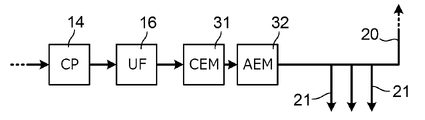
- FIG. 2 is a diagram showing the essential parts of such an ultrapure water production system.
- the ultrapure water production system shown here is the ultrapure water production system shown in FIG. They are arranged in this order, and FIG. 2 shows the positions where the monolithic cation exchanger 31 and the monolithic anion exchanger 32 are arranged in the ultrapure water production system and their vicinity. 2 to 7 do not depict the membrane degassing device 15 provided between the outlet of the non-regenerative ion exchange device 14 and the inlet of the ultrafiltration membrane device 16 in the ultrapure water production system.
- the position where the supply pipe 21 branches off from the circulation pipe 20 is downstream of the monolithic anion exchanger 32, which is the downstream ion exchanger.
- the monolithic cation exchanger 31 and the monolithic anion exchanger 32 are arranged in this way, fine particles generated in the ultrafiltration membrane device 16, for example, the adhesive used in the joints in the ultrafiltration membrane device 16 It is possible to remove fine particles generated from such as.
- a bead-like or granular ion-exchange resin is used instead of a monolithic ion-exchanger, it is necessary to use a metal mesh or the like in order to prevent the ion-exchange resin from flowing out.
- monolithic ion exchangers when a monolithic ion exchanger is used, a mesh or the like is not required, so there is no fear of generation of fine particles from the mesh.
- monolithic ion exchangers have a higher adsorption rate for ionic impurities and fine particles than bead-shaped or granular ion-exchange resins. can be achieved.
- the order of arrangement of the monolithic cation exchanger 31 and the monolithic anion exchanger 32 may be changed, or only one of the monolithic ion exchangers may be provided. At least one of the monolithic cation exchanger 31 and the monolithic anion exchanger 32 may be provided in plurality. However, in order to efficiently remove fine particles generated in the ultrafiltration membrane device 16, it is desirable to use the monolithic cation exchanger 31 on the upstream side and the monolithic anion exchanger 32 on the downstream side. Monolithic ion exchangers, or organic porous ion exchangers, are believed to be able to remove particulates by electrostatic effects.
- the monolithic anion exchanger 32 is excellent in fine particle removal performance.
- fine pores are formed on the surface of the monolithic ion exchanger, fine particles may be trapped by the pores and removed.
- the position where the monolith cation exchanger 31 and the monolith anion exchanger 32 are provided may be either the circulation pipe 20 or the supply pipe 21 .
- a monolithic ion exchanger should be installed in the path of ultrapure water from the outlet of the ultrafiltration membrane device 16 to the point of use of the ultrapure water.
- the Mooris anion exchanger 32 may be installed in the supply pipe 21 instead of the circulation pipe 20 .
- the monolithic ion exchanger is preferably installed after the booster pump.
- a line that connects the outlet of the non-regenerative ion exchanger 14 to the point of use via the supply pipe 21 and supplies ultrapure water to the point of use is referred to as an ultrapure water supply line.
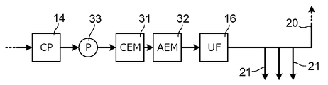
- Fig. 3 shows another example of an ultrapure water production system.
- the ultrapure water production system shown here differs from that shown in FIG. This configuration is suitable when a booster pump (P) 33 is provided upstream of the ultrafiltration membrane device 16, and in the illustrated example, monolithic cation exchanger 31 and monolithic anion exchanger
- the bodies 32 are connected in this order, and the water that has passed through the monolithic anion exchanger 32 is supplied to the ultrafiltration membrane device 16 .
- the ultrapure water circulating through the circulation pipe 20 is returned to the upstream side of the booster pump 33 . Impurities such as metal components and fine particles are generated in the booster pump 33 and become a load on the ultrafiltration membrane device 16 .
- the exchanger 32 By arranging the exchanger 32, the inflow of impurities into the ultrafiltration membrane device 16 can be reduced, and the load on the ultrafiltration membrane device 16 can be reduced.
- the monolithic ion exchanger has a smaller pressure loss when water is passed than those filled with bead-shaped or granular ion-exchange resins. be.
- the order of arrangement of the monolithic cation exchanger 31 and the monolithic anion exchanger 32 may be changed, or only one of the monolithic ion exchangers may be provided.
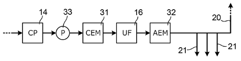
- Fig. 4 shows another example of an ultrapure water production system.
- the ultrapure water production system shown here is characterized in that the monolithic cation exchanger 31 is provided on the inlet side of the ultrafiltration membrane device 16 and the monolithic anion exchanger 32 is provided on the outlet side of the ultrafiltration membrane device 16. , is different from that shown in FIG.
- a supply pipe 21 branches off from the circulation pipe 20 downstream of the monolithic anion exchanger 32 .
- This configuration is suitable when the booster pump 33 is provided in the preceding stage of the ultrafiltration membrane device 16, and in that case, the monolithic cation exchanger 31 is arranged between the booster pump 33 and the ultrafiltration membrane device 16. be done.
- the ultrapure water circulating through the circulation pipe 20 is returned to the upstream side of the booster pump 33 .
- the monolithic cation exchanger 31 provided at the front stage of the ultrafiltration membrane device 16 mainly removes metallic impurities generated by the booster pump 33, and the monolithic anion exchanger 32 provided at the rear stage of the ultrafiltration membrane device 16 , the fine particles generated by the booster pump 33 and the ultrafiltration membrane device 16 are mainly removed.
- the monolithic ion exchanger shown in FIG. 4 is also advantageous when increasing the supply pressure of ultrapure water, since the pressure loss is small when water is passed through the monolithic ion exchanger. In the ultrapure water production system shown in FIG.
- the monolithic anion exchanger 32 is provided at any position along the ultrapure water route from the outlet of the ultrafiltration membrane device 16 to the ultrapure water point of use. Just do it. Also, in the ultrapure water production system shown in FIG. A monolithic cation exchanger 31 may be provided on the outlet side of the filtration membrane device 16 . However, from the viewpoint of removing fine particles, it is preferable to allow water to flow through the monolithic cation exchanger 31, the ultrafiltration membrane device 16, and the monolithic anion exchanger 32 in that order.
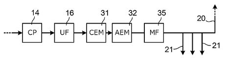
- the ultrapure water production system includes a microfiltration membrane device downstream of at least one monolithic ion exchanger, i.e., an organic porous ion exchanger, in the ultrapure water production system shown in each of FIGS.
- a microfiltration membrane device downstream of at least one monolithic ion exchanger, i.e., an organic porous ion exchanger, in the ultrapure water production system shown in each of FIGS.
- the pore size of the microfiltration membrane is, for example, 1 nm or more.
- at least one microfiltration membrane device 35 is downstream of all monolithic ion exchangers from the outlet of the ultrafiltration membrane device 16 to the ultrapure water point of use. is preferably provided in the path of ultrapure water.
- FIG. 5 an example of providing the microfiltration membrane device 35 in the circulation pipe 20 in the ultrapure water production system shown in FIG. 2 (FIG. 5) and an example of providing the microfiltration membrane device 35 in the supply pipe 21 (FIG. 6) have been described.
- FIGS When providing a booster pump for pressurization in the ultrapure water production system shown in FIGS.
- the monolithic ion exchanger provided on the secondary pure water system side including the circulation pipe 20 is Separately, a monolithic ion exchanger may also be arranged in the supply pipe 21 to remove fine particles generated from each pipe. Since the monolithic ion exchanger placed in the supply pipe 21 focuses on removing fine particles rather than metal impurities, the monolithic ion exchanger is preferred over the monolithic cation exchanger when electrostatic interactions with fine particles are considered. An anion exchanger is preferred.
- Patent Document 1 discloses filling a cartridge with a monolithic ion exchanger.
- a cartridge filled with a monolithic ion exchanger is housed inside a housing (called a cartridge housing, a filter housing, a housing column, or the like) connected to a pipe.
- the monolithic ion exchanger can be elastic and spongy, in which case the monolithic ion exchanger can be placed directly in the pipe by inserting it into the pipe.
- the material of the pipe in which the monolithic ion exchanger is arranged is not particularly limited, and the material commonly used for ultrapure water pipes is used. can be used, and metallic or non-metallic piping can be used. It is preferable to use a non-metallic pipe from the viewpoint of less elution of metal components.
- Non-metallic pipes include polypropylene (PP) pipes, polyvinyl chloride (PVC) pipes, chlorinated polyvinyl chloride (CPVC) pipes, high density polyethylene (HDPE) pipes, low density polyethylene (LDPE) pipes, polyfluoride Examples include vinylidene (PVDF) tubes, perfluoroalkoxyalkane (PFA) tubes, polytetrafluoroethylene (PTFE) tubes, and the like. Among them, it is preferable to use a pipe made of a fluororesin that has a small amount of eluted metal components and high chemical resistance. Polyvinylidene fluoride (PVDF) tubing is particularly preferred due to its excellent pressure resistance.
- PVDF polyvinylidene fluoride
- welding, gluing, and flange-fixing methods are available as methods for attaching a pipe with a monolithic ion exchanger to the ultrapure water supply line. From the viewpoint of ease of maintenance, flange-fixing is preferred. It is preferable to use Also, the material of the O-ring or gasket used for the pipe connection is not particularly limited, but it is preferable to use an O-ring made of fluororesin or fluororubber, since the elution of metal components is small. In order to perform maintenance, it is preferable that two or more pipes in which the monolithic ion exchangers are arranged are provided in parallel, as shown in FIGS. 9 and 10 which will be described later.
- the diameter of the pipe used for arranging the monolithic ion exchanger inside is preferably set according to the water flow rate to the monolithic ion exchanger, and is generally defined by JIS (Japanese Industrial Standards).
- the nominal diameter is in the range of 15A to 200A. If the pipe diameter is smaller than 15A, the number of pipes to be installed in parallel to obtain the required water flow rate becomes excessively large when the pipes having the monolithic ion exchanger installed are installed in parallel. higher cost.
- Fig. 8 shows an example in which a monolithic ion exchanger is placed inside the pipe.
- a straight pipe member 41 is provided at both ends with flanges 42 used for connection with other flanged pipes 43 (or other pipe members 41).
- a monolithic cation exchanger 31 is inserted inside the piping member 41 on the left side in the figure.
- the monolithic cation exchanger 31 is processed into a cylindrical shape having a dimension slightly larger than the inner diameter of the piping member 41 in a state where it is not pressed, and when pushed into the piping member 41 from one end of the piping member 41, the piping member 41 is is arranged inside the piping member 41 in a state of pressing the inner wall of the pipe member 41 .
- a stepped portion may be provided on the inner wall of the piping member 41 so that the monolithic cation exchanger 41 engages with the stepped portion.
- a monolithic anion exchanger 42 is inserted inside the piping member 41 on the right side of the drawing.
- the piping member 41 in which the monolithic ion exchanger is inserted is removed from the other piping 43, and then the piping member 41 in which the new monolithic ion exchanger is inserted. may be attached to another pipe 43 using the flange 42 .
- the pipes 43 on both sides may be connected by flanged pipes having no monolithic ion exchanger.
- one monolithic ion exchanger is arranged for one piping member 41, but a plurality of monolithic ion exchangers are arranged for one piping member 41.
- a plurality of monolithic cation exchangers 31 may be arranged with respect to one piping member 41, or a plurality of monolithic anion exchangers 32 may be arranged. It may be arranged in combination with the exchange body 32 .
- Monolithic ion exchangers can reduce pressure loss when water is passed through compared to those filled with bead-shaped or granular ion exchange resins. There is a case where it is desired to make the water flow differential pressure at .
- the path of water that should flow through the monolithic ion exchanger is branched into a plurality of pipes provided in parallel, and the monolithic ion What is necessary is just to provide an exchange body.
- FIG. 9 shows the ultrapure water production system shown in FIG.
- this ultrapure water production system two sets of serially connected monolithic cation exchangers 31 and monolithic anion exchangers 32 are provided in parallel by piping. The water to be filtered is diverted and the water from both monolithic anion exchangers 32 is combined and fed to the ultrafiltration membrane device 16 .
- microfiltration membrane devices 35 are also provided in parallel, and the water that has passed through the ultrafiltration membrane device 16 is distributed and supplied to the two microfiltration membrane devices 35, and passed through these microfiltration membrane devices 35. Water joins and is supplied to the supply pipe 21 after that.
- a pump such as a booster pump is provided on the upstream side of the monolithic cation exchanger 31 .
- FIG. 10 shows the ultrapure water production system shown in FIG. 4 in which a microfiltration membrane device 35 is provided downstream of the monolith anion exchanger 32.
- a pipe On the upstream side of the ultrafiltration membrane device 16, a pipe is branched into two pipes provided in parallel, and a monolithic cation exchanger 31 is provided for each branched pipe to divide the water from the upstream side, and these two The water that has passed through the two monolithic cation exchangers 31 is combined and supplied to the ultrafiltration membrane device 16 .
- the outlet pipe of the ultrafiltration membrane device 16 is also branched into two pipes, and a monolithic anion exchanger 32 is provided for each branched pipe. Divert to another pipe.
- a microfiltration membrane device 35 is provided for each of these two pipes, and the water that has passed through the two microfiltration membrane devices 35 joins, and then part of it is supplied to the supply pipe 21, and the rest is circulated. It is returned to the upstream side of monolithic cation exchanger 31 via pipe 20 .
- a pump such as a booster pump is provided on the upstream side of the monolithic cation exchanger 31 .
- the outlet water of two monolith cation exchangers 32 provided in parallel is once merged and then distributed to two microfiltration membrane devices 35, but the outlet water of the monolith cation exchanger 32 may be directly supplied to the subsequent microfiltration membrane device 35 without being merged.
- two sets of connectors are prepared in which one microfiltration membrane device 35 is connected to the outlet of one monolithic cation exchanger 32, and the two sets of connectors are arranged in parallel for use.
- the conditions for passing water through the monolithic ion exchanger are not particularly limited, but the water passing speed represented by the space velocity (SV) is preferably 20000 h ⁇ 1 or less. , more preferably 10 to 4000 h -1 , particularly preferably 600 to 4000 h -1 . Also, the water flow rate represented by linear velocity (LV) is preferably 1000 m/h or less, more preferably 500 m/h or less.
- SV space velocity
- LV linear velocity
- Example 1 The device shown in FIG. 11 was assembled.
- the device shown in FIG. the monolithic cation exchanger 31, the monolithic anion exchanger 32, the microfiltration membrane device 35 and the valve 53 in this order, the second route discharged, the flow meter 54, the microfiltration membrane device 36 and the valve 55 It is configured to be distributed to three routes, including a third route that passes in this order and is discharged. Separately from these, a measurement pipe 60 to which a particle counter (PC) 66 is connected is provided. As the particle counter 66, UltraChem 40 manufactured by Specttris was used.
- PC particle counter
- Outlet water [A] of the ultrafiltration membrane device 16, outlet water [B] of the monolithic cation exchanger 31, outlet water [C] of the monolithic anion exchanger 32, microfiltration membrane device 35 provided in the second route and the outlet water [D] of the microfiltration membrane device 36 provided in the third route and the outlet water [E] of Valves 61 to 65 are provided in respective pipes supplying to the measurement pipe 61 .
- the monolithic cation exchanger 31 and the monolithic anion exchanger 32 are monolithic cation exchangers produced according to the method described in paragraphs [0131] to [0135] of Patent Document 1 (Reference Example 1 of Patent Document 1) and A monolithic anion exchanger was used.
- Both monolithic cation exchangers and monolithic anion exchangers were used by fabricating and attaching to 150A PPG flange tubing 50 mm long ion exchanger packed cartridges filled with the monolithic ions and attached to the tubing.
- microfiltration membrane devices 35 and 36 microfiltration membranes with a pore size of 20 nm were used.
- Ultrapure water was supplied to the ultrafiltration membrane device 16, and the outlet water [A] of the ultrafiltration membrane device 16 at that time was distributed to each of the first to third channels at 30 L/min and continued to flow.
- the space velocity (SV) of water passing through each of the monolith cation exchanger 31 and the monolith anion exchanger 32 was 4000 h -1 and the linear velocity (LV) was 400 m/h.
- the outlet water [A] of the ultrafiltration membrane device 16 the outlet water [B] of the monolithic cation exchanger 31, the outlet water [C] of the monolithic anion exchanger 32, the second The outlet water [D] of the microfiltration membrane device 35 provided on the path and the outlet water [E] of the microfiltration membrane device 36 provided on the third path are sequentially sent to the measurement pipe 60 in this order, and the outlet The number of fine particles with a diameter of 40 nm or more contained in water [A] to [E] was continuously counted by a particle counter 66 .
- the number of fine particles means the number of fine particles contained in a unit volume of outlet water.
- FIG. 12A shows the measurement result of the number of fine particles.
- FIG. 12B shows the result of obtaining the moving average for 60 minutes for the result shown in FIG. 12A.
- the number of fine particles contained in the outlet water [A] of the ultrafiltration membrane device 16 was obtained for about the first six days from the start of measurement, but the number of fine particles spiked up. is frequent.
- the number of fine particles in the outlet water [B] of the monolith cation exchanger 31, that is, the water that passed through the ultrafiltration membrane device 16 and the Morris cation exchanger 31 in this order was determined.
- Outlet water "B” yielded results that averaged the fine particle counts in outlet water [A].
- the number of fine particles in the water that passed through the filtration membrane device 16, the monolithic cation exchanger 31, and the monolithic anion exchanger 32 in this order was determined.
- the outlet water [D] of the microfiltration membrane device 35 of the second route that is, the ultrafiltration membrane device 16, the Morris cation exchanger 31, and the monolithic anion exchanger 32 and microfiltration membrane device 35 in this order, the number of fine particles was determined.
- the outlet water [D] contained almost no fine particles.
- the outlet water [E] of the filtration membrane device 36 that is, the water that has passed through the ultrafiltration membrane device 16 and the microfiltration membrane device 36 in this order without passing through the organic porous ion exchanger, that is, the monolithic ion exchanger
- the number of fine particles in the outlet water [E] is also smaller than the number of fine particles in the outlet water of each monolithic ion exchanger, but the number of fine particles in the outlet water [D] of the microfiltration membrane device 35 in the second route is smaller than the number of fine particles in the outlet water [D]. A little too many.
- the number of fine particles can be reduced by sequentially passing the outlet water of the ultrafiltration membrane device 16 through the monolithic cation exchanger 31 and the monolithic anion exchanger 32. It was found that the concentration of detected microparticles can be reduced to less than 1/mL by increasing the concentration.
Landscapes
- Water Supply & Treatment (AREA)
- Engineering & Computer Science (AREA)
- Chemical & Material Sciences (AREA)
- Environmental & Geological Engineering (AREA)
- Life Sciences & Earth Sciences (AREA)
- Hydrology & Water Resources (AREA)
- Organic Chemistry (AREA)
- Chemical Kinetics & Catalysis (AREA)
- Health & Medical Sciences (AREA)
- Urology & Nephrology (AREA)
- Toxicology (AREA)
- Separation Using Semi-Permeable Membranes (AREA)
- Treatment Of Water By Ion Exchange (AREA)
Abstract
Description
図11に示す装置を組み立てた。図11に示す装置は、限外ろ過膜装置16を備えており、限外ろ過膜装置16の出口水が、弁51を介してそのまま排出される第1の経路と、流量計(FI)52、モノリスカチオン交換体31、モノリスアニオン交換体32、精密ろ過膜装置35及び弁53をこの順で通過して排出される第2の経路と、流量計54、精密ろ過膜装置36及び弁55をこの順で経過して排出される第3の経路との3つの経路に分配されるように構成されている。これらとは別に、パーティクルカウンタ(PC)66が接続する計測用配管60が設けられている。パーティクルカウンタ66としては、Specttris社製のUltraChem40を使用した。限外ろ過膜装置16の出口水[A]、モノリスカチオン交換体31の出口水[B]、モノリスアニオン交換体32の出口水[C]、第2の経路に設けられた精密ろ過膜装置35の出口水[D]及び第3の経路に設けられた精密ろ過膜装置36の出口水[E]をそれぞれ切り替えて計測用配管60に供給するために、出口水[A]~[E]を計測用配管61に供給するそれぞれの配管に弁61~65が設けられている。モノリスカチオン交換体31及びモノリスアニオン交換体32としては、特許文献1の段落[0131]~[0135](特許文献1の参考例1)に記載された方法に基づいて製造したモノリスカチオン交換体及びモノリスアニオン交換体を使用した。モノリスカチオン交換体及びモノリスアニオン交換体は、いずれも、150A PPGフランジ配管に対して長さ50mmでそのモノリス状イオンを充填させたイオン交換体充填カートリッジを製作して配管に取り付けることにより使用した。精密ろ過膜装置35,36として、精密ろ過膜の孔径が20nmのものを使用した。
12 熱交換器(HE)
13 紫外線酸化装置(UV)
14 非再生型イオン交換装置(CP)
15 膜脱気装置(MD)
16 限外ろ過膜装置(UF)
20 循環配管
21 供給配管
31 モノリスカチオン交換体(CEM)
32 モノリスアニオン交換体(AEM)
33 ブースタポンプ(P)
35,36 精密ろ過膜装置(MF)
41 配管部材
42 フランジ
43 配管
66 パーティクルカウンタ(PC)
67 全有機炭素濃度計(TOC)
Claims (10)
- ユースポイントに接続されて前記ユースポイントに超純水を供給する超純水供給ラインにおいて、限外ろ過膜装置の下流側の位置に設けられた第1の有機多孔質イオン交換体と、
前記超純水供給ラインにおいて前記第1の有機多孔質イオン交換体の下流側となる位置に設けられた精密ろ過膜装置と、
を有する、超純水製造システム。 - 前記超純水供給ラインにおいて前記第1の有機多孔質イオン交換体の上流側であって前記限外ろ過膜装置の下流側の位置に設けられた第2の有機多孔質イオン交換体を備え、
前記第1の有機多孔質イオン交換体はアニオン交換体であり、前記第2の有機多孔質イオン交換体はカチオン交換体である、請求項1に記載の超純水製造システム。 - 前記超純水供給ラインにおいて前記精密ろ過膜装置の下流側の位置に設けられた第3の有機多孔質イオン交換体を備える、請求項1または2に記載の超純水製造システム。
- 前記超純水供給ラインにおいて前記限外ろ過膜装置の上流側の位置に設けられたポンプと、
前記超純水供給ラインにおいて前記ポンプの下流側であって前記限外ろ過膜装置の上流側の位置に設けられた第4の有機多孔質イオン交換体と、
を備える、請求項1乃至3のいずれか1項に記載の超純水製造システム。 - ユースポイントに接続されて前記ユースポイントに超純水を供給する超純水供給ラインにおいて、限外ろ過膜装置と当該限外ろ過膜装置の上流側の位置に設けられたポンプとの間の位置に設けられた第1の有機多孔質イオン交換体と、
前記超純水供給ラインにおいて前記限外ろ過膜装置の下流側となる位置に設けられた精密ろ過膜装置と、
を有する、超純水製造システム。 - 前記超純水供給ラインにおいて前記限外ろ過膜装置の上流側であって前記第1の有機多孔質イオン交換体の下流側の位置に設けられた第2の有機多孔質イオン交換体を備え、
前記第1の有機多孔質イオン交換体はカチオン交換体であり、前記第2の有機多孔質イオン交換体はアニオン交換体である、請求項5に記載の超純水製造システム。 - 前記精密ろ過膜装置に備えられた精密ろ過膜の孔径が1nm以上である、請求項1乃至6のいずれか1項に記載の超純水製造システム。
- 前記精密ろ過膜装置の設置位置において、前記精密ろ過膜装置を流れるべき水の経路が、並列に設けられた複数の配管に分岐し、分岐した配管ごとに前記精密ろ過膜装置が設けられている、請求項1乃至7のいずれか1項に記載の超純水製造システム。
- 前記第1乃至第4の有機多孔質イオン交換体のうちの少なくとも1つの有機多孔質イオン交換体の設置位置において、前記少なくとも1つの有機多孔質イオン交換体を流れるべき水の経路が、並列に設けられた複数の配管に分岐し、分岐した配管ごとに前記少なくとも1つの有機多孔質イオン交換体が設けられている、請求項1乃至8のいずれか1項に記載の超純水製造システム。
- 前記第1乃至第4の有機多孔質イオン交換体のうちの少なくとも1つ有機多孔質イオン交換体は、配管の内壁を押圧する状態で当該配管の内部に挿入されている、請求項1乃至9のいずれか1項に記載の超純水製造システム。
Priority Applications (3)
| Application Number | Priority Date | Filing Date | Title |
|---|---|---|---|
| KR1020237033107A KR20230152719A (ko) | 2021-03-30 | 2022-02-04 | 초순수 제조 시스템 |
| US18/284,353 US20240158267A1 (en) | 2021-03-30 | 2022-02-04 | Ultrapure water production system |
| CN202280026068.XA CN117098734A (zh) | 2021-03-30 | 2022-02-04 | 超纯水制造系统 |
Applications Claiming Priority (2)
| Application Number | Priority Date | Filing Date | Title |
|---|---|---|---|
| JP2021057622A JP7715520B2 (ja) | 2021-03-30 | 2021-03-30 | 超純水製造システム |
| JP2021-057622 | 2021-03-30 |
Publications (1)
| Publication Number | Publication Date |
|---|---|
| WO2022209285A1 true WO2022209285A1 (ja) | 2022-10-06 |
Family
ID=83458807
Family Applications (1)
| Application Number | Title | Priority Date | Filing Date |
|---|---|---|---|
| PCT/JP2022/004467 Ceased WO2022209285A1 (ja) | 2021-03-30 | 2022-02-04 | 超純水製造システム |
Country Status (6)
| Country | Link |
|---|---|
| US (1) | US20240158267A1 (ja) |
| JP (1) | JP7715520B2 (ja) |
| KR (1) | KR20230152719A (ja) |
| CN (1) | CN117098734A (ja) |
| TW (1) | TW202306635A (ja) |
| WO (1) | WO2022209285A1 (ja) |
Cited By (1)
| Publication number | Priority date | Publication date | Assignee | Title |
|---|---|---|---|---|
| WO2025018009A1 (ja) * | 2023-07-14 | 2025-01-23 | オルガノ株式会社 | 超純水製造システムおよび超純水供給装置 |
Families Citing this family (2)
| Publication number | Priority date | Publication date | Assignee | Title |
|---|---|---|---|---|
| JP7660749B1 (ja) * | 2024-02-20 | 2025-04-11 | 野村マイクロ・サイエンス株式会社 | 超純水製造方法、超純水製造装置及び超純水製造システム |
| WO2025234191A1 (ja) * | 2024-05-09 | 2025-11-13 | 栗田工業株式会社 | イオン交換装置及びイオン交換装置の管理方法 |
Citations (4)
| Publication number | Priority date | Publication date | Assignee | Title |
|---|---|---|---|---|
| WO2014178289A1 (ja) * | 2013-04-30 | 2014-11-06 | オルガノ株式会社 | 銅露出基板の洗浄方法および洗浄システム |
| JP2016097389A (ja) * | 2014-11-26 | 2016-05-30 | オルガノ株式会社 | 反応体収容体、反応器及び水処理装置 |
| JP2019195763A (ja) * | 2018-05-09 | 2019-11-14 | オルガノ株式会社 | 液体精製カートリッジ及び液体の精製方法 |
| WO2019221187A1 (ja) * | 2018-05-17 | 2019-11-21 | オルガノ株式会社 | 超純水の製造方法、超純水製造システム及びイオン交換体充填モジュール |
Family Cites Families (4)
| Publication number | Priority date | Publication date | Assignee | Title |
|---|---|---|---|---|
| JP6548942B2 (ja) * | 2015-04-03 | 2019-07-24 | オルガノ株式会社 | フィルタの評価方法 |
| CN110248896A (zh) * | 2017-02-13 | 2019-09-17 | 默克专利股份公司 | 用于生产超纯水的方法 |
| US20200189938A1 (en) * | 2017-02-13 | 2020-06-18 | Merck Patent Gmbh | A Method For Producing Ultrapure Water |
| US20220234931A1 (en) * | 2019-05-30 | 2022-07-28 | Organo Corporation | Ultrapure water production system and method of producing ultrapure water |
-
2021
- 2021-03-30 JP JP2021057622A patent/JP7715520B2/ja active Active
-
2022
- 2022-02-04 US US18/284,353 patent/US20240158267A1/en active Pending
- 2022-02-04 WO PCT/JP2022/004467 patent/WO2022209285A1/ja not_active Ceased
- 2022-02-04 KR KR1020237033107A patent/KR20230152719A/ko active Pending
- 2022-02-04 CN CN202280026068.XA patent/CN117098734A/zh active Pending
- 2022-03-25 TW TW111111253A patent/TW202306635A/zh unknown
Patent Citations (4)
| Publication number | Priority date | Publication date | Assignee | Title |
|---|---|---|---|---|
| WO2014178289A1 (ja) * | 2013-04-30 | 2014-11-06 | オルガノ株式会社 | 銅露出基板の洗浄方法および洗浄システム |
| JP2016097389A (ja) * | 2014-11-26 | 2016-05-30 | オルガノ株式会社 | 反応体収容体、反応器及び水処理装置 |
| JP2019195763A (ja) * | 2018-05-09 | 2019-11-14 | オルガノ株式会社 | 液体精製カートリッジ及び液体の精製方法 |
| WO2019221187A1 (ja) * | 2018-05-17 | 2019-11-21 | オルガノ株式会社 | 超純水の製造方法、超純水製造システム及びイオン交換体充填モジュール |
Cited By (1)
| Publication number | Priority date | Publication date | Assignee | Title |
|---|---|---|---|---|
| WO2025018009A1 (ja) * | 2023-07-14 | 2025-01-23 | オルガノ株式会社 | 超純水製造システムおよび超純水供給装置 |
Also Published As
| Publication number | Publication date |
|---|---|
| JP7715520B2 (ja) | 2025-07-30 |
| KR20230152719A (ko) | 2023-11-03 |
| JP2022154537A (ja) | 2022-10-13 |
| TW202306635A (zh) | 2023-02-16 |
| US20240158267A1 (en) | 2024-05-16 |
| CN117098734A (zh) | 2023-11-21 |
Similar Documents
| Publication | Publication Date | Title |
|---|---|---|
| WO2022209285A1 (ja) | 超純水製造システム | |
| US7186344B2 (en) | Membrane based fluid treatment systems | |
| US4276177A (en) | High efficiency filtration with impurity concentration and ultrafiltration rejection flow recirculation | |
| JP5326572B2 (ja) | 超純水の高純度化方法及び超純水製造システム | |
| US6579445B2 (en) | System for the production of laboratory grade ultrapure water | |
| US11040904B2 (en) | Methods and systems for treating wastewater via forward osmosis | |
| CN111954568B (zh) | 一种基于双极膜的盐水回收系统 | |
| WO2023053572A1 (ja) | 超純水製造用イオン交換装置、超純水製造システム、及び超純水製造方法 | |
| CN105692965A (zh) | 应急饮用水净化处理装置 | |
| CN111867700A (zh) | 净水器用一体型复合过滤器模块 | |
| CN215250123U (zh) | 一种纯化水生产中的回收利用系统 | |
| JP2021094519A (ja) | 濃縮システム | |
| CN213446623U (zh) | 浓缩系统 | |
| CN212832953U (zh) | 浓缩系统 | |
| Deshmukh | Ultrapure water production | |
| JP3982355B2 (ja) | イオン交換装置及び超純水製造装置 | |
| JP3480661B2 (ja) | 電気式脱イオン水製造装置の通水処理方法 | |
| CN212999357U (zh) | 一种反渗透装置 | |
| TWI903792B (zh) | 超純水製造方法及超純水製造裝置 | |
| JP2026002679A (ja) | 水処理方法および水処理装置 | |
| WO2021049621A1 (ja) | 濃縮システム | |
| CN221296567U (zh) | 一种即热零陈水净水系统 | |
| CN221988281U (zh) | 一种与电去离子法联用的撞击流污水处理系统 | |
| JP7646927B1 (ja) | 超純水製造方法及び超純水製造装置 | |
| JP2026002680A (ja) | 水処理方法ならびに水処理装置のメンテナンス方法および設置方法 |
Legal Events
| Date | Code | Title | Description |
|---|---|---|---|
| 121 | Ep: the epo has been informed by wipo that ep was designated in this application |
Ref document number: 22779514 Country of ref document: EP Kind code of ref document: A1 |
|
| ENP | Entry into the national phase |
Ref document number: 20237033107 Country of ref document: KR Kind code of ref document: A |
|
| WWE | Wipo information: entry into national phase |
Ref document number: 18284353 Country of ref document: US |
|
| WWE | Wipo information: entry into national phase |
Ref document number: 202280026068.X Country of ref document: CN |
|
| NENP | Non-entry into the national phase |
Ref country code: DE |
|
| 122 | Ep: pct application non-entry in european phase |
Ref document number: 22779514 Country of ref document: EP Kind code of ref document: A1 |