WO2022208956A1 - 医療用管状体搬送装置 - Google Patents
医療用管状体搬送装置 Download PDFInfo
- Publication number
- WO2022208956A1 WO2022208956A1 PCT/JP2021/039049 JP2021039049W WO2022208956A1 WO 2022208956 A1 WO2022208956 A1 WO 2022208956A1 JP 2021039049 W JP2021039049 W JP 2021039049W WO 2022208956 A1 WO2022208956 A1 WO 2022208956A1
- Authority
- WO
- WIPO (PCT)
- Prior art keywords
- tubular body
- medical
- distal end
- medical use
- proximal end
- Prior art date
- Legal status (The legal status is an assumption and is not a legal conclusion. Google has not performed a legal analysis and makes no representation as to the accuracy of the status listed.)
- Ceased
Links
Images


Classifications
-
- A—HUMAN NECESSITIES
- A61—MEDICAL OR VETERINARY SCIENCE; HYGIENE
- A61B—DIAGNOSIS; SURGERY; IDENTIFICATION
- A61B17/00—Surgical instruments, devices or methods
-
- A—HUMAN NECESSITIES
- A61—MEDICAL OR VETERINARY SCIENCE; HYGIENE
- A61F—FILTERS IMPLANTABLE INTO BLOOD VESSELS; PROSTHESES; DEVICES PROVIDING PATENCY TO, OR PREVENTING COLLAPSING OF, TUBULAR STRUCTURES OF THE BODY, e.g. STENTS; ORTHOPAEDIC, NURSING OR CONTRACEPTIVE DEVICES; FOMENTATION; TREATMENT OR PROTECTION OF EYES OR EARS; BANDAGES, DRESSINGS OR ABSORBENT PADS; FIRST-AID KITS
- A61F2/00—Filters implantable into blood vessels; Prostheses, i.e. artificial substitutes or replacements for parts of the body; Appliances for connecting them with the body; Devices providing patency to, or preventing collapsing of, tubular structures of the body, e.g. stents
- A61F2/02—Prostheses implantable into the body
- A61F2/04—Hollow or tubular parts of organs, e.g. bladders, tracheae, bronchi or bile ducts
- A61F2/06—Blood vessels
- A61F2/07—Stent-grafts
-
- A—HUMAN NECESSITIES
- A61—MEDICAL OR VETERINARY SCIENCE; HYGIENE
- A61F—FILTERS IMPLANTABLE INTO BLOOD VESSELS; PROSTHESES; DEVICES PROVIDING PATENCY TO, OR PREVENTING COLLAPSING OF, TUBULAR STRUCTURES OF THE BODY, e.g. STENTS; ORTHOPAEDIC, NURSING OR CONTRACEPTIVE DEVICES; FOMENTATION; TREATMENT OR PROTECTION OF EYES OR EARS; BANDAGES, DRESSINGS OR ABSORBENT PADS; FIRST-AID KITS
- A61F2/00—Filters implantable into blood vessels; Prostheses, i.e. artificial substitutes or replacements for parts of the body; Appliances for connecting them with the body; Devices providing patency to, or preventing collapsing of, tubular structures of the body, e.g. stents
- A61F2/95—Instruments specially adapted for placement or removal of stents or stent-grafts
- A61F2/962—Instruments specially adapted for placement or removal of stents or stent-grafts having an outer sleeve
- A61F2/966—Instruments specially adapted for placement or removal of stents or stent-grafts having an outer sleeve with relative longitudinal movement between outer sleeve and prosthesis, e.g. using a push rod
Definitions
- the present invention relates to a medical tubular body delivery device, which is a device for delivering a medical tubular body such as a stent into the body.
- Medical tubular bodies typified by stents are medical devices used to treat various diseases caused by stenosis or blockage of lumens in the body, such as gastrointestinal tracts such as bile ducts and pancreatic ducts, and blood vessels such as iliac arteries. be.
- Medical tubular bodies are used to expand a lesion such as a stenotic or obstructed site from the inside and remain in the lesion to maintain the inner diameter of the lumen, or to treat a thrombus generated in or around the lesion.
- a lesion such as a stenotic or obstructed site from the inside and remain in the lesion to maintain the inner diameter of the lumen, or to treat a thrombus generated in or around the lesion.
- a medical tubular body is inserted into the biliary tract to drain bile from the bile duct to the duodenum side in a biliary obstruction due to bile duct cancer.
- the placement method will be described below.
- an endoscope is inserted from the mouth to the entrance (papilla) of the bile duct of the duodenum.
- a guidewire is then delivered to the lesion through the endoscope.
- the medical tubular body conveying device is conveyed to the lesion along the guide wire. Then, the medical tubular body conveying device is operated to place the medical tubular body in the affected area.
- Patent Document 1 discloses a first tubular member having a distal end for receiving a stent, a second tubular member longitudinally slidable on the first tubular member, and a second tubular member. a third tubular member disposed over at least a portion of the two tubular members and rotatable relative to the first tubular member and the second tubular member;
- a stent delivery system is disclosed having a handle body retractable relative to a tubular member.
- the tubular body transportation device for medical use is often greatly twisted.
- it is necessary to eliminate the twist by turning an operation handle for indwelling the medical tubular body provided on the proximal side of the medical tubular body conveying device in the affected area.
- the medical tubular body may be mistakenly placed in a non-lesioned part of the lumen of the body. There is also a risk of being detained for a long time.
- a stent which is a tubular body for medical use, is placed between a first tube member and a second tube member, delivered to a lesion site, delivered to the lesion site, and then transported to a handle main body. is operated to retract the second tubular member with respect to the first tubular member, thereby exposing the stent from the second tubular member and deploying and indwelling the stent at the lesion site.
- a third tubular member is provided that is rotatable relative to the first and second tubular members to alleviate compressive forces caused by twisting the third tubular member while in a tortuous in vivo lumen. It has become a stent delivery system that can
- the third tubular member is only rotatable with respect to the first and second tubular members, and the structure connected to the handle body for the stent-carrying first and second tubular members. It has become. Therefore, when the first pipe member and the second pipe member are twisted, the twisting of the first pipe member and the second pipe member cannot be eliminated by twisting the third pipe member, and the operation of turning the handle body is still required. Met.
- the present invention has been made in view of the above-mentioned circumstances, and its primary object is to eliminate the large torsion that occurs in a medical tubular body conveying device during conveyance of the medical tubular body conveying device.
- Another object of the present invention is to provide a medical tubular body conveying device that eliminates the need for an operator to turn an operating handle, which is not related to medical treatment.
- a second object of the present invention is to provide a medical tubular body delivery device having a medical tubular body deploying mechanism by means of a moving body driven by an operating handle, wherein the medical tubular body such as a stent is moved by the operating handle.
- the storage member When the storage member is attached in a rotatable state, it prevents the storage member from advancing (moving toward the distal end of the catheter), preventing the storage member from colliding with the distal tip of the inner tube, and preventing medical tubular bodies such as stents. To prevent deterioration of the placement accuracy of a catheter.
- a medical tubular body delivery device that can solve the above-described problems is a device for delivering a medical tubular body into the body, comprising: and an operating handle for moving the storage member proximally with respect to the inner tube.
- the operation handle holds the inner tube and stores the storage member. It comprises a base, a moving body that can move in the longitudinal direction of the storage member, and a driving part that moves the moving body, and the moving body has a holding part provided with an insertion hole through which the storage member can be rotatably inserted.
- the storage member is provided with an advance prevention portion on the proximal side of the insertion hole, and the movement of the movable body and the storage member by the driving portion is enabled by abutment of the advance prevention portion and the holding portion. is.
- the advance prevention portion is arranged in contact with the holding portion.
- the tubular body conveying device for medical use of the present invention preferably includes a retraction preventing portion arranged so that the storage member can abut against the holding portion on the distal side of the insertion hole.
- the storage member includes an outer tube in which the medical tubular body is arranged in a lumen, and a pulling member connected to the outer tube, and the proximal end side of the outer tube and the pulling member connected to the outer tube. , a portion of the inner tube extending proximally from the proximal end of the outer tube, and a traction member disposed in the lumen, and a guidewire port for passing a guidewire through the lumen of the inner tube.
- a protective tube is preferably provided.
- the tubular body conveying device for medical use of the present invention includes a protective member that abuts on the distal end side of the retraction prevention portion and is arranged on the traction member.
- the protective member is preferably attached to the base.
- the protective member is preferably attached to the protective tube.
- the protective tube is preferably attached to the base so as to be rotatable with respect to the operating handle.
- the inner tube is preferably attached to the base so as to be rotatable with respect to the operating handle.
- a medical tubular body conveying device that can solve the above problems is a device that conveys a medical tubular body into the body, and includes a storage member in which the medical tubular body is arranged in a lumen on the distal end side. an inner tube disposed in the lumen of the medical tubular body; and an operating handle for moving the storage member proximally with respect to the inner tube, the operating handle holding the inner tube and the storage member.
- a moving body capable of moving in the longitudinal direction of the storage member; and a drive unit for moving the moving body, and the moving body is provided with an insertion hole through which the storage member can be rotatably inserted.
- the storage member has an advance prevention portion on the proximal side of the insertion hole, and the movement of the moving body and the storage member by the driving portion is enabled by abutment between the advance prevention portion and the holding portion. It is characterized.
- a medical tubular body conveying device that can solve the above problems is a device for conveying a medical tubular body into the body, comprising: a storage member in which the medical tubular body is arranged in a lumen; an inner tube disposed within the lumen of the tubular body; and a handle for moving the containment member proximally with respect to the inner tube, the handle extending in the longitudinal direction of the containment member and the base containing the containment member.
- a moving body that can move into the body, the moving body has an insertion passage through which the storage member is rotatably inserted; , in contact with the moving object.
- the handle preferably holds the inner tube.
- the distal end of the advance prevention section preferably contacts the proximal end of the movable body.
- the distal end of the advance prevention section can be positioned further distally than the proximal end of the movable body.
- the distal end of the advancement preventing portion is positioned further distally than the proximal end of the insertion passage, and the proximal end of the advancement preventing portion is located further distally than the distal end of the insertion passage. is also proximal.
- the moving body has a holding portion, and the insertion path is formed in the holding portion.
- the advance prevention section is disposed in contact with the holding section.
- the distal end of the advance prevention section contacts the proximal end of the holding section.
- the distal end of the advance preventing portion can be positioned further distally than the proximal end of the holding portion.
- the storage member has a retraction prevention section on the distal side of the advance prevention section, and at least part of the retraction prevention section is in contact with the moving body.
- the proximal end of the anti-retreat part is in contact with the distal end of the movable body.
- the proximal end of the retraction prevention part can be positioned closer to the proximal side than the distal end of the movable body.
- the distal end of the retraction preventing portion is located on the distal side of the proximal end of the insertion passage, and the proximal end of the retraction preventing portion is located further than the distal end of the insertion passage. is also proximal.
- the anti-retreat part is arranged in contact with the holding part.
- the proximal end of the anti-retreat part is in contact with the distal end of the holding part.
- the proximal end of the anti-retreat part can be positioned closer to the proximal side than the distal end of the holding part.
- the storage member comprises an outer tube in which the medical tubular body is arranged in the lumen, and a traction member connected to the outer tube.
- the pull member has a protective tube disposed within the lumen, the protective tube having a guidewire port in communication with the inner tube through which a guidewire is passed through the lumen.
- the tubular body conveying device for medical use of the present invention preferably has a protective member disposed on the traction member, and the protective member preferably abuts against the retraction prevention portion.
- the protective member is preferably fixed to the base.
- the protective member is preferably fixed to the protective tube.
- the protective tube is preferably fixed to the base and rotatable with respect to the handle.
- the inner tube is preferably fixed to the base and rotatable with respect to the handle.
- the storage member for the medical tubular body such as a stent is rotatable with respect to the handle, if the conventional medical tubular body conveying device When the body is transported, the large torsion that occurs in the tubular body transporting apparatus for medical use does not occur.
- the storage member can be prevented from moving forward in the axial direction, the storage member and the distal end tip can be prevented from colliding with each other and being damaged, and the positional relationship between the distal end of the storage member and the medical tubular body can be displaced. It is also possible to prevent deterioration of placement accuracy of the medical tubular body due to
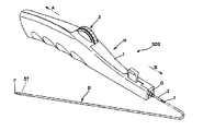
- FIG. 1 is an overall perspective view showing a medical tubular body conveying device according to an embodiment of the present invention
- FIG. Fig. 2 is an enlarged perspective view of a main part showing the configuration of the distal end portion of the delivery catheter according to the embodiment of the present invention
- FIG. 2 is a plan view of the portion where the outer tube, the inner tube, and the protective tube of the medical tubular body conveying device shown in FIG. 1 are present
- 1 is an exploded perspective view of a handle according to an embodiment of the invention
- FIG. FIG. 4 is an enlarged cross-sectional view of a portion where a moving body, a traction member, and a holding portion are present in the handle according to the embodiment of the present invention
- a medical tubular body delivery device SDS (hereinafter also referred to as a stent delivery system) according to an embodiment of the present invention includes a coaxial inner tube 1 and a medical tubular body ST such as a stent.
- a medical tubular body ST (hereinafter also referred to as a stent) held at the distal end of the delivery catheter D, and an operating handle H (hereinafter referred to as a handle (also written as
- proximal side refers to the direction toward the hand side of the user or the operator with respect to the extending direction of the stent delivery system SDS or the longitudinal direction of the delivery catheter D
- distal side refers to the proximal direction. It refers to the side opposite direction, ie, the direction of the subject's side where the stent ST is placed.
- the end on the proximal side is the proximal end
- the vicinity of the proximal end is the proximal end
- the end on the distal side is the distal end
- the vicinity of the distal end is the distal end and
- the stent ST is a self-expanding tubular body made of, for example, a nickel-titanium alloy, which is a superelastic alloy, and has a mesh configuration.
- the stent ST is held at the distal end of the delivery catheter D in a state of being reduced in diameter.
- the distal tip F in the enlarged perspective view of the essential part of FIG. It is formed in a tapered shape depending on the material.
- FIG. 1 shows a delivery catheter D, which is an example of a catheter, and a handle H attached to this delivery catheter D.
- FIG. A system including a handle H and a delivery catheter D attached to the handle H is referred to as a stent delivery system SDS.
- the handle H moves the housing member 2 to the proximal side with respect to the inner tube 1.
- a handle H preferably holds the inner tube 1 .
- the storage member 2 is arranged in the lumen on the distal end side of the medical tubular body ST.
- the stent ST is arranged in the lumen on the distal end side of the housing member 2 .
- the storage member 2 preferably includes an outer tube 15 in which the medical tubular body ST is arranged, and a traction member 13 connected to the outer tube 15 . Further, as shown in FIG. 3, the storage member 2 may be composed of an outer tube 15 that stores the stent ST, and a pulling member 13 fixed to the proximal side of the outer tube 15 . Furthermore, the storage member 2 may comprise a protective tube 14 covering part of the outer tube 15 and the traction member 13 . Protective tube 14 is preferably positioned in the lumen where the proximal end of outer tube 15 and retraction member 13 are located.
- a distal tip F is preferably provided at the distal end of the inner tube 1 .
- the distal tip F has a lumen which preferably communicates with the lumen of the inner tube 1 . Since the distal tip F constitutes the distal end of the delivery catheter D, when the delivery catheter D is inserted into the forceps channel of the endoscope to transport the stent ST to the lesion site, the distal end of the delivery catheter D can be can be prevented from damaging the in vivo lumen. In addition, since the tip F is located at the distal end of the delivery catheter D, the followability of the delivery catheter D to the preceding guide wire and forceps channel and the deliverability of the tip of the delivery catheter D to the lesion are enhanced. and the operability of the stent delivery system SDS is improved.
- FIG. 3(a) is a partial plan view of the stent delivery system SDS shown in FIG. 1, showing a plan view of a state in which the stent ST is housed in the delivery catheter D, similar to FIG. 2(a).
- FIG. 3(b) is a plan view of the stent delivery system SDS shown in FIG. 1 in which the outer tube 15 is moved proximally and the stent ST is exposed from the stent delivery system SDS and radially expanded. show.
- the outer tube 15 is located at the distal part of the storage member 2, and the stent ST is arranged in the lumen of the outer tube 15.
- the outer tube 15 is formed to be movable in the far-near direction with respect to the inner tube 1 and the protective tube 14, and FIG. (b) shows a state in which the outer tube 15 is located on the most proximal side.
- the outer tube 15 protects the stent ST from being exposed outside the storage member 2 as shown in FIG. 3(a) when the stent ST is transported to the lesion site.
- the outer tube 15 functions to hold the stent ST in a reduced diameter state during delivery of the stent ST, thereby facilitating delivery of the stent ST to the lesion site.
- the length of the outer tube 15 in the far-near direction can be appropriately set according to the length in the far-near direction of the stent ST placed in the lumen, and can be, for example, about 50 mm to 800 mm.
- the range in which the outer tube 15 can move in the far-near direction can be appropriately set according to the length of the stent ST placed in the lumen of the outer tube 15 in the far-near direction. Long is preferred.
- the outer diameter of the outer tube 15 may be, for example, approximately 0.5 mm to 3.5 mm.
- the perspective direction can be rephrased as the longitudinal axis direction or the longitudinal direction.
- a typical example of the medical tubular body ST is a stent.
- a stent By using a stent, it is possible to treat various diseases caused by narrowing or obstruction of a living body lumen such as a digestive tract such as a bile duct or a blood vessel.
- the medical tubular body ST includes a single linear metal or coil-shaped body made of a polymer material, a metal tube or a tube made of a polymer material cut out with a laser or the like, or a linear member. There are those assembled by welding, and those formed by weaving multiple linear metals.
- a stent graft, an obturator, an injection catheter, a prosthetic valve, etc. can be used in addition to a stent.
- the medical tubular body ST is (i) mounted (mounted) on the surface of a balloon, transported to the lesion site, and expanded by the balloon at the lesion site. and (ii) the self-expanding type, in which the medical tubular body is transported to the lesion while the expansion is suppressed, and the medical tubular body expands by itself by removing the member that suppresses the expansion at the lesion. can be classified.
- the stent delivery system SDS is preferably used for carrying a self-expanding medical tubular body, and the outer tube 15 functions as a member that suppresses expansion of the stent ST.
- the stent ST contracts in the radial direction and expands in the longitudinal direction, so that the stent ST assumes a diameter-reduced state that is a more elongated cylindrical shape than in the expanded state.
- the diameter of the self-expanding medical tubular body can be made smaller than the balloon-expandable medical tubular body.
- the inner tube 1 is arranged in the lumen of the medical tubular body ST. That is, the inner tube 1 is arranged in the lumen of the storage member 2 and the lumen of the stent ST.
- the inner tube 1 is arranged in the lumen of the outer tube 15 and the lumen of the stent ST, and extends proximally from the proximal end of the outer tube 15 .
- the stent ST is delivered into the body by the stent delivery system SDS, the stent ST is arranged between the inner tube 1 and the outer tube 15 in the radial direction.
- a guide wire is passed through the lumen of the inner tube 1 .
- the length of the inner tube 1 in the far-near direction may be, for example, about 800 mm to 3000 mm.
- the outer diameter of the inner tube 1 may be, for example, approximately 0.3 mm to 3.0 mm.
- the proximal end of the distal tip F is preferably positioned closer to the proximal side than the distal end of the outer tube 15 when the outer tube 15 is positioned on the most distal side. That is, the proximal end of distal tip F is preferably in the lumen of the distal end of outer tube 15 . Since the proximal end of the distal tip F is in the lumen of the distal end of the outer tube 15, when the delivery catheter D is inserted into the forceps channel of the endoscope to convey the stent ST to the lesion site, The outer tube 15 can easily follow the bending motion of the distal tip F, and the operability of the delivery catheter D can be improved when the stent ST is transported to the lesion site.
- a protective tube 14 in which the proximal end of the outer tube 15 is arranged in the lumen.
- the proximal end of the outer tube 15 and the inner tube 1 are arranged in the lumen of the protective tube 14 , and the protective tube 14 extends proximally from the proximal end of the outer tube 15 .
- a handle H is provided on the proximal side of the protective tube 14 for the user to operate the stent delivery system SDS.
- the length of the protection tube 14 in the distance direction may be, for example, about 500 mm to 2200 mm.
- the outer diameter of the protective tube 14 may be, for example, approximately 0.5 mm to 3.5 mm.
- the proximal end of the outer tube 15 is preferably placed in the lumen of the protective tube 14 with the outer tube 15 positioned most proximally and most distally.
- the length of the proximal end portion of the outer tube 15 disposed in the lumen of the protective tube 14 in the far-near direction may be, for example, 1 mm or more and 50 mm or less when the outer tube 15 is located at the most distal side.
- At least part of the portion of the inner tube 1 extending proximally from the proximal end of the outer tube 15 is disposed in the lumen of the protective tube 14, and the portion further distal than that, specifically The portion overlapping the proximal end of the outer tube 15 that is placed in the lumen of the protective tube 14 is also placed in the lumen of the protective tube 14 .
- the protective tube 14 is preferably provided with a guidewire port 12 for passing a guidewire through the lumen of the inner tube 1 . That is, the protective tube 14 preferably has a guidewire port 12 through which a guidewire is inserted through the lumen and communicates with the inner tube 1 .
- the guidewire port 12 is provided as an opening for passing a guidewire inside the delivery catheter D. As shown in FIG.
- the guidewire normally enters the distal end (tip F) of the inner tube 1 and exits the guidewire port 12 to the lumen of the inner tube 1. is inserted into the In this case, the guidewire port 12 serves as an opening for leading the guidewire from the lumen of the inner tube 1 to the outside of the stent delivery system SDS.
- the position of the guidewire port 12 in the far-near direction may be appropriately set according to the type of stent delivery system SDS, ie, rapid exchange type or over-the-wire type.
- FIG. 3 shows a configuration example of a rapid exchange type medical tubular body delivery device in which a guide wire is inserted halfway from the distal end to the proximal end of the shaft portion. It can also be applied to an over-the-wire type medical tubular body delivery device in which a guide wire is inserted from the distal end to the proximal end of the shaft portion.
- Guidewire port 12 is preferably proximal to the proximal end of outer tube 15, with outer tube 15 being most proximal.
- a traction member 13 is preferably connected to the proximal end of the outer tube 15 .
- a retraction member 13 extends proximally from the proximal end of outer tube 15, is disposed within the lumen of protective tube 14, and is connected to handle H, either directly or via another member.
- the handle H By manipulating the handle H, the traction member 13 and the outer tube 15 can be moved in the far-near direction. For example, by pulling the pulling member 13 proximally from the state shown in FIG. ), the stent ST can be exposed outside the delivery catheter D and left in the body.
- the traction member 13 is sent distally, the outer tube 15 is moved distally with respect to the inner tube 1 and the protective tube 14, and the stent ST is pulled outward again. It is also possible to house the stent ST in the lumen of the tube 15 and adjust the indwelling position of the stent ST. It should be noted that the inner tube 1 and the protective tube 14 do not move proximally by pulling the pulling member 13 proximally.
- traction member 13 may be connected to the inner surface of outer tube 15 or may be connected to the outer surface of outer tube 15 . may be connected to the peripheral wall between the Alternatively, the proximal end portion of the outer tube 15 may be of a multi-layer structure, the distal end portion of the pull member 13 may be arranged between the layers, and the pull member 13 may be connected to the outer tube 15 .
- known joining means such as adhesion with an adhesive, welding, fitting, and interlayer pressure bonding of the outer tube 15 having a multi-layer structure can be employed.
- Only one traction member 13 may be provided, or a plurality thereof may be provided. When a plurality of traction members 13 are provided, it is preferable that the plurality of traction members 13 be provided at different positions in the circumferential direction of the outer tube 15 . In order to make the outer diameter of the protective tube 14 smaller, it is preferable that only one pulling member 13 is provided.
- the delivery catheter D is configured as described above, so that the outer tube 15 is pulled proximally with respect to the inner tube 1 and the protective tube 14, and the stent ST is placed in the body lumen. It becomes easy to indwell at a desired position with high accuracy. Specifically, when the outer tube 15 is moved proximally, the outer tube 15 can be housed in the lumen of the protective tube 14, so when the outer tube 15 is moved in the far-near direction, the outer tube 15 can be It is possible to reduce frictional resistance caused by the tube 15 coming into contact with the forceps channel and the forceps port of the endoscope.
- the operating load when moving the outer tube 15 in the far-near direction is reduced, and the stent ST can be stably deployed.
- the entire delivery catheter D can be moved to the proximal side. can be suppressed, and the stent ST can be placed at a desired position with high accuracy.
- the space between the outer tube 15 and the inner tube 1 and the space between the protective tube 14 and the inner tube 1 are separated. It is desirable to evacuate the air present in the intervening space and replace it with water or saline.
- the outer tube 15 and the inner tube 1 can be separated when moving the outer tube 15 in the near and far directions.
- the frictional resistance between the outer tube 15 and the protective tube 14 By reducing the frictional resistance between the outer tube 15 and the protective tube 14 , the operating load of the outer tube 15 can be further reduced.
- the air inside the delivery catheter D is removed so that the air is mixed in the blood vessel when the outer tube 15 is moved in the far-near direction. You can also prevent it from doing so.
- a fluid such as ethylene oxide gas
- the sterilization medium can easily permeate into the delivery catheter D and be discharged. As a result, sterilization efficiency is improved, and safety and production efficiency can also be improved.
- Fig. 4 shows a perspective view of the handle H according to the embodiment of the present invention, which is disassembled in the longitudinal direction.
- the handle H includes a base I that houses the storage member 2 and a movable body 5 that can move in the longitudinal direction of the storage member 2 .
- the moving body 5 may be composed of a slide mechanism for moving the storage member 2 in the longitudinal direction with respect to the inner tube 1 .
- the slide mechanism preferably includes a slide body 5 that can move in the longitudinal direction of the storage member 2, and a drive section 6 for moving the slide body. When the storage member 2 is held by the slide body, the slide body can be moved in the longitudinal direction by the drive unit 6 to move the storage member 2 relative to the inner tube 1 .
- the drive unit 6 is not particularly limited as long as it can move the moving body 5 (slide body) in the longitudinal direction.
- FIG. 4 shows a drive unit 6 using a rack-and-pinion mechanism and a thumbwheel 3 .
- a slide body is provided with a thumbwheel 3 having a gear portion 3A, a rotating body 4 (pinion) having teeth meshing with the gear portion 3A, and rack teeth 5A meshing with the teeth 4A of the rotating body 4.
- the moving body 5 (slide body) is provided with a handle (not shown), and the base body I is provided with an opening rail (not shown), so that the operator can grasp the handle. and pull proximally to retract the slide.
- the moving body 5 has an insertion passage 8A through which the storage member 2 is rotatably inserted.
- the insertion path 8A may have any configuration as long as it can rotatably insert the storage member 2, and examples thereof include holes and grooves. Since the moving body 5 has the insertion path 8A through which the storage member 2 is rotatably inserted, the storage member 2 can rotate relative to the moving body 5 and the handle H within the insertion path 8A. Therefore, even if the medical tubular body transporting device SDS is twisted in the process of transporting the medical tubular body ST by the medical tubular body transporting device SDS, the operator must turn the handle H in order to untwist it. disappears. As a result, the operator does not need to turn the handle H, which is unrelated to treatment.
- the storage member 2 has a forward prevention portion 9 arranged on the storage member 2 , and at least a part of the forward prevention portion 9 is in contact with the moving body 5 .
- the movable body 5 comes into contact with at least a portion of the advance prevention section 9 .
- the storage member 2 can be moved to the proximal side by the moving body 5 coming into contact with at least a part of the forward preventing portion 9 . Since the storage member 2 is rotatably inserted into the moving body 5 through the insertion passage 8A, the storage member 2 may move distally. can prevent the storage member 2 from moving to the distal side.
- FIG. 5 is a schematic cross-sectional view enlarging the periphery of the holding portion 8 in FIG.
- a holding portion 8 is provided on a moving body 5 (sliding body).
- the holding portion 8 has an insertion passage 8A, and the storage member 2 is inserted through the insertion passage 8A.
- the insertion passage 8A is a hole through which the storage member 2 can be inserted. That is, the moving body 5 has a holding portion 8 provided with an insertion hole through which the storage member 2 can be rotatably inserted.
- the shape of the insertion hole is not limited, and may be circular or U-shaped.
- the storage member 2 Since the storage member 2 is not fixed to the holding portion 8, it is rotatable with respect to the slide member and the handle H within the insertion hole 8A. Accordingly, even if the medical tubular body transporting device SDS is twisted in the process of transporting the medical tubular body ST by the medical tubular body transporting device SDS, the operator turns the handle H in order to untwist it. no longer needed. Therefore, there is an effect that the operator does not need to turn the handle H, which is unrelated to treatment.
- the storage member 2 is provided with an advance preventing portion 9 on the proximal side of the insertion passage 8 ⁇ /b>A (insertion hole), and the holding portion 8 pushes the storage member 2 through the advance preventing portion 9 . Hold.
- the moving body 5 silica body
- the slide body comes into contact with the forward prevention part 9 held by the storage member 2, thereby causing the storage member 2 to move.
- the storage member 2 is rotatable with respect to the slide body and the handle H within the insertion passage 8A.
- the tubular body conveying device SDS for medical use is twisted, the operator does not need to turn the handle H to untwist it, and the stent ST can be placed.
- the storage member 2 since the storage member 2 is not fixed to the holding portion 8 within the insertion passage 8A, the storage member 2 may move distally. Abutting the end prevents the storage member 2 from moving distally. As a result, the tip of the storage member 2 can be prevented from colliding with the tip F. As shown in FIG.
- the storage member 2 is composed of the outer tube 15 and the traction member 13 connected to the outer tube 15, it is preferable to use a highly rigid metal wire as the traction member 13, for example.
- a metal wire for the pulling member 13
- the rigidity of the delivery catheter D can be increased, and the pushability of the medical tubular body delivery device SDS can be improved.
- the pulling member 13 is made of a metal wire
- the pulling member 13 itself can be thinner than when the pulling member 13 has a tubular shape, so the outer diameter of the delivery catheter D can be made thinner. As a result, the followability of the delivery catheter D to the blood vessel can be improved.
- stainless steel (SUS) or the like is preferable as the metal material forming the metal wire.
- the forward preventing portion 9 is fixed to the storage member 2, and its material and shape are not particularly limited as long as it has an outer diameter larger than the inner diameter of the minimum portion of the insertion passage 8A.
- the method of fixing the forward preventing portion 9 to the storage member 2 is not particularly limited, and may be fixed by welding, bonding, winding an elongated member in a coil shape, or fixing by crimping a tubular member.
- the advance preventing portion 9 may be formed from the storage member 2, or a part of the storage member 2 may be processed so as to have an outer diameter larger than the outer diameter of the insertion passage 8A. For example, part of the storage member 2 or the shape of the proximal end may be processed.
- the storage member 2 may be processed into a state in which the outer diameter is expanded (provided with a flare, taper, or thick portion) by heat, a bent state, a coiled state, or the like.
- a method of forming the advance preventing portion 9 a method of bonding a resin pipe or a method of crimping a stainless steel pipe is more preferable in that the manufacturing method is easy.
- the distal end of the advance prevention part 9 is in contact with the proximal end of the moving body 5 .
- the ends of the forward preventing portion 9 and the moving body 5 come into contact with each other, and the storage member 2 to which the forward preventing portion 9 is fixed is removed. Distal migration becomes less likely.
- the distal end of the forward movement preventing portion 9 can be located on the distal side of the proximal end of the moving body 5 .
- the fact that the distal end of the advancement preventing portion 9 can be located on the distal side of the proximal end of the moving body 5 means that, for example, the distal end of the advancement preventing portion 9 is located at the proximal end of the moving body 5 . It has a hole larger than the outer shape of the end, and the distal end of the advancement prevention part 9 is inserted into this hole. It has a hole larger in size than the outer shape of the body, and the proximal end of the moving body 5 is inserted into this hole.
- the distal end of the advancement preventing portion 9 can be positioned further distally than the proximal end of the moving body 5 , the distal end portion of the advancement preventing portion 9 and the proximal end portion of the moving body 5 are separated from each other. It can fit and make it harder for the storage member 2 to move distally.
- the distal end of the advancement preventing portion 9 is located on the distal side of the proximal end of the insertion passage 8A, and the proximal end of the advancement prevention portion 9 is located on the proximal side of the distal end of the insertion passage 8A. is preferred. Since the distal end of the advancement preventing portion 9 is located on the distal side of the proximal end of the insertion passage 8A, and the proximal end of the advancement preventing portion 9 is located on the proximal side of the distal end of the insertion passage 8A, Movement of the storage member 2 in the longitudinal direction can be prevented by the moving body 5 having the insertion passage 8A.
- the moving body 5 has a holding portion 8, and the insertion passage 8A is formed in the holding portion 8. Since the moving body 5 has the holding portion 8 in which the insertion passage 8A is formed, the forward preventing portion 9 and the holding portion 8 of the moving body 5 come into contact with each other, so that the contact area of the forward preventing portion 9 increases and the storage space is reduced. The effect of preventing movement of the member 2 can be enhanced.
- the advance prevention portion 9 is preferably arranged in contact with the holding portion 8 .
- the forward preventing portion 9 can be prevented from moving by the holding portion 8 .
- the distal end of the advance prevention part 9 is in contact with the proximal end of the holding part 8 .
- the ends of the forward preventing portion 9 and the holding portion 8 are brought into contact with each other. 2 can be more prevented from moving distally.
- the distal end of the advance prevention part 9 can be positioned further distally than the proximal end of the holding part 8 . That is, it is preferable that the advance prevention part 9 can move beyond the proximal end of the holding part 8 to the distal side. Since the distal end of the advancement preventing portion 9 can be located on the distal side of the proximal end of the holding portion 8, the distal end portion of the advancement preventing portion 9 and the insertion passage formed in the holding portion 8 are separated. 8A are in contact with each other, and the contact area can be increased. Therefore, the effect of preventing the storage member 2 from moving can be enhanced by the friction generated between the distal end portion of the advance prevention portion 9 and the insertion passage 8A of the holding portion 8 .
- the forward prevention part 9 may be arranged so as to contact the proximal end of the insertion passage 8A.
- the advance preventing portion 9 is not fixed to the holding portion 8 and is configured to freely rotate inside the insertion passage 8A.
- the stent ST can be placed quickly. Further, it is possible to prevent the advance preventing portion 9 provided on the storage member 2 or the pulling member 13 from moving near the proximal end of the holding portion 8 and colliding with other members inside the handle H.
- the insertion passage 8A When the insertion passage 8A is a hole, the insertion passage 8A has a variable inner diameter as shown in FIG.
- the forward preventing portion 9 may be in contact with the enlarged region, and the forward preventing portion 9 may enter the region where the inner diameter is enlarged.
- the advance preventing portion 9 is not fixed to the holding portion 8 and is configured to freely rotate inside the insertion passage 8A. With such a configuration, when the storage member 2 or the pulling member 13 is pulled proximally to place the stent ST in the body, the stent ST can be placed quickly.
- a retreat prevention part 10 may be provided on the distal side of the insertion passage 8A.
- the storage member 2 is rotatable within the insertion passage 8A and is not fixed to the holding portion 8 or the moving body 5 (slide body). Therefore, an erroneous operation may move the storage member 2 proximally and unintentionally start deploying the stent ST.
- the storage member 2 has a retraction prevention portion 10 disposed so as to be able to abut against the holding portion 8 on the distal side of the insertion passage 8A, for example, the storage member 2 may be erroneously pulled toward the proximal side before surgery.
- the retraction prevention part 10 abuts against the distal end of the holding part 8, thereby preventing the stent ST from unintentionally deploying. can.
- the storage member 2 is composed of the outer tube 15 and the traction member 13 connected to the outer tube 15, the pushability of the medical tubular body transport device SDS can be improved, and the delivery catheter D can be This is preferable in that the diameter can be reduced and the size of the anti-backup portion 10 can be reduced.
- the backward preventing portion 10 is fixed to the pulling member 13, and its material and shape are not particularly limited as long as it has an outer diameter larger than the inner diameter of the insertion passage 8A. It may be made of resin or metal. may The fixing method is also not particularly limited, and may be fixed by welding, bonding, winding an elongated member in a coil shape, or fixing by crimping a tubular member. Alternatively, the retraction preventing portion 10 may be formed from the storage member 2, or may be processed so that a portion of the storage member 2 has an outer diameter larger than the outer diameter of the insertion passage 8A. For example, the shape of part of the storage member 2 may be processed.
- the storage member 2 may be processed into a state in which the outer diameter is expanded (provided with a flare, taper, or thick portion) by heat, a bent state, a coiled state, or the like.
- a method for forming the retreat preventing portion 10 a method of bonding a resin pipe or a method of crimping a stainless steel pipe is more preferable in that the manufacturing method is easy.
- the storage member 2 has a retreat prevention section 10 on the distal side of the advance prevention section 9 , and at least a part of the retreat prevention section 10 preferably contacts the moving body 5 . Since the storage member 2 has the retraction prevention portion 10 which is located on the distal side of the advance prevention portion 9 and is at least partially in contact with the moving body 5, the storage member 2 may be accidentally operated by the user of the stent delivery system SDS. 2 is to be moved proximally, the retraction prevention part 10 prevents the storage member 2 from moving proximally, thereby preventing unintended deployment of the stent ST.
- the proximal end of the anti-retreat part 10 is preferably in contact with the distal end of the moving body 5. Since the proximal end of the anti-retreat part 10 contacts the distal end of the movable body 5 , the ends of the anti-retraction part 10 and the movable body 5 are brought into contact with each other. Increases the effect of preventing movement to the side.
- the proximal end of the anti-retreat part 10 can be located closer to the proximal side than the distal end of the moving body 5 . Since the proximal end of the anti-retreat part 10 can be positioned closer to the proximal side than the distal end of the movable body 5, the proximal end of the anti-retraction part 10 and the distal end of the movable body 5 are fitted. This state makes it difficult for the storage member 2 to move to the proximal side.
- the distal end of the anti-retraction part 10 is on the distal side of the proximal end of the insertion passage 8A, and the proximal end of the anti-retraction part 10 is on the proximal side of the distal end of the insertion passage 8A. is preferred. Since the distal end of the anti-retraction part 10 is on the distal side of the proximal end of the insertion passage 8A, and the proximal end of the anti-retraction part 10 is on the proximal side of the distal end of the insertion passage 8A, The moving body 5 having the insertion path 8A can enhance the effect of preventing the storage member 2 from moving in the longitudinal direction.
- the anti-retreat part 10 is preferably arranged in contact with the holding part 8 .
- the movement of the anti-backup portion 10 can be prevented by the holding portion 8 .
- the movement of the storage member 2 can be further prevented.
- the proximal end of the anti-backup part 10 is preferably in contact with the distal end of the holding part 8.
- the ends of the anti-backup portion 10 and the holding portion 8 come into contact with each other, increasing the area of contact with each other. can enhance the effect of preventing proximal migration of the .
- the proximal end of the anti-retraction part 10 can be positioned closer to the proximal side than the distal end of the holding part 8 .
- the anti-backup part 10 can move beyond the distal end of the movable body 5 to the proximal side. Since the proximal end of the anti-retreat part 10 can be positioned closer to the proximal side than the distal end of the holding part 8, the proximal end part of the anti-retreat part 10 and the insertion passage of the moving body 5 are separated. 8A contact with each other, and the contact area between the anti-retreat part 10 and the moving body 5 can be increased. As a result, the friction generated between the proximal end portion of the anti-retreat portion 10 and the insertion passage 8A enhances the effect of preventing the movement of the storage member 2 .
- the housing member 2 is composed of an outer tube 15 and a pulling member 13 connected to the outer tube 15, and the protective tube 14 is provided with the proximal end side of the outer tube 15 and the outer tube 15.
- the proximal end side of the inner tube 1 and the pulling member 13 are arranged in the lumen and the guide wire port 12 is provided, the pulling member 13 on the proximal side of the insertion passage 8A is prevented from moving forward.
- a portion 9 may be provided, and a retraction prevention portion 10 may be provided on the traction member 13 on the distal side of the insertion passage 8A.
- a guide wire port 12 is provided for inserting a guide wire necessary for transporting the medical tubular body ST into the body.
- both the advance prevention part 9 and the retreat prevention part 10 are provided on the traction member 13, the storage member 2 and the distal tip F may collide with each other while the storage member 2 is rotatable, and the stent ST may be unintentionally damaged. It is more effective because it accomplishes both of preventing deployment.
- the stent delivery system SDS has a protective member 11 arranged on the traction member 13, and the protective member 11 preferably abuts against the retraction prevention portion 10.
- the protection member 11 abutting on the retraction prevention part 10 is arranged on the traction member 13 to prevent the storage member 2 from being bent in the handle H and retracting, thereby unintentionally deploying the stent ST. can be prevented.
- a protective member 11 is disposed on the distal side of the distal end of the holding portion 8 provided on the moving body 5 (slide body) so as to cover the storage member 2. good too.
- the protective member 11 is in contact with the distal end side of the anti-retreat portion 10 .
- the material and shape of the protective member 11 are not limited as long as they can cover the storage member 2, resin materials such as polyamide, polyamide elastomer, and polyethylene are preferable.
- the protective member 11 may be attached to the handle H or may be attached to the protective tube 14 .
- the protection member 11 may also serve as the anti-retreat part 10 without providing the anti-retreat part 10 .
- the protective member 11 is preferably fixed to the base I. Since the protective member 11 is fixed to the base I, the protective member 11 arranged so as to cover the storage member 2 is bent when receiving a force in the direction in which the storage member 2 is bent inside the handle H. It is possible to prevent the storage member 2 from being put away, and to effectively prevent the bending of the storage member 2. - ⁇
- the protective member 11 is preferably fixed to the protective tube 14. By fixing the protection member 11 to the protection tube 14, the storage member 2 can be supported by the protection member 11 from the outside of the storage member 2, and the effect of preventing the deflection of the storage member 2 can be enhanced.
- the protective tube 14 is preferably fixed to the base I and rotatable with respect to the handle H. Since the protective tube 14 is fixed to the base I and is rotatable with respect to the handle H, the protective tube 14 is less likely to bend, and the bending of the protective tube 14 can prevent the storage member 2 from bending. can. Further, since the protective tube 14 is rotatable with respect to the handle H, when the protective tube 14 is twisted, the twist can be eliminated by rotating the handle H.
- the inner tube 1 is preferably fixed to the base I and rotatable with respect to the handle H. Since the inner tube 1 is fixed to the base I and is rotatable with respect to the handle H, the inner tube 1 is hard to bend, and the bending of the inner tube 1 can prevent the storage member 2 from bending. Further, when the inner tube 1 is twisted, the twist of the delivery catheter D can be restored by rotating the handle H.
- the inner tube 1 preferably has a receiver G attached to its proximal end and is configured to be able to fit into the cavity at the distal end of the handle H. Since the inner tube 1 has the receiver G and is configured to be fitted into the handle H, the inner tube 1 can also be attached to the handle H so as to be rotatable. Furthermore, if protective tube 14 is present, a receiver G, not shown, is attached near the proximal end of protective tube 14 and is configured to fit into a cavity near the distal end of handle H. good too. Since the protection tube 14 has the receiver G and is configured to be fitted into the handle H, the protection tube 14 can be attached to the handle H so as to be rotatable. The inner tube 1 and protective tube 14 may be attached to the handle H individually or together.
- the inner tube 1, the storage member 2 (the outer tube 15 and the traction member 13), and the protective tube 14 can each rotate with respect to the handle H. Therefore, even if the delivery catheter D is twisted when the stent delivery system SDS is delivered to the treatment site, the handle H can be rotated with respect to the delivery catheter D, and the handle H can be operated regardless of the orientation of the delivery catheter D. can.
- the storage member 2 that is movable for placing the medical tubular body ST but also the inner tube 1 and the protective tube 14 that support the placement of the medical tubular body ST are attached to the handle H. Since it is rotatable, there is an effect that the medical tubular body conveying device SDS is much less likely to be twisted. Furthermore, it is possible to reduce the interference between these members, particularly the winding of the traction member 13, and the like.
- Inner tube 2 Storage member 3: Thumbwheel 3A: Gear part 4: Rotating body 4A: Teeth of rotating body 5: Moving body 5A: Teeth of rack 6: Driving part 8: Holding part 8A: Insertion path 9: Advance Prevention part 10: Retraction prevention part 11: Protection member 12: Guide wire port 13: Traction member 14: Protection tube 15: Outer tube A: Proximal side B: Distal side D: Delivery catheter F: Distal tip G: Receiver H: Handle I: Substrate P: Pusher member SDS: Medical tubular body conveying device ST: Medical tubular body conveying device ST: Medical tubular body conveying device ST: Medical tubular body conveying device ST: Medical tubular body conveying device ST: Medical tubular body conveying device ST: Medical tubular body conveying device ST: Medical tubular body conveying device ST: Medical tubular body conveying device ST: Medical tubular body conveying device ST: Medical tubular body conveying device ST: Medical tubular body conveying device ST: Medical tubular body conveying device ST: Medical tubular body
Landscapes
- Health & Medical Sciences (AREA)
- Engineering & Computer Science (AREA)
- Biomedical Technology (AREA)
- Life Sciences & Earth Sciences (AREA)
- General Health & Medical Sciences (AREA)
- Animal Behavior & Ethology (AREA)
- Heart & Thoracic Surgery (AREA)
- Veterinary Medicine (AREA)
- Public Health (AREA)
- Oral & Maxillofacial Surgery (AREA)
- Cardiology (AREA)
- Surgery (AREA)
- Transplantation (AREA)
- Vascular Medicine (AREA)
- Nuclear Medicine, Radiotherapy & Molecular Imaging (AREA)
- Molecular Biology (AREA)
- Medical Informatics (AREA)
- Gastroenterology & Hepatology (AREA)
- Pulmonology (AREA)
- Media Introduction/Drainage Providing Device (AREA)
Priority Applications (1)
| Application Number | Priority Date | Filing Date | Title |
|---|---|---|---|
| JP2023510199A JPWO2022208956A1 (https=) | 2021-03-30 | 2021-10-22 |
Applications Claiming Priority (2)
| Application Number | Priority Date | Filing Date | Title |
|---|---|---|---|
| JP2021-058325 | 2021-03-30 | ||
| JP2021058325 | 2021-03-30 |
Publications (1)
| Publication Number | Publication Date |
|---|---|
| WO2022208956A1 true WO2022208956A1 (ja) | 2022-10-06 |
Family
ID=83458319
Family Applications (1)
| Application Number | Title | Priority Date | Filing Date |
|---|---|---|---|
| PCT/JP2021/039049 Ceased WO2022208956A1 (ja) | 2021-03-30 | 2021-10-22 | 医療用管状体搬送装置 |
Country Status (2)
| Country | Link |
|---|---|
| JP (1) | JPWO2022208956A1 (https=) |
| WO (1) | WO2022208956A1 (https=) |
Citations (2)
| Publication number | Priority date | Publication date | Assignee | Title |
|---|---|---|---|---|
| JP2003334254A (ja) * | 2002-04-23 | 2003-11-25 | Medtronic Ave Inc | 迅速摺動機構を有する統合機械的ハンドル |
| JP2011078843A (ja) * | 2011-01-25 | 2011-04-21 | Terumo Corp | 生体器官拡張器具 |
-
2021
- 2021-10-22 JP JP2023510199A patent/JPWO2022208956A1/ja active Pending
- 2021-10-22 WO PCT/JP2021/039049 patent/WO2022208956A1/ja not_active Ceased
Patent Citations (2)
| Publication number | Priority date | Publication date | Assignee | Title |
|---|---|---|---|---|
| JP2003334254A (ja) * | 2002-04-23 | 2003-11-25 | Medtronic Ave Inc | 迅速摺動機構を有する統合機械的ハンドル |
| JP2011078843A (ja) * | 2011-01-25 | 2011-04-21 | Terumo Corp | 生体器官拡張器具 |
Also Published As
| Publication number | Publication date |
|---|---|
| JPWO2022208956A1 (https=) | 2022-10-06 |
Similar Documents
| Publication | Publication Date | Title |
|---|---|---|
| JP5748163B2 (ja) | 迅速交換機能を備えたステント送出カテーテル | |
| EP3266414B1 (en) | Implant delivery system with interlocked rx port orientation | |
| US5980533A (en) | Stent delivery system | |
| JP5350248B2 (ja) | 分岐部カテーテルアセンブリ | |
| US20090264865A1 (en) | Insertion assisting tool for catheter, catheter assembly, and catheter set | |
| JP2022504291A (ja) | 医療用インプラント送達システム | |
| US20080269721A1 (en) | Interventional medical device system having a spiral section and radiopaque marker and method of making the same | |
| JP4709755B2 (ja) | 分岐ステント搬送システム | |
| EP3811899B1 (en) | Stent for bypass between hollow organs and stent delivery system including stent for bypass between hollow organs | |
| WO2007124161A1 (en) | Guidewire placement device | |
| CN112714659B (zh) | 医疗用管状体运送装置 | |
| WO2022208956A1 (ja) | 医療用管状体搬送装置 | |
| JP2013223664A (ja) | バルーンカテーテル用保護スリーブ、バルーンカテーテルシステムおよびステントデリバリーシステム | |
| JP7378460B2 (ja) | 医療用管状体搬送装置およびその製造方法 | |
| JP7378459B2 (ja) | 医療用管状体搬送装置およびその製造方法 | |
| JP7329043B2 (ja) | 医療用管状体搬送装置 | |
| JP7329042B2 (ja) | 医療用管状体搬送装置 | |
| JP7824929B2 (ja) | 医療用管状体搬送装置の製造方法 | |
| JP7803755B2 (ja) | 医療用管状体内装チューブの製造方法および医療用管状体搬送装置の製造方法 | |
| JP7610704B2 (ja) | デリバリーデバイスおよび内視鏡システム | |
| WO2025074843A1 (ja) | 医療用具 | |
| JP7383625B2 (ja) | カテーテル | |
| CN116322579A (zh) | 医疗用管状体运送装置 | |
| JP2020048922A (ja) | 展開物デリバリーシステム | |
| WO2025150326A1 (ja) | 医療用具 |
Legal Events
| Date | Code | Title | Description |
|---|---|---|---|
| 121 | Ep: the epo has been informed by wipo that ep was designated in this application |
Ref document number: 21935112 Country of ref document: EP Kind code of ref document: A1 |
|
| WWE | Wipo information: entry into national phase |
Ref document number: 2023510199 Country of ref document: JP |
|
| NENP | Non-entry into the national phase |
Ref country code: DE |
|
| 122 | Ep: pct application non-entry in european phase |
Ref document number: 21935112 Country of ref document: EP Kind code of ref document: A1 |