WO2022208798A1 - 残留塩素自動分析計 - Google Patents
残留塩素自動分析計 Download PDFInfo
- Publication number
- WO2022208798A1 WO2022208798A1 PCT/JP2021/013999 JP2021013999W WO2022208798A1 WO 2022208798 A1 WO2022208798 A1 WO 2022208798A1 JP 2021013999 W JP2021013999 W JP 2021013999W WO 2022208798 A1 WO2022208798 A1 WO 2022208798A1
- Authority
- WO
- WIPO (PCT)
- Prior art keywords
- seawater
- residual chlorine
- concentration
- chlorine
- measurement cell
- Prior art date
- Legal status (The legal status is an assumption and is not a legal conclusion. Google has not performed a legal analysis and makes no representation as to the accuracy of the status listed.)
- Ceased
Links
Images
Classifications
-
- G—PHYSICS
- G01—MEASURING; TESTING
- G01N—INVESTIGATING OR ANALYSING MATERIALS BY DETERMINING THEIR CHEMICAL OR PHYSICAL PROPERTIES
- G01N27/00—Investigating or analysing materials by the use of electric, electrochemical, or magnetic means
- G01N27/26—Investigating or analysing materials by the use of electric, electrochemical, or magnetic means by investigating electrochemical variables; by using electrolysis or electrophoresis
-
- G—PHYSICS
- G01—MEASURING; TESTING
- G01N—INVESTIGATING OR ANALYSING MATERIALS BY DETERMINING THEIR CHEMICAL OR PHYSICAL PROPERTIES
- G01N27/00—Investigating or analysing materials by the use of electric, electrochemical, or magnetic means
- G01N27/26—Investigating or analysing materials by the use of electric, electrochemical, or magnetic means by investigating electrochemical variables; by using electrolysis or electrophoresis
- G01N27/416—Systems
Definitions
- the present invention relates to a residual chlorine automatic analyzer.
- Seawater electrolytic chlorine injection is carried out in order to prevent the adhesion of organisms such as barnacles and mussels to the seawater systems of seawater plants such as thermal and nuclear power plants.
- sodium hypochlorite is generated by electrolyzing natural seawater, and an electrolytic solution containing the sodium hypochlorite is injected into a seawater intake to prevent adhesion of marine organisms.
- seawater with zero residual chlorine concentration using the above activated carbon filter it was necessary to switch the system and pass the seawater through the activated carbon filter multiple times using a small pump. For this reason, there is a problem that a very complicated work is required and the device configuration becomes complicated.
- seawater that has repeatedly passed through activated carbon may differ in quality from the local seawater, which may affect the accuracy of calibration.
- Patent Document 2 discloses a technique relating to a method for decomposing hypohalous acid by irradiating a liquid containing hypohalous acid with ultraviolet rays.
- the conditions for light irradiation that can efficiently decompose residual chlorine in seawater have not been studied in the past.
- the present invention has been made in view of the above, and it is an object of the present invention to provide an automatic residual chlorine analyzer that can easily perform zero calibration by efficiently decomposing residual chlorine in seawater.
- the present invention is an automatic residual chlorine analyzer for analyzing residual chlorine in seawater, comprising: a measuring cell for measuring the residual chlorine concentration in the seawater; a light irradiation unit capable of decomposing residual chlorine in the seawater by irradiating the seawater supplied to the cell with light to generate seawater having a residual chlorine concentration of substantially zero;
- the peak wavelength of the light emitted from the light emitting part is within the range of 275 to 285 nm, and relates to an automatic residual chlorine analyzer.
- the residual chlorine automatic analyzer according to (1) which can generate seawater with a residual chlorine concentration of substantially zero.
- a chlorine generation unit is provided upstream of the measurement cell and generates chlorine, the chlorine generation unit generates the chlorine by electrolyzing the seawater on the upstream side of the measurement cell,
- the residual chlorine automatic analyzer according to (1) or (2) which is supplied to the measurement cell.
- the present invention can provide an automatic residual chlorine analyzer that can easily perform zero calibration by efficiently decomposing residual chlorine in seawater.
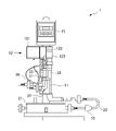
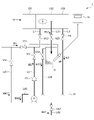
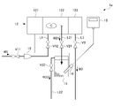
- BRIEF DESCRIPTION OF THE DRAWINGS It is an external view of the residual chlorine automatic analyzer based on 1st Embodiment of this invention. BRIEF DESCRIPTION OF THE DRAWINGS It is the schematic of the functional block of the residual chlorine automatic analyzer which concerns on 1st Embodiment of this invention, and the flow path of seawater. It is a schematic diagram of the functional block of the residual chlorine automatic analyzer and the flow path of seawater according to the second embodiment of the present invention.
- the residual chlorine automatic analyzer according to the present embodiment is an apparatus for analyzing residual chlorine in seawater, and is used, for example, for analyzing residual chlorine in seawater systems of seawater plants such as thermal and nuclear power plants.
- the location of the automatic residual chlorine analyzer is not particularly limited, it can be installed, for example, at the outlet of the thermal or nuclear power plant or at the inlet of the condenser.
- the concentration of residual chlorine at the outlet is usually about 0.02-0.03 mg/L, and the concentration of residual chlorine at the inlet of the condenser is about 0.03-0.05 mg/L.
- the residual chlorine automatic analyzer according to the present embodiment is used for analysis of relatively low-concentration residual chlorine of 0.1 mg/L or less as described above.
- the residual chlorine automatic analyzer 1 includes a light irradiation unit 10, a measurement cell 11, a sampling tank 12, a monitor 15, a sensor 16, a circulation tank 21, a hose 22, and a first pipe 31. , a second pipe 32 and a third pipe 33 . These are fixed to the struts 30 .
- the residual chlorine automatic analyzer 1 is fixed to a post 30 in the order of the circulation tank 21, the light irradiation unit 10, the measurement cell 11, the sampling tank 12, and the monitor 15 from below.
- a first pipe 31 is connected to the sampling tank 12 .
- a light irradiation unit 10 is provided in the middle of the hose 22 .
- a second pipe 32 is connected from the sampling tank 12 to the measurement cell 11 , and a third pipe 33 is connected from the sampling tank 12 to the circulation tank 21 .
- the first pipe 31, the second pipe 32, and the third pipe 33 are fixed to the column 30 in parallel.
- the seawater taken in by the water intake pump from the water outlet of the power plant is sent through the first pipe 31 to the test water tank 122 of the sampling tank 12 .
- the seawater sent to the test water tank 122 flows into the measurement cell 11 through the second pipe 32 .
- surplus seawater is discharged to the circulation tank 21 via the surplus water tank 123 .
- the seawater discharged to the circulation tank 21 can be made to flow into the light irradiation section 10 again, and the seawater can be circulated so as to flow through the light irradiation section 10 a plurality of times. Thereby, even if the light intensity of the light irradiation unit 10 is not sufficient, it is possible to create seawater with a residual chlorine concentration of substantially zero.
- the light irradiation unit 10 has therein a channel through which seawater can flow, including, for example, a water supply port and a water discharge port.
- the light irradiation unit 10 can irradiate the seawater flowing through the internal channel with light having a peak wavelength within the range of 275 to 285 nm.
- the light having the peak wavelength is, for example, LED light.
- the peak wavelength is preferably 277 nm to 283 nm.
- residual chlorine in seawater includes hypochlorite ions, hypobromite ions, free hypochlorous acid, free hypobromous acid and salts thereof, combined residual chlorine, and combined residual bromine.
- the bromine compound is a component that reacts with chlorine in seawater and can be measured as residual chlorine by an automatic residual chlorine analyzer.
- the light irradiation unit 10 can irradiate seawater with light to decompose residual chlorine in the seawater. As a result, it is possible to easily prepare seawater with a substantially zero residual chlorine concentration, which is used for zero calibration of the residual chlorine automatic analyzer 1 .
- the seawater having a substantially zero residual chlorine concentration generated by the light irradiation unit 10 means seawater having a sufficiently lower residual chlorine concentration than the normal measurement range.
- the concentration of residual chlorine at the condenser inlet is usually about 0.03-0.05 mg/L
- the concentration of residual chlorine at the outlet is usually about 0.02-0.03 mg/L.
- seawater with a residual chlorine concentration of 0.03 mg / L or less at the condenser inlet and 0.02 mg / L or less at the water outlet is prepared as seawater with a residual chlorine concentration of substantially zero, and manually analyzed.
- the value can be used for the zero calibration.
- the light irradiation from the light irradiation unit 10 is performed when performing the zero calibration, and the light irradiation from the light irradiation unit 10 is not performed during normal measurement of the residual chlorine automatic analyzer 1 .
- the residual chlorine automatic analyzer 1 detects residual chlorine in a considerably low concentration range of 0.1 mg/L or less. For this reason, the influence of the shift of the zero point due to the adhesion of biofilms to the electrodes or the like is large. Therefore, there is an advantage that the measurement accuracy can be ensured by performing zero calibration of the residual chlorine automatic analyzer 1 at high frequency.
- the installation location of the light irradiation unit 10 is not limited to the above, and may be provided at any location on the upstream side of the measurement cell 11. It is good if there is.
- the upstream side of the measurement cell 11 means all channels through which seawater flowing into the measurement cell 11 flows.
- the circulation path is also included on the upstream side of the measurement cell 11 .
- the light irradiation section 10 may be provided between the test water tank 122 described later and the measurement cell 11 . Further, a plurality of light irradiation units 10 may be provided.
- the test water tank 122 is equipped with an electrolytic cell (not shown) as a chlorine generator, and the electrolytic cell electrolyzes seawater to generate sodium hypochlorite as residual chlorine.
- an electrolytic cell (not shown) as a chlorine generator, and the electrolytic cell electrolyzes seawater to generate sodium hypochlorite as residual chlorine.
- seawater with a higher residual chlorine concentration than the normal measurement range of the residual chlorine automatic analyzer 1 can be created.
- Span calibration can be easily performed using seawater having a relatively high residual chlorine concentration.
- the concentration of residual chlorine generated is not particularly limited, it is preferably 0.1 mg/L or more, for example. More preferably, the residual chlorine concentration is 0.1 mg/L or more and 0.5 mg/L or less.
- the light irradiation section 10 is preferably provided on the upstream side of the electrolytic cell (not shown) as the chlorine generation section.
- seawater having a residual chlorine concentration of substantially zero is created by light irradiation from the light irradiation unit 10, and then the seawater is electrolyzed by the electrolytic cell to produce sodium hypochlorite as chlorine. can be generated. Therefore, the theoretical value of the residual chlorine concentration can be obtained based on the current value of the electrolytic cell, etc., without obtaining the residual chlorine concentration by manual analysis during span calibration. Since span calibration can be performed based on the above theoretical values, span calibration can be performed automatically without manual analysis.
- the seawater containing sodium hypochlorite generated by the electrolysis cell may be used for the purpose of removing obstacles of biological origin adhering to the measurement cell 11 .
- the frequency of electrolysis by the electrolytic cell may be, for example, once every three hours for about 10 minutes.
- the current value of the electrolytic cell is adjusted so that the residual chlorine concentration measured by manual analysis in the circulation tank 21 is 1.0 mg/L.
- Seawater containing sodium hypochlorite generated by electrolysis in the electrolytic cell flows through the second pipe 32 into the measurement cell 11 .
- adherent organisms such as barnacles and mussels, which are biological obstacles in the measurement cell 11, and biofilms are washed away. occurrence is suppressed.
- the electrolytic solution tank 121 stores the electrolytic solution (measurement electrode internal solution).
- a component of the electrolytic solution includes, for example, potassium chloride.
- the residual chlorine concentration in seawater is measured by the sensor 16 and the measured value is displayed on the monitor 15 .
- the seawater flows into the measurement cell 11 through the second pipe 32 without being electrolyzed by the electrolytic cell.
- FIG. 2 is a schematic diagram showing the flow path of seawater in the residual chlorine automatic analyzer 1. As shown in FIG. 2, the same symbols are used for the same components as those shown in FIG. 1, and the detailed description of their functions is omitted.
- an inflow water line L1 a first outflow water line L21, a second outflow water line L22, and an excess water line L3 are provided as lines through which seawater flows between the sampling tank 12 and the circulation tank 21.
- a line L5 is provided as a line through which seawater circulates from the circulation tank 21 to the sampling tank 12 .
- the light irradiation unit 10 is provided in the middle of the channel of the line L5.
- the inflow water line L1 is a line through which seawater as the inflow water W1 flowing into the test tank 122 flows.
- the influent water line L1 includes a valve V11 and a valve V12.
- the inflow water line L1 branches off from the line L41 on the upstream side of the valve V11, and branches off from the line L5 on the downstream side of the valve V11 and on the upstream side of the valve V12.
- the test water tank 122 is provided with an electrolytic cell C as a chlorine generator.
- the influent water line L1 corresponds to the first pipe 31 in FIG.
- the outflow water line is composed of a first outflow water line L21 and a second outflow water line L22.
- the first outflow water line L21 corresponds to the second pipe 32 in FIG.
- the first outflow water line L21 is a line through which seawater as the first outflow water W21 flowing out from the test water tank 122 to the measurement cell 11 flows.
- the first outflow water line L21 includes a valve V21.
- the valve V ⁇ b>21 is a valve that adjusts the flow rate of the first outflow water W ⁇ b>21 flowing out of the test water tank 122 to the measurement cell 11 .
- the second outflow water line L22 is a line for causing the second outflow water W22 flowing out from the measurement cell 11 to flow out to the circulation tank 21.
- the second outflow water line L22 has a valve V22.
- the surplus water line L3 is a line through which surplus water W3 flowing out from the surplus water tank 123 to the circulation tank 21 flows.
- the surplus water line L3 has a third valve V3.
- the third valve V3 is a valve that adjusts the flow rate of surplus water W3 flowing out of the surplus water tank 123 to the circulation tank 21 .
- the surplus water line L3 corresponds to the third pipe 33 in FIG.
- Lines L41, L42, and L43 are lines for discharging seawater to the outside of the residual chlorine automatic analyzer 1.
- Line L41 is a line for discharging seawater W41 from the outside to the outside without flowing into the residual chlorine automatic analyzer 1 when seawater is circulated inside the residual chlorine automatic analyzer 1 during zero calibration. be.
- the line L41 has a valve V41.
- a line L42 is a line for discharging seawater W42 having a high residual chlorine concentration generated during span calibration from the circulation tank 21 to the outside.
- Line L42 is provided with valve V42.
- a line L43 is a line through which excess seawater W43 flowing into the circulation tank 21 is discharged to the outside when the residual chlorine concentration is measured.
- Line L5 is a line through which seawater W5 circulates from the circulation tank 21 toward line L1 when seawater is circulated inside the automatic residual chlorine analyzer 1 during zero calibration.
- the line L5 is provided with liquid feeding means such as a pump, and the seawater stored in the circulation tank 21 is fed from the line L5 to the test water tank 122 through the line L1 by the liquid feeding means.
- a light irradiation unit 10 is provided in the middle of the flow path of the line L5.
- Line L5 is provided with valve V5.
- Line L5 corresponds to hose 22 in FIG.
- the residual chlorine concentration is measured by closing the valves V41, V42, and V5 in FIG. 2 and opening the valves other than the above. This is done with the electrolysis cell provided at 122 stopped.
- the seawater flow in this state will be described below.
- Seawater W1 flowing into the residual chlorine automatic analyzer 1 flows into the test tank 122 through the line L1 and then into the measurement cell 11 through the first outflow water line L21, where the residual chlorine concentration is measured by the sensor 16.
- the seawater W22 after measurement and the surplus water W3 flow into the circulation tank 21 and are discharged to the outside through the line L43.
- the light irradiation unit 10 irradiates the seawater flowing through the line L5 with light having a peak wavelength within the range of 275 to 285 nm, and circulates the seawater, so that the residual chlorine concentration is substantially Zero seawater is created and flowed into the measuring cell 11 .
- the seawater is recirculated from the circulation tank 21 by a small pump and repeatedly passed through the light irradiation section 10 so that the concentration of residual chlorine in the seawater flowing into the measurement cell 11 becomes substantially zero. It is preferable to irradiate the seawater with light. A case of performing zero calibration by circulating seawater will be described below.
- seawater having a residual chlorine concentration lower than the normal measurement range of the residual chlorine concentration automatic analyzer 1 may be prepared to calibrate the low concentration side.
- the concentration of residual chlorine in the seawater flowing into the measurement cell 11 can be obtained by manual analysis, and the low concentration side calibration can be performed using the obtained value.
- Zero calibration is performed by closing the valves V11 and V42 in FIG. This is done with the electrolysis cell stopped.
- the seawater flow in this state will be described below.
- Seawater already present inside the residual chlorine automatic analyzer 1 flows into the test water tank 122 through the line L1, and then flows into the measurement cell 11 through the first outflow water line L21.
- the seawater W22 and surplus water W3 flowing out from the measurement cell 11 flow into the circulation tank 21.
- the seawater stored in the circulation tank 21 is sent to the test water tank 122 through the lines L5 and L1 by the liquid sending means.
- Light having a predetermined peak wavelength is irradiated from the light irradiation unit 10 to the seawater flowing through the line L5.
- the influent W1 is drained to the outside through the line L41 without flowing into the residual chlorine automatic analyzer. That is, seawater circulates inside the residual chlorine automatic analyzer 1, and light is irradiated from the light irradiation unit 10 to the circulating seawater. Thereby, even if the intensity of the light emitted from the light irradiation unit 10 cannot be sufficiently ensured, seawater having a residual chlorine concentration of substantially zero can be produced.
- Span calibration> When performing span calibration, the electrolytic cell C electrolyzes the seawater stored in the test water tank 122 to generate sodium hypochlorite as chlorine. Next, seawater containing the residual chlorine is allowed to flow into the measurement cell 11 . At this time, the residual chlorine concentration of the seawater that flows into the measurement cell 11 is made higher than the normal measurement range of the residual chlorine automatic analyzer 1 . The residual chlorine concentration of the seawater flowing into the measurement cell 11 is obtained by manual analysis, for example. Span calibration can be performed by comparing the obtained values with the measured values. In the above span calibration, multi-point calibration may be performed using seawater with different residual chlorine concentrations.
- Span calibration is performed by closing the valves V41 and V5 in FIG. This is done with the electrolysis cell activated.
- the seawater flow in this state will be described below.
- Seawater W1 flowing into the residual chlorine automatic analyzer 1 flows into the test water tank 122 through the line L1 and is electrolyzed by the electrolytic cell C.
- seawater having a residual chlorine concentration higher than the normal measurement range of the residual chlorine automatic analyzer 1 is generated.
- This seawater W21 flows into the measurement cell 11 through the first outflow water line L21, and span calibration is performed.
- the seawater W22 after span calibration and the surplus water W3 flow into the circulation tank 21, and are all discharged to the outside through the line L42.
- the light irradiation unit 10 When performing span calibration, the light irradiation unit 10 irradiates seawater flowing through the influent water line L1 with light having a peak wavelength within the range of 275 to 285 nm, and seawater having a residual chlorine concentration of substantially zero is irradiated.
- the seawater prepared above may be electrolyzed in the electrolytic cell C to generate sodium hypochlorite as chlorine.
- the concentration of residual chlorine in the seawater flowing into the measurement cell 11 can be calculated as a theoretical value from the electric current or the like during electrolysis, so span calibration can be performed without manual analysis.
- FIG. 3 is a schematic diagram showing the flow path of seawater in the residual chlorine automatic analyzer 1a according to this embodiment.
- the residual chlorine automatic analyzer 1a according to the second embodiment does not have the circulation tank 21 and the line L5 unlike the first embodiment.
- the light irradiation section 10 is provided on the line L1. That is, the automatic residual chlorine analyzer 1a according to the present embodiment does not circulate seawater in the apparatus, and irradiates the seawater flowing into the automatic residual chlorine analyzer 1a with light only once by the light irradiation unit 10. conduct. If the light irradiation unit 10 can irradiate the seawater flowing into the residual chlorine automatic analyzer 1a with light having a sufficient intensity, the above configuration is possible.
- the above-mentioned light having sufficient intensity means light capable of producing seawater having a residual chlorine concentration of substantially zero with only one light irradiation of the seawater flowing through the channel.
- the residual chlorine concentration measurement performed by the residual chlorine automatic analyzer 1a according to the present embodiment is performed with the electrolysis cells provided in the light irradiation unit 10 and the test water tank 122 stopped. Similarly, zero calibration is performed with the light irradiation unit 10 activated and the electrolysis cell stopped. Similarly, span calibration is performed with the light irradiation unit 10 activated or deactivated and the electrolysis cell activated. Seawater W22 and surplus water W3 generated during all the above operations are discharged to the outside of the residual chlorine automatic analyzer 1a. Further, all the above operations can be performed with all valves in the open state. Therefore, operations such as zero calibration of the residual chlorine automatic analyzer 1a can be easily performed without requiring complicated work.
- the peak wavelength of the LED irradiation unit of Example 1 is 280 nm (tolerance ⁇ 3 nm), the peak wavelength of Comparative Example 1 is 265 nm (tolerance ⁇ 3 nm), and the peak wavelength of Comparative Example 2 is 310 nm (tolerance ⁇ 3 nm).
- Table 1 shows the measured outlet concentrations. From the difference between the initial concentration and the outlet concentration, the residual chlorine concentration (reduced concentration) reduced by the light irradiation of the LED irradiation units according to Examples and Comparative Examples was calculated. Furthermore, the irradiation energy per unit volume of seawater was calculated from the flow rate of seawater and the total radiant flux of the LED irradiation units (for two units). Then, the reduced concentration of residual chlorine per irradiation energy, which is the ratio of the reduced concentration to the irradiation energy, was calculated. Table 1 shows the results.
- the LED irradiation unit of Example 1 has a higher residual chlorine reduction concentration per irradiation energy than the LED irradiation unit according to the comparative example, and the energy efficiency for decomposing residual chlorine is high. is clear. Also, when sodium hypochlorite is added to seawater, similarly to the case where seawater is electrolyzed to generate sodium hypochlorite, when the LED irradiation unit of Example 1 is used, comparison It is clear that the energy efficiency of decomposing residual chlorine is higher than in the example.
- the LED irradiation unit by irradiating the seawater with light having a peak wavelength of 275 nm to 285 nm, the residual chlorine can be efficiently decomposed, and the seawater with a substantially zero residual chlorine concentration. can be efficiently generated.
Landscapes
- Chemical & Material Sciences (AREA)
- Life Sciences & Earth Sciences (AREA)
- Health & Medical Sciences (AREA)
- Physics & Mathematics (AREA)
- Chemical Kinetics & Catalysis (AREA)
- Electrochemistry (AREA)
- Molecular Biology (AREA)
- Analytical Chemistry (AREA)
- Biochemistry (AREA)
- General Health & Medical Sciences (AREA)
- General Physics & Mathematics (AREA)
- Immunology (AREA)
- Pathology (AREA)
- Investigating Or Analyzing Non-Biological Materials By The Use Of Chemical Means (AREA)
- Investigating Or Analysing Materials By Optical Means (AREA)
Abstract
海水中の残留塩素を効率よく分解することで、ゼロ校正を容易に行うことができる残留塩素自動分析計を提供する。 海水中の残留塩素を分析する残留塩素自動分析計であって、海水中の残留塩素濃度を測定する測定セルと、測定セルの上流側に設置され、測定セルに供給される海水に対して光を照射することで、海水中の残留塩素を分解可能な光照射部と、を備え、光照射部から照射される光のピーク波長は、275~285nmの範囲内である、残留塩素自動分析計。光照射部は、海水中の残留塩素濃度を実質的にゼロとすることができる。
Description
本発明は、残留塩素自動分析計に関する。
火力・原子力発電所をはじめとする海水利用プラントの海水系統に付着する、フジツボ類、イガイ類等の付着生物の設備への付着を防止するために、海水電解塩素注入が実施されている。
例えば、特許文献1は、天然の海水を電気分解することにより次亜塩素酸ソーダを生成し、当該次亜塩素酸ソーダを含む電解液を、海水の取水口に注入して海洋生物の付着防止に用いる技術を開示している。
海域に塩素を注入する場合は、放水口における環境保全協定値を維持する必要があることから、放水口に残留塩素自動分析計を設置し、放水される海水の残留塩素濃度を連続監視している。残留塩素自動分析計は、測定精度を確保するために定期的に残留塩素濃度が実質的にゼロの海水を用いてゼロ校正を行う必要がある。現場付近の放水口から放出される海水には微量の残留塩素が含まれるため、従来は活性炭フィルタを用いて残留塩素濃度がゼロの海水を作成していた。
上記活性炭フィルタを用いて残留塩素濃度がゼロの海水を作成する方法では、系統を切り替え、小型ポンプを用いて複数回活性炭フィルタに海水を通過させる必要があった。このため、非常に煩雑な作業を要し、かつ装置構成が複雑になる問題がある。更に、活性炭を繰り返し通過した海水は、現地の海水とは水質が異なってしまう可能性があり、校正の精度にも影響を及ぼす恐れがあった。
上記の理由から、紫外線等の光を照射して残留塩素を分解することで、残留塩素濃度がゼロの海水を作成することが考えられる。特許文献2は、次亜ハロゲン酸を含有する液体に紫外線を照射する次亜ハロゲン酸の分解方法に関する技術を開示している。しかし、海水中の残留塩素を効率よく分解することができる光照射の条件については、従来検討されていなかった。
本発明は、上記に鑑みてなされたものであり、海水中の残留塩素を効率よく分解することで、ゼロ校正を容易に行うことができる残留塩素自動分析計を提供することを目的とする。
(1) 本発明は、海水中の残留塩素を分析する残留塩素自動分析計であって、前記海水中の残留塩素濃度を測定する測定セルと、前記測定セルの上流側に設置され、前記測定セルに供給される前記海水に対して光を照射することで、前記海水中の残留塩素を分解し、実質的に残留塩素濃度がゼロの海水を生成可能な光照射部と、を備え、前記光照射部から照射される光のピーク波長は、275~285nmの範囲内である、残留塩素自動分析計に関する。
(2) 前記測定セルから流出する海水を前記測定セルに対して循環させるラインを有し、前記光照射部は、前記残留塩素自動分析計内を循環する海水に対して光を照射することで、実質的に残留塩素濃度がゼロの海水を生成可能である、(1)に記載の残留塩素自動分析計。
(3) 前記測定セルの上流側に設置され、塩素を生成する塩素生成部を備え、前記塩素生成部は、前記海水を前記測定セルの上流側で電気分解することにより前記塩素を生成し、前記測定セルに供給する、(1)又は(2)に記載の残留塩素自動分析計。
(4) 前記光照射部は、前記海水中の残留塩素濃度を0.03mg/L以下とすることができる、(1)~(3)いずれかに記載の残留塩素自動分析計。
(5) 測定時における前記海水中の残留塩素濃度は、0.1mg/L以下である、(1)~(4)いずれかに記載の残留塩素自動分析計。
(6) 前記光照射部は、前記塩素生成部の上流側に設けられる、(2)~(5)いずれかに記載の残留塩素自動分析計。
本発明は、海水中の残留塩素を効率よく分解することで、ゼロ校正を容易に行うことができる残留塩素自動分析計を提供できる。
以下、本発明の実施形態について図面を参照しながら説明する。本発明は以下の実施形態の記載に限定されない。
《第1実施形態》
<残留塩素自動分析計>
本実施形態に係る残留塩素自動分析計は、海水中の残留塩素を分析する装置であり、例えば、火力・原子力発電所等の海水利用プラントの海水系統の残留塩素分析に用いられる。残留塩素自動分析計の設置箇所は、特に限定されないが、例えば上記火力・原子力発電所における放水口や、復水器入口に設置することができる。放水口における残留塩素の濃度は通常0.02~0.03mg/L程度であり、復水器入口の残留塩素濃度は約0.03~0.05mg/L程度である。本実施形態に係る残留塩素自動分析計は、上記のような0.1mg/L以下の比較的低濃度の残留塩素の分析に用いられる。
<残留塩素自動分析計>
本実施形態に係る残留塩素自動分析計は、海水中の残留塩素を分析する装置であり、例えば、火力・原子力発電所等の海水利用プラントの海水系統の残留塩素分析に用いられる。残留塩素自動分析計の設置箇所は、特に限定されないが、例えば上記火力・原子力発電所における放水口や、復水器入口に設置することができる。放水口における残留塩素の濃度は通常0.02~0.03mg/L程度であり、復水器入口の残留塩素濃度は約0.03~0.05mg/L程度である。本実施形態に係る残留塩素自動分析計は、上記のような0.1mg/L以下の比較的低濃度の残留塩素の分析に用いられる。
本実施形態に係る残留塩素自動分析計1は、図1に示すように、光照射部10、測定セル11、サンプリング槽12、モニタ15、センサ16、循環槽21、ホース22、第1パイプ31、第2パイプ32、第3パイプ33を備える。これらは支柱30に固定される。
残留塩素自動分析計1は、支柱30に対して、下方から循環槽21、光照射部10、測定セル11、サンプリング槽12、モニタ15の順に固定され、循環槽21からホース22を経由して第1パイプ31がサンプリング槽12に接続される。ホース22の途中には光照射部10が設けられる。サンプリング槽12から測定セル11に対して第2パイプ32が接続され、サンプリング槽12から循環槽21に対して第3パイプ33が接続される。第1パイプ31、第2パイプ32、及び第3パイプ33は、並列した状態で支柱30に固定される。
以下、残留塩素自動分析計1の分析対象である海水の流路に従って、各構成要素の機能について説明する。
発電所の放水口から取水ポンプによって取水された海水は、第1パイプ31を経て、サンプリング槽12の試験水槽122に送液される。試験水槽122に送液された海水は、第2パイプ32を経て測定セル11に流入する。試験水槽122に流入した海水のうち、余剰分の海水は余剰水槽123を経て、循環槽21に排出される。循環槽21に排出された海水は、再度光照射部10に流入させることができ、複数回光照射部10を流通するように海水を循環させることができる。これにより、光照射部10の光強度が十分でない場合であっても、残留塩素濃度が実質的にゼロの海水を作成することができる。
(光照射部)
光照射部10は、例えば給水口及び排水口を含む、海水が流通可能な流路を内部に有する。光照射部10は、内部の流路を流通する海水に対し、ピーク波長が275~285nmの範囲内の光を照射可能である。上記ピーク波長を有する光は、例えばLED光である。上記ピーク波長を有する光を海水に照射することで、海水中の残留塩素を効率よく分解することができる。上記ピーク波長は、277nm~283nmであることが好ましい。本明細書において、海水中の残留塩素とは、次亜塩素酸イオン、次亜臭素酸イオン、遊離次亜塩素酸、遊離次亜臭素酸及びその塩、並びに結合残留塩素、結合残留臭素を含む。なお、上記臭素化合物は海水中の塩素と反応し、残留塩素自動分析計により残留塩素として計測され得る成分である。
光照射部10は、例えば給水口及び排水口を含む、海水が流通可能な流路を内部に有する。光照射部10は、内部の流路を流通する海水に対し、ピーク波長が275~285nmの範囲内の光を照射可能である。上記ピーク波長を有する光は、例えばLED光である。上記ピーク波長を有する光を海水に照射することで、海水中の残留塩素を効率よく分解することができる。上記ピーク波長は、277nm~283nmであることが好ましい。本明細書において、海水中の残留塩素とは、次亜塩素酸イオン、次亜臭素酸イオン、遊離次亜塩素酸、遊離次亜臭素酸及びその塩、並びに結合残留塩素、結合残留臭素を含む。なお、上記臭素化合物は海水中の塩素と反応し、残留塩素自動分析計により残留塩素として計測され得る成分である。
光照射部10は、海水に光を照射して海水中の残留塩素を分解可能である。これにより、残留塩素自動分析計1のゼロ校正時に用いる、残留塩素濃度が実質的にゼロの海水を容易に作成することができる。なお、光照射部10により生成される残留塩素濃度が実質的にゼロの海水とは、本明細書中において、通常の測定レンジよりも残留塩素濃度が十分に低い海水を意味する。例えば、復水器入口における残留塩素濃度は通常0.03~0.05mg/L程度であり、放水口における残留塩素の濃度は通常0.02~0.03mg/L程度である。このため、例えば復水器入口において残留塩素濃度が0.03mg/L以下、放水口において0.02mg/L以下の海水を、残留塩素濃度が実質的にゼロの海水として作成し、手分析により残留塩素濃度を測定することで、その値を用いて上記ゼロ校正を行うことができる。なお、上記ゼロ校正を行う際に、光照射部10からの上記光照射が行われ、残留塩素自動分析計1の通常の測定時には光照射部10からの光照射は行われない。
光照射部10の上記構成により、従来よりも高頻度で残留塩素自動分析計1のゼロ校正を行うことができる。本実施形態に係る残留塩素自動分析計1は、0.1mg/L以下のかなり低い濃度帯の残留塩素を検出するものである。このため、バイオフィルムの電極付着等によりゼロ点がずれることの影響が大きい。このため、高頻度で残留塩素自動分析計1のゼロ校正を行えることで、測定精度を確保できる利点がある。
光照射部10は、本実施形態においてホース22の流路の途中に設けられるが、光照射部10の設置箇所は上記に限定されず、測定セル11の上流側のいずれかの箇所に設けられていればよい。本明細書において、測定セル11の上流側とは、測定セル11に流入する海水が流通する流路全てを意味する。例えば、循環槽21から測定セル11に対して海水を循環させる場合、その循環経路も測定セル11の上流側に含まれる。例えば、後述する試験水槽122と、測定セル11との間に光照射部10を設けてもよい。また、光照射部10は複数設けられていてもよい。
試験水槽122は塩素生成部としての電解セル(不図示)を備え、電解セルが海水を電気分解することにより残留塩素としての次亜塩素酸ソーダが生成される。上記電解セルを用いて塩素を生成することで、残留塩素自動分析計1の通常の測定レンジよりも残留塩素濃度が高い海水を作成できる。上記作成された、残留塩素濃度が比較的高い海水を用いて、スパン校正を容易に行うことができる。生成される残留塩素の濃度は、特に限定されないが、例えば、0.1mg/L以上であることが好ましい。上記残留塩素の濃度は、0.1mg/L以上0.5mg/L以下であることがより好ましい。
光照射部10は、本実施形態において、塩素生成部としての電解セル(不図示)の上流側に設けられることが好ましい。これにより、光照射部10からの光照射によって残留塩素濃度が実質的にゼロの海水を作成し、その後、電解セルにより電解セルが上記海水を電気分解することにより塩素としての次亜塩素酸ソーダを生成することができる。このため、スパン校正時に手分析により残留塩素濃度を取得することなく、電解セルの電流値等に基づき、残留塩素濃度の理論値を取得できる。そして、上記理論値に基づきスパン校正を行うことができるため、手分析を行うことなく自動的にスパン校正を行うことが可能となる。
上記電解セルにより生成される次亜塩素酸ソーダを含有する海水を、測定セル11に付着する生物由来の障害物を除去する目的で用いてもよい。この場合、電解セルによる電気分解の頻度は、例えば、3時間に1回、10分程度実行してもよい。この際、循環槽21での手分析によって測定される残留塩素濃度が1.0mg/Lとなるように、電解セルの電流値が調整される。
電解セルの電気分解によって生成された次亜塩素酸ソーダを含む海水は、第2パイプ32を経て測定セル11に流入する。測定セル11に次亜塩素酸ソーダを含む海水が流入することにより、測定セル11における生物由来の障害物であるフジツボ類、イガイ類等の付着生物、及びバイオフィルムが洗浄されると共に、これらの発生が抑制される。
電解液槽121は電解液(測定電極内部液)を格納する。電解液の成分としては、例えば塩化カリウムが挙げられる。
測定セル11では、センサ16によって海水中の残留塩素濃度が測定され、測定値がモニタ15に表示される。なお、残留塩素自動分析計1を用いて海水中の残留塩素濃度を測定する際には、海水は電解セルによって電気分解されることなく、第2パイプ32を経て測定セル11に流入する。
余剰水槽123には、試験水槽122に流入する海水の流量が過剰である場合に、余剰分の海水が流入する。余剰水槽123に流入した海水は、第3パイプ33を経て、排出される。
次に、図2を用いて、残留塩素自動分析計1における海水の流れを説明する。図2は、残留塩素自動分析計1における海水の流路を示す概略図である。図2において、図1に示す構成要素と同一の構成要素については同一の符号を用いると共に、その詳細な機能の説明は省略する。
図2において、サンプリング槽12と循環槽21との間に、海水が流通するラインとして、流入水ラインL1、第1流出水ラインL21及び第2流出水ラインL22、並びに余剰水ラインL3が備わる。また、海水が排水されるラインである、ラインL41、ラインL42、及びラインL43が備わる。更に、循環槽21からサンプリング槽12に海水が循環するラインとして、ラインL5が備わる。本実施形態において、光照射部10はラインL5の流路の途中に設けられる。
流入水ラインL1は、試験水槽122に流入する流入水W1としての海水が流通するラインである。流入水ラインL1は、バルブV11及びバルブV12を備える。流入水ラインL1は、バルブV11の上流側でラインL41と分岐し、バルブV11の下流側かつバルブV12の上流側でラインL5と分岐している。試験水槽122には、塩素生成部としての電解セルCが設けられる。流入水ラインL1は、図1における第1パイプ31に対応する。
流出水ラインは、第1流出水ラインL21及び第2流出水ラインL22により構成される。第1流出水ラインL21は、図1の第2パイプ32に対応する。
第1流出水ラインL21は、試験水槽122から測定セル11に流出する、第1流出水W21としての海水が流通するラインである。第1流出水ラインL21は、バルブV21を備える。バルブV21は、試験水槽122から流出した第1流出水W21の、測定セル11への流量を調整する弁である。
第2流出水ラインL22は、測定セル11から流出する第2流出水W22を、循環槽21に流出させるためのラインである。第2流出水ラインL22は、バルブV22を備える。
余剰水ラインL3は、余剰水槽123から循環槽21に流出する余剰水W3が流通するラインである。余剰水ラインL3は、第3バルブV3を備える。第3バルブV3は、余剰水槽123から流出する余剰水W3の、循環槽21への流量を調整する弁である。余剰水ラインL3は、図1の第3パイプ33に対応する。
ラインL41、ラインL42、及びラインL43は、残留塩素自動分析計1の外部に海水を排水するラインである。ラインL41は、ゼロ校正時に残留塩素自動分析計1の内部で海水を循環させる際に、外部から流入する海水W41を残留塩素自動分析計1の内部に流入させず、外部へと排水するラインである。ラインL41は、バルブV41を備える。ラインL42は、スパン校正時に生成される残留塩素濃度の高い海水W42を、循環槽21から外部へと排水するラインである。ラインL42は、バルブV42を備える。ラインL43は、残留塩素濃度測定時に、循環槽21に流入する余剰分の海水W43が外部へと排水されるラインである。
ラインL5は、ゼロ校正時に残留塩素自動分析計1の内部で海水を循環させる際に、循環槽21からラインL1に向けて海水W5が流通するラインである。ラインL5は、ポンプ等の送液手段を備え、該送液手段により、循環槽21に貯留される海水は、ラインL5からラインL1を通じて試験水槽122へと送液される。ラインL5の流路の途中には、光照射部10が設けられる。ラインL5は、バルブV5を備える。ラインL5は、図1におけるホース22に対応する。
次に、本実施形態に係る残留塩素自動分析計1を用いて、残留塩素濃度測定、ゼロ校正及びスパン校正を行う際の海水の流れ、及び操作手順について説明する。
<残留塩素濃度測定>
残留塩素濃度の測定は、図2におけるバルブV41、バルブV42、及びバルブV5を閉状態とし、上記以外のバルブを開状態とし、光照射部10、ラインL5に備えられる送液手段、及び試験水槽122に設けられる電解セルを停止した状態で行われる。この状態における海水の流れを以下説明する。残留塩素自動分析計1に流入する海水W1は、ラインL1を通じて試験水槽122に流入した後、第1流出水ラインL21を通じて測定セル11に流入し、センサ16により残留塩素濃度が測定される。測定後の海水W22及び、余剰水W3は循環槽21に流入し、ラインL43を通じて外部に排水される。
残留塩素濃度の測定は、図2におけるバルブV41、バルブV42、及びバルブV5を閉状態とし、上記以外のバルブを開状態とし、光照射部10、ラインL5に備えられる送液手段、及び試験水槽122に設けられる電解セルを停止した状態で行われる。この状態における海水の流れを以下説明する。残留塩素自動分析計1に流入する海水W1は、ラインL1を通じて試験水槽122に流入した後、第1流出水ラインL21を通じて測定セル11に流入し、センサ16により残留塩素濃度が測定される。測定後の海水W22及び、余剰水W3は循環槽21に流入し、ラインL43を通じて外部に排水される。
<ゼロ校正>
ゼロ校正を行う際には、光照射部10により、ラインL5を流通する海水に対してピーク波長が275~285nmの範囲内の光を照射し、海水を循環させることで、残留塩素濃度が実質的にゼロの海水を作成して測定セル11に流入させる。この際に、循環槽21から小型ポンプで再循環させて繰り返し光照射部10に通過させ、測定セル11に流入する海水の残留塩素濃度が、実質的にゼロとなるように、光照射部10から海水に対して光を照射することが好ましい。以下、海水を循環させてゼロ校正を行う場合について説明する。しかし、上記以外に、残留塩素濃度自動分析計1の通常の測定レンジよりも残留塩素濃度が低い海水を作成して、低濃度側校正を行ってもよい。この場合、測定セル11に流入する海水の残留塩素濃度を手分析により取得し、上記取得した値を用いて低濃度側校正を行うことができる。
ゼロ校正を行う際には、光照射部10により、ラインL5を流通する海水に対してピーク波長が275~285nmの範囲内の光を照射し、海水を循環させることで、残留塩素濃度が実質的にゼロの海水を作成して測定セル11に流入させる。この際に、循環槽21から小型ポンプで再循環させて繰り返し光照射部10に通過させ、測定セル11に流入する海水の残留塩素濃度が、実質的にゼロとなるように、光照射部10から海水に対して光を照射することが好ましい。以下、海水を循環させてゼロ校正を行う場合について説明する。しかし、上記以外に、残留塩素濃度自動分析計1の通常の測定レンジよりも残留塩素濃度が低い海水を作成して、低濃度側校正を行ってもよい。この場合、測定セル11に流入する海水の残留塩素濃度を手分析により取得し、上記取得した値を用いて低濃度側校正を行うことができる。
ゼロ校正は、図2におけるバルブV11及びバルブV42を閉状態とし、上記以外のバルブを開状態とし、光照射部10、及びラインL5に備えられる送液手段を起動させ、試験水槽122に設けられる電解セルを停止した状態で行われる。この状態における海水の流れを以下説明する。既に残留塩素自動分析計1の内部に存在する海水は、ラインL1を通じて試験水槽122に流入した後、第1流出水ラインL21を通じて測定セル11に流入する。次に、測定セル11から流出する海水W22及び、余剰水W3は循環槽21に流入する。次に、送液手段により、循環槽21に貯留された海水は、ラインL5、ラインL1を通じて試験水槽122に送液される。ラインL5を流通する海水に対し、光照射部10から所定のピーク波長を有する光が照射される。流入水W1は、残留塩素自動分析計の内部に流入することなく、ラインL41を通じて外部に排水される。即ち、残留塩素自動分析計1の内部で海水が循環し、循環する海水に対して光照射部10から光が照射される。これにより、光照射部10から照射される光の強度が十分に確保できない場合であっても、残留塩素濃度が実質的にゼロの海水を作成できる。
<スパン校正>
スパン校正を行う際には、電解セルCにより、試験水槽122内に貯留された海水に対して電気分解を行い、塩素としての次亜塩素酸ソーダを生成させる。次に、上記残留塩素を含有する海水を測定セル11に流入させる。この際の測定セル11に流入させる海水の残留塩素濃度は、残留塩素自動分析計1の通常の測定レンジよりも高い濃度とする。上記測定セル11に流入する海水の残留塩素濃度は、例えば手分析により取得する。上記取得した値と測定値とを比較して、スパン校正を行うことができる。上記スパン校正では、残留塩素濃度の異なる海水を用いて多点校正してもよい。
スパン校正を行う際には、電解セルCにより、試験水槽122内に貯留された海水に対して電気分解を行い、塩素としての次亜塩素酸ソーダを生成させる。次に、上記残留塩素を含有する海水を測定セル11に流入させる。この際の測定セル11に流入させる海水の残留塩素濃度は、残留塩素自動分析計1の通常の測定レンジよりも高い濃度とする。上記測定セル11に流入する海水の残留塩素濃度は、例えば手分析により取得する。上記取得した値と測定値とを比較して、スパン校正を行うことができる。上記スパン校正では、残留塩素濃度の異なる海水を用いて多点校正してもよい。
スパン校正は、図2におけるバルブV41及びバルブV5を閉状態とし、上記以外のバルブを開状態とし、光照射部10、及びラインL5に備えられる送液手段を停止し、試験水槽122に設けられる電解セルを起動した状態で行われる。この状態における海水の流れを以下説明する。残留塩素自動分析計1に流入する海水W1は、ラインL1を通じて試験水槽122に流入し、電解セルCによって電気分解される。これにより、残留塩素濃度が残留塩素自動分析計1の通常の測定レンジよりも高い海水が生成される。この海水W21は、第1流出水ラインL21を通じて測定セル11に流入し、スパン校正が実施される。スパン校正後の海水W22及び、余剰水W3は循環槽21に流入し、ラインL42を通じて全てが外部に排水される。
スパン校正を行う際は、光照射部10により、流入水ラインL1を流通する海水に対してピーク波長が275~285nmの範囲内の光を照射し、残留塩素濃度が実質的にゼロの海水を作成して、上記作成した海水を電解セルCで電気分解し、塩素としての次亜塩素酸ソーダを生成させてもよい。これにより、測定セル11に流入する海水の残留塩素濃度を、電気分解時の電流等により理論値として算出できるため、手分析を行うことなくスパン校正を行うことが可能となる。
《第2実施形態》
次に、本発明の他の実施形態について説明する。上記実施形態と共通する構成には、図面に同一の符号を付して説明を省略する場合がある。
次に、本発明の他の実施形態について説明する。上記実施形態と共通する構成には、図面に同一の符号を付して説明を省略する場合がある。
図3は、本実施形態に係る残留塩素自動分析計1aにおける海水の流路を示す概略図である。図3に示すように、第2実施形態に係る残留塩素自動分析計1aは、第1実施形態とは異なり、循環槽21及びラインL5を有していない。また、光照射部10はラインL1に設けられている。即ち、本実施形態に係る残留塩素自動分析計1aは、装置内で海水を循環させずに、残留塩素自動分析計1aに流入する海水に対し、光照射部10により1回の光照射のみを行う。光照射部10から、残留塩素自動分析計1aに流入する海水に対して十分な強度を有する光を照射可能であれば、上記構成が可能である。上記十分な強度を有する光とは、流路を流通する海水に対して、1回の光照射のみで残留塩素濃度が実質的にゼロの海水を作成可能な光を意味する。
本実施形態に係る残留塩素自動分析計1aで行われる残留塩素濃度の測定は、光照射部10及び試験水槽122に設けられる電解セルを停止した状態で行われる。同様に、ゼロ校正は光照射部10を起動し、電解セルを停止した状態で行われる。同様に、スパン校正は光照射部10を起動又は停止し、電解セルを起動した状態で行われる。上記全ての操作時に発生する海水W22及び余剰水W3は、残留塩素自動分析計1aの外部へと排水される。また、上記全ての操作は、全てのバルブを開状態として行うことができる。このため、複雑な作業を要さずに、容易に残留塩素自動分析計1aのゼロ校正等の操作を行うことができる。
以上、本発明の実施形態について説明したが、本発明は上記実施形態に限定されず、本発明の目的を達成できる範囲での変形、改良は本発明に含まれる。
以下、実施例に基づいて本発明をより詳細に説明するが、本発明はこれらの実施例によって限定されるものではない。
[天然海水試験]
発電所の海水系統から取得した天然海水(水温27.0℃、塩分濃度2.78%)に対し、ファラデーセルを用いて電流を印可して次亜塩素酸ソーダを生成させ、残留塩素を含む海水を調製した。残留塩素の濃度は、表1に示す初期濃度の通りである。上記残留塩素を含む海水を、実施例及び比較例に係るLED照射ユニット(日機装製PearlAqua MicroモデルB、それぞれ2台を連結させて使用)に対し、流量425ml/min(7.08ml/sec)で流通させ、実施例及び比較例に係るLED照射ユニット流通後の残留塩素の出口濃度を測定した。残留塩素濃度の測定には、ポケット残留塩素計(ハック社 HACH2470)を用いた。
発電所の海水系統から取得した天然海水(水温27.0℃、塩分濃度2.78%)に対し、ファラデーセルを用いて電流を印可して次亜塩素酸ソーダを生成させ、残留塩素を含む海水を調製した。残留塩素の濃度は、表1に示す初期濃度の通りである。上記残留塩素を含む海水を、実施例及び比較例に係るLED照射ユニット(日機装製PearlAqua MicroモデルB、それぞれ2台を連結させて使用)に対し、流量425ml/min(7.08ml/sec)で流通させ、実施例及び比較例に係るLED照射ユニット流通後の残留塩素の出口濃度を測定した。残留塩素濃度の測定には、ポケット残留塩素計(ハック社 HACH2470)を用いた。
実施例1のLED照射ユニットのピーク波長は280nm(公差±3nm)であり、同様に比較例1はピーク波長265nm(公差±3nm)、比較例2はピーク波長310nm(公差±3nm)である。測定した出口濃度を表1に示した。初期濃度と出口濃度との差から、実施例及び比較例に係るLED照射ユニットの光照射により低減された残留塩素濃度(低減濃度)を算出した。更に、海水の流量とLED照射ユニットの全放射束(2台分)から、海水の単位体積当たりの照射エネルギーを算出した。そして、照射エネルギーに対する低減濃度の割合である、照射エネルギーあたりの残留塩素低減濃度を算出した。結果を表1に示した。

[人工海水試験]
人工海水として、マリンアートSF-1(大阪薬研製)をイオン交換水に溶解させたものを用いた。次に、残留塩素として次亜塩素酸ソーダを上記人工海水に添加し、残留塩素を含む人工海水を調製した。LED照射ユニットに流通する人工海水の流量を400ml/min(6.67ml/sec)としたこと以外は、上記天然海水試験と同様の条件で、表2に示す初期濃度、出口濃度から、低減濃度、照射エネルギー、及び照射エネルギーあたりの残留塩素低減濃度を算出した。結果を表2に示した。
人工海水として、マリンアートSF-1(大阪薬研製)をイオン交換水に溶解させたものを用いた。次に、残留塩素として次亜塩素酸ソーダを上記人工海水に添加し、残留塩素を含む人工海水を調製した。LED照射ユニットに流通する人工海水の流量を400ml/min(6.67ml/sec)としたこと以外は、上記天然海水試験と同様の条件で、表2に示す初期濃度、出口濃度から、低減濃度、照射エネルギー、及び照射エネルギーあたりの残留塩素低減濃度を算出した。結果を表2に示した。

表1及び表2の結果から、実施例1のLED照射ユニットは、比較例に係るLED照射ユニットと比較して照射エネルギー当たりの残留塩素低減濃度が大きく、残留塩素を分解するエネルギー効率が高いことが明らかである。また、海水に対して次亜塩素酸ソーダを添加した場合も、海水を電気分解して次亜塩素酸ソーダを生成した場合と同様に、実施例1のLED照射ユニットを用いた場合に、比較例よりも残留塩素を分解するエネルギー効率が高いことが明らかである。このため、LED照射ユニットの公差を考慮すると、275nm~285nmのピーク波長を有する光を海水に照射することで、残留塩素を効率よく分解することができ、実質的に残留塩素濃度がゼロの海水を効率よく生成できる結果が確認された。
[水道水試験]
水道水とイオン交換水を混合させ、表3に示す初期濃度となるように水中に含まれる残留塩素濃度を調整した。なお、水中に含まれる残留塩素は、水道水に元々含まれていたものである。LED照射ユニットに流通する人工海水の流量を414ml/min(6.90ml/sec)としたこと以外は、上記天然海水試験、及び人工海水試験と同様の条件で、表2に示す初期濃度、出口濃度から、低減濃度、照射エネルギー、及び照射エネルギーあたりの残留塩素低減濃度を算出した。結果を表3に示した。
水道水とイオン交換水を混合させ、表3に示す初期濃度となるように水中に含まれる残留塩素濃度を調整した。なお、水中に含まれる残留塩素は、水道水に元々含まれていたものである。LED照射ユニットに流通する人工海水の流量を414ml/min(6.90ml/sec)としたこと以外は、上記天然海水試験、及び人工海水試験と同様の条件で、表2に示す初期濃度、出口濃度から、低減濃度、照射エネルギー、及び照射エネルギーあたりの残留塩素低減濃度を算出した。結果を表3に示した。
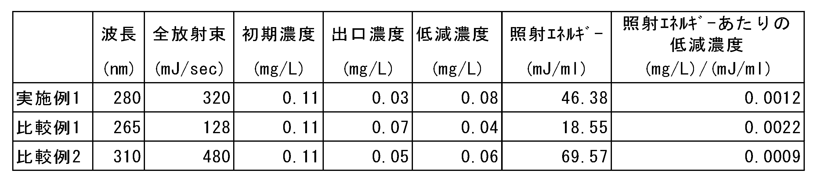
表3の結果から、LED光を照射する対象が海水ではなく淡水である場合には、比較例1のLED照射ユニットの照射エネルギー当たりの残留塩素低減濃度が最も大きく、海水を用いた場合と比較して、残留塩素を分解するエネルギー効率が高い光のピーク波長が異なる結果が確認された。
[残留塩素ゼロ海水作成試験]
上記天然海水試験と同様の条件で、ファラデーセルによりそれぞれ異なる電流の印加を行うことで、異なる残留塩素濃度の天然海水を調製した。流通する天然海水の流量を248ml/min(4.13ml/sec)とし、上記異なる残留塩素濃度の天然海水を実施例1に係るLED照射ユニットに流通させて、初期濃度、出口濃度から、低減濃度を算出した。結果を表4に示した。
上記天然海水試験と同様の条件で、ファラデーセルによりそれぞれ異なる電流の印加を行うことで、異なる残留塩素濃度の天然海水を調製した。流通する天然海水の流量を248ml/min(4.13ml/sec)とし、上記異なる残留塩素濃度の天然海水を実施例1に係るLED照射ユニットに流通させて、初期濃度、出口濃度から、低減濃度を算出した。結果を表4に示した。

表4の結果から、実施例1に係るLED照射ユニットを用いて、適切な照射エネルギーを海水に与えることで、残留塩素濃度が実質的にゼロの海水を作成できることが確認された。
1、1a 残留塩素自動分析計
10 光照射部
11 測定セル
C 電解セル(塩素生成部)
10 光照射部
11 測定セル
C 電解セル(塩素生成部)
Claims (6)
- 海水中の残留塩素を分析する残留塩素自動分析計であって、
前記海水中の残留塩素濃度を測定する測定セルと、
前記測定セルの上流側に設置され、前記測定セルに供給される前記海水に対して光を照射することで、前記海水中の残留塩素を分解し、実質的に残留塩素濃度がゼロの海水を生成可能な光照射部と、を備え、
前記光照射部から照射される光のピーク波長は、275~285nmの範囲内である、残留塩素自動分析計。 - 前記測定セルから流出する海水を前記測定セルに対して循環させるラインを有し、
前記光照射部は、前記残留塩素自動分析計内を循環する海水に対して光を照射することで、実質的に残留塩素濃度がゼロの海水を生成可能である、請求項1に記載の残留塩素自動分析計。 - 前記測定セルの上流側に設置され、塩素を生成する塩素生成部を備え、
前記塩素生成部は、前記海水を前記測定セルの上流側で電気分解することにより前記塩素を生成し、前記測定セルに供給する、請求項1又は2に記載の残留塩素自動分析計。 - 前記光照射部は、前記海水中の残留塩素濃度を0.03mg/L以下とすることができる、請求項1~3のいずれかに記載の残留塩素自動分析計。
- 測定時における前記海水中の残留塩素濃度は、0.1mg/L以下である、請求項1~4いずれかに記載の残留塩素自動分析計。
- 前記光照射部は、前記塩素生成部の上流側に設けられる、請求項3に記載の残留塩素自動分析計。
Priority Applications (3)
| Application Number | Priority Date | Filing Date | Title |
|---|---|---|---|
| PCT/JP2021/013999 WO2022208798A1 (ja) | 2021-03-31 | 2021-03-31 | 残留塩素自動分析計 |
| JP2021576359A JP7085075B1 (ja) | 2021-03-31 | 2021-03-31 | 残留塩素自動分析計 |
| TW111111375A TW202307425A (zh) | 2021-03-31 | 2022-03-25 | 殘留氯自動分析儀 |
Applications Claiming Priority (1)
| Application Number | Priority Date | Filing Date | Title |
|---|---|---|---|
| PCT/JP2021/013999 WO2022208798A1 (ja) | 2021-03-31 | 2021-03-31 | 残留塩素自動分析計 |
Publications (1)
| Publication Number | Publication Date |
|---|---|
| WO2022208798A1 true WO2022208798A1 (ja) | 2022-10-06 |
Family
ID=82019128
Family Applications (1)
| Application Number | Title | Priority Date | Filing Date |
|---|---|---|---|
| PCT/JP2021/013999 Ceased WO2022208798A1 (ja) | 2021-03-31 | 2021-03-31 | 残留塩素自動分析計 |
Country Status (3)
| Country | Link |
|---|---|
| JP (1) | JP7085075B1 (ja) |
| TW (1) | TW202307425A (ja) |
| WO (1) | WO2022208798A1 (ja) |
Citations (5)
| Publication number | Priority date | Publication date | Assignee | Title |
|---|---|---|---|---|
| JPH03165889A (ja) * | 1989-11-24 | 1991-07-17 | Ebara Infilco Co Ltd | 残留殺菌剤の除去方法 |
| JP2005283287A (ja) * | 2004-03-29 | 2005-10-13 | Horiba Ltd | ゼロ水精製部付き水質測定装置 |
| JP2007160241A (ja) * | 2005-12-15 | 2007-06-28 | Omega:Kk | 次亜ハロゲン酸の分解方法 |
| JP2016191605A (ja) * | 2015-03-31 | 2016-11-10 | 東亜ディーケーケー株式会社 | 残留塩素測定装置 |
| WO2021053752A1 (ja) * | 2019-09-18 | 2021-03-25 | 中国電力株式会社 | 残留塩素自動分析計 |
-
2021
- 2021-03-31 WO PCT/JP2021/013999 patent/WO2022208798A1/ja not_active Ceased
- 2021-03-31 JP JP2021576359A patent/JP7085075B1/ja active Active
-
2022
- 2022-03-25 TW TW111111375A patent/TW202307425A/zh unknown
Patent Citations (5)
| Publication number | Priority date | Publication date | Assignee | Title |
|---|---|---|---|---|
| JPH03165889A (ja) * | 1989-11-24 | 1991-07-17 | Ebara Infilco Co Ltd | 残留殺菌剤の除去方法 |
| JP2005283287A (ja) * | 2004-03-29 | 2005-10-13 | Horiba Ltd | ゼロ水精製部付き水質測定装置 |
| JP2007160241A (ja) * | 2005-12-15 | 2007-06-28 | Omega:Kk | 次亜ハロゲン酸の分解方法 |
| JP2016191605A (ja) * | 2015-03-31 | 2016-11-10 | 東亜ディーケーケー株式会社 | 残留塩素測定装置 |
| WO2021053752A1 (ja) * | 2019-09-18 | 2021-03-25 | 中国電力株式会社 | 残留塩素自動分析計 |
Also Published As
| Publication number | Publication date |
|---|---|
| JPWO2022208798A1 (ja) | 2022-10-06 |
| JP7085075B1 (ja) | 2022-06-15 |
| TW202307425A (zh) | 2023-02-16 |
Similar Documents
| Publication | Publication Date | Title |
|---|---|---|
| EP2178801B1 (en) | Method and system for treating ballast water | |
| US8591740B2 (en) | Method and system for biofouling control of shipboard components | |
| US11629067B1 (en) | Ocean alkalinity system and method for capturing atmospheric carbon dioxide | |
| US12084363B2 (en) | Ballast water management system | |
| CN102105406A (zh) | 压舱水处理装置及方法 | |
| JP2015208735A (ja) | 排ガスの処理方法及び処理装置 | |
| CN112368418B (zh) | 臭氧水生成系统 | |
| WO2022208798A1 (ja) | 残留塩素自動分析計 | |
| CN107001076A (zh) | 氨处理系统 | |
| KR101614585B1 (ko) | 선박 평형수 처리 시스템의 전해조 해수 공급장치 | |
| JP5265458B2 (ja) | 海水中co2濃度測定装置及び藻類育成システム | |
| JP2007307502A (ja) | 電解水の生成方法および電解水の生成器 | |
| KR102077136B1 (ko) | 총인 및 총질소 측정장치 | |
| JP2016087582A (ja) | 電解システム | |
| KR101163344B1 (ko) | 전기분해 유닛을 이용한 선박의 발라스트 수 처리방법 | |
| Castro Castro et al. | Treatment of effluent from municipal wastewater treatment plants using electrochemically produced Caros acid | |
| JP4381178B2 (ja) | 電解殺菌水の製造装置 | |
| JP6222651B2 (ja) | 酸化態窒素濃度の測定方法及び測定装置 | |
| JP2017063667A (ja) | 循環型養殖方法及び循環型養殖装置 | |
| JP2008073652A (ja) | 廃液処理装置、及び廃液処理方法 | |
| JPH01315385A (ja) | 構造水製造装置 |
Legal Events
| Date | Code | Title | Description |
|---|---|---|---|
| ENP | Entry into the national phase |
Ref document number: 2021576359 Country of ref document: JP Kind code of ref document: A |
|
| 121 | Ep: the epo has been informed by wipo that ep was designated in this application |
Ref document number: 21934963 Country of ref document: EP Kind code of ref document: A1 |
|
| NENP | Non-entry into the national phase |
Ref country code: DE |
|
| 122 | Ep: pct application non-entry in european phase |
Ref document number: 21934963 Country of ref document: EP Kind code of ref document: A1 |