WO2022208744A1 - 中空屈曲部材の製造方法及び中空屈曲部材の製造装置 - Google Patents
中空屈曲部材の製造方法及び中空屈曲部材の製造装置 Download PDFInfo
- Publication number
- WO2022208744A1 WO2022208744A1 PCT/JP2021/013878 JP2021013878W WO2022208744A1 WO 2022208744 A1 WO2022208744 A1 WO 2022208744A1 JP 2021013878 W JP2021013878 W JP 2021013878W WO 2022208744 A1 WO2022208744 A1 WO 2022208744A1
- Authority
- WO
- WIPO (PCT)
- Prior art keywords
- hollow
- hollow material
- heating
- cooling
- shearing
- Prior art date
- Legal status (The legal status is an assumption and is not a legal conclusion. Google has not performed a legal analysis and makes no representation as to the accuracy of the status listed.)
- Ceased
Links
Images





Classifications
-
- B—PERFORMING OPERATIONS; TRANSPORTING
- B21—MECHANICAL METAL-WORKING WITHOUT ESSENTIALLY REMOVING MATERIAL; PUNCHING METAL
- B21D—WORKING OR PROCESSING OF SHEET METAL OR METAL TUBES, RODS OR PROFILES WITHOUT ESSENTIALLY REMOVING MATERIAL; PUNCHING METAL
- B21D7/00—Bending rods, profiles, or tubes
-
- B—PERFORMING OPERATIONS; TRANSPORTING
- B21—MECHANICAL METAL-WORKING WITHOUT ESSENTIALLY REMOVING MATERIAL; PUNCHING METAL
- B21D—WORKING OR PROCESSING OF SHEET METAL OR METAL TUBES, RODS OR PROFILES WITHOUT ESSENTIALLY REMOVING MATERIAL; PUNCHING METAL
- B21D7/00—Bending rods, profiles, or tubes
- B21D7/16—Auxiliary equipment, e.g. for heating or cooling of bends
Definitions
- the present invention relates to a hollow bending member manufacturing method and a hollow bending member manufacturing apparatus.
- Metal members with a hollow, bent shape are used as strength members, reinforcing members, or structural members for automobiles, various machines, and the like.
- This hollow bending member is required to be lightweight and have high strength.
- this type of hollow bending member has been manufactured by, for example, cold bending, welding of press work, stamping of thick plate, or forging.
- these manufacturing methods have limitations in reducing the weight and increasing the strength of the manufactured hollow bending member.
- Patent Document 3 In recent years, as disclosed in Patent Document 3 and the like, manufacturing hollow bending members by a tube hydroforming method has been studied. However, since the tube hydroforming method is cold forming, there is a limit to the forming of high-strength materials.
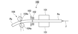
- FIG. 8 is an explanatory diagram showing an outline of this bending apparatus 100.
- a hollow metal material Pm is fed in the direction of an arrow F and bent by a roller die 104 arranged downstream to manufacture a hollow bending member Pp. . That is, at the downstream position of the support means 101, the high-frequency heating coil 102 rapidly heats the hollow material Pm to a temperature range where partial quenching is possible, and the water-cooling device 103 arranged downstream of the high-frequency heating coil 102 cools the hollow material Pm. quench.
- the roller die 104 that feeds the hollow material Pm while supporting it is moved three-dimensionally (or two-dimensionally in some cases) to apply a bending moment to the heated portion of the hollow material Pm, thereby bending process.
- this bending apparatus 100 it is possible to manufacture a high-strength hollow bending member Pp with high work efficiency.
- Hollow bending members used in automobiles, various machines, etc. have various shapes. There are a variety of hollow bending members having bends whose bending radius is, for example, 1 to 2 times or less than the diameter of the metal tube (the length of the side in the bending direction in the case of a rectangular cross section).
- the diameter of the metal tube the length of the side in the bending direction in the case of a rectangular cross section.
- this shearing device 200 comprises first support means 201 , heating means 202 , cooling means 203 and gripping means 204 .
- the first support means 201 supports the hollow metal material Pm at position A1 while relatively feeding it in its longitudinal direction.
- the heating means 202 partially heats the hollow material Pm at the position B1.
- the cooling means 203 cools the heated portion of the hollow material Pm at position C1 downstream of position B1.
- the gripping means 204 moves the gripping portion in two-dimensional or three-dimensional directions while positioning the hollow material Pm at the position D1 downstream of the position C1, thereby applying a shearing force to the heated portion of the hollow material Pm. give. Thereby, a sheared portion is formed and a hollow bending member is obtained.
- the shearing device 200 it is possible to perform shearing and heat treatment (quenching by cooling) on the heated portion of the hollow material Pm. Further, according to the shearing device 200, it is possible to reliably mass-produce high-strength hollow bending members having bent portions with small bending radii at low cost.
- an induction heating coil 301 and a cooling water injection nozzle 302 are arranged to be inclined with respect to the longitudinal direction of the hollow material Pm, which is a square tube, so that the hollow material Pm by the shearing process is It is disclosed to prevent wall thickness reduction. That is, referring to FIG. 10, when the plate thickness of the hollow material Pm before processing is t0 and the shearing angle is ⁇ , shearing is performed by arranging the induction heating coil 301 without providing the inclination. In this case, the plate thickness after shearing is t 0 ⁇ cos ⁇ . On the other hand, it is disclosed that when shearing is performed with the induction heating coil 301 inclined, the plate thickness after shearing can be kept at t0 .
- Patent Literature 2 discloses a shearing device 300 in which an induction heating coil 301 and a cooling water injection nozzle 302 are arranged obliquely with respect to the longitudinal direction of the hollow material Pm. If the shearing device 300 continuously performs upward shearing and downward shearing in the figure, heating and cooling during downward shearing become uneven. . If the heating and cooling are uneven, the resulting hollow flexure may not have the required properties.
- the present invention has been made in view of the above circumstances, and is a manufacturing method that enables integral manufacture of a hollow bending member having a U-shape or a shape similar thereto without requiring an additional welding process or the like. and to provide manufacturing equipment.
- a method for manufacturing a hollow bending member comprises: a feeding step of feeding a long metal hollow material in a feeding direction, which is the longitudinal direction of the hollow material, while being supported at a first position; a heating step of partially heating the hollow material at a second position downstream of the first position to form a heating portion; a cooling step of cooling at least part of the hollow material positioned downstream of the heating section at a third position downstream of the second position to form a cooling section; a shearing step of gripping the hollow material at a fourth position downstream of the third position and moving the gripped portion of the hollow material in two-dimensional or three-dimensional directions; has A first sheared portion is formed by a first series of steps including the feeding step, the heating step, the cooling step, and the shearing step, A second sheared portion is formed by a second series of steps including the feeding step, the heating step, the cooling step, and the shearing step
- the second series of steps may include a step selected from the following (A) or (B).
- A) The heating and the cooling are performed at an inclination angle in a second direction different from the first direction with respect to a plane perpendicular to the feeding direction.
- B) The heating and cooling are performed after the hollow material is rotated about the central axis of the hollow material in the longitudinal direction.
- An apparatus for manufacturing a hollow bending member includes: feeding means for feeding a long metal hollow material in a feeding direction, which is the longitudinal direction of the hollow material, while supporting the hollow material at a first position; heating means for partially heating the hollow material at a second position downstream of the first position to form a heating portion; cooling means for cooling at least part of the hollow material positioned downstream of the heating section at a third position downstream of the second position to form a cooling section; shearing means for gripping the hollow material at a fourth position downstream of the third position and moving the gripped portion of the hollow material in two-dimensional or three-dimensional directions; has forming a first shearing portion by a first series of means including the feeding means, the heating means, the cooling means, and the shearing means; A second sheared portion is formed by a second series of means including the feeding means, the heating means, the cooling means, and the shearing means, In the first series of means, the heating and the cooling are performed at an inclination angle in the first direction
- a means selected from the following (A) or (B) may be provided.
- the heating and the cooling are performed at an inclination angle in a second direction different from the first direction with respect to a plane perpendicular to the feeding direction.
- the heating and cooling are performed after the hollow material is rotated about the central axis of the hollow material in the longitudinal direction.
- the apparatus for manufacturing a hollow bending member according to (7) above In the shearing means, when viewed in a cross section including the central axis of the hollow material, the gripping portion is moved in an inclined direction between the feed direction and a direction orthogonal to the feed direction, and the central axis is moved. It may not be rotated around the axis orthogonal to , or may be rotated by suppressing the amount of rotation required for normal bending deformation.
- the hollow bending member manufacturing apparatus according to (7) or (8) above, The heating means may have a substantially parallel portion facing the hollow material in a cross-sectional shape including the central axis along the longitudinal direction of the hollow material.
- the shearing means may comprise a plurality of gripping means for gripping the hollow material.
- hollow bending member manufacturing method and manufacturing apparatus it is possible to integrally manufacture a hollow bending member having a U-shape or a shape similar thereto without requiring an additional welding process or the like. Obviously, it is possible to integrally manufacture a hollow bending member having a U-shape or a shape similar thereto without requiring an additional welding process or the like. Obviously, it is possible to integrally manufacture a hollow bending member having a U-shape or a shape similar thereto without requiring an additional welding process or the like. Become.
- FIG. 4 is a diagram showing the external shape of a hollow bending member manufactured by the same manufacturing method using the same manufacturing apparatus, in which (a) is a U-shaped part, (b) is a U-shaped part having an opening angle, and (c) indicates a component that is substantially U-shaped and has two bent portions Pa and Pb between two bent portions P1 and P2.
- FIG. 4 is a diagram showing the external shape of a hollow bending member manufactured by the same manufacturing method using the same manufacturing apparatus, in which (a) is a U-shaped part, (b) is a U-shaped part having an opening angle, and (c) indicates a component that is substantially U-shaped and has two bent portions Pa and Pb between two bent portions P1 and P2.
- FIG. 4 is a vertical cross-sectional view schematically showing an apparatus and method for manufacturing a hollow bending member according to a second embodiment of the present invention, in which shearing is performed in the order of steps (a) to (d).
- FIG. 10 is a vertical cross-sectional view schematically showing a hollow bending member manufacturing apparatus and manufacturing method according to a third embodiment of the present invention, in which shearing is performed in the order of steps (a) to (d).
- FIG. 10 is a vertical cross-sectional view schematically showing a hollow bending member manufacturing apparatus and manufacturing method according to a fourth embodiment of the present invention, in which shearing is performed in the order of steps (a) to (e).
- FIG. 10 is a longitudinal sectional view schematically showing a hollow bending member manufacturing apparatus and manufacturing method according to a fifth embodiment of the present invention.
- FIG. 10(a) to (c) are perspective views showing other examples of the hollow bending member manufactured in each embodiment of the present invention.
- 1 is an explanatory diagram showing a schematic configuration of a bending apparatus disclosed in Patent Document 1;
- FIG. It is an explanatory view showing a schematic configuration of a shearing device disclosed in Patent Document 2.
- FIG. 11 is an explanatory diagram showing a schematic configuration of another shearing device disclosed in Patent Document 2;
- a hollow bending member Pp using a hollow steel square tube having a rectangular cross-sectional shape as a material (hereinafter referred to as a hollow material Pm) will be described as an example.
- manufacturing apparatus 10 an apparatus for manufacturing a hollow bending member (hereinafter referred to as manufacturing apparatus 10) to which the present manufacturing method is applied will be described first, and then the manufacturing method will be described.
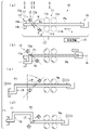
- FIG. 1 is an explanatory diagram schematically showing a manufacturing apparatus 10 according to the present embodiment and a method for manufacturing a hollow bending member using the manufacturing apparatus 10.
- the manufacturing apparatus 10 shears the hollow material Pm to obtain the hollow bending member Pp.
- the hollow material Pm is a long rectangular steel tube having a hollow rectangular closed cross-sectional shape perpendicular to its longitudinal direction.
- the hollow material Pm to be processed in the present embodiment is not limited to a square tube, and may be, for example, a tube having a circular, elliptical, or various irregular cross-sectional shape.
- the hollow material Pm having a rectangular cross section may have either a square cross section or a rectangular cross section.
- the hollow material Pm may be a metal pipe other than a steel pipe.
- the manufacturing apparatus 10 includes a support device 11, a heating device 12, a cooling device 13, a shearing force application device 14, a control device 15, and a feeding device 19.
- Support device 11 The support device 11 includes a plurality (two sets in the example of FIG. 1) of rolls 11a and 11b. A set of rolls 11a sandwich and support the hollow material Pm therebetween. Similarly, a set of rolls 11b also support the hollow material Pm by sandwiching it therebetween. Another set of rolls 11a is arranged adjacent to the downstream position of the set of rolls 11b. The hollow material Pm is supported at the first position A by these rolls 11a and 11b.
- the support device 11 may support the hollow material Pm so that it can be fed along the feed direction, and a support device having other configurations may be employed.
- the support device 11 is fixedly arranged on a mounting table (not shown). However, it is not limited to this aspect, and for example, the support device 11 may be supported by an end effector (not shown) of an industrial robot.
- the supporting device 11 is synchronized with the shearing force applying device 14 and the feeding device 19 as indicated by the arrow in FIG. It may be configured to rotate to
- the feeding device 19 feeds the hollow material Pm supported by the supporting device 11 in its longitudinal direction (leftward direction on the paper surface along arrow F) at a predetermined feeding speed.
- the feeding device 19 is exemplified by a type using an electric servo cylinder, but it is not limited to a specific type, and a type using a ball screw, a type using a timing belt or a chain, or the like can also be adopted. After the portion where the support device 11 is installed passes the first position A, the hollow material Pm is further fed in the arrow F direction by the feeding device 19 .
- the feeding device 19 is synchronized with the supporting device 11 and the shearing force applying device 14 as indicated by the arrow in FIG. It may be configured to rotate to As a result, the hollow material Pm can be rotated around the center axis CL in the longitudinal direction of the hollow material Pm.
- Heating device 12 The heating device 12 is arranged to perform heating at a second position B which is downstream from the first position A in the feed direction of the hollow material Pm.
- the heating device 12 heats the entire circumference of the cross section of the hollow material Pm sent through the support device 11 in a part of the longitudinal direction.
- An induction heating device is used as the heating device 12 .
- This induction heating device has a coil capable of heating the hollow material Pm by high frequency induction, for example.
- the heating coil 12a of the heating device 12 is arranged at a predetermined distance from the outer surface of the hollow material Pm so as to surround the entire circumference of the cross section in a part of the longitudinal direction of the hollow material Pm.
- the hollow material Pm is partially rapidly heated by the heating device 12 .
- the installation means (not shown) of the heating device 12 can arrange the heating coil 12a at the second position B so that the inclination angle can be adjusted. That is, the installation means of the heating device 12 includes a rotating means (not shown) for tilting the heating coil 12a at a set angle with respect to the feeding direction of the hollow material Pm.
- the inclination direction of the heating coil 12a is set to L1.
- the heating coil 12a is inclined so as to intersect the longitudinal direction of the hollow material Pm (the feeding direction of the hollow material Pm indicated by arrow F) at an angle of inclination ⁇ when viewed from the side.
- This inclination angle ⁇ is an angle formed by a direction perpendicular to the longitudinal direction (extending direction of straight line L2) and L1.
- the direction of this inclination angle ⁇ is a positive direction toward the feeding direction of the hollow material Pm. More specifically, as shown in (a) of FIG. 1, when viewed in a longitudinal section including the center line of the heating coil 12a, the direction of the straight line L2 passing through the center position of the heating coil 12a and the direction of the central axis CL of the hollow material Pm By rotating (inclining) the heating coil 12a around this rotation axis by using the rotating means, the inclination angle can be set to ⁇ .
- the tilt angle can be reversed to - ⁇ .
- the direction of this inclination angle - ⁇ is a negative direction that is opposite to the feeding direction of the hollow material Pm.
- the upper portion of the heating coil 12a which was tilted to the left side of the paper surface (positive tilt direction) in FIG. 1(b), is tilted to the right side of the paper surface (negative tilt direction) as shown in FIG. can be done. This makes it possible to reverse the inclination angle of the heating coil 12a from ⁇ to - ⁇ .
- the cross-sectional shape of the heating coil 12a of the heating device 12 is preferably circular when the hollow material Pm is a round tube. Specifically, it is preferable that the projected shape of the heating coil 12a when viewed from the central axis CL along the longitudinal direction of the hollow material Pm is concentric with the hollow material Pm and has a uniform clearance. Thereby, when the heating coil 12a is inclined at a positive inclination angle or a negative inclination angle, the outer peripheral surface of the hollow material Pm heated by the heating coil 12a can be efficiently heated.
- the projection shape of the heating coil 12a when viewed from the central axis CL along the longitudinal direction of the hollow material Pm provides a clearance suitable for heating with the hollow material Pm. It is preferable to have a shape with The same applies to the second, fourth, and fifth embodiments, which will be described later.
- the heating device 12 As an installation means for the heating device 12, for example, a well-known end effector of an industrial robot can be exemplified. A single-arm robot or an off-the-shelf device having an arm and a motor can also be adopted.
- the adjustment of the inclination angle ⁇ by the installation means of the heating device 12 may be automatically controlled by the installation means receiving a control signal from the control device 15 .
- the installation means receiving a control signal from the control device 15 .
- the installation means receiving a control signal from the control device 15 .
- the relationship between the shearing position and the inclination angle ⁇ to be set at the same position is stored in advance in the control device 15, and the feeding amount of the hollow material Pm is set to a predetermined value.
- one or more preheating devices capable of preheating the hollow material Pm are arranged upstream of the heating device 12 along the feed direction of the hollow material Pm. can be used together with the heating device 12 to heat the hollow material Pm. In this case, it becomes possible to heat the hollow material Pm multiple times.
- Cooling device 13 The cooling device 13 is arranged to perform cooling at a third position C downstream of the second position B along the feeding direction of the hollow material Pm.
- the cooling device 13 rapidly cools at least a portion of the hollow material Pm located downstream of the portion heated at the second position B.
- the region between the first portion (heating portion) heated by the heating device 12 and the second portion (cooling portion) cooled by the cooling device 13 is heated to a high temperature. There is a state in which the deformation resistance is greatly reduced.
- the cooling device 13 is not limited to a specific type of cooling device as long as a desired cooling rate can be obtained. Generally, it is desirable to use a water cooling device that cools the hollow material Pm by injecting cooling water toward a predetermined position on the outer peripheral surface of the hollow material Pm.
- a large number of cooling water injection nozzles 13a are arranged immediately downstream of the heating device 12 so as to surround a portion of the cross section in the longitudinal direction of the hollow material Pm, separated from the outer surface of the hollow material Pm. is doing. From these cooling water injection nozzles 13a, cooling water is injected toward the outer surface of the hollow material Pm.
- the cooling water is preferably sprayed obliquely in the direction in which the hollow material Pm is delivered so as not to hinder the heating of the hollow material Pm by the heating device 12 .
- the distance between each cooling water injection nozzle 13a and the hollow material Pm is changed and set in a cross section orthogonal to the direction of the central axis CL of the hollow material Pm, the central axis CL of the hollow material Pm is cooled. A region of directions can be adjusted.
- the cooling device 13 By appropriately adjusting the starting temperature and cooling rate of water cooling by the cooling device 13, it is possible to harden or anneal part or all of the rapid cooling portion in the hollow material Pm. This makes it possible to significantly increase the strength of part or all of the curved portion of the hollow material Pm to, for example, 1500 MPa or more.
- the installation means of the cooling device 13 is not limited to a specific installation means as long as the cooling device 13 can be arranged at the third position C.
- the distance between the second position B and the third position C is set as short as possible so that the heating device 12 It is desirable to set the area between the first portion (heating portion) heated by the heat and the second portion (cooling portion) cooled by the cooling device 13 as small as possible. For this purpose, it is desirable to dispose the cooling water injection nozzle 13a close to the heating coil 12a. Therefore, it is desirable to arrange the cooling water injection nozzle 13a at a position immediately after the heating coil 12a.
- cooling device 13 may be fixed to the installation means of the heating device 12 .
- both the cooling water injection nozzles 13a and the heating coils 12a can be tilted at the same angle while maintaining the relative positional relationship between the cooling water injection nozzles 13a and the heating coils 12a.
- the installation means for the cooling device 13 may be provided separately from the installation means for the heating device 12 .
- the installation means (not shown) of the cooling device 13 can arrange each cooling water injection nozzle 13a at the third position C so that the inclination angle can be adjusted. That is, the installation means of the cooling device 13 can tilt the cooling device 13 at a set angle with respect to the feeding direction of the hollow material Pm.
- each cooling element is arranged so as to intersect the longitudinal direction of the hollow material Pm (the feeding direction of the hollow material Pm, indicated by arrow F) at a positive inclination angle ⁇ in a side view.
- the water injection nozzle 13a can be arranged at an angle.
- each cooling water injection nozzle 13a By synchronizing the inclination angle of each cooling water injection nozzle 13a with the inclination angle of the heating coil 12a and always making it the same, each cooling water injection nozzle 13a can be arranged adjacently without interfering with the heating coil 12a. becomes possible.
- the adjustment of the inclination angle by the installation means of the cooling device 13 is performed by rotating means (not shown) provided in the installation means.
- the rotating means can arrange each cooling water injection nozzle 13a at the third position C so that the inclination angle can be adjusted.
- the rotating means inclines each cooling water injection nozzle 13a at a set angle with respect to the feeding direction of the hollow material Pm.
- each cooling water injection nozzle 13a By rotating (tilting) each cooling water injection nozzle 13a by the rotating means, the tilt angle can be set to a positive tilt angle ⁇ , as shown in FIG. 1(a). In addition, by rotating (tilting) each cooling water injection nozzle 13a in the opposite direction by the rotating means, the tilt angle is reversed to a negative tilt angle ⁇ as shown in FIG. 1(c).
- an end effector of a conventional industrial robot can be exemplified, but other installation means may be adopted as long as the inclination angle ⁇ can be adjusted as specified.
- a ready-made device having a single-arm robot or a rotating means such as an arm and a motor can also be adopted.
- the adjustment of the inclination angle ⁇ by the mounting means of the cooling device 13 may be automatically controlled by receiving a control signal from the control device 15 by the rotating means of the cooling device 13 .
- Shear force application device 14 The shearing force applying device 14 is arranged at a fourth position D downstream of the third position C along the feeding direction of the hollow material Pm. The shearing force applying device 14 moves in two-dimensional or three-dimensional directions while positioning the hollow material Pm.
- the shearing force applying device 14 causes a gap between the first portion (heating portion) heated by the heating device 12 and the second portion (cooling portion) cooled by the cooling device 13 in the hollow material Pm.
- a shearing force is applied to at least a part of the region of to shear the hollow material Pm.
- This gripping position movement does not rotate the hollow material Pm about an axis perpendicular to the central axis CL.
- the movement of the gripping position is accompanied by the rotation, and the amount of rotation is suppressed from the amount of rotation required for normal bending deformation.
- the amount of rotation is preferably 50% or less of the amount of rotation required for normal bending deformation. If the movement of the gripping position for gripping the hollow material Pm does not accompany any rotation of the central axis CL of the hollow material Pm about the orthogonal axis, complete shearing is performed.
- the shearing force applying device 14 comprises one or a plurality of upper and lower gripping means 14a, 14b. These gripping means 14a and 14b determine the gripping position of the hollow material Pm by contacting the outer surface or the inner surface of the hollow material Pm.
- the shear angle ⁇ can be adjusted by adjusting the gripping position. This shear angle ⁇ is the angle between the central axis CL of the hollow material Pm and the central axis of the hollow material Pm after passing through the cooling device 13 on a virtual plane including the straight lines L1 and L2.
- the pair of upper and lower gripping means 14a and 14b are supported by a support frame (not shown).
- the support frame is held by a moving mechanism (also not shown) that holds the support frame movably in two-dimensional or three-dimensional directions.
- the pair of upper and lower gripping means 14a and 14b are used as rolls, and the hollow material Pm after passing through the shearing force applying device 14 is placed at a position downstream of the installation position of the shearing force applying device 14 along the feeding direction of the hollow material Pm.
- a supporting device (not shown) for supporting may be further provided. In this case, it becomes possible to manufacture the hollow bending member Pp with higher dimensional accuracy.
- a cross section of the hollow material Pm at a part in the longitudinal direction is heated by the heating device 12 and the deformation resistance is greatly reduced.
- the position of the pair of upper and lower gripping means 14a, 14b can be moved two-dimensionally or three-dimensionally at a fourth position D downstream of the third position C along the feed direction of the hollow material Pm.
- the first portion (heating portion) heated by the heating device 12 and the second portion (cooling portion) cooled by the cooling device 13 A shear force Ws can be applied to the region between A bending portion P1 is formed as shown in FIG. 1(b) by the shearing force Ws acting on the hollow material Pm.
- a shear force is applied to the heated portion of the hollow material Pm instead of applying a bending moment to the heated portion of the hollow material Pm as in the invention disclosed in Patent Document 1. Therefore, it is possible to manufacture a Pp having a bending portion with an extremely small bending radius, for example, 1 to 2 times or less than the diameter of the metal pipe (the length of the side in the bending direction in the case of a rectangular cross section). can. Further, while the hollow material Pm is linearly quenched in the direction parallel to the central axis CL by the rotating means described above, the inclination direction of the heating coil 12a and the cooling water injection nozzle 13a is changed from the positive direction ( ⁇ ).
- the shearing force applying device 14 may be installed via a mechanism capable of disposing a pair of upper and lower gripping means 14a and 14b so as to be movable in two-dimensional or three-dimensional directions as described above. Such mechanisms are not particularly limited.
- an end effector of an industrial robot may hold the support frames of the pair of upper and lower gripping means 14a and 14b.
- the shearing force applying device 14 is synchronized with the supporting device 11 and the feeding device 19 as indicated by the arrow in FIG. It may be configured to rotate to Thereby, the hollow material Pm can be rotated around the central axis CL.
- Control device 15 controls various operations of the support device 11, the heating device 12, the cooling device 13, the shearing force applying device 14, and the feeding device 19 described above.
- the control device 15 sets the inclination angle ⁇ of the heating device 12 and the cooling device 13 with respect to the feeding direction, and controls the heating device 12, the cooling device 13, the shearing force applying device 14, and the feeding device 19 based on the setting. . This makes it possible to adjust the shearing angle formed before and after applying the shearing force along the feed direction to the hollow material Pm.
- a method of manufacturing the hollow bending member Pp from the hollow material Pm using the manufacturing apparatus 10 will be described below.
- a manufacturing apparatus 10 is used to manufacture the hollow bending member Pp shown in FIG.
- This hollow bending member Pp has two bending portions P1 and P2 each forming an angle of 90 degrees.
- a hollow material Pm which is a straight metal hollow tube
- a manufacturing apparatus 10 As shown in FIG. That is, the hollow material Pm is supported by the supporting device 11 at the first position A, the rear end side of the hollow material Pm is fixed to the feeding device 19, and the leading end side of the hollow material Pm is gripped by the shearing force applying device 14. .
- the heating coil 12a of the heating device 12 is arranged at a second position B downstream from the first position A, and the cooling water injection nozzles 13a of the cooling device 13 are arranged at a third position C downstream from the second position B. place it.
- the heating coil 12a and the cooling water injection nozzles 13a are arranged at an inclination such that the angle of inclination is a positive angle of inclination ⁇ by the rotating means. With this arrangement, heating and cooling are performed with an inclination angle ⁇ in the first direction with respect to a plane perpendicular to the feed direction. Under the above settings, heating of the hollow material Pm by the heating device 12 is started.
- the hollow material Pm is partially heated at the second position B ( heating step), cooling at least a portion of the hollow material Pm located downstream of the heating section at a third position C (cooling step), and cooling the hollow material at a fourth position D downstream of the third position C.
- Pm is gripped, and the gripped portion is moved in two-dimensional or three-dimensional directions by the shearing force applying device 14 (shearing process).
- the gripping position of the shearing force applying device 14 when the gripping position of the shearing force applying device 14 is viewed in a cross section including the central axis CL of the hollow material Pm, the feeding direction along the longitudinal direction of the hollow material Pm and the feeding direction of the hollow material Pm. It is moved in an oblique direction between the direction orthogonal to the longitudinal direction and is not rotated around the axis orthogonal to the central axis CL of the hollow material Pm, or is rotated by suppressing the amount of rotation required for normal bending deformation. .
- the amount of rotation is preferably 50% or less of the amount of rotation required for normal bending deformation. In this embodiment, as shown in FIG.
- the shearing force applying device 14 is lowered downward perpendicular to the direction of the central axis CL to perform the first shearing process, thereby performing the bending portion P1.
- the bending angle (shearing angle ⁇ ) of this bending portion P1 is a right angle (90 degrees), and since it is cooled by cooling water from each cooling water injection nozzle 13a, quenching is also performed at the same time.
- the first sheared portion 16 is formed through the first series of steps including the feeding step, heating step, cooling step, and shearing step.
- the hollow material Pm has a 90-degree bent portion formed immediately adjacent to the shearing force applying device 14 and the 90-degree bent portion P1 formed on the rear side of the bent portion. is formed.
- the heating coil 12a and the cooling water injection nozzles 13a are rotated by the rotating means while the linear portion is being quenched, and the heating coil 12a and the cooling water injection nozzles 13a are rotated from FIG. 1(b) to FIG. 1(c). rotate to As a result, as shown in (c) of FIG. 1, the inclination angles of the heating coil 12a and the cooling water injection nozzles 13a are changed to a negative inclination angle of - ⁇ . That is, the relative inclination angles of the heating coil 12a and the cooling water injection nozzles 13a with respect to the hollow material Pm are changed around the horizontal axis. Thus, heating and cooling are performed at an inclination angle in the second direction different from the first direction with respect to the plane perpendicular to the feeding direction.
- the hollow material Pm is gripped at a fourth position D downstream of the third position C, and the shearing force applying device 14 is moved two-dimensionally or three-dimensionally.
- Move (shearing process) Specifically, while the inclination angles of the heating coil 12a and the cooling water injection nozzles 13a are fixed to ⁇ set in the process of FIG. A second shearing process is performed by moving upward in an orthogonal direction to form the bent portion P2.
- the bending angle (shearing angle ⁇ ) of this bending portion P2 is a right angle (90 degrees), and since it is cooled by the cooling water from each cooling water injection nozzle 13a, quenching is also performed at the same time. Therefore, good thermomechanical processing can be performed at the shearing positions of both the bent portions P1 and P2.
- the second sheared portion 17 is formed through the second series of steps including the feeding step, heating step, cooling step, and shearing step.
- the inclination angles of the heating coil 12a and the cooling water injection nozzles 13a are a positive inclination angle ⁇ . After heating and cooling by tilting in advance, shearing is performed. Therefore, since the heating coil 12a and the cooling water injection nozzles 13a are arranged at an angle so as to avoid interference with the hollow material Pm, excellent shearing can be performed without difficulty.
- the inclination angles of the heating coil 12a and the cooling water injection nozzles 13a are reversed in advance so that the inclination angles of the heating coil 12a and the cooling water injection nozzles 13a become negative inclination angles - ⁇ .
- the hollow material Pm, the heating device 12, and the cooling device 13 are in the same relative positional relationship, so the same heating and cooling are performed, resulting in a good product. Quality can be achieved. Furthermore, since the heating coil 12a and the cooling water injection nozzles 13a are arranged at an angle so as to avoid interference with the hollow material Pm, excellent shearing can be performed without difficulty.
- the hollow bending member Pp shown in FIG. 2(a) can be obtained by cutting off unnecessary portions from the hollow material Pm after the shearing process.
- the bending angles at the bending portions P1 and P2 are not limited to right angles (90 degrees).
- the control device 15 adjusts the operation of the shear force applying device 14, the inclination angles of the heating coil 12a and the cooling water injection nozzle 13a, and the feed rate of the feed device 19, for example, as shown in FIG. 2(b). It is also possible to obtain a U-shaped hollow bending member Pp with such an opening angle. Furthermore, it is also possible to obtain a hollow bending member Pp similar to a U-shape, as shown in FIG. 2(c).
- the hollow bending member Pp shown in FIG. 2(c) is substantially U-shaped and has two bending portions Pa and Pb between two bending portions P1 and P2.
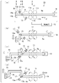
- FIG. 3(a) shows a hollow bending member manufacturing apparatus (hereinafter referred to as a manufacturing apparatus 20) according to the present embodiment.
- the manufacturing apparatus 20 of the present embodiment is particularly different from the manufacturing apparatus 10 of the first embodiment in that the rotating means for adjusting the inclination angle of the heating coil 12a and the cooling water injection nozzles 13a for adjusting the inclination angle of the cooling water injection nozzles 13a are described. Rotating means.
- the rotating means for the heating coil 12a rotates the heating coil 12a around the longitudinal direction of the hollow material Pm (feeding direction along the central axis CL). More specifically, by rotating the heating coil 12a around its central axis CL by the rotating means, the upper portion of the heating coil 12a that was on the upper side of the paper surface in FIG. can be on the bottom side of the paper as shown. This makes it possible to reverse the tilt angle of the heating coil 12a from the positive tilt angle ⁇ to the negative tilt angle ⁇ .
- the rotating means of the cooling device 13 in this embodiment can rotate the arrangement of the cooling water injection nozzles 13a around the longitudinal direction of the hollow material Pm (feeding direction along the central axis CL). is. More specifically, by rotating the arrangement of the cooling water injection nozzles 13a around their central axis CL by the rotating means, the cooling water injection nozzles 13a located on the upper side of the paper surface in FIG. As shown in (c) of FIG. 3, it can be arranged on the lower side of the paper surface. This makes it possible to reverse the inclination angle of each cooling water injection nozzle 13a.
- each cooling water injection nozzle 13a may be integrated with the heating coil 12a, and the cooling water injection nozzle 13a and the heating coil 12a may be rotated only by means for rotating the heating coil 12a.
- a hollow material Pm which is a straight hollow pipe made of metal, is set in the manufacturing apparatus 10 . That is, the hollow material Pm is supported by the supporting device 11 at the first position A, the rear end side of the hollow material Pm is fixed to the feeding device 19, and the leading end side of the hollow material Pm is gripped by the shearing force applying device 14. .
- the heating coil 12a of the heating device 12 is arranged to perform heating at a second position B downstream from the first position A, and the cooling device 13 to perform cooling at a third position C downstream from the second position B. , each cooling water injection nozzle 13a.
- the heating coil 12a and the cooling water injection nozzles 13a are arranged at an inclination such that the angle of inclination is a positive angle of inclination ⁇ by the rotating means. With this arrangement, heating and cooling are performed with an inclination angle ⁇ in the first direction with respect to a plane perpendicular to the feeding direction. Under the above settings, heating of the hollow material Pm by the heating device 12 is started.
- the hollow material Pm is partially heated at the second position B ( heating step), cooling at least a portion of the hollow material Pm located downstream of the heating section at a third position C (cooling step), and cooling the hollow material at a fourth position D downstream of the third position C.
- Pm is gripped and the shearing force applying device 14 is moved in two-dimensional or three-dimensional directions (shearing process).
- the gripping position of the shearing force applying device 14 when the gripping position of the shearing force applying device 14 is viewed in a cross section including the central axis CL of the hollow material Pm, the feed direction along the longitudinal direction of the hollow material Pm and the direction of the hollow material Pm. It is moved in an oblique direction between the direction orthogonal to the longitudinal direction and is not rotated around the axis orthogonal to the central axis CL of the hollow material Pm, or is rotated by suppressing the amount of rotation required for normal bending deformation. .
- the amount of rotation is preferably 50% or less of the amount of rotation required for normal bending deformation. In this embodiment, as shown in (b) of FIG.
- the shearing force applying device 14 is lowered downward perpendicular to the direction of the central axis CL to perform the first shearing process to perform the bending portion P1.
- the bending angle (shearing angle ⁇ ) of this bending portion P1 is a right angle (90 degrees), and since it is cooled by cooling water from each cooling water injection nozzle 13a, quenching is also performed at the same time.
- the first sheared portion 16 is formed through the first series of steps including the feeding step, heating step, cooling step, and shearing step.
- the hollow material Pm has a 90-degree bent portion formed immediately adjacent to the shearing force applying device 14 and the 90-degree bent portion P1 formed on the rear side of the bent portion. is formed.
- the hollow material Pm while supporting the hollow material Pm at the first position A, the hollow material Pm is fed in the feeding direction, which is the longitudinal direction of the hollow material Pm (feeding step), and is moved to the rear of the bent portion P1. Quenching is performed on the straight part that continues to the side. Then, the hollow material Pm is partially heated at a second position B downstream of the first position A (heating step), and at a third position C downstream of the second position B downstream of the heating unit. At least part of the hollow material Pm located on the side is cooled (cooling step). Specifically, the heating coil 12a and the cooling water injection nozzles 13a are rotated by the rotating means between (b) and (c) of FIG.
- the hollow material Pm is gripped at a fourth position D downstream of the third position C, and the shearing force applying device 14 is moved two-dimensionally or three-dimensionally.
- Move (shearing process) Specifically, while the inclination angles of the heating coil 12a and the cooling water injection nozzles 13a are fixed to ⁇ set in the process of FIG. A second shearing process is performed by moving upward in an orthogonal direction to form the bent portion P2.
- the bending angle (shearing angle ⁇ ) of this bending portion P2 is a right angle (90 degrees), and since it is cooled by the cooling water from each cooling water injection nozzle 13a, quenching is also performed at the same time. Therefore, good thermomechanical processing can be performed at the shearing positions of both the bent portions P1 and P2.
- the second sheared portion 17 is formed through the second series of steps including the feeding step, heating step, cooling step, and shearing step.
- the manufacturing method of the present embodiment described above it is possible to obtain the same effects as those of the first embodiment. That is, when shearing the second bending portion P2, the hollow material Pm, the heating device 12, and the cooling device 13 are relatively in the same positional relationship as compared to the processing of the first bending portion P1. Because there is equal heating and cooling, good product quality can be achieved. Moreover, when forming the bent portions P1 and P2, the heating coil 12a and the cooling water injection nozzles 13a are arranged at an angle so as to avoid interference with the hollow material Pm in advance, so that good shearing can be performed without difficulty. and The manufacturing method of the present embodiment can perform particularly good heat treatment when the cross-sectional shape of the hollow material Pm perpendicular to the longitudinal direction is circular or similar.
- FIG. 4(a) shows a hollow bending member manufacturing apparatus (hereinafter referred to as manufacturing apparatus 30) according to the present embodiment.
- the rotation means rotates the heating coil 12a and the cooling water injection nozzles 13a to adjust their inclination angles.
- the shearing force applying device 14 is synchronously rotated by 180° around the central axis CL in FIG. 4(c) together with the hollow material Pm.
- the heating coil 12a and the cooling water injection nozzles 13a are fixed at a constant inclination angle
- the hollow material Pm is relatively rotated about the center axis CL.
- each of the shearing force applying device 14 and the feeding device 19 includes rotating means. That is, the shearing force applying device 14 has a rotating means (not shown) composed of a motor and an arm, and can rotate the hollow material Pm in the circumferential direction around the central axis CL while holding it. .
- the feeding device 19 also has a rotating means (not shown) configured by a motor, and can rotate the hollow material Pm in the circumferential direction around the central axis CL while feeding the hollow material Pm in the feeding direction.
- the grip of the hollow material Pm may be released so as not to hinder the rotation of the hollow material Pm around the central axis CL.
- the support device 11 also has a rotating means (not shown) composed of a motor and an arm, and can rotate the hollow material Pm in the circumferential direction around the central axis CL while supporting it.
- a rotating means (not shown) composed of a motor and an arm, and can rotate the hollow material Pm in the circumferential direction around the central axis CL while supporting it.
- the support force is temporarily relaxed so as not to hinder the rotation of the hollow material Pm around the central axis CL, or the bearing (not shown) is used to freely rotate around the central axis CL. It may be configured so that it can be rotated to any degree.
- the cross-sectional shape of the heating coil 12a of the heating device 12 preferably includes a substantially parallel portion facing the hollow material Pm in a cross-sectional shape including the central axis line CL along the longitudinal direction of the hollow material.
- a hollow material Pm which is a straight metal hollow tube, is set in the manufacturing apparatus 30.
- the hollow material Pm is supported by the supporting device 11 at the first position A, the rear end side of the hollow material Pm is fixed to the feeding device 19, and the leading end side of the hollow material Pm is gripped by the shearing force applying device 14.
- the heating coil 12a of the heating device 12 is arranged to perform heating at a second position B downstream from the first position A, and the cooling device 13 to perform cooling at a third position C downstream from the second position B. , each cooling water injection nozzle 13a.
- the heating coil 12a and the cooling water injection nozzles 13a are arranged at an inclination such that the inclination angle is ⁇ , which is a positive inclination angle. With this arrangement, heating and cooling are performed with an inclination angle ⁇ in the first direction with respect to a plane perpendicular to the feed direction. Under the above settings, heating of the hollow material Pm by the heating device 12 is started.
- the hollow material Pm is partially heated at the second position B ( heating step), cooling at least a portion of the hollow material Pm located downstream of the heating section at a third position C (cooling step), and cooling the hollow material at a fourth position D downstream of the third position C.
- Pm is gripped and the shearing force applying device 14 is moved in two-dimensional or three-dimensional directions (shearing process).
- the gripping position of the shearing force applying device 14 when the gripping position of the shearing force applying device 14 is viewed in a cross section including the central axis CL of the hollow material Pm, the feeding direction along the longitudinal direction of the hollow material Pm and the feeding direction of the hollow material Pm. It is moved in an oblique direction between the direction orthogonal to the longitudinal direction and is not rotated around the axis orthogonal to the central axis CL of the hollow material Pm, or is rotated by suppressing the amount of rotation required for normal bending deformation. .
- the amount of rotation is preferably 50% or less of the amount of rotation required for normal bending deformation. In this embodiment, as shown in FIG.
- the shearing force applying device 14 is lowered downward perpendicular to the direction of the central axis CL to perform the first shearing process, thereby performing the bending portion P1.
- the bending angle (shearing angle ⁇ ) of this bending portion P1 is a right angle (90 degrees), and since it is cooled by cooling water from each cooling water injection nozzle 13a, quenching is also performed at the same time.
- the first sheared portion 16 is formed through the first series of steps including the feeding step, heating step, cooling step, and shearing step.
- the hollow material Pm has a 90-degree bent portion formed immediately adjacent to the shearing force applying device 14 and the 90-degree bent portion P1 formed on the rear side of the bent portion. is formed.
- the hollow material Pm while supporting the hollow material Pm at the first position A, the hollow material Pm is fed in the feeding direction, which is the longitudinal direction of the hollow material Pm (feeding step). Quenching is performed on the straight part that continues to the side. Then, the hollow material Pm is partially heated at a second position B downstream of the first position A (heating step), and at a third position C downstream of the second position B downstream of the heating unit. At least part of the hollow material Pm located on the side is cooled (cooling step). Specifically, while the linear portion is quenched, from FIG. 4B to FIG. The devices 19 are rotated synchronously in the same direction of rotation.
- the hollow material Pm is rotated 180 degrees in the circumferential direction around the longitudinal center axis CL.
- the heating coil 12a and the cooling water injection nozzles 13a are fixed at fixed positions with the tilt angles fixed.
- the inclination angles of the heating coil 12a and the cooling water injection nozzles 13a are apparently changed to ⁇ , which is a negative inclination angle. That is, the relative inclination angles of the heating coil 12a and the cooling water injection nozzles 13a with respect to the hollow material Pm are apparently changed in a side view. In this manner, the hollow material Pm is rotated around the central axis CL in the longitudinal direction of the hollow material Pm, and then heated and cooled.
- the hollow material Pm is gripped at a fourth position D downstream of the third position C, and the shearing force applying device 14 is moved two-dimensionally or three-dimensionally. Move (shearing process). Specifically, while the angle around the central axis CL of the hollow material Pm is fixed at a fixed position, the shearing force applying device 14 is lowered downward perpendicular to the direction of the central axis CL, thereby performing the second shearing. Processing is performed to form the bent portion P2.
- the bending angle (shearing angle ⁇ ) of this bending portion P2 is a right angle (90 degrees), and since it is cooled by the cooling water from each cooling water injection nozzle 13a, quenching is also performed at the same time. Therefore, good thermomechanical processing can be performed at the shearing positions of both the bent portions P1 and P2.
- the second sheared portion 17 is formed through the second series of steps including the feeding step, heating step, cooling step, and shearing step.
- the manufacturing method of the present embodiment described above it is possible to obtain the same effects as those of the second embodiment. That is, when shearing is performed at the second bending portion P2, the hollow material Pm, the heating device 12, and the cooling device 13 have the same relative positional relationship as compared with the processing of the first bending portion P1. Therefore, the same heating and cooling can be achieved and good product quality can be achieved. Moreover, when forming the bent portions P1 and P2, the hollow material Pm is rotated so as to avoid interference with the heating coil 12a and the cooling water injection nozzles 13a, so that good shearing can be performed without difficulty.
- the manufacturing method of this embodiment is particularly effective when manufacturing a small hollow bending member Pp.
- FIG. 5(a) shows a hollow bending member manufacturing apparatus (hereinafter referred to as a manufacturing apparatus 40) according to the present embodiment.
- the gripping position of the shearing force applying device 14 remains at the leading end side of the hollow material Pm.
- the configuration of the manufacturing apparatus 40 is substantially the same as that of the manufacturing apparatus 20, the description thereof will be omitted, and the method of manufacturing the hollow bending member Pp using this manufacturing apparatus 40 will be described below.
- a manufacturing apparatus 40 is used to manufacture the hollow bending member Pp shown in FIG.
- a hollow material Pm which is a straight hollow pipe made of metal, is set in a manufacturing apparatus 40 . That is, the hollow material Pm is supported by the supporting device 11 at the first position A, the rear end side of the hollow material Pm is fixed to the feeding device 19, and the leading end side of the hollow material Pm is gripped by the shearing force applying device 14. .
- the heating coil 12a of the heating device 12 is arranged to perform heating at a second position B downstream from the first position A, and the cooling device 13 to perform cooling at a third position C downstream from the second position B. , each cooling water injection nozzle 13a.
- the heating coil 12a and the cooling water injection nozzles 13a are arranged at an inclination such that the angle of inclination is a positive angle of inclination ⁇ by the rotating means. With this arrangement, heating and cooling are performed with an inclination angle ⁇ in the first direction with respect to a plane perpendicular to the feeding direction. Under the above settings, heating of the hollow material Pm by the heating device 12 is started.
- the hollow material Pm is partially heated at the second position B ( heating step), cooling at least a portion of the hollow material Pm located downstream of the heating section at a third position C (cooling step), and cooling the hollow material at a fourth position D downstream of the third position C.
- Pm is gripped and the shearing force applying device 14 is moved in two-dimensional or three-dimensional directions (shearing process).
- the gripping position of the shearing force applying device 14 when the gripping position of the shearing force applying device 14 is viewed in a cross section including the central axis CL of the hollow material Pm, the feed direction along the longitudinal direction of the hollow material Pm and the direction of the hollow material Pm. It is moved in an oblique direction between the direction orthogonal to the longitudinal direction and is not rotated around the axis orthogonal to the central axis CL of the hollow material Pm, or is rotated by suppressing the amount of rotation required for normal bending deformation. .
- the amount of rotation is preferably 50% or less of the amount of rotation required for normal bending deformation. In the present embodiment, as shown in FIG.
- the shearing force applying device 14 is lowered downward perpendicular to the direction of the central axis CL to perform the first shearing process, thereby performing the bending portion P1.
- the bending angle (shearing angle ⁇ ) of this bending portion P1 is a right angle (90 degrees), and since it is cooled by cooling water from each cooling water injection nozzle 13a, quenching is also performed at the same time.
- the first sheared portion 16 is formed through the first series of steps including the feeding step, heating step, cooling step, and shearing step.
- the hollow material Pm has a 90-degree bent portion formed immediately adjacent to the shearing force applying device 14 and the 90-degree bent portion P1 formed on the rear side of the bent portion. is formed.
- the hollow material Pm while supporting the hollow material Pm at the first position A, the hollow material Pm is fed in the feeding direction, which is the longitudinal direction of the hollow material Pm (feeding step), and is moved to the rear of the bent portion P1. Quenching is performed on the straight part that continues to the side. Then, the hollow material Pm is partially heated at a second position B downstream of the first position A (heating step), and at a third position C downstream of the second position B downstream of the heating unit. At least part of the hollow material Pm located on the side is cooled (cooling step). Specifically, the heating coil 12a and the cooling water injection nozzles 13a are rotated by the rotating means between (b) of FIG. 5 and (c) of FIG.
- the material Pm is rotated 180 degrees in the circumferential direction around the central axis CL along the longitudinal direction.
- the inclination angles of the heating coil 12a and the cooling water injection nozzles 13a are changed to a negative inclination angle of - ⁇ . That is, the relative inclination angles of the heating coil 12a and the cooling water injection nozzles 13a with respect to the hollow material Pm are changed when viewed from the side.
- preheating and cooling are performed at an inclination angle in the second direction different from the first direction with respect to the plane perpendicular to the feed direction.
- 5(a) to 5(c) described above are the same as the steps of FIGS. 3(a) to 3(c) described above.
- the holding position of the hollow material Pm by the shearing force applying device 14 is changed from the state of FIG. 5(c) to a position near the cooling device 13, resulting in the state of FIG. 5(d). This makes it possible to bring the gripping position of the hollow material Pm by the shearing force applying device 14 closer to the bent portion P2 to be formed in advance.
- the hollow material Pm is gripped at a fourth position D downstream of the third position C, and the shearing force applying device 14 is moved two-dimensionally or three-dimensionally.
- Move (shearing process). Specifically, while the inclination angles of the heating coil 12a and the cooling water injection nozzles 13a are fixed to ⁇ set in the process of FIG. A second shearing process is performed by moving upward in an orthogonal direction to form the bent portion P2.
- the bending angle (shearing angle ⁇ ) of this bending portion P2 is a right angle (90 degrees), and since it is cooled by the cooling water from each cooling water injection nozzle 13a, quenching is also performed at the same time.
- the second sheared portion 17 is formed through the second series of steps including the feeding step, heating step, cooling step, and shearing step.
- the positions of the gripping portions with respect to the hollow material Pm are changed to the first shearing portion 16 and the second shearing portion 17. It is positioned between
- the manufacturing method of the present embodiment described above it is possible to obtain the same effects as those of the second embodiment. That is, when shearing is performed at the second bending portion P2, the hollow material Pm, the heating device 12, and the cooling device 13 have the same relative positional relationship as compared with the processing of the first bending portion P1. Therefore, the same heating and cooling can be achieved and good product quality can be achieved. Moreover, when forming the bent portions P1 and P2, the heating coil 12a and the cooling water injection nozzles 13a are arranged at an angle so as to avoid interference with the hollow material Pm in advance, so that good shearing can be performed without difficulty.
- the manufacturing method of the present embodiment since the vicinity of the planned formation position of the bent portion P2, which is the heating region (deformation region), can be restrained, shearing work closer to pure shear deformation is imparted to the bent portion P2. It is possible. Depending on the dimensions and plate thickness of the hollow bending member Pp, it may be difficult to give pure shear deformation. However, as in the manufacturing method of this embodiment, it is preferable to bring the holding position of the shearing force applying device 14 closer to the shearing position before shearing. For example, the holding position of the shear force applying device 14 before reaching from (c) of FIG. 1 to (d) of FIG. 1 or from (c) of FIG. 4 to (d) of FIG. is preferably changed.
- FIG. 6 By repeating the first to fourth embodiments described above, it is possible to continuously manufacture a plurality of hollow bending members Pp as shown in FIG.
- two hollow bending members Pp having bending portions P1 and P2 and a hollow bending member Pp having bending portions P3 and P4 can be obtained.
- the number is not limited to two, and three or more may be manufactured continuously.
- a long metal hollow material Pm is supported at a first position A and fed in the feeding direction, which is the longitudinal direction of the hollow material Pm.
- a feeding step a heating step of partially heating the hollow material Pm at a second position B downstream of the first position A to form a heating portion, and a heating step downstream of the second position B.
- the second sheared portion 17 is formed by the steps, and in the first series of steps, the heating and cooling are performed at an inclination angle in the first direction with respect to the plane perpendicular to the feeding direction, and the A first shearing force is applied to at least part of a region between the heating portion and the cooling portion to form the first sheared portion 16, and in the second series of steps, the heating portion and A second shearing force is applied in a direction relatively different from the direction of the first shearing force to at least part of the region between the cooling portion to form the second sheared portion 17 do.
- the second direction may be opposite to the first direction.
- three or more sheared portions may be formed, and shearing forces may be applied to the respective sheared portions in different directions.
- the second series of steps includes a step selected from the following (A) or (B).
- A) The heating and the cooling are performed at an inclination angle in a second direction different from the first direction with respect to a plane perpendicular to the feeding direction.
- B) The heating and the cooling are performed after the hollow material Pm is rotated around the center axis CL in the longitudinal direction of the hollow material.
- the gripping portion is moved to the feed It is moved in an oblique direction between the direction and the direction orthogonal to the feeding direction, and is not rotated around the axis orthogonal to the central axis CL, or is rotated by suppressing the amount of rotation required for normal bending deformation.
- the heating step may include a cross-sectional shape including the central axis CL along the longitudinal direction of the hollow material Pm. 3, a heating means having a substantially parallel portion facing the hollow material Pm is used.
- the hollow bending member manufacturing apparatus 10 feeds a long metal hollow material Pm in the feeding direction, which is the longitudinal direction, while supporting the hollow material Pm at a first position A.
- feeding means, and heating means for partially heating the hollow material Pm at a second position B downstream of the first position A to form a heating portion; cooling means for cooling at least a portion of the hollow material Pm positioned downstream of the heating section at a downstream third position C to form a cooling section; shearing means for gripping the hollow material Pm at the position D of 4 and moving the gripped portion of the hollow material Pm in two-dimensional or three-dimensional directions; A first series of means including the cooling means and the shearing means form a first shearing portion, and a second series of means including the feeding means, the heating means, the cooling means and the shearing means.
- FIG. 1 shows a bending member manufacturing apparatus 10.
- FIG. [7] In the above [6], the following may be provided: means selected from the following (A) or (B).
- the heating and the cooling are performed at an inclination angle in a second direction different from the first direction with respect to a plane perpendicular to the feeding direction.
- the hollow material Pm is rotated about the longitudinal central axis CL of the hollow material Pm, and then the heating and the cooling are performed. [8] In the above [6] or [7], the following may be performed: In the shearing means, the holding portion is moved to the feed It is moved in an oblique direction between the direction and the direction orthogonal to the feeding direction, and is not rotated around the axis orthogonal to the central axis CL, or is rotated by suppressing the amount of rotation required for normal bending deformation.
- the heating means may have a cross-sectional shape including the central axis CL along the longitudinal direction of the hollow material Pm. has a substantially parallel portion facing the hollow material Pm.
- the shearing means may comprise a plurality of gripping means for gripping the hollow material Pm. That is, a plurality of gripping means may be provided at predetermined positions in the longitudinal direction.
- the present invention is not limited only to this aspect. That is, the product shape can be any angle.
- the hollow metal material Pm has a rectangular cross section, but the present invention is not limited to this aspect.
- a round pipe, a polygonal pipe, or a pipe having an arbitrary curved surface shape can also be applied as the metal hollow material.
- the hollow bending member Pp according to the present invention is manufactured by performing heat treatment (for example, quenching) at the same time as processing by shear force.
- the hollow bending member Pp having a high-strength portion of, for example, 1470 MPa or more can be produced by a simpler process and as compared with a hollow bending member that is subjected to cold shearing and subsequent heat treatment (for example, quenching). It can be manufactured with high processing precision.
- the present invention is not limited to manufacturing hollow bending members Pp bent in two-dimensional directions, but also hollow bending members Pp bent in three-dimensional directions as shown in FIGS. It is possible.
- the heating coil 12a is inclined at the inclination angle ⁇ , and the portion la is sheared. Subsequently, the linear portion lb is heat-treated while heat-treating in the feeding direction. During this time, the inclination angle of the heating coil 12a is changed from ⁇ to ⁇ ' (an angle different from the original ⁇ ), and at the same time, the heating coil 12a is rotated around its central axis to move the heating coil 12a to a predetermined position. change. Subsequently, the portion lc is sheared while the position of the heating coil 12a is maintained. In this example, a bent portion P1 is formed between the portion la and the portion lb, and a bent portion P2 is formed between the portion lb and the portion lc.
- the heating coil 12a is inclined at the inclination angle ⁇ to shear the portion la. Subsequently, the linear portion lb is heat-treated while heat-treating in the feeding direction. During this time, the heating coil 12a is simultaneously rotated around its center axis to change the position of the heating coil 12a to a predetermined position. Subsequently, the portion lc is sheared while the position of the heating coil 12a is maintained. Further, the portion ld is heat-treated while heat-treating in the feeding direction. During this time, the heating coil 12a is rotated around its central axis to change the position of the heating coil 12a to a predetermined position.
- a bent portion P1 is formed between the portion la and the portion lb
- a bent portion P2 is formed between the portion lb and the portion lc
- a bent portion P3 is formed between the portion lc and the portion ld
- the portions ld and A bent portion P4 is formed between the portions le.
- At least one of the bent portions P1 and P2 may be provided with a non-processed portion, if necessary.
- the inclination of the heating coil 12a and the cooling water injection nozzles 13a is neutral (perpendicular to the feed direction) in order to avoid the interference.
- the heating coil 12a and the cooling water injection nozzles 13a are inclined in a direction in which the interference does not occur.
- the directions of the heating coil 12a and the cooling water injection nozzles 13a can be changed.
- the method for manufacturing the hollow bending member of the first embodiment may include a step of forming the bending portion by means other than shearing.
- the bent portions may be formed by normal bending between the first and second sheared portions. In this case, it is possible to further increase the degree of freedom in the shape of the member that can be manufactured.
- the inclination angle ⁇ of the heating coil 12a and the cooling water injection nozzle 13a is preferably 0° with respect to the feed direction of the hollow material Pm at the bent portion.
- the hollow bending member Pp manufactured by the manufacturing method according to the present invention can be applied to applications (i) to (vii) exemplified below, for example.
- Structural members of automobile bodies such as front side members, cross members, side members, suspension members, roof members, A-pillar reinforcements, B-pillar reinforcements, bumper reinforcements, etc.
- seats Automobile strength members and reinforcing members such as frames and seat cross members
- Exhaust system parts such as automobile exhaust pipes
- Vehicle reinforcing members and bogie parts such as trains (Bogie frames, various beams, etc.)
- Frame parts such as ship hulls, reinforcing members
- a hollow bending member manufacturing method and a manufacturing apparatus capable of manufacturing a one-piece hollow bending member having a U-shape or a shape similar thereto without requiring an additional welding process or the like. can do. Therefore, the present invention has extremely high industrial applicability.
- heating device heating means
- cooling device cooling means
- shearing force applying means shearing force applying device
- control device control means
Landscapes
- Engineering & Computer Science (AREA)
- Mechanical Engineering (AREA)
- Bending Of Plates, Rods, And Pipes (AREA)
Priority Applications (3)
| Application Number | Priority Date | Filing Date | Title |
|---|---|---|---|
| CN202180078886.XA CN116547086A (zh) | 2021-03-31 | 2021-03-31 | 中空弯曲部件的制造方法以及中空弯曲部件的制造装置 |
| PCT/JP2021/013878 WO2022208744A1 (ja) | 2021-03-31 | 2021-03-31 | 中空屈曲部材の製造方法及び中空屈曲部材の製造装置 |
| JP2023510036A JP7541269B2 (ja) | 2021-03-31 | 2021-03-31 | 中空屈曲部材の製造方法及び中空屈曲部材の製造装置 |
Applications Claiming Priority (1)
| Application Number | Priority Date | Filing Date | Title |
|---|---|---|---|
| PCT/JP2021/013878 WO2022208744A1 (ja) | 2021-03-31 | 2021-03-31 | 中空屈曲部材の製造方法及び中空屈曲部材の製造装置 |
Publications (1)
| Publication Number | Publication Date |
|---|---|
| WO2022208744A1 true WO2022208744A1 (ja) | 2022-10-06 |
Family
ID=83458179
Family Applications (1)
| Application Number | Title | Priority Date | Filing Date |
|---|---|---|---|
| PCT/JP2021/013878 Ceased WO2022208744A1 (ja) | 2021-03-31 | 2021-03-31 | 中空屈曲部材の製造方法及び中空屈曲部材の製造装置 |
Country Status (3)
| Country | Link |
|---|---|
| JP (1) | JP7541269B2 (https=) |
| CN (1) | CN116547086A (https=) |
| WO (1) | WO2022208744A1 (https=) |
Cited By (1)
| Publication number | Priority date | Publication date | Assignee | Title |
|---|---|---|---|---|
| WO2025215859A1 (ja) * | 2024-04-09 | 2025-10-16 | 日本製鉄株式会社 | 中空屈曲部品の製造方法および中空屈曲部品の製造装置 |
Citations (3)
| Publication number | Priority date | Publication date | Assignee | Title |
|---|---|---|---|---|
| JP2010131649A (ja) * | 2008-12-05 | 2010-06-17 | Kogakuin Univ | 鋼管の曲げ加工装置及び鋼管の曲げ加工方法 |
| WO2012108282A1 (ja) * | 2011-02-09 | 2012-08-16 | 本田技研工業株式会社 | 自動車のフロントサイドフレーム構造 |
| JP2021016891A (ja) * | 2019-07-22 | 2021-02-15 | 日本製鉄株式会社 | 中空屈曲部品の製造方法、中空屈曲部品の製造装置、及び中空屈曲部品 |
Family Cites Families (1)
| Publication number | Priority date | Publication date | Assignee | Title |
|---|---|---|---|---|
| JPS6030981Y2 (ja) * | 1979-03-30 | 1985-09-17 | 住友金属工業株式会社 | 誘導加熱式エルボ継手加工コイル装置 |
-
2021
- 2021-03-31 CN CN202180078886.XA patent/CN116547086A/zh active Pending
- 2021-03-31 WO PCT/JP2021/013878 patent/WO2022208744A1/ja not_active Ceased
- 2021-03-31 JP JP2023510036A patent/JP7541269B2/ja active Active
Patent Citations (3)
| Publication number | Priority date | Publication date | Assignee | Title |
|---|---|---|---|---|
| JP2010131649A (ja) * | 2008-12-05 | 2010-06-17 | Kogakuin Univ | 鋼管の曲げ加工装置及び鋼管の曲げ加工方法 |
| WO2012108282A1 (ja) * | 2011-02-09 | 2012-08-16 | 本田技研工業株式会社 | 自動車のフロントサイドフレーム構造 |
| JP2021016891A (ja) * | 2019-07-22 | 2021-02-15 | 日本製鉄株式会社 | 中空屈曲部品の製造方法、中空屈曲部品の製造装置、及び中空屈曲部品 |
Cited By (1)
| Publication number | Priority date | Publication date | Assignee | Title |
|---|---|---|---|---|
| WO2025215859A1 (ja) * | 2024-04-09 | 2025-10-16 | 日本製鉄株式会社 | 中空屈曲部品の製造方法および中空屈曲部品の製造装置 |
Also Published As
| Publication number | Publication date |
|---|---|
| JPWO2022208744A1 (https=) | 2022-10-06 |
| CN116547086A (zh) | 2023-08-04 |
| JP7541269B2 (ja) | 2024-08-28 |
Similar Documents
| Publication | Publication Date | Title |
|---|---|---|
| KR101450975B1 (ko) | 굴곡 부재, 그 제조 장치 및 제조 방법 | |
| KR100878647B1 (ko) | 금속재의 굽힘 가공 방법, 굽힘 가공 장치 및 굽힘 가공 설비열, 및 그것들을 이용한 굽힘 가공제품 | |
| US8316683B2 (en) | Method of manufacturing a bent product and an apparatus and a continuous line for manufacturing the same | |
| JP4825019B2 (ja) | 金属材の曲げ加工方法、曲げ加工装置および曲げ加工設備列、並びにそれらを用いた曲げ加工製品 | |
| JP6159748B2 (ja) | 曲げ加工製品の製造方法及び製造装置 | |
| US8863565B2 (en) | Three-dimensionally bending machine, bending-equipment line, and bent product | |
| US8919171B2 (en) | Method for three-dimensionally bending workpiece and bent product | |
| JP5162102B2 (ja) | 異形管の曲げ加工方法およびその曲げ加工装置、並びにそれらを用いた曲げ加工製品 | |
| JP7238660B2 (ja) | 中空屈曲部品の製造方法、中空屈曲部品の製造装置、及び中空屈曲部品 | |
| EP3195948A1 (en) | Method for manufacturing bend member, and hot bending device for steel material | |
| WO2022208744A1 (ja) | 中空屈曲部材の製造方法及び中空屈曲部材の製造装置 | |
| JP7205409B2 (ja) | 中空屈曲部品の製造方法及び中空屈曲部品 | |
| US20220395881A1 (en) | Cooling device and cooling method | |
| JP2022138990A (ja) | 曲げ加工装置及び曲げ加工方法 | |
| JP2023096563A (ja) | 中空屈曲部品の製造装置及び中空屈曲部品の製造方法 | |
| WO2025215859A1 (ja) | 中空屈曲部品の製造方法および中空屈曲部品の製造装置 | |
| JP7751193B2 (ja) | 冷却装置及び冷却方法 | |
| JP2026026721A (ja) | 中空屈曲部品の製造方法、中空屈曲部品の製造装置、及び中空屈曲部品 |
Legal Events
| Date | Code | Title | Description |
|---|---|---|---|
| 121 | Ep: the epo has been informed by wipo that ep was designated in this application |
Ref document number: 21934910 Country of ref document: EP Kind code of ref document: A1 |
|
| ENP | Entry into the national phase |
Ref document number: 2023510036 Country of ref document: JP Kind code of ref document: A |
|
| WWE | Wipo information: entry into national phase |
Ref document number: 202180078886.X Country of ref document: CN |
|
| NENP | Non-entry into the national phase |
Ref country code: DE |
|
| 122 | Ep: pct application non-entry in european phase |
Ref document number: 21934910 Country of ref document: EP Kind code of ref document: A1 |