WO2022208657A1 - 遊星歯車装置及びアクチュエータ - Google Patents
遊星歯車装置及びアクチュエータ Download PDFInfo
- Publication number
- WO2022208657A1 WO2022208657A1 PCT/JP2021/013532 JP2021013532W WO2022208657A1 WO 2022208657 A1 WO2022208657 A1 WO 2022208657A1 JP 2021013532 W JP2021013532 W JP 2021013532W WO 2022208657 A1 WO2022208657 A1 WO 2022208657A1
- Authority
- WO
- WIPO (PCT)
- Prior art keywords
- planetary
- gear
- planetary gear
- internal gear
- internal
- Prior art date
- Legal status (The legal status is an assumption and is not a legal conclusion. Google has not performed a legal analysis and makes no representation as to the accuracy of the status listed.)
- Ceased
Links
Images


Classifications
-
- F—MECHANICAL ENGINEERING; LIGHTING; HEATING; WEAPONS; BLASTING
- F16—ENGINEERING ELEMENTS AND UNITS; GENERAL MEASURES FOR PRODUCING AND MAINTAINING EFFECTIVE FUNCTIONING OF MACHINES OR INSTALLATIONS; THERMAL INSULATION IN GENERAL
- F16H—GEARING
- F16H1/00—Toothed gearings for conveying rotary motion
- F16H1/28—Toothed gearings for conveying rotary motion with gears having orbital motion
Definitions
- the present invention relates to a planetary gear device and an actuator.
- a planetary gear device is used in various mechanical devices such as automobiles and robots as a speed reducer that reduces input rotation and outputs it (see Patent Document 1).
- Patent Document 1 discloses a planetary gear device that decelerates the rotation of a motor and transmits it to an output shaft.
- a planetary gear device has a housing that accommodates components such as a sun gear, an internal gear, and a carrier.
- the housing has an annular mounting portion.
- the mounting portion is fixed to the motor by, for example, fastening parts such as bolts.
- An object of the present invention is to provide a planetary gear device and an actuator that can reduce the sliding resistance during use and improve the efficiency of the planetary gear device.
- a planetary gear device that decelerates the rotation of a motor and transmits it to an output shaft, a plurality of planetary gears having planetary teeth on the outer peripheral surface; a first internal gear provided so as to surround a plurality of planetary gears and having a first internal tooth portion on an inner peripheral surface that meshes with the planetary tooth portion; a second internal gear provided closer to the output shaft than the first internal gear so as to surround the plurality of planetary gears, and having a second internal tooth portion that meshes with the planetary tooth portion on the inner peripheral surface; Both ends of the planetary gear in the axial direction are rotatably supported by the first internal gear and the second internal gear.
- One aspect of the actuator according to the present invention is a planetary gear device configured as described above; a motor connected to the planetary gear set to drive the planetary gear set; Prepare.
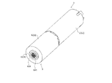
- FIG. 1 is a side view of an actuator according to Embodiment 1 of the present invention.
- FIG. 2 is a perspective view of an actuator.
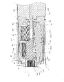
- FIG. 3 is a cross-sectional view taken along line XX of FIG.
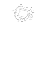
- FIG. 4 is a perspective view of a support member.
- FIG. 5 is a cross-sectional view of an actuator according to Embodiment 2 of the present invention.
- FIG. 1 is a side view of an actuator 1 according to Embodiment 1 of the present invention.
- FIG. 2 is a side view of the actuator 1.
- FIG. 3 is a cross-sectional view of the actuator 1.
- FIG. 4 is a perspective view of the support member 65.
- the planetary gear device 3 and the actuator 1 according to this embodiment are examples of the planetary gear device and the actuator 1 according to the present invention, and the present invention is not limited by the embodiments described later.
- the horizontal direction in FIGS. 1 and 3 will be referred to as the axial direction. 1 and 3 is referred to as one side in the axial direction, and the left direction is referred to as the other side in the axial direction.
- the axial direction means the axial direction of the actuator 1 and each member constituting the actuator 1 unless otherwise specified.
- the direction orthogonal to the axial direction is called the radial direction.
- the radial direction means the radial direction of the actuator 1 and each member constituting the actuator 1 unless otherwise specified.
- the outer side in the radial direction means the direction away from the center of the actuator 1 and the members constituting the actuator 1 in the radial direction.
- the inner side in the radial direction means a direction approaching the center of the actuator 1 and each member constituting the actuator 1 in the radial direction.
- the direction around the central axis of the actuator 1 parallel to the axial direction is called the circumferential direction.
- the circumferential direction means the circumferential direction of the actuator 1 and each member constituting the actuator 1 unless otherwise specified.
- the actuator 1 is exemplarily used as an actuator for an electric back door for automobiles or an electric curtain.
- the application of the actuator 1 is not particularly limited.
- the actuator 1 has an electric motor 2 and a planetary gear set 3 connected to the electric motor 2 .
- the electric motor 2 has a motor body 21 and a rotating shaft 22 .
- the electric motor 2 operates under the control of a control unit (not shown) to rotate the rotary shaft 22 to drive the planetary gear device 3 .
- the motor main body 21 has a support surface for supporting the planetary gear device 3 on the other end surface (the left end surface in FIGS. 1 to 3) in the axial direction.
- the motor body 21 has a plurality of (two in this embodiment) motor-side fixing holes on the support surface.
- the type of the electric motor is not particularly limited, and may be any of various conventionally known electric motors.
- the planetary gear device 3 reduces the rotation input from the electric motor 2 at a predetermined reduction ratio and transmits the reduced rotation to the output shaft 9 .
- the planetary gear device 3 has a housing 4 and a planetary gear mechanism 5 housed in the housing 4 .
- the housing 4 mainly functions to accommodate the planetary gear mechanism 5 .
- the housing 4 has a cylindrical portion 41 and a ring portion 42 .
- materials for the housing 4 include metals and synthetic resins.
- the cylindrical portion 41 accommodates the planetary gear mechanism 5 .
- the cylindrical portion 41 is fixed to the electric motor 2 via a first internal gear 63 which will be described later.
- the circular ring portion 42 is provided at the other end of the cylindrical portion 41 in the axial direction (also referred to as the first end of the cylindrical portion 41).
- the ring portion 42 has a support hole 421 in its central portion.
- a support cylinder portion 643 of the second internal gear 64 which will be described later, is inserted into the support hole 421 .
- the ring portion 42 has an annular locking groove 422 on one side surface (also referred to as the first side surface of the ring portion 42) in the axial direction.
- the locking groove 422 locks the other end in the axial direction of the first internal gear 63 (specifically, the second cylindrical portion 633 ), which will be described later.
- the planetary gear mechanism 5 is accommodated in the housing 4 , reduces the speed of rotation transmitted from the electric motor 2 , and transmits the reduced rotation to the output shaft 9 .
- the planetary gear mechanism 5 has a sun gear 61 , a plurality of (three in this embodiment) integrated planetary gears 62 , a first internal gear 63 , a second internal gear 64 , and a support member 65 .
- Such a planetary gear mechanism 5 has a first planetary gear mechanism 7 and a second planetary gear mechanism 8 in order from the electric motor 2 side.
- the first planetary gear mechanism 7 is composed of the sun gear 61 , the first internal gear 63 , and the first planetary part 621 of the integrated planetary gear 62 . Such a first planetary gear mechanism 7 reduces the rotation of the rotary shaft 22 of the electric motor 2 at a predetermined reduction ratio and transmits the reduced rotation to the second planetary gear mechanism 8 .
- the second planetary gear mechanism 8 is composed of the second planetary part 622 of the integrated planetary gear 62, the second internal gear 64, and the support member 65.
- the second planetary gear mechanism 8 decelerates the rotation transmitted from the first planetary gear mechanism 7 at a predetermined reduction ratio and transmits the reduced rotation to the output shaft 9 .
- Constituent members of the planetary gear mechanism 5 will be specifically described below.
- the sun gear 61 is a cylindrical external gear and fixed to the rotating shaft 22 of the electric motor 2 .
- the sun gear 61 has a sun tooth portion on its outer peripheral surface.
- the sun tooth portion has helical teeth obliquely cut with respect to the central axis of the sun gear 61 (the central axis common to the central axis of the rotating shaft 22 of the electric motor 2).
- the sun gear 61 is a helical gear and an external gear.
- materials for the sun gear 61 include metal and synthetic resin.
- the sun gear 61 may have teeth parallel to the central axis of the sun gear 61 . That is, the sun gear 61 may be both a spur gear and an external gear. Also, the sun gear 61 can be regarded as a constituent element of the planetary gear mechanism, and can also be regarded as a constituent element of the electric motor 2 . When the sun gear 61 is regarded as a component of the electric motor 2, the concept of the planetary gear mechanism does not include the sun gear.
- the integral planetary gears 62 are external gears and are arranged in the space between the sun gear 61 and the first internal gear 63 and the space between the support member 65 and the second internal gear 64 respectively.
- the integrated planetary gears 62 are evenly spaced in the circumferential direction.
- the integrated planetary gears 62 each have a first planetary portion 621, a second planetary portion 622, a first shaft portion 623, a second shaft portion 624, and a flange portion 625.
- Examples of the material of the integrated planetary gear 62 include metal and synthetic resin.
- the first planetary part 621 is provided on one half (right side in FIG. 3) of the integral planetary gear 62 in the axial direction (also referred to as the first half of the integral planetary gear 62).
- the first planetary parts 621 are arranged at regular intervals in the circumferential direction in the space between the sun gear 61 and a first internal gear 63 which will be described later.
- the integrated planetary gears 62 are arranged at equal intervals in the circumferential direction in the space between the sun gear 61 and the first internal gear 63, but the present invention is limited to this. is not.
- the first planetary part 621 has a first planetary tooth part on its outer peripheral surface.
- the first planetary toothing has helical teeth that are obliquely cut with respect to the central axis of the integrated planetary gear 62 . That is, each of the first planetary parts 621 is a helical gear and an external gear.
- the first planetary part 621 may have teeth parallel to the central axis of the first planetary part 621 . That is, the first planetary part 621 may be both a spur gear and an external gear.
- the first planetary tooth portion of the first planetary portion 621 meshes with the sun tooth portion of the sun gear 61 and the first internal tooth portion of the first internal gear 63 described later.
- the first planetary part 621 rotates (rotates) around its own central axis based on the rotation of the sun gear 61 . That is, each integrated planetary gear 62 rotates around its own central axis based on the meshing between the first planetary part 621 and the sun gear 61 .
- the first planetary part 621 rotates (revolves) around the sun gear 61 based on its own rotation and meshing with the first internal gear 63 . That is, each integral planetary gear 62 revolves around the sun gear 61 based on the rotation of the first planetary portion 621 and the meshing between the first planetary portion 621 and the first internal gear 63 .
- the central axis of the revolution of the first planetary part 621 coincides with the central axis of the sun gear 61 .
- the second planetary part 622 is provided on the other half (left side in FIG. 3) of the integrated planetary gear 62 in the axial direction (also referred to as the second half of the integrated planetary gear 62).
- the second planetary parts 622 are arranged at regular intervals in the circumferential direction in the space between the support member 65 and a second internal gear 64 which will be described later.
- the integrated planetary gears 62 are arranged at regular intervals in the circumferential direction, but the present invention is not limited to this.
- Each of the second planetary parts 622 has a second planetary tooth part on its outer peripheral surface.
- the second planetary tooth section has helical teeth that are obliquely cut with respect to the central axis of the integrated planetary gear 62 . That is, each of the second planetary parts 622 is a helical gear and an external gear. In the case of this embodiment, the number of teeth of the second planetary teeth is smaller than the number of teeth of the first planetary teeth.
- a second planetary tooth portion of the second planetary portion 622 meshes with a second internal tooth portion of a second internal gear 64 described later.
- each of the second planetary parts 622 may have teeth parallel to the central axis of the second planetary parts 622 . That is, the second planetary part 622 may be both a spur gear and an external gear.
- the second planetary part 622 rotates (rotates) around its own central axis together with the first planetary part 621 . Also, the second planetary part 622 rotates (revolves) around the support member 65 together with the first planetary part 621 .
- the first shaft portion 623 is provided at one end of the integrated planetary gear 62 in the axial direction (also referred to as the first end of the integrated planetary gear 62).
- the tip of the first shaft portion 623 (the right end in FIG. 3) is spherical.
- the first shaft portion 623 is inserted into a first guide groove 631b of a first internal gear 63, which will be described later.
- the tip of the first shaft portion 623 contacts the bottom of the first guide groove 631b when the integrated planetary gear 62 moves to one side in the axial direction. As a result, the movement of the integrated planetary gear 62 to one side in the axial direction is restricted.
- the second shaft portion 624 is provided at the other end of the integrated planetary gear 62 in the axial direction (also referred to as the second end of the integrated planetary gear 62).
- the tip of the second shaft portion 624 (the left end in FIG. 3) is spherical.
- the second shaft portion 624 is inserted into a second guide groove 642a of the second internal gear 64, which will be described later.
- the tip of the second shaft portion 624 contacts the bottom of the second guide groove 642a when the integrated planetary gear 62 moves to the other side in the axial direction. As a result, the movement of the integrated planetary gear 62 to the other side in the axial direction is restricted.
- the flange portion 625 is disc-shaped and provided between the first planetary portion 621 and the second planetary portion 622 in the axial direction.
- the outer peripheral surface of the flange portion 625 is in contact with a curved surface portion 651a of a support member 65, which will be described later.
- the flange portion 625 may not be provided between the first planetary portion 621 and the second planetary portion 622 if the support member 65, which will be described later, is not provided.
- Both ends (first shaft portion 623 and second shaft portion 624) in the axial direction of the integrated planetary gear 62 having the configuration described above are supported by the first internal gear 63 and the second internal gear 64.
- the integrated planetary gear 62 is rotatable (rotating) about its own central axis and rotatable (revolving) about the central axis of the planetary gear mechanism 5 .
- the planetary gear mechanism 5 does not include a carrier for supporting the integrated planetary gear 62.
- the first internal gear 63 is arranged around the first planetary part 621 and meshes with the first planetary part 621 .
- the first internal gear 63 has a connection cover 631 , a first cylindrical portion 632 and a second cylindrical portion 633 .
- Examples of materials for the first internal gear 63 include metal and synthetic resin.
- connection cover 631 is a member for attaching the planetary gear device 3 to the electric motor 2 .
- connection cover 631 is ring-shaped and has a through hole 631a in the center. A part of the motor body 21 of the electric motor 2 is fitted in the through hole 631a. The rotary shaft 22 of the electric motor 2 and the sun gear 61 are arranged inside the through hole 631a.
- connection cover 631 fixes the housing 4 to the electric motor 2 .
- connection lid 631 has a first guide groove 631b on the side surface on the other side in the axial direction (also referred to as the first side surface of the connection lid 631).
- the first guide groove 631b has an annular shape centered on the central axis of the first internal gear 63 .
- the groove width of the first guide groove 631b is slightly larger than the diameter of the first shaft portion 623 of the integrated planetary gear 62.
- the first shaft portion 623 of the integrated planetary gear 62 is inserted into the first guide groove 631b.
- Such a first guide groove 631b is for guiding the rotation (rotation and revolution) of the integrated planetary gear 62. As shown in FIG.
- connection cover 631 supports the first end of the integrated planetary gear 62 in a rotatable state. That is, the first internal gear 63 supports the first end of the integral planetary gear 62 .
- the first cylindrical portion 632 is cylindrical. One end of the first cylindrical portion 632 in the axial direction (also referred to as the first end of the first cylindrical portion 632 ) is connected to the connection lid body 631 .
- the first cylindrical portion 632 has a first internal tooth portion on its inner peripheral surface.
- the first internal tooth portion has helical teeth obliquely cut with respect to the central axis of the first cylindrical portion 632 (the central axis common to the central axis of the rotating shaft 22 of the electric motor 2).
- Such a first tubular portion 632 is a helical gear and an internal gear.
- the first cylindrical portion 632 is arranged around the first planetary portion 621 in the housing space of the housing 4 .
- the first inner toothed portion of the first cylinder portion 632 meshes with the first planetary toothed portion of the first planetary portion 621 .
- the first internal tooth portion of the first cylindrical portion 632 may have teeth parallel to the central axis of the first cylindrical portion 632 . That is, the first tubular portion 632 may be both a spur gear and an external gear.
- the second cylindrical portion 633 is cylindrical. One end of the second tubular portion 633 in the axial direction (also referred to as the first end of the second tubular portion 633 ) is connected to the first tubular portion 632 . The other end of the second tubular portion 633 in the axial direction (also referred to as the second end of the second tubular portion 633 ) is engaged with the engaging groove 422 of the ring portion 42 of the housing 4 .
- the second cylindrical portion 633 is arranged so as to surround the second planetary gear mechanism 8 (the second internal gear 64). Such a second tubular portion 633 can suppress leakage of sound and vibration generated from the second planetary gear mechanism 8 to the outside. In addition, since the first end of the second tubular portion 633 is connected to the first tubular portion 632 , the axial centers of the first internal gear and the second internal gear can be aligned via the housing 41 .
- the first internal gear 63 is fixed to the housing 4 at both ends in the axial direction. Therefore, the first internal gear 63 does not rotate with respect to the housing 4 .
- the second internal gear 64 is arranged around the second planetary portion 622 and meshes with the second planetary portion 622 .
- the second internal gear 64 has a tubular portion 641 , an annular ring portion 642 and a supporting tubular portion 643 .
- Examples of materials for the second internal gear 64 include metal and synthetic resin.
- the cylindrical portion 641 has a cylindrical shape and accommodates the second planetary portion 622 inside. Further, the cylindrical portion 641 is arranged inside the second cylindrical portion 633 of the first internal gear 63 . A radial gap exists between the outer peripheral surface of the tubular portion 641 and the inner peripheral surface of the second tubular portion 633 .
- the tubular portion 641 has a second internal tooth portion having a plurality of axially extending tooth portions on the inner peripheral surface.
- the second internal tooth portion has helical teeth obliquely cut with respect to the central axis of the cylindrical portion 641 (the central axis common to the central axis of the rotating shaft 22 of the electric motor 2).
- Such cylindrical portion 641 is a helical gear and an internal gear.
- the second inner toothed portion of the tubular portion 641 meshes with the second planetary toothed portion of the second planetary portion 622 .
- the second internal tooth portion of the tubular portion 641 may have teeth parallel to the central axis of the tubular portion 641 . That is, the cylindrical portion 641 may be both a spur gear and an external gear.
- the circular ring portion 642 is ring-shaped and is connected to the other end portion of the cylindrical portion 641 in the axial direction (also referred to as the first end portion of the cylindrical portion 641). Specifically, the radially outer end of the ring portion 642 is connected to the first end of the cylindrical portion 641 .
- the circular ring portion 642 has a second guide groove 642a on one side surface in the axial direction (also referred to as the first side surface of the circular ring portion 642).
- the second guide groove 642a has an annular shape centered on the central axis of the second internal gear 64 .
- the second guide groove 642a faces the first guide groove 631b in the axial direction.
- the groove width of the second guide groove 642 a is slightly larger than the diameter of the second shaft portion 624 of the integrated planetary gear 62 .
- the second shaft portion 624 is inserted into the second guide groove 642a.
- Such a second guide groove 642a is for guiding the rotation (rotation and revolution) of the integrated planetary gear 62. As shown in FIG.
- the ring portion 642 supports the second end portion of the integrated planetary gear 62 in a rotatable state.
- the second internal gear 64 supports the second end of the integral planetary gear 62 .
- the support tubular portion 643 is a tubular member for supporting the second internal gear 64 with respect to the housing 4 . Moreover, the support cylinder portion 643 is also a member for supporting the output shaft 9 and the support member 65 .
- the support cylinder part 643 has a disk-shaped cover part 643a at one end in the axial direction.
- the support cylinder portion 643 is connected to the inner end portion in the radial direction of the ring portion 642 .
- the support cylinder portion 643 extends from the inner end portion of the ring portion 642 in the radial direction to both sides in the axial direction.
- the other axial end of the support cylinder portion 643 is rotatably inserted into the support hole 421 of the circular ring portion 42 of the housing 4 .
- the second internal gear 64 is thus rotatable with respect to the housing 4 .
- the support cylinder portion 643 has an engagement shape with the output shaft 9 on the inner peripheral surface.
- the output shaft 9 is inserted into the support cylinder portion 643 .
- the support cylinder part 643 and the output shaft 9 are engaged by the engagement shape. Therefore, the support cylinder portion 643 and the output shaft 9 rotate together.
- Engagement shapes include, for example, splines, D holes, and/or oval holes.
- the support cylinder portion 643 may have a shape that reduces the contact area with the inner surface of the support hole 421 of the housing 4 on the outer peripheral surface.
- An example of this shape is a wave shape that repeats unevenness in the circumferential direction. Since the contact area between the outer peripheral surface of the support cylinder portion 643 and the inner surface of the support hole 421 of the housing 4 is reduced, the resistance due to sliding therebetween can be reduced, and the efficiency of the planetary gear device 3 can be improved.
- the support cylinder portion 643 has a recess 643b on one side surface of the lid portion 643a in the axial direction.
- a second projection 652b of a support member 65 which will be described later, is inserted into the recess 643b. That is, the second internal gear 64 supports the support member 65 .
- the support member 65 is a member for supporting the second planetary part 622 of the integrated planetary gear 62 from inside. Such a support member 65 is a member for positioning the integrated planetary gear 62 and suppressing inclination of the integrated planetary gear 62 in use.
- the support member 65 has a body portion 651 and a flange portion 652 .
- Examples of materials for the support member 65 include metal and synthetic resin.
- the body portion 651 extends in the axial direction.
- the body portion 651 has curved surface portions 651 a curved along the outer peripheral surface of the second planetary portion 622 at three locations in the circumferential direction.
- Each curved surface portion 651a faces the outer peripheral surface of the second planetary portion 622 with a gap therebetween.
- the curved surface portions 651 a are in contact with the outer peripheral surface of the flange portion 625 of the integrated planetary gear 62 .
- the body portion 651 has a first convex portion 651b on one end face in the axial direction (also referred to as a first end portion of the body portion 651).
- the first convex portion 651b is inserted into the sun gear 61 . Therefore, one end of the support member 65 in the axial direction (also referred to as the first end of the support member 65 ) is supported by the sun gear 61 .
- the flange portion 652 is disc-shaped.
- the flange portion 652 is connected to the other end portion of the body portion 651 in the axial direction (also referred to as the second end portion of the body portion 651).
- the outer diameter of the flange portion 652 is larger than the outer diameter of the body portion 651 .
- the flange portion 652 has notches 652a at three places in the circumferential direction of the outer peripheral surface.
- Each of the notch portions 652 a has a shape along the outer peripheral surface of the second shaft portion 624 of the integrated planetary gear 62 .
- the notch portion 652a holds the outer peripheral surface of the second shaft portion 624 from the inner side in the radial direction and both sides in the circumferential direction.
- the flange portion 652 has a second convex portion 652b on the side surface on the other side in the axial direction (also referred to as the first side surface of the flange portion 652).
- the second convex portion 652 b is inserted into the concave portion 643 b of the support cylinder portion 643 of the second internal gear 64 . Therefore, the other end of the support member 65 in the axial direction (also referred to as the second end of the support member 65 ) is supported by the second internal gear 64 .
- the support member 65 is rotatably supported by the sun gear 61 and the second internal gear 64. Further, the support member 65 supports the integrated planetary gear 62 with the curved surface portion 651a and the notch portion 652a. Such a support member 65 rotates as the integrated planetary gear 62 revolves during use. At this time, the support member 65 suppresses inclination of the integrated planetary gear 62 . Incidentally, the support member 65 may be omitted.
- the first direction regarding the rotation direction of each member means the clockwise direction when each member is viewed from one side (the right side in FIGS. 1 to 3) in the axial direction.
- the second direction regarding the rotation direction of each member means the direction opposite to the clockwise direction when each member is viewed from one side in the axial direction (the right side in FIGS. 1 to 3). do.
- the sun gear 61 rotates together with the rotating shaft 22 in the first direction.
- the integrated planetary gear 62 (first planetary portion 621) rotates (rotates) in the second direction around its own central axis.
- the integrated planetary gear 62 (first planetary portion 621) rotates around the rotation center of the sun gear 61 based on the rotation of the first planetary portion 621 and the engagement between the first planetary portion 621 and the first internal gear 63. Rotate (revolve) about an axis in a first direction.
- an axial load (thrust load) is applied to the first planetary portion 621 according to the inclination direction of the first planetary tooth portion.
- a thrust load causes the integrated planetary gear 62 (first planetary portion 621) to move in the axial direction.
- the integral planetary gear 62 (first planetary portion 621) moves to one side (right side in FIGS. 1 to 3) in the axial direction based on the thrust load
- the tip of the first shaft portion 623 and the tip of the second shaft portion 624 are spherical. Therefore, the contact between the tip of the first shaft portion 623 and the tip of the second shaft portion 624 and the bottom of the first guide groove 631b and the bottom of the second guide groove 642a becomes point contact, and the sliding friction at the contact portion becomes point contact. becomes smaller.
- the integrated planetary gear 62 rotates and revolves while being guided by the first guide groove 631b and the second guide groove 642a.
- the first shaft portion 623 and the second shaft portion 624 of the integrated planetary gear 62 are in rolling contact with the inner surfaces of the first guide groove 631b and the second guide groove 642a.
- the sliding resistance during use can be reduced as compared with an actuator provided with a carrier as in the conventional structure.
- the second planetary part 622 When the integrated planetary gear 62 (first planetary part 621) rotates and revolves, the second planetary part 622 also rotates and revolves together with the first planetary part 621. Then, the second internal gear 64 rotates in the first direction as the second planetary portion 622 rotates. Then, the rotation of the second internal gear 64 is transmitted to the output shaft 9 .
- FIG. 5 is a cross-sectional view of an actuator 1B according to Embodiment 2 of the present invention.
- the structure of the support member 65B of the planetary gear device 3B is different from the structure of the support member 65 of the actuator 1 according to the first embodiment.
- Other structures are the same as those of the actuator 1 according to the first embodiment.
- the structure of the support member 65B will be described below. Note that the description of the first embodiment may be used as appropriate for the configuration other than the support member 65B.
- the support member 65B is a shaft-shaped external gear and has support-side teeth on its outer peripheral surface.
- the support-side tooth portion has helical teeth obliquely cut with respect to the central axis of the support member 65B (the central axis common to the central axis of the rotating shaft 22 of the electric motor 2).
- the support member 65B is a helical gear and an external gear.
- materials for the support member 65B include metal and synthetic resin.
- the material of the support member 65B is preferably a synthetic resin whose elastic modulus is lower than that of the material of the second planetary portion 622 . If the material of the support member 65B is a synthetic resin having a low elastic modulus, the teeth of the support member 65B can mesh while being crushed, so that backlash can be suppressed.
- the support member 65B may have teeth parallel to the central axis of the second cylindrical portion 633 . That is, the support member 65B may be both a spur gear and an external gear.
- the support member 65B has a first projection 651c at one end in the axial direction.
- the first protrusion 651 c is inserted into the sun gear 61 . Therefore, one end of the support member 65B in the axial direction (also referred to as the first end of the support member 65B) is supported by the sun gear 61 .
- the support member 65B has a second protrusion 652c at the other end in the axial direction.
- the second convex portion 652 c is inserted into the concave portion 643 b of the support cylinder portion 643 of the second internal gear 64 . Therefore, the other end of the support member 65B in the axial direction (also referred to as the second end of the support member 65B) is supported by the second internal gear 64 .
- the support member 65B is rotatably supported by the sun gear 61 and the second internal gear 64. Further, the support-side tooth portion of the support member 65B meshes with the second planetary tooth portion of the second planetary portion 622 with zero backlash.
- the support member 65B rotates as the integrated planetary gear 62 rotates. At this time, the support member 65B supports the integrated planetary gear 62 so as to position the integrated planetary gear 62 and suppress the inclination of the integrated planetary gear 62 .
- the support-side tooth portion of the support member 65B and the second planetary tooth portion of the second planetary portion 622 mesh with each other with zero backlash. Therefore, the support member 65B can position the integrated planetary gear 62 more reliably than the support member 65B according to the first embodiment described above.
- Other configurations and functions/effects are the same as those of the first embodiment described above.
- the synthetic resin includes, for example, ryallate (PAAR), polyacetal (POM), polyamide (PA), polycarbonate (PC), polybutylene terephthalate (PBT). ), polyethersulfone (PES), polyetheretherketone (PEEK), and the like.
- PAAR ryallate
- POM polyacetal
- PA polyamide
- PC polycarbonate
- PBT polybutylene terephthalate
- PES polyethersulfone
- PEEK polyetheretherketone
- the planetary gear device and the actuator according to the present invention do not need to include all the members that the planetary gear device 3 and the actuator 1 according to the above-described embodiment have.
- the planetary gear device and the actuator according to the present invention may be composed of one or a plurality of members arbitrarily extracted from the planetary gear device 3 and the actuator 1 according to the above-described embodiments within a technically consistent range.
- the planetary gear device and actuator according to the present invention can be incorporated into various mechanical devices.
Landscapes
- Engineering & Computer Science (AREA)
- General Engineering & Computer Science (AREA)
- Mechanical Engineering (AREA)
- Retarders (AREA)
Abstract
遊星歯車機構は、モータの回転を減速して出力軸に伝える遊星歯車装置であって、外周面に遊星歯部を有する複数の遊星歯車と、複数の遊星歯車を囲むように設けられ、内周面に遊星歯部と噛み合う第一内歯部を有する第一内歯車と、複数の遊星歯車を囲むように第一内歯車よりも出力軸側に設けられ、内周面に遊星歯部と噛み合う第二内歯部を有する第二内歯車と、を備え、遊星歯車の軸方向における両端部は、第一内歯車及び第二内歯車に回転可能に支持されている。
Description
本発明は、遊星歯車装置及びアクチュエータに関する。
遊星歯車装置は、入力された回転を減速して出力する減速機として、自動車及びロボット等の様々な機械装置に用いられている(特許文献1参照)。
特許文献1には、モータの回転を減速して出力軸に伝達する遊星歯車装置が開示されている。このような遊星歯車装置は、太陽歯車や内歯車、キャリア等の構成部材を収容するハウジングを有する。
ハウジングは、円輪状の取付部を有する。取付部は、例えば、ボルト等の締結部品により、モータに固定される。
特許文献1に開示された遊星歯車装置の場合、使用時において、キャリアの側面とハウジングの内側面とが摺接し、キャリアと遊星軸孔も摺動するため、これらの摺動抵抗が大きく、遊星歯車装置の効率が低下する可能性がある。
本発明の目的は、使用時の摺動抵抗を小さくして、遊星歯車装置の効率を向上できる遊星歯車装置及びアクチュエータを提供することである。
本発明に係る遊星歯車装置の一態様は、
モータの回転を減速して出力軸に伝える遊星歯車装置であって、
外周面に遊星歯部を有する複数の遊星歯車と、
複数の遊星歯車を囲むように設けられ、内周面に遊星歯部と噛み合う第一内歯部を有する第一内歯車と、
複数の遊星歯車を囲むように第一内歯車よりも出力軸側に設けられ、内周面に遊星歯部と噛み合う第二内歯部を有する第二内歯車と、を備え、
遊星歯車の軸方向における両端部は、第一内歯車及び第二内歯車に回転可能に支持されている。
モータの回転を減速して出力軸に伝える遊星歯車装置であって、
外周面に遊星歯部を有する複数の遊星歯車と、
複数の遊星歯車を囲むように設けられ、内周面に遊星歯部と噛み合う第一内歯部を有する第一内歯車と、
複数の遊星歯車を囲むように第一内歯車よりも出力軸側に設けられ、内周面に遊星歯部と噛み合う第二内歯部を有する第二内歯車と、を備え、
遊星歯車の軸方向における両端部は、第一内歯車及び第二内歯車に回転可能に支持されている。
本発明に係るアクチュエータの一態様は、
上記構成の遊星歯車装置と、
遊星歯車装置に接続され遊星歯車装置を駆動するモータと、
を備える。
上記構成の遊星歯車装置と、
遊星歯車装置に接続され遊星歯車装置を駆動するモータと、
を備える。
本発明によれば、使用時の摺動抵抗を小さくして、遊星歯車装置の効率を向上できる遊星歯車装置及びアクチュエータを提供できる。
以下、本発明のいくつかの実施形態について図面に基づいて詳細に説明する。
[実施形態1]
図1は、本発明の実施形態1に係るアクチュエータ1の側面図である。図2は、アクチュエータ1の側面図である。図3は、アクチュエータ1の断面図である。図4は、サポート部材65の斜視図である。
図1は、本発明の実施形態1に係るアクチュエータ1の側面図である。図2は、アクチュエータ1の側面図である。図3は、アクチュエータ1の断面図である。図4は、サポート部材65の斜視図である。
本実施形態に係る遊星歯車装置3及びアクチュエータ1は、本発明に係る遊星歯車装置及びアクチュエータの一例であり、本発明は後述の実施形態により限定されない。
以下の説明では、図1及び図3における左右方向を軸方向という。又、図1及び図3における右方向を軸方向における一方側といい、左方向を軸方向における他方側という。軸方向とは、特に断らない限り、アクチュエータ1及びアクチュエータ1を構成する各部材の軸方向を意味する。
又、図1~図3において軸方向に直交する方向を径方向という。径方向とは、特に断らない限り、アクチュエータ1及びアクチュエータ1を構成する各部材の径方向を意味する。径方向における外側とは、径方向において、アクチュエータ1及びアクチュエータ1を構成する各部材の中心から離れる方向を意味する。一方、径方向における内側とは、径方向において、アクチュエータ1及びアクチュエータ1を構成する各部材の中心に近づく方向を意味する。
又、図1~図3において、軸方向に平行なアクチュエータ1の中心軸回りの方向を周方向という。周方向とは、特に断らない限り、アクチュエータ1及びアクチュエータ1を構成する各部材の周方向を意味する。
以下、図1~図4を参照して、本実施形態に係るアクチュエータ1について説明する。
<アクチュエータ>
アクチュエータ1は、例示的に、自動車用の電動バックドアや電動式のカーテンのアクチュエータとして使用される。但し、アクチュエータ1の用途は、特に限定されるものではない。
アクチュエータ1は、例示的に、自動車用の電動バックドアや電動式のカーテンのアクチュエータとして使用される。但し、アクチュエータ1の用途は、特に限定されるものではない。
アクチュエータ1は、電動モータ2と、電動モータ2に接続された遊星歯車装置3と、を有する。
<電動モータ>
電動モータ2は、モータ本体21と、回転軸22と、を有する。電動モータ2は、制御部(不図示)の制御下で作動し、回転軸22を回転させて遊星歯車装置3を駆動する。
電動モータ2は、モータ本体21と、回転軸22と、を有する。電動モータ2は、制御部(不図示)の制御下で作動し、回転軸22を回転させて遊星歯車装置3を駆動する。
モータ本体21は、軸方向における他方側の端面(図1~図3における左端面)に、遊星歯車装置3を支持するための支持面を有する。モータ本体21は、支持面に、複数(本実施形態の場合、2個)のモータ側固定孔を有する。尚、電動モータの種類は、特に限定されず、従来から知られている種々の電動モータであってよい。
<遊星歯車装置>
遊星歯車装置3は、電動モータ2から入力された回転を、所定の減速比で減速して出力軸9に伝達する。遊星歯車装置3は、ハウジング4と、ハウジング4に収容された遊星歯車機構5と、を有する。
遊星歯車装置3は、電動モータ2から入力された回転を、所定の減速比で減速して出力軸9に伝達する。遊星歯車装置3は、ハウジング4と、ハウジング4に収容された遊星歯車機構5と、を有する。
<ハウジング>
ハウジング4は、主に、遊星歯車機構5を収容する機能を有する。具体的には、ハウジング4は、円筒部41と、円輪部42と、を有する。ハウジング4の材料として、例示的に、金属又は合成樹脂が挙げられる。
ハウジング4は、主に、遊星歯車機構5を収容する機能を有する。具体的には、ハウジング4は、円筒部41と、円輪部42と、を有する。ハウジング4の材料として、例示的に、金属又は合成樹脂が挙げられる。
(円筒部)
円筒部41は、遊星歯車機構5を収容している。円筒部41は、後述の第一内歯車63を介して、電動モータ2に固定されている。
円筒部41は、遊星歯車機構5を収容している。円筒部41は、後述の第一内歯車63を介して、電動モータ2に固定されている。
(円輪部)
円輪部42は、円筒部41の軸方向における他方側の端部(円筒部41の第一端部とも称する。)に設けられている。円輪部42は、中央部に支持孔421を有する。支持孔421には、後述の第二内歯車64の支持筒部643が挿入されている。
円輪部42は、円筒部41の軸方向における他方側の端部(円筒部41の第一端部とも称する。)に設けられている。円輪部42は、中央部に支持孔421を有する。支持孔421には、後述の第二内歯車64の支持筒部643が挿入されている。
円輪部42は、軸方向における一方側の側面(円輪部42の第一側面とも称する。)に、円環状の係止溝422を有する。係止溝422には、後述の第一内歯車63(具体的には、第二筒部633)の軸方向における他方側の端部が係止されている。
<遊星歯車機構>
遊星歯車機構5は、ハウジング4に収容され、電動モータ2から伝達された回転を減速して出力軸9に伝達する。
遊星歯車機構5は、ハウジング4に収容され、電動モータ2から伝達された回転を減速して出力軸9に伝達する。
遊星歯車機構5は、太陽歯車61、複数(本実施形態の場合、3個)の一体型遊星歯車62、第一内歯車63、第二内歯車64、及びサポート部材65を有する。
このような遊星歯車機構5は、電動モータ2側から順に、第一遊星歯車機構7及び第二遊星歯車機構8を有する。
第一遊星歯車機構7は、太陽歯車61、第一内歯車63、及び一体型遊星歯車62における第一遊星部621により構成されている。このような第一遊星歯車機構7は、電動モータ2の回転軸22の回転を、所定の減速比で減速して、第二遊星歯車機構8に伝達する。
第二遊星歯車機構8は、一体型遊星歯車62における第二遊星部622、第二内歯車64、及びサポート部材65により構成されている。第二遊星歯車機構8は、第一遊星歯車機構7から伝達された回転を、所定の減速比で減速して、出力軸9に伝達する。以下、遊星歯車機構5の構成部材について具体的に説明する。
(太陽歯車)
太陽歯車61は、筒状の外歯車であって、電動モータ2の回転軸22に固定されている。具体的には、太陽歯車61は、外周面に、太陽歯部を有する。太陽歯部は、太陽歯車61の中心軸(電動モータ2の回転軸22の中心軸と共通の中心軸)に対して斜めに切られた螺旋状の歯を有する。
太陽歯車61は、筒状の外歯車であって、電動モータ2の回転軸22に固定されている。具体的には、太陽歯車61は、外周面に、太陽歯部を有する。太陽歯部は、太陽歯車61の中心軸(電動モータ2の回転軸22の中心軸と共通の中心軸)に対して斜めに切られた螺旋状の歯を有する。
つまり、太陽歯車61は、はすば歯車であり且つ外歯車である。太陽歯車61の材料として、例示的に、金属又は合成樹脂が挙げられる。
尚、太陽歯車61は、太陽歯車61の中心軸に平行な歯を有してもよい。つまり、太陽歯車61は、平歯車であり且つ外歯車であってもよい。又、太陽歯車61は、遊星歯車機構の構成要素として捉えることもできるし、電動モータ2の構成要素として捉えることもできる。太陽歯車61を電動モータ2の構成要素として捉えた場合、遊星歯車機構の概念には、太陽歯車は含まれない。
(一体型遊星歯車)
一体型遊星歯車62はそれぞれ、外歯車であって、太陽歯車61と第一内歯車63との間の空間及びサポート部材65と第二内歯車64との間の空間に配置されている。一体型遊星歯車62は、周方向において等間隔に配置されている。
一体型遊星歯車62はそれぞれ、外歯車であって、太陽歯車61と第一内歯車63との間の空間及びサポート部材65と第二内歯車64との間の空間に配置されている。一体型遊星歯車62は、周方向において等間隔に配置されている。
一体型遊星歯車62はそれぞれ、第一遊星部621、第二遊星部622、第一軸部623、第二軸部624、及びフランジ部625を有する。一体型遊星歯車62の材料として、例示的に、金属又は合成樹脂が挙げられる。
(第一遊星部)
第一遊星部621は、一体型遊星歯車62の軸方向における一方側(図3における右側)の半部(一体型遊星歯車62の第一半部とも称する。)に設けられている。第一遊星部621は、太陽歯車61と後述の第一内歯車63との間の空間において円周方向に等間隔に配置されている。尚、本実施形態では一体型遊星歯車62は、太陽歯車61と第一内歯車63との間の空間において円周方向に等間隔に配置されているが、本発明はこれに限定されるものではない。
第一遊星部621は、一体型遊星歯車62の軸方向における一方側(図3における右側)の半部(一体型遊星歯車62の第一半部とも称する。)に設けられている。第一遊星部621は、太陽歯車61と後述の第一内歯車63との間の空間において円周方向に等間隔に配置されている。尚、本実施形態では一体型遊星歯車62は、太陽歯車61と第一内歯車63との間の空間において円周方向に等間隔に配置されているが、本発明はこれに限定されるものではない。
第一遊星部621は、外周面に、第一遊星歯部を有する。第一遊星歯部は、一体型遊星歯車62の中心軸に対して斜めに切られた螺旋状の歯を有する。つまり、第一遊星部621はそれぞれ、はすば歯車であり且つ外歯車である。
尚、第一遊星部621は、第一遊星部621の中心軸に平行な歯を有してもよい。つまり、第一遊星部621は、平歯車であり且つ外歯車であってもよい。
第一遊星部621の第一遊星歯部は、太陽歯車61の太陽歯部及び後述の第一内歯車63の第一内歯部と噛合している。
第一遊星部621は、太陽歯車61の回転に基づいて、自身の中心軸を中心に回転(自転)する。つまり、一体型遊星歯車62はそれぞれ、第一遊星部621と太陽歯車61との歯合に基づいて、自身の中心軸を中心に回転する。
又、第一遊星部621は、自身の回転及び第一内歯車63との噛合に基づいて、太陽歯車61の周りを回転(公転)する。つまり、一体型遊星歯車62はそれぞれ、第一遊星部621の自転及び第一遊星部621と第一内歯車63との歯合に基づいて、太陽歯車61の周りを公転する。尚、第一遊星部621の公転の中心軸は、太陽歯車61の中心軸に一致する。
(第二遊星部)
第二遊星部622は、一体型遊星歯車62の軸方向における他方側(図3における左側)の半部(一体型遊星歯車62の第二半部とも称する。)に設けられている。第二遊星部622は、サポート部材65と後述の第二内歯車64との間の空間において円周方向に等間隔に配置されている。尚、本実施形態では一体型遊星歯車62は、円周方向に等間隔に配置されているが、本発明はこれに限定されるものではない。
第二遊星部622は、一体型遊星歯車62の軸方向における他方側(図3における左側)の半部(一体型遊星歯車62の第二半部とも称する。)に設けられている。第二遊星部622は、サポート部材65と後述の第二内歯車64との間の空間において円周方向に等間隔に配置されている。尚、本実施形態では一体型遊星歯車62は、円周方向に等間隔に配置されているが、本発明はこれに限定されるものではない。
第二遊星部622はそれぞれ、外周面に、第二遊星歯部を有する。第二遊星歯部は、一体型遊星歯車62の中心軸に対して斜めに切られた螺旋状の歯を有する。つまり、第二遊星部622はそれぞれ、はすば歯車であり且つ外歯車である。本実施形態の場合、第二遊星歯部の歯数は、第一遊星歯部の歯数よりも少ない。第二遊星部622の第二遊星歯部は、後述の第二内歯車64の第二内歯部と噛合している。
尚、第二遊星部622はそれぞれ、第二遊星部622の中心軸に平行な歯を有してもよい。つまり、第二遊星部622は、平歯車であり且つ外歯車であってもよい。
第二遊星部622は、第一遊星部621と共に、自身の中心軸を中心に回転(自転)する。又、第二遊星部622は、第一遊星部621と共に、サポート部材65の周りを回転(公転)する。
(第一軸部)
第一軸部623は、一体型遊星歯車62の軸方向における一方側の端部(一体型遊星歯車62の第一端部とも称する。)に設けられている。第一軸部623の先端部(図3における右端部)は、球面状である。第一軸部623は、後述の第一内歯車63の第一ガイド溝631bに挿入されている。
第一軸部623は、一体型遊星歯車62の軸方向における一方側の端部(一体型遊星歯車62の第一端部とも称する。)に設けられている。第一軸部623の先端部(図3における右端部)は、球面状である。第一軸部623は、後述の第一内歯車63の第一ガイド溝631bに挿入されている。
第一軸部623の先端部は、一体型遊星歯車62が軸方向における一方側に移動した場合に、第一ガイド溝631bの底部と当接する。この結果、一体型遊星歯車62の軸方向における一方側への移動が規制される。
(第二軸部)
第二軸部624は、一体型遊星歯車62の軸方向における他方側の端部(一体型遊星歯車62の第二端部とも称する。)に設けられている。第二軸部624の先端部(図3における左端部)は、球面状である。第二軸部624は、後述の第二内歯車64の第二ガイド溝642aに挿入されている。
第二軸部624は、一体型遊星歯車62の軸方向における他方側の端部(一体型遊星歯車62の第二端部とも称する。)に設けられている。第二軸部624の先端部(図3における左端部)は、球面状である。第二軸部624は、後述の第二内歯車64の第二ガイド溝642aに挿入されている。
第二軸部624の先端部は、一体型遊星歯車62が軸方向における他方側に移動した場合に、第二ガイド溝642aの底部と当接する。この結果、一体型遊星歯車62の軸方向における他方側への移動が規制される。
(フランジ部)
フランジ部625は、円板状であって、軸方向における第一遊星部621と第二遊星部622との間に設けられている。フランジ部625の外周面は、後述のサポート部材65の曲面部651aに当接している。尚、後述のサポート部材65を設けない場合、第一遊星部621と第二遊星部622との間にフランジ部625を設けなくてもよい。
フランジ部625は、円板状であって、軸方向における第一遊星部621と第二遊星部622との間に設けられている。フランジ部625の外周面は、後述のサポート部材65の曲面部651aに当接している。尚、後述のサポート部材65を設けない場合、第一遊星部621と第二遊星部622との間にフランジ部625を設けなくてもよい。
以上のような構成を有する一体型遊星歯車62はそれぞれ、軸方向における両端部(第一軸部623及び第二軸部624)が、第一内歯車63及び第二内歯車64に支持されている。この状態で、一体型遊星歯車62は、自身の中心軸を中心に回転可能(自転可能)であり、且つ、遊星歯車機構5の中心軸を中心に回転可能(公転可能)である。
以上のように、本実施形態に係る遊星歯車機構5は、一体型遊星歯車62を支持するためのキャリアを備えていない。
<第一内歯車>
第一内歯車63は、第一遊星部621の周囲に配置され、第一遊星部621と噛合している。
第一内歯車63は、第一遊星部621の周囲に配置され、第一遊星部621と噛合している。
第一内歯車63は、接続蓋体631、第一筒部632、及び第二筒部633を有する。第一内歯車63の材料として、例示的に、金属又は合成樹脂が挙げられる。
(接続蓋体)
接続蓋体631は、遊星歯車装置3を電動モータ2に取り付けるための部材である。
接続蓋体631は、遊星歯車装置3を電動モータ2に取り付けるための部材である。
接続蓋体631は、円輪状であって、中心部に貫通孔631aを有する。貫通孔631aには、電動モータ2におけるモータ本体21の一部が内嵌されている。貫通孔631aの内側には、電動モータ2の回転軸22及び太陽歯車61が配置されている。
接続蓋体631の軸方向における一方側の側面は、電動モータ2に固定されている。又、接続蓋体631の外周面には、ハウジング4の円筒部41が固定されている。つまり、接続蓋体631は、ハウジング4を電動モータ2に固定している。
接続蓋体631は、軸方向における他方側の側面(接続蓋体631の第一側面とも称する。)に、第一ガイド溝631bを有する。第一ガイド溝631bは、第一内歯車63の中心軸を中心とした円環状である。
第一ガイド溝631bの溝幅は、一体型遊星歯車62の第一軸部623の直径よりも僅かに大きい。第一ガイド溝631bには、一体型遊星歯車62の第一軸部623が挿入されている。このような第一ガイド溝631bは、一体型遊星歯車62の回転(自転及び公転)をガイドするためのものである。
以上のように、接続蓋体631は、一体型遊星歯車62の第一端部を回転可能な状態で支持している。つまり、第一内歯車63は、一体型遊星歯車62の第一端部を支持している。
(第一筒部)
第一筒部632は、円筒状である。第一筒部632の軸方向における一方側の端部(第一筒部632の第一端部とも称する。)は、接続蓋体631に接続されている。
第一筒部632は、円筒状である。第一筒部632の軸方向における一方側の端部(第一筒部632の第一端部とも称する。)は、接続蓋体631に接続されている。
第一筒部632は、内周面に、第一内歯部を有する。第一内歯部は、第一筒部632の中心軸(電動モータ2の回転軸22の中心軸と共通の中心軸)に対して斜めに切られた螺旋状の歯を有する。このような第一筒部632は、はすば歯車であり且つ内歯車である。
第一筒部632は、ハウジング4の収容空間において、第一遊星部621の周囲に配置されている。この状態で、第一筒部632の第一内歯部は、第一遊星部621の第一遊星歯部と噛合している。尚、第一筒部632の第一内歯部は、第一筒部632の中心軸に平行な歯を有してもよい。つまり、第一筒部632は、平歯車であり且つ外歯車であってもよい。
(第二筒部)
第二筒部633は、円筒状である。第二筒部633の軸方向における一方側の端部(第二筒部633の第一端部とも称する。)は、第一筒部632に接続されている。第二筒部633の軸方向における他方側の端部(第二筒部633の第二端部とも称する。)は、ハウジング4における円輪部42の係止溝422に係止されている。
第二筒部633は、円筒状である。第二筒部633の軸方向における一方側の端部(第二筒部633の第一端部とも称する。)は、第一筒部632に接続されている。第二筒部633の軸方向における他方側の端部(第二筒部633の第二端部とも称する。)は、ハウジング4における円輪部42の係止溝422に係止されている。
第二筒部633は、第二遊星歯車機構8(第二内歯車64)を囲むように配置されている。このような第二筒部633は、第二遊星歯車機構8から発生する音や振動が外部に漏れ出ることを抑制できる。又、第二筒部633の第一端部が、第一筒部632に接続されていることで、ハウジング41を介して第一内歯車及び第二内歯車の軸心を揃えることができる。
以上のように、第一内歯車63は、軸方向の両端部において、ハウジング4に固定されている。よって、第一内歯車63は、ハウジング4に対して回転しない。
<第二内歯車>
第二内歯車64は、第二遊星部622の周囲に配置され、第二遊星部622と噛合している。第二内歯車64は、筒部641、円輪部642、及び支持筒部643を有する。第二内歯車64の材料として、例示的に、金属又は合成樹脂が挙げられる。
第二内歯車64は、第二遊星部622の周囲に配置され、第二遊星部622と噛合している。第二内歯車64は、筒部641、円輪部642、及び支持筒部643を有する。第二内歯車64の材料として、例示的に、金属又は合成樹脂が挙げられる。
(筒部)
筒部641は、円筒状であって、内側に、第二遊星部622を収容している。又、筒部641は、第一内歯車63における第二筒部633の内側に配置されている。筒部641の外周面と第二筒部633の内周面との間には、径方向における隙間が存在している。
筒部641は、円筒状であって、内側に、第二遊星部622を収容している。又、筒部641は、第一内歯車63における第二筒部633の内側に配置されている。筒部641の外周面と第二筒部633の内周面との間には、径方向における隙間が存在している。
筒部641は、内周面に、軸方向に延在する複数の歯部を有する第二内歯部を有する。第二内歯部は、筒部641の中心軸(電動モータ2の回転軸22の中心軸と共通の中心軸)に対して斜めに切られた螺旋状の歯を有する。このような筒部641は、はすば歯車であり且つ内歯車である。筒部641の第二内歯部は、第二遊星部622の第二遊星歯部と噛合している。
尚、筒部641の第二内歯部は、筒部641の中心軸に平行な歯を有してもよい。つまり、筒部641は、平歯車であり且つ外歯車であってもよい。
(円輪部)
円輪部642は、円輪状であり、筒部641の軸方向における他方側の端部(筒部641の第一端部とも称する。)に接続されている。具体的には、円輪部642の径方向における外端部は、筒部641の第一端部に接続されている。
円輪部642は、円輪状であり、筒部641の軸方向における他方側の端部(筒部641の第一端部とも称する。)に接続されている。具体的には、円輪部642の径方向における外端部は、筒部641の第一端部に接続されている。
円輪部642は、軸方向における一方側の側面(円輪部642の第一側面とも称する。)に、第二ガイド溝642aを有する。第二ガイド溝642aは、第二内歯車64の中心軸を中心とした円環状である。第二ガイド溝642aは、軸方向において、第一ガイド溝631bと対面している。
第二ガイド溝642aの溝幅は、一体型遊星歯車62の第二軸部624の直径よりも僅かに大きい。第二ガイド溝642aには、第二軸部624が挿入されている。このような第二ガイド溝642aは、一体型遊星歯車62の回転(自転及び公転)をガイドするためのものである。
以上のように、円輪部642は、一体型遊星歯車62の第二端部を回転可能な状態で支持している。つまり、第二内歯車64は、一体型遊星歯車62の第二端部を支持している。
(支持筒部)
支持筒部643は、筒状であって、ハウジング4に対して第二内歯車64を支持するための部材である。又、支持筒部643は、出力軸9及びサポート部材65を支持するための部材でもある。
支持筒部643は、筒状であって、ハウジング4に対して第二内歯車64を支持するための部材である。又、支持筒部643は、出力軸9及びサポート部材65を支持するための部材でもある。
支持筒部643は、軸方向における一方側の端部に円板状の蓋部643aを有する。支持筒部643は、円輪部642の径方向における内端部に接続されている。
支持筒部643は、円輪部642の径方向における内端部から軸方向における両側に延在している。支持筒部643の軸方向における他方側の端部は、ハウジング4における円輪部42の支持孔421に、回転可能な状態で挿通されている。よって、第二内歯車64は、ハウジング4に対して回転可能である。
又、支持筒部643は、内周面に出力軸9との係合形状を有する。支持筒部643には、出力軸9が挿入されている。支持筒部643と出力軸9とは、係合形状により係合している。よって、支持筒部643と出力軸9とは、共に回転する。係合形状としては、例えば、スプライン、D穴、及び/又は小判穴等が挙げられる。又、支持筒部643は、外周面にハウジング4の支持孔421の内面との接触面積を小さくする形状を有してもよい。この形状の例としては、周方向において凹凸を繰り返す波形形状等が挙げられる。支持筒部643の外周面とハウジング4の支持孔421の内面との接触面積が小さくなることで、これらの摺動による抵抗を小さくして、遊星歯車装置3の効率を向上させることができる。
支持筒部643は、蓋部643aの軸方向における一方側の側面に、凹部643bを有する。凹部643bには、後述のサポート部材65の第二凸部652bが挿入されている。つまり、第二内歯車64は、サポート部材65を支持している。
<サポート部材>
サポート部材65は、一体型遊星歯車62における第二遊星部622を内側から支持するための部材である。このようなサポート部材65は、一体型遊星歯車62の位置決めを図り且つ使用状態における一体型遊星歯車62の傾斜を抑制するための部材である。
サポート部材65は、一体型遊星歯車62における第二遊星部622を内側から支持するための部材である。このようなサポート部材65は、一体型遊星歯車62の位置決めを図り且つ使用状態における一体型遊星歯車62の傾斜を抑制するための部材である。
サポート部材65は、本体部651と、フランジ部652と、を有する。サポート部材65の材料として、例示的に、金属又は合成樹脂が挙げられる。
(本体部)
本体部651は、軸方向に延在している。本体部651は、円周方向の3箇所に、第二遊星部622の外周面に沿うように湾曲した曲面部651aを有する。
本体部651は、軸方向に延在している。本体部651は、円周方向の3箇所に、第二遊星部622の外周面に沿うように湾曲した曲面部651aを有する。
曲面部651aはそれぞれ、第二遊星部622の外周面と、隙間を介して対面している。曲面部651aはそれぞれ、一体型遊星歯車62のフランジ部625の外周面と当接している。
又、本体部651は、軸方向における一方側の端面(本体部651の第一端部とも称する。)に、第一凸部651bを有する。第一凸部651bは、太陽歯車61に挿入されている。よって、サポート部材65の軸方向における一方側の端部(サポート部材65の第一端部とも称する。)は、太陽歯車61に支持されている。
(フランジ部)
フランジ部652は、円板状である。フランジ部652は、本体部651の軸方向における他方側の端部(本体部651の第二端部とも称する。)に接続されている。フランジ部652の外径は、本体部651の外径よりも大きい。
フランジ部652は、円板状である。フランジ部652は、本体部651の軸方向における他方側の端部(本体部651の第二端部とも称する。)に接続されている。フランジ部652の外径は、本体部651の外径よりも大きい。
フランジ部652は、外周面の円周方向における3箇所に、切欠部652aを有する。切欠部652aはそれぞれ、一体型遊星歯車62における第二軸部624の外周面に沿う形状を有する。
切欠部652aは、第二軸部624の外周面を、径方向における内側及び周方向における両側から保持している。
フランジ部652は、軸方向における他方側の側面(フランジ部652の第一側面とも称する。)に、第二凸部652bを有する。第二凸部652bは、第二内歯車64における支持筒部643の凹部643bに挿入されている。よって、サポート部材65の軸方向における他方側の端部(サポート部材65の第二端部とも称する。)は、第二内歯車64に支持されている。
以上のように、サポート部材65は、太陽歯車61及び第二内歯車64により、回転可能な状態で支持されている。又、サポート部材65は、曲面部651a及び切欠部652aにより、一体型遊星歯車62を支持している。このようなサポート部材65は、使用状態において、一体型遊星歯車62の公転にともない回転する。この際、サポート部材65は、一体型遊星歯車62の傾斜を抑制する。尚、サポート部材65は、省略されてもよい。
<アクチュエータの動作及び作用・効果>
以下、アクチュエータ1の動作及び作用・効果について説明する。先ず、電動モータ2が作動すると、回転軸22が、第一方向又は第二方向に回転する。以下、回転軸22が、第一方向に回転した場合について説明する。
以下、アクチュエータ1の動作及び作用・効果について説明する。先ず、電動モータ2が作動すると、回転軸22が、第一方向又は第二方向に回転する。以下、回転軸22が、第一方向に回転した場合について説明する。
尚、以下の説明において、各部材の回転方向に関する第一方向は、各部材を軸方向における一方(図1~図3における右側)から見た場合の、時計回りの方向を意味する。一方、以下の説明において、各部材の回転方向に関する第二方向は、各部材を軸方向における一方(図1~図3における右側)から見た場合の、時計回りの方向と反対の方向を意味する。
回転軸22が第一方向に回転すると、回転軸22と共に太陽歯車61が、第一方向に回転する。次に、太陽歯車61の回転に基づいて、一体型遊星歯車62(第一遊星部621)がそれぞれ、自身の中心軸を中心に、第二方向に回転する(自転する)。
又、一体型遊星歯車62(第一遊星部621)は、第一遊星部621の自転、及び、第一遊星部621と第一内歯車63との噛合に基づいて、太陽歯車61の回転中心軸を中心に、第一方向に回転する(公転する)。
この際、第一遊星部621がはすば歯車であるため、第一遊星部621には、第一遊星歯部の傾斜方向に応じた軸方向の荷重(スラスト荷重)が作用する。このようなスラスト荷重は、一体型遊星歯車62(第一遊星部621)を軸方向に移動させる。
例えば、上記スラスト荷重に基づいて、一体型遊星歯車62(第一遊星部621)が軸方向における一方側(図1~図3における右側)に移動した場合、一体型遊星歯車62における第一軸部623の先端部が、第一内歯車63における第一ガイド溝631bの底部に当接する。よって、第一ガイド溝631bにより、一体型遊星歯車62(第一遊星部621)の軸方向における一方側への移動が規制される。
又、上記スラスト荷重に基づいて、一体型遊星歯車62(第一遊星部621)が軸方向における他方側(図1~図3における左側)に移動した場合、一体型遊星歯車62における第二軸部624の先端部が、第二内歯車64における第二ガイド溝642aの底部に当接する。よって、第二ガイド溝642aにより、一体型遊星歯車62(第一遊星部621)の軸方向における他方側への移動が規制される。
本実施形態の場合、第一軸部623の先端部及び第二軸部624の先端部は球面状である。このため、第一軸部623の先端部及び第二軸部624の先端部と第一ガイド溝631bの底部及び第二ガイド溝642aの底部との接触が点接触となり、当該接触部における摺動摩擦が小さくなる。
又、一体型遊星歯車62は、第一ガイド溝631b及び第二ガイド溝642aにより案内されつつ、自転及び公転する。この際、一体型遊星歯車62の第一軸部623及び第二軸部624は、第一ガイド溝631b及び第二ガイド溝642aの内面と転がり接触する。このため、本実施形態の場合、従来構造のようなキャリアを設けたアクチュエータと比べて、使用時の摺動抵抗を小さくできる。
一体型遊星歯車62(第一遊星部621)が自転及び公転すると、第二遊星部622も第一遊星部621と共に自転及び公転する。すると、第二内歯車64が、第二遊星部622の回転に応じて、第一方向に回転する。そして、第二内歯車64の回転が、出力軸9に伝達される。
[実施形態2]
図5は、本発明の実施形態2に係るアクチュエータ1Bの断面図である。本実施形態に係るアクチュエータ1Bは、遊星歯車装置3Bのサポート部材65Bの構造が、上述の実施形態1に係るアクチュエータ1のサポート部材65の構造と異なる。それ以外の構造は、上述の実施形態1に係るアクチュエータ1と同様である。以下、サポート部材65Bの構造について説明する。尚、サポート部材65B以外の構成については、上述の実施形態1の説明を適宜援用してよい。
図5は、本発明の実施形態2に係るアクチュエータ1Bの断面図である。本実施形態に係るアクチュエータ1Bは、遊星歯車装置3Bのサポート部材65Bの構造が、上述の実施形態1に係るアクチュエータ1のサポート部材65の構造と異なる。それ以外の構造は、上述の実施形態1に係るアクチュエータ1と同様である。以下、サポート部材65Bの構造について説明する。尚、サポート部材65B以外の構成については、上述の実施形態1の説明を適宜援用してよい。
サポート部材65Bは、軸状の外歯車であって、外周面に、サポート側歯部を有する。サポート側歯部は、サポート部材65Bの中心軸(電動モータ2の回転軸22の中心軸と共通の中心軸)に対して斜めに切られた螺旋状の歯を有する。
つまり、サポート部材65Bは、はすば歯車であり且つ外歯車である。サポート部材65Bの材料として、例示的に、金属又は合成樹脂が挙げられる。これらの材料の中でも、サポート部材65Bの材料は、第二遊星部622の材料より弾性率が低い合成樹脂が好ましい。サポート部材65Bの材料が、弾性率の低い合成樹脂であると、サポート部材65Bの歯部が潰されながらかみ合うことができるため、バックラッシを抑制することができる。尚、サポート部材65Bは、第二筒部633の中心軸に平行な歯を有してもよい。つまり、サポート部材65Bは、平歯車であり且つ外歯車であってもよい。
サポート部材65Bは、軸方向における一方側の端部に、第一凸部651cを有する。第一凸部651cは、太陽歯車61に挿入されている。よって、サポート部材65Bの軸方向における一方側の端部(サポート部材65Bの第一端部とも称する。)は、太陽歯車61に支持されている。
サポート部材65Bは、軸方向における他方側の端部に、第二凸部652cを有する。第二凸部652cは、第二内歯車64における支持筒部643の凹部643bに挿入されている。よって、サポート部材65Bの軸方向における他方側の端部(サポート部材65Bの第二端部とも称する。)は、第二内歯車64に支持されている。
以上のように、サポート部材65Bは、太陽歯車61及び第二内歯車64により、回転可能な状態で支持されている。又、サポート部材65Bのサポート側歯部は、第二遊星部622の第二遊星歯部と、バックラッシュがゼロの状態で歯合している。
サポート部材65Bは、一体型遊星歯車62の回転にともない回転する。この際、サポート部材65Bは、一体型遊星歯車62の位置決めを図り且つ一体型遊星歯車62の傾斜を抑制するように、一体型遊星歯車62を支持する。
特に、本実施形態の場合、サポート部材65Bのサポート側歯部と第二遊星部622の第二遊星歯部とが、バックラッシュがゼロの状態で噛合している。このため、サポート部材65Bは、上述の実施形態1に係るサポート部材65Bと比べて、一体型遊星歯車62の位置決めを、より確実に図れる。その他の構成及び作用・効果は、上述の実施形態1と同様である。
<付記>
上述のアクチュエータ1、1Bを構成する各部材を合成樹脂により作る場合、合成樹脂としては、例えば、リアリレート(PAAR)、ポリアセタール(POM)、ポリアミド(PA)、ポリカーボネート(PC)、ポリブチレンテレフタレート(PBT)、ポリエーテルスルホン(PES)、ポリエーテルエーテルケトン(PEEK)等が挙げられる。
上述のアクチュエータ1、1Bを構成する各部材を合成樹脂により作る場合、合成樹脂としては、例えば、リアリレート(PAAR)、ポリアセタール(POM)、ポリアミド(PA)、ポリカーボネート(PC)、ポリブチレンテレフタレート(PBT)、ポリエーテルスルホン(PES)、ポリエーテルエーテルケトン(PEEK)等が挙げられる。
以上、本発明の実施形態について説明した。尚、以上の説明は本発明の好適な実施形態の一例であり、本発明の範囲はこれに限定されない。つまり、上記装置の構成や各部分の形状についての説明は一例であり、本発明の範囲においてこれらの例に対する様々な変更や追加が可能であることは明らかである。
又、本発明に係る遊星歯車装置及びアクチュエータは、上述の実施形態に係る遊星歯車装置3及びアクチュエータ1が備える総ての部材を備える必要はない。本発明に係る遊星歯車装置及びアクチュエータは、技術的に矛盾しない範囲において、上述の実施形態に係る遊星歯車装置3及びアクチュエータ1から任意に抽出した一つ又は複数の部材により構成されてもよい。
本発明に係る遊星歯車装置及びアクチュエータは、種々の機械装置に組み込むことができる。
1、1B アクチュエータ
2 電動モータ
21 モータ本体
22 回転軸
3、3B 遊星歯車装置
4 ハウジング
41 円筒部
42 円輪部
421 支持孔
422 係止溝
5 遊星歯車機構
61 太陽歯車
62 一体型遊星歯車
621 第一遊星部
622 第二遊星部
623 第一軸部
624 第二軸部
625 フランジ部
63 第一内歯車
631 接続蓋体
631a 貫通孔
631b 第一ガイド溝
632 第一筒部
633 第二筒部
64 第二内歯車
641 筒部
642 円輪部
642a 第二ガイド溝
643 支持筒部
643a 蓋部
643b 凹部
65、65B サポート部材
651 本体部
651a 曲面部
651b、651c 第一凸部
652 フランジ部
652a 切欠部
652b、652c 第二凸部
7 第一遊星歯車機構
8 第二遊星歯車機構
9 出力軸
2 電動モータ
21 モータ本体
22 回転軸
3、3B 遊星歯車装置
4 ハウジング
41 円筒部
42 円輪部
421 支持孔
422 係止溝
5 遊星歯車機構
61 太陽歯車
62 一体型遊星歯車
621 第一遊星部
622 第二遊星部
623 第一軸部
624 第二軸部
625 フランジ部
63 第一内歯車
631 接続蓋体
631a 貫通孔
631b 第一ガイド溝
632 第一筒部
633 第二筒部
64 第二内歯車
641 筒部
642 円輪部
642a 第二ガイド溝
643 支持筒部
643a 蓋部
643b 凹部
65、65B サポート部材
651 本体部
651a 曲面部
651b、651c 第一凸部
652 フランジ部
652a 切欠部
652b、652c 第二凸部
7 第一遊星歯車機構
8 第二遊星歯車機構
9 出力軸
Claims (8)
- モータの回転を減速して出力軸に伝える遊星歯車装置であって、
外周面に遊星歯部を有する複数の遊星歯車と、
前記複数の遊星歯車を囲むように設けられ、内周面に前記遊星歯部と噛み合う第一内歯部を有する第一内歯車と、
前記複数の遊星歯車を囲むように前記第一内歯車よりも前記出力軸側に設けられ、内周面に前記遊星歯部と噛み合う第二内歯部を有する第二内歯車と、を備え、
前記遊星歯車の軸方向における両端部は、前記第一内歯車及び前記第二内歯車に回転可能に支持されている、
遊星歯車装置。 - 前記第一内歯車は、前記第一内歯車の中心軸を中心とした円環状の第一ガイド溝を有し、
前記第二内歯車は、前記第二内歯車の中心軸を中心とした円環状の第二ガイド溝を有し、
前記両端部はそれぞれ、前記第一ガイド溝及び前記第二ガイド溝に挿入されている、請求項1に記載の遊星歯車装置。 - 前記複数の遊星歯車は、前記両端部と前記第一ガイド溝及び前記第二ガイド溝の底部との当接に基づいて、軸方向の移動が規制される、請求項2に記載の遊星歯車装置。
- 前記両端部はそれぞれ、球面状である、請求項3に記載の遊星歯車装置。
- 前記第二内歯車の内側に、前記複数の遊星歯車を内側から支持するサポート部材を、更に備える、請求項1~4の何れか一項に記載の遊星歯車装置。
- 前記サポート部材は、前記遊星歯部と噛み合うサポート側歯部を有する、請求項5に記載の遊星歯車装置。
- 前記第一内歯車は、前記第二内歯車を囲むように設けられた円筒部を有する、請求項1~5の何れか一項に記載の遊星歯車装置。
- 請求項1~7の何れか一項に記載の遊星歯車装置と、
前記遊星歯車装置に接続され該遊星歯車装置を駆動するモータと、を備える、
アクチュエータ。
Priority Applications (1)
| Application Number | Priority Date | Filing Date | Title |
|---|---|---|---|
| PCT/JP2021/013532 WO2022208657A1 (ja) | 2021-03-30 | 2021-03-30 | 遊星歯車装置及びアクチュエータ |
Applications Claiming Priority (1)
| Application Number | Priority Date | Filing Date | Title |
|---|---|---|---|
| PCT/JP2021/013532 WO2022208657A1 (ja) | 2021-03-30 | 2021-03-30 | 遊星歯車装置及びアクチュエータ |
Publications (1)
| Publication Number | Publication Date |
|---|---|
| WO2022208657A1 true WO2022208657A1 (ja) | 2022-10-06 |
Family
ID=83455773
Family Applications (1)
| Application Number | Title | Priority Date | Filing Date |
|---|---|---|---|
| PCT/JP2021/013532 Ceased WO2022208657A1 (ja) | 2021-03-30 | 2021-03-30 | 遊星歯車装置及びアクチュエータ |
Country Status (1)
| Country | Link |
|---|---|
| WO (1) | WO2022208657A1 (ja) |
Citations (3)
| Publication number | Priority date | Publication date | Assignee | Title |
|---|---|---|---|---|
| JP2007040396A (ja) * | 2005-08-03 | 2007-02-15 | Tok Bearing Co Ltd | マグネット式トルクリミッター付き遊星歯車型減速機 |
| JP2012163186A (ja) * | 2011-02-09 | 2012-08-30 | Toyota Central R&D Labs Inc | 遊星歯車速度変換機 |
| JP2021025650A (ja) * | 2019-08-02 | 2021-02-22 | 株式会社エンプラス | 内歯車とハウジングとの分離構造体、遊星歯車装置、アクチュエータ |
-
2021
- 2021-03-30 WO PCT/JP2021/013532 patent/WO2022208657A1/ja not_active Ceased
Patent Citations (3)
| Publication number | Priority date | Publication date | Assignee | Title |
|---|---|---|---|---|
| JP2007040396A (ja) * | 2005-08-03 | 2007-02-15 | Tok Bearing Co Ltd | マグネット式トルクリミッター付き遊星歯車型減速機 |
| JP2012163186A (ja) * | 2011-02-09 | 2012-08-30 | Toyota Central R&D Labs Inc | 遊星歯車速度変換機 |
| JP2021025650A (ja) * | 2019-08-02 | 2021-02-22 | 株式会社エンプラス | 内歯車とハウジングとの分離構造体、遊星歯車装置、アクチュエータ |
Similar Documents
| Publication | Publication Date | Title |
|---|---|---|
| KR101343669B1 (ko) | 감속 기어 변속기 | |
| JP2016145634A (ja) | 駆動力伝達機構 | |
| KR101424739B1 (ko) | 사이클로이드 감속기 | |
| CN108953499B (zh) | 齿轮传动装置 | |
| JP5264761B2 (ja) | 減速装置 | |
| WO2018194112A1 (ja) | 波動歯車減速機ユニット及びそれを備えた動力ユニット | |
| JP2022152920A (ja) | 遊星歯車装置 | |
| US11353090B2 (en) | Speed reducer | |
| JP5998423B2 (ja) | 減速機 | |
| CN113048217B (zh) | 具有不均匀凸面加工的致动器和行星齿轮装置 | |
| JP2014059050A (ja) | バックラッシュを除去した高変速比の遊星歯車機構式減速機 | |
| JP6525177B1 (ja) | 歯車の空転を利用するフリータイプ双方向クラッチ | |
| JP5480845B2 (ja) | 遊星歯車機構 | |
| WO2022208657A1 (ja) | 遊星歯車装置及びアクチュエータ | |
| US12529413B2 (en) | Actuators | |
| WO2022208659A1 (ja) | 遊星歯車装置及びアクチュエータ | |
| JP2025036723A (ja) | 偏心揺動型の歯車装置 | |
| JP7339745B2 (ja) | 伝達装置 | |
| JP7074628B2 (ja) | 遊星減速装置及び電動アクチュエータ | |
| WO2022162872A1 (ja) | 遊星歯車装置及びアクチュエータ | |
| EP3812615B1 (en) | Speed reducer | |
| CN111255860A (zh) | 工业机械的旋转机构、减速器、工业机械和驱动装置 | |
| JP2020085185A (ja) | カップリング装置、減速機、波動歯車式減速機 | |
| JP2015218804A (ja) | 遊星歯車機構を利用する伝動装置 | |
| KR102805941B1 (ko) | 기어 장치 및 캐리어 |
Legal Events
| Date | Code | Title | Description |
|---|---|---|---|
| 121 | Ep: the epo has been informed by wipo that ep was designated in this application |
Ref document number: 21934828 Country of ref document: EP Kind code of ref document: A1 |
|
| NENP | Non-entry into the national phase |
Ref country code: DE |
|
| 122 | Ep: pct application non-entry in european phase |
Ref document number: 21934828 Country of ref document: EP Kind code of ref document: A1 |
|
| NENP | Non-entry into the national phase |
Ref country code: JP |