WO2022202802A1 - 電動圧縮機 - Google Patents
電動圧縮機 Download PDFInfo
- Publication number
- WO2022202802A1 WO2022202802A1 PCT/JP2022/013116 JP2022013116W WO2022202802A1 WO 2022202802 A1 WO2022202802 A1 WO 2022202802A1 JP 2022013116 W JP2022013116 W JP 2022013116W WO 2022202802 A1 WO2022202802 A1 WO 2022202802A1
- Authority
- WO
- WIPO (PCT)
- Prior art keywords
- electric compressor
- rotating shaft
- protective member
- compression mechanism
- electric motor
- Prior art date
- Legal status (The legal status is an assumption and is not a legal conclusion. Google has not performed a legal analysis and makes no representation as to the accuracy of the status listed.)
- Ceased
Links
Images




Classifications
-
- F—MECHANICAL ENGINEERING; LIGHTING; HEATING; WEAPONS; BLASTING
- F04—POSITIVE - DISPLACEMENT MACHINES FOR LIQUIDS; PUMPS FOR LIQUIDS OR ELASTIC FLUIDS
- F04B—POSITIVE-DISPLACEMENT MACHINES FOR LIQUIDS; PUMPS
- F04B35/00—Piston pumps specially adapted for elastic fluids and characterised by the driving means to their working members, or by combination with, or adaptation to, specific driving engines or motors, not otherwise provided for
- F04B35/04—Piston pumps specially adapted for elastic fluids and characterised by the driving means to their working members, or by combination with, or adaptation to, specific driving engines or motors, not otherwise provided for the means being electric
-
- F—MECHANICAL ENGINEERING; LIGHTING; HEATING; WEAPONS; BLASTING
- F04—POSITIVE - DISPLACEMENT MACHINES FOR LIQUIDS; PUMPS FOR LIQUIDS OR ELASTIC FLUIDS
- F04B—POSITIVE-DISPLACEMENT MACHINES FOR LIQUIDS; PUMPS
- F04B39/00—Component parts, details, or accessories, of pumps or pumping systems specially adapted for elastic fluids, not otherwise provided for in, or of interest apart from, groups F04B25/00 - F04B37/00
- F04B39/12—Casings; Cylinders; Cylinder heads; Fluid connections
-
- F—MECHANICAL ENGINEERING; LIGHTING; HEATING; WEAPONS; BLASTING
- F04—POSITIVE - DISPLACEMENT MACHINES FOR LIQUIDS; PUMPS FOR LIQUIDS OR ELASTIC FLUIDS
- F04C—ROTARY-PISTON, OR OSCILLATING-PISTON, POSITIVE-DISPLACEMENT MACHINES FOR LIQUIDS; ROTARY-PISTON, OR OSCILLATING-PISTON, POSITIVE-DISPLACEMENT PUMPS
- F04C18/00—Rotary-piston pumps specially adapted for elastic fluids
- F04C18/02—Rotary-piston pumps specially adapted for elastic fluids of arcuate-engagement type, i.e. with circular translatory movement of co-operating members, each member having the same number of teeth or tooth-equivalents
-
- F—MECHANICAL ENGINEERING; LIGHTING; HEATING; WEAPONS; BLASTING
- F04—POSITIVE - DISPLACEMENT MACHINES FOR LIQUIDS; PUMPS FOR LIQUIDS OR ELASTIC FLUIDS
- F04C—ROTARY-PISTON, OR OSCILLATING-PISTON, POSITIVE-DISPLACEMENT MACHINES FOR LIQUIDS; ROTARY-PISTON, OR OSCILLATING-PISTON, POSITIVE-DISPLACEMENT PUMPS
- F04C18/00—Rotary-piston pumps specially adapted for elastic fluids
- F04C18/02—Rotary-piston pumps specially adapted for elastic fluids of arcuate-engagement type, i.e. with circular translatory movement of co-operating members, each member having the same number of teeth or tooth-equivalents
- F04C18/0207—Rotary-piston pumps specially adapted for elastic fluids of arcuate-engagement type, i.e. with circular translatory movement of co-operating members, each member having the same number of teeth or tooth-equivalents both members having co-operating elements in spiral form
- F04C18/0215—Rotary-piston pumps specially adapted for elastic fluids of arcuate-engagement type, i.e. with circular translatory movement of co-operating members, each member having the same number of teeth or tooth-equivalents both members having co-operating elements in spiral form where only one member is moving
-
- F—MECHANICAL ENGINEERING; LIGHTING; HEATING; WEAPONS; BLASTING
- F04—POSITIVE - DISPLACEMENT MACHINES FOR LIQUIDS; PUMPS FOR LIQUIDS OR ELASTIC FLUIDS
- F04C—ROTARY-PISTON, OR OSCILLATING-PISTON, POSITIVE-DISPLACEMENT MACHINES FOR LIQUIDS; ROTARY-PISTON, OR OSCILLATING-PISTON, POSITIVE-DISPLACEMENT PUMPS
- F04C23/00—Combinations of two or more pumps, each being of rotary-piston or oscillating-piston type, specially adapted for elastic fluids; Pumping installations specially adapted for elastic fluids; Multi-stage pumps specially adapted for elastic fluids
- F04C23/008—Hermetic pumps
-
- F—MECHANICAL ENGINEERING; LIGHTING; HEATING; WEAPONS; BLASTING
- F04—POSITIVE - DISPLACEMENT MACHINES FOR LIQUIDS; PUMPS FOR LIQUIDS OR ELASTIC FLUIDS
- F04C—ROTARY-PISTON, OR OSCILLATING-PISTON, POSITIVE-DISPLACEMENT MACHINES FOR LIQUIDS; ROTARY-PISTON, OR OSCILLATING-PISTON, POSITIVE-DISPLACEMENT PUMPS
- F04C29/00—Component parts, details or accessories of pumps or pumping installations, not provided for in groups F04C18/00 - F04C28/00
-
- H—ELECTRICITY
- H02—GENERATION; CONVERSION OR DISTRIBUTION OF ELECTRIC POWER
- H02K—DYNAMO-ELECTRIC MACHINES
- H02K3/00—Details of windings
- H02K3/32—Windings characterised by the shape, form or construction of the insulation
- H02K3/38—Windings characterised by the shape, form or construction of the insulation around winding heads, equalising connectors, or connections thereto
-
- H—ELECTRICITY
- H02—GENERATION; CONVERSION OR DISTRIBUTION OF ELECTRIC POWER
- H02K—DYNAMO-ELECTRIC MACHINES
- H02K3/00—Details of windings
- H02K3/44—Protection against moisture or chemical attack; Windings specially adapted for operation in liquid or gas
-
- F—MECHANICAL ENGINEERING; LIGHTING; HEATING; WEAPONS; BLASTING
- F04—POSITIVE - DISPLACEMENT MACHINES FOR LIQUIDS; PUMPS FOR LIQUIDS OR ELASTIC FLUIDS
- F04C—ROTARY-PISTON, OR OSCILLATING-PISTON, POSITIVE-DISPLACEMENT MACHINES FOR LIQUIDS; ROTARY-PISTON, OR OSCILLATING-PISTON, POSITIVE-DISPLACEMENT PUMPS
- F04C2240/00—Components
- F04C2240/40—Electric motor
Definitions
- the present invention relates to an electric compressor in which a compression mechanism for compressing refrigerant and an electric motor are accommodated in a housing.
- Patent Document 1 An example of a conventional electric compressor is described in Patent Document 1.
- the electric compressor described in Patent Document 1 has an electric motor that rotates a rotating shaft, a compression mechanism that is driven by the rotating shaft to compress refrigerant, an intake port and a discharge port, and includes the rotating shaft, the electric motor, and the compression mechanism. and a housing that accommodates the refrigerant sucked from the suction port is compressed by the compression mechanism and discharged from the discharge port.
- An example of the electric motor described above has a stator core, a stator coil formed by winding a conductive wire around the stator core, and a rotor attached to a rotating shaft.
- fluids such as refrigerant and lubricating oil that are sucked from the suction port contain contamination (foreign matter) that is generated, for example, by sliding between metals.
- contamination foreign matter
- the lead wire may be damaged by the contamination due to collision with the lead wire.
- an object of the present invention is to prevent contamination contained in the fluid sucked from the suction port from directly colliding with the conducting wire.
- an electric compressor has a stator core, a stator coil formed by winding a conductive wire around the stator core, and a rotor attached to a rotating shaft.
- the electric compressor has a protective member that covers a portion of the conducting wire that faces the suction port.
- the portion of the conducting wire that faces the suction port is covered with the protective member. Therefore, the protective member prevents contaminants contained in the fluid sucked from the suction port from colliding with the conducting wire. Therefore, direct impingement of the contamination on the conductor is prevented.
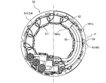
- FIG. 5 is a perspective view of a stator according to a second embodiment of the invention
- FIG. 5 is a front view of a stator according to a second embodiment of the invention
- FIG. 1 is a diagram showing an electric compressor 1 according to the first embodiment of the present invention.
- the electric compressor 1 is a horizontally mounted inverter-integrated electric compressor in which a compression mechanism 3 and an electric motor 5 are horizontally arranged in series in a housing 2 and an inverter 8 as a motor drive circuit is integrally provided. be.
- the electric compressor 1 is applied to, for example, a vehicle air conditioner, and constitutes a refrigeration cycle device by being incorporated in a refrigerant circuit through which refrigerant circulates, together with a condenser, a pressure reducer (expansion valve, etc.), and an evaporator.
- refrigerating machine oil lubricating oil
- the housing 2 of the electric compressor 1 includes a main housing 21, an inverter housing 22, an inverter cover 23 and a discharge housing 24.
- the main housing 21, the inverter housing 22, the inverter cover 23, and the discharge housing 24 are made of metal material, for example.
- the main housing 21 is cylindrical.
- a suction port 21a is formed on one end side (left side in FIG. 1) of the peripheral wall of the main housing 21 to suck the refrigerant from the evaporator side.
- the intake port 21a is provided in the upper portion of the main housing 21 and opens upward.
- the main housing 21 accommodates the compression mechanism 3 , the rotating shaft 4 and the electric motor 5 .
- the opening on the one end side of the main housing 21 is closed by the inverter housing 22 .
- the inverter housing 22 is fastened to the main housing 21 with bolts (not shown).
- the inverter housing 22 is formed in a cylindrical shape with a bottom, and its bottom wall constitutes a partition wall 7 that separates the inside of the main housing 21 from the inside of the inverter housing 22 .
- the inverter housing 22 accommodates the inverter 8 as a motor drive circuit.
- An inverter cover 23 closes the opening of the inverter housing 22 on the side opposite to the bottom wall portion.
- the inverter cover 23 is fastened to the inverter housing 22 with bolts (not shown).
- the opening on the other end side of the main housing 21 is closed by the discharge housing 24 .
- the discharge housing 24 is fastened to the main housing 21 with bolts (not shown).
- the discharge housing 24 is formed with a discharge port 24a for discharging the refrigerant to the condenser side and a discharge passage 24b for guiding the refrigerant to the discharge port 24a.
- the discharge port 24a is provided in the upper part of the discharge housing 24 and opens upward.
- the compression mechanism 3 is arranged on the side of the discharge housing 24 inside the main housing 21 .
- the compression mechanism 3 is driven by the rotation of the rotating shaft 4, takes in refrigerant sucked into the main housing 21 from the intake port 21a, compresses the refrigerant, and discharges the compressed refrigerant.
- the refrigerant discharged from the compression mechanism 3 is guided to the discharge port 24a through the discharge passage 24b and discharged from the discharge port 24a.
- a scroll-type compression mechanism including a fixed scroll and a movable scroll may be employed as the compression mechanism 3 .
- the rotating shaft 4 extends in the axial direction of the main housing 21 .
- the rotating shaft 4 is rotatably supported in the main housing 21 by a bearing (not shown) with one end connected to the compression mechanism 3 via the connecting portion 9 .
- the connecting portion 9 may be a crank mechanism that converts the rotary motion of the rotating shaft 4 into the orbiting motion of the orbiting scroll.
- the rotating shaft 4 rotates to cause the movable scroll to orbit relative to the fixed scroll. configured to dispense;
- the electric motor 5 is arranged on the inverter housing 22 side inside the main housing 21 . That is, the electric motor 5 is arranged in the main housing 21 at a position closer to the suction port 21a than the compression mechanism 3 is.
- the electric motor 5 is configured to rotate the rotating shaft 4 . In other words, the electric motor 5 is configured to drive the compression mechanism 3 via the rotating shaft 4 .
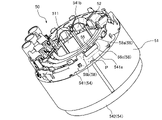
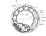
- FIGS. 1, 2A, and 2B are a perspective view and a front view of a stator 50 that constitutes the electric motor 5.
- FIG. As shown in FIGS. 1, 2A, and 2B, the electric motor 5 has a stator 50 having a stator core 51 and stator coils 52 and a rotor 53 .
- the stator core 51 is made of a magnetic material and has a cylindrical shape. Stator core 51 is supported by the inner wall of main housing 21 .
- the stator core 51 has a plurality (twelve in this example) of teeth 511 protruding radially inward (toward the rotating shaft 4). A plurality of teeth 511 are arranged at regular intervals in the circumferential direction.
- the stator coil 52 is constructed by winding a conducting wire 60 around the stator core 51 with concentrated winding. Specifically, stator coil 52 is configured by winding conductive wire 60 around each of a plurality of teeth 511 of stator core 51 .
- the conducting wire 60 is, for example, a linear conductor (core wire) on which an insulating coating is formed. Also, the conducting wire 60 is, in other words, a winding of the stator 50 .
- the stator 50 further has insulators 54 for electrically insulating the stator core 51 and the stator coils 52 .
- the insulator 54 is made of an insulating resin material. In this embodiment, the insulator 54 is divided into two insulator members 541 and 542 .
- FIG. 3A and 3B are a perspective view and a front view of the insulator member 541.
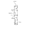
- FIG. 4 is a side view of the insulator member 541.
- the insulator member 541 has an annular base portion 541a and a projecting portion 541b extending radially inward from the base portion 541a.
- the projecting portion 541b is interposed between the tooth 511 and the stator coil 52 to insulate them.
- the configuration of the insulator member 542 may be the same as that of the insulator member 541 .
- a plurality of (twelve in this example) protrusions 55 for hooking the conductors 60 are formed at regular intervals in the circumferential direction at the end of the stator coil 52 on the coil end side of the base 541 a of the insulator member 541 .
- the portion P shown in FIGS. 1 to 4 faces the intake port 21a.
- the rotor 53 is arranged radially inward of (the plurality of teeth 511 of) the stator core 51 .
- a permanent magnet (not shown) is incorporated in the rotor 53 .
- the rotor 53 is formed in a cylindrical shape, and is fixed to the rotating shaft 4 with the rotating shaft 4 inserted through its hollow portion. That is, the rotor 53 is attached to the rotating shaft 4 and configured to rotate together with the rotating shaft 4 .
- the inverter 8 has various electronic components such as a power module including a smoothing capacitor and a plurality of power switching elements, and a circuit board on which the various electronic components are mounted.
- the inverter 8 is connected to an external power supply (vehicle battery or the like) via a first feeder line (not shown), and is powered by a second feeder line (not shown) that penetrates the partition wall 7 in an airtight and liquid-tight manner. It is connected to (the stator coil 52 of) the motor 5 .
- the inverter 8 outputs alternating current to the stator coil 52 of the electric motor 5 when supplied with the power supply voltage from the external power supply. That is, the stator coil 52 is energized. When the stator coil 52 is energized, a rotating magnetic field is generated, and the rotor 53 rotates in synchronization with the generated rotating magnetic field. As a result, the rotation shaft 4 rotates and the compression mechanism 3 is driven. Refrigerant is sucked into the main housing 21 through the suction port 21a.
- the refrigerant sucked into the main housing 21 from the intake port 21a first passes through the electric motor 5 and then through the compression mechanism 3 . That is, the refrigerant sucked from the suction port 21a passes through the electric motor 5 and the compression mechanism 3 in this order.
- the refrigerant sucked from the suction port 21a cools the electric motor 5 when passing through the electric motor 5, is compressed by the compression mechanism 3 when passing through the compression mechanism 3, and the compressed refrigerant is discharged from the discharge port 24a. is discharged from
- the protective member 58 that covers the portion 61 of the lead wire 60 that faces the intake port 21a is provided on the base portion 541a of the insulator member 541 .
- the protection member 58 is formed integrally with the base portion 541 a of the insulator member 541 .
- the portion 61 of the lead wire 60 is also a portion that connects the stator coils 52 adjacent in the circumferential direction.
- the protective member 58 has a U-shaped wall shape when viewed from the front of the insulator member 541 .
- the protection member 58 includes, for example, a pair of wall portions 58a and 58b facing each other with a space therebetween, and a wall portion 58c extending across the wall portions 58a and 58b.
- Each of the wall portions 58 a and 58 b extends radially outward from the base portion 541 a of the insulator member 541 .
- the wall portion 58 c extends substantially parallel to the base portion 541 a of the insulator member 541 .
- a wall portion 58c of the protective member 58 faces the intake port 21a.
- the portion 61 of the conductor 60 is hidden by the wall portion 58c of the protective member 58 when viewed from the suction port 21a. That is, the portion 61 of the lead wire 60 is arranged between the protrusion 55 of the insulator member 541 and the wall portion 58c of the protective member 58 .
- the protective member 58 covers the portion 61 of the lead wire 60 and the projecting portion 55 .
- the shape of the protective member 58 is the U-shaped wall, but the shape of the protective member 58 is not limited to this.
- the shape of the protection member 58 may be a wall shape having an arc shape when viewed from the front of the insulator member 541 .
- the electric compressor 1 has a stator core 51, a stator coil 52 formed by winding a conductor wire 60 around the stator core 51, and a rotor 53 attached to the rotating shaft 4.
- the stator coil It has an electric motor 5 that rotates a rotary shaft 4 via a rotor 53 by energization of 52, a compression mechanism 3 that is driven by the rotary shaft 4 and compresses the refrigerant, a suction port 21a and a discharge port 24a, and a rotary shaft.
- a housing 2 containing an electric motor 5 and a compression mechanism 3;
- the electric compressor 1 is configured such that the refrigerant sucked from the suction port 21a is compressed by the compression mechanism 3 and discharged from the discharge port 24a.
- the electric motor 5 is an inner rotor type motor in which a rotor 53 is arranged radially inside a cylindrical stator core 51 .
- the electric compressor 1 has a protective member 58 that covers a portion 61 of the lead wire 60 that faces the suction port 21a. Therefore, the protection member 58 prevents contamination contained in the fluid sucked from the suction port 21 a from colliding with the lead wire 60 . Therefore, direct impingement of the contamination on the conductor 60 is prevented.
- the electric motor 5 further has an insulator 54 for insulating the stator core 51 and the stator coil 52 .
- a protective member 58 is provided on the insulator 54 .
- the protective member 58 is formed integrally with the insulator 54 . Thereby, the protective member 58 can be assembled together with the insulator 54 .
- the portion 61 of the lead wire 60 is arranged between the protrusion 55 of the insulator 54 and the protective member 58 .
- the portion 61 of the lead wire 60 can be well protected from contamination contained in the fluid sucked from the suction port 21a.
- the protective member 58 is wall-shaped. Thereby, the protection member 58 can be configured simply.
- FIGS. 5A and 5B are a perspective view and a front view of the stator 50 in this embodiment. Differences from the first embodiment described above will be described.
- a protective member 59 is provided instead of the protective member 58 described above.
- the protective member 59 is made of mold resin.
- the portion 61 of the conductor 60 is molded (sealed) and covered with resin, and the molded portion functions as the protective member 59 .
- This resin includes, for example, an insulating thermosetting resin, such as an epoxy resin.
- the protective member 59 faces the intake port 21a.
- the portion 61 of the conductor 60 is hidden by the protective member 59 when viewed from the suction port 21a.
- the portion 61 of the lead wire 60 can be arranged between the protrusion 55 of the insulator member 541 and the protective member 59 .
- the protective member 59 may cover the portion 61 of the conductor 60 and the protrusion 55 .
- the protective member 59 is made of a molding resin that covers the portion 61 of the conductor 60 . Therefore, the portion 61 of the conductor 60 can be easily covered by molding with resin, and thus the portion 61 of the conductor 60 can be easily protected.
- the electric compressor according to the present invention is applied to a horizontal electric compressor in which the compression mechanism and the electric motor are horizontally arranged in series in the housing.
- the electric compressor according to the present invention may also be applied to a vertical electric compressor in which a compression mechanism and an electric motor are arranged vertically in series in a housing. .
Landscapes
- Engineering & Computer Science (AREA)
- Mechanical Engineering (AREA)
- General Engineering & Computer Science (AREA)
- Power Engineering (AREA)
- Compressor (AREA)
- Rotary Pumps (AREA)
Abstract
Description
図5A及び図5Bは、本実施形態におけるステータ50の斜視図及び正面図である。前述の第1実施形態と異なる点について説明する。
2 ハウジング
3 圧縮機構
4 回転軸
5 電動モータ
8 インバータ
21a 吸入ポート
24a 吐出ポート
50 ステータ
51 ステータコア
52 ステータコイル
53 ロータ
54 インシュレータ
55 突起部
58 保護部材
58a,58b,58c 壁部
59 保護部材
60 導線
61 部分
511 ティース
541,542 インシュレータ部材
541a 基部
541b 突出部
Claims (7)
- ステータコアと、導線が前記ステータコアに巻回されてなるステータコイルと、回転軸に取り付けられたロータと、を有し、前記ステータコイルへの通電によって前記ロータを介して前記回転軸を回転させる電動モータと、
前記回転軸によって駆動されて冷媒を圧縮する圧縮機構と、
吸入ポート及び吐出ポートを有すると共に、前記回転軸、前記電動モータ及び前記圧縮機構を収容するハウジングと、
を含み、
前記吸入ポートから吸入された冷媒が前記圧縮機構によって圧縮されて前記吐出ポートから吐出されるように構成された電動圧縮機であって、
前記導線のうち前記吸入ポートに対向する部分を覆う保護部材を有する、電動圧縮機。 - 前記電動モータは、円筒状の前記ステータコアの径方向内側に前記ロータが配置されているインナーロータ型モータである、請求項1に記載の電動圧縮機。
- 前記保護部材は、前記部分を覆うモールド樹脂により構成される、請求項1に記載の電動圧縮機。
- 前記電動モータは、前記ステータコアと前記ステータコイルとを絶縁するためのインシュレータを更に有し、
前記保護部材が前記インシュレータに設けられている、請求項1に記載の電動圧縮機。 - 前記保護部材が前記インシュレータに一体的に形成されている、請求項4に記載の電動圧縮機。
- 前記インシュレータの突起部と前記保護部材との間に前記部分が配置される、請求項4に記載の電動圧縮機。
- 前記保護部材が壁状である、請求項4に記載の電動圧縮機。
Priority Applications (3)
| Application Number | Priority Date | Filing Date | Title |
|---|---|---|---|
| US18/550,365 US12404848B2 (en) | 2021-03-23 | 2022-03-22 | Electric compressor |
| DE112022001633.7T DE112022001633T5 (de) | 2021-03-23 | 2022-03-22 | Elektrisch angetriebener Verdichter |
| CN202280021468.1A CN116997716B (en) | 2021-03-23 | 2022-03-22 | Electric compressor |
Applications Claiming Priority (2)
| Application Number | Priority Date | Filing Date | Title |
|---|---|---|---|
| JP2021-048798 | 2021-03-23 | ||
| JP2021048798A JP7743195B2 (ja) | 2021-03-23 | 2021-03-23 | 電動圧縮機 |
Publications (1)
| Publication Number | Publication Date |
|---|---|
| WO2022202802A1 true WO2022202802A1 (ja) | 2022-09-29 |
Family
ID=83395873
Family Applications (1)
| Application Number | Title | Priority Date | Filing Date |
|---|---|---|---|
| PCT/JP2022/013116 Ceased WO2022202802A1 (ja) | 2021-03-23 | 2022-03-22 | 電動圧縮機 |
Country Status (4)
| Country | Link |
|---|---|
| US (1) | US12404848B2 (ja) |
| JP (1) | JP7743195B2 (ja) |
| DE (1) | DE112022001633T5 (ja) |
| WO (1) | WO2022202802A1 (ja) |
Citations (8)
| Publication number | Priority date | Publication date | Assignee | Title |
|---|---|---|---|---|
| JP2000303953A (ja) * | 1999-04-20 | 2000-10-31 | Fujitsu General Ltd | 密閉型流体機械 |
| JP2008151050A (ja) * | 2006-12-19 | 2008-07-03 | Toyota Industries Corp | 電動コンプレッサ |
| JP2008301688A (ja) * | 2007-06-04 | 2008-12-11 | Toyota Industries Corp | 電動圧縮機 |
| JP2009191761A (ja) * | 2008-02-15 | 2009-08-27 | Denso Corp | 密閉型電動圧縮機 |
| JP2013060822A (ja) * | 2011-09-12 | 2013-04-04 | Toyota Industries Corp | 電動圧縮機 |
| JP2016200122A (ja) * | 2015-04-14 | 2016-12-01 | ジョンソンコントロールズ ヒタチ エア コンディショニング テクノロジー(ホンコン)リミテッド | 密閉型電動圧縮機 |
| JP2018119528A (ja) * | 2017-01-27 | 2018-08-02 | 株式会社豊田自動織機 | 電動圧縮機 |
| US20200232459A1 (en) * | 2019-01-18 | 2020-07-23 | Lg Electronics Inc. | Motor-operated compressor |
Family Cites Families (2)
| Publication number | Priority date | Publication date | Assignee | Title |
|---|---|---|---|---|
| AT10411U1 (de) * | 2007-05-31 | 2009-02-15 | Acc Austria Gmbh | Kältemittelverdichter |
| JP2020051328A (ja) | 2018-09-27 | 2020-04-02 | サンデン・オートモーティブコンポーネント株式会社 | 電動圧縮機 |
-
2021
- 2021-03-23 JP JP2021048798A patent/JP7743195B2/ja active Active
-
2022
- 2022-03-22 DE DE112022001633.7T patent/DE112022001633T5/de active Pending
- 2022-03-22 WO PCT/JP2022/013116 patent/WO2022202802A1/ja not_active Ceased
- 2022-03-22 US US18/550,365 patent/US12404848B2/en active Active
Patent Citations (8)
| Publication number | Priority date | Publication date | Assignee | Title |
|---|---|---|---|---|
| JP2000303953A (ja) * | 1999-04-20 | 2000-10-31 | Fujitsu General Ltd | 密閉型流体機械 |
| JP2008151050A (ja) * | 2006-12-19 | 2008-07-03 | Toyota Industries Corp | 電動コンプレッサ |
| JP2008301688A (ja) * | 2007-06-04 | 2008-12-11 | Toyota Industries Corp | 電動圧縮機 |
| JP2009191761A (ja) * | 2008-02-15 | 2009-08-27 | Denso Corp | 密閉型電動圧縮機 |
| JP2013060822A (ja) * | 2011-09-12 | 2013-04-04 | Toyota Industries Corp | 電動圧縮機 |
| JP2016200122A (ja) * | 2015-04-14 | 2016-12-01 | ジョンソンコントロールズ ヒタチ エア コンディショニング テクノロジー(ホンコン)リミテッド | 密閉型電動圧縮機 |
| JP2018119528A (ja) * | 2017-01-27 | 2018-08-02 | 株式会社豊田自動織機 | 電動圧縮機 |
| US20200232459A1 (en) * | 2019-01-18 | 2020-07-23 | Lg Electronics Inc. | Motor-operated compressor |
Also Published As
| Publication number | Publication date |
|---|---|
| JP2022147523A (ja) | 2022-10-06 |
| US12404848B2 (en) | 2025-09-02 |
| DE112022001633T5 (de) | 2024-03-14 |
| CN116997716A (zh) | 2023-11-03 |
| JP7743195B2 (ja) | 2025-09-24 |
| US20240305156A1 (en) | 2024-09-12 |
Similar Documents
| Publication | Publication Date | Title |
|---|---|---|
| US9212661B2 (en) | Electric compressor with the stator coils coated with resin, the resin having openings exposing the coils to the interior of the housing | |
| US20150056086A1 (en) | Electric compressor | |
| JP2002070743A (ja) | 冷媒圧縮用電動式圧縮機 | |
| CN103328823B (zh) | 压缩机用电动机及使用该电动机的电动压缩机 | |
| EP2309128A1 (en) | Electric compressor | |
| US20120251355A1 (en) | Motor-driven compressor | |
| EP2039933A1 (en) | Electric compressor | |
| JP2009222009A (ja) | 電動コンプレッサ | |
| JP6261271B2 (ja) | 密閉型電動圧縮機及び空気調和装置 | |
| JP6601246B2 (ja) | 電動圧縮機 | |
| JP2006042409A (ja) | モータ一体型コンプレッサ | |
| WO2023013433A1 (ja) | 電動圧縮機 | |
| JP2016217291A (ja) | 電動コンプレッサ及びその製造方法 | |
| JP7743195B2 (ja) | 電動圧縮機 | |
| JP5131032B2 (ja) | 電動圧縮機 | |
| CN116997716B (en) | Electric compressor | |
| KR101986450B1 (ko) | 전동 압축기 | |
| KR101959666B1 (ko) | 전동 압축기 | |
| JP6760182B2 (ja) | 電動圧縮機 | |
| JP2002180984A (ja) | 冷媒圧縮用電動式圧縮機 | |
| JP5931488B2 (ja) | 電動圧縮機 | |
| JP2004019586A (ja) | 電動圧縮機 | |
| WO2024190352A1 (ja) | 電動圧縮機 | |
| JP5271395B2 (ja) | 電動式圧縮機 | |
| CN120937218A (zh) | 制冷剂回路组件 |
Legal Events
| Date | Code | Title | Description |
|---|---|---|---|
| 121 | Ep: the epo has been informed by wipo that ep was designated in this application |
Ref document number: 22775585 Country of ref document: EP Kind code of ref document: A1 |
|
| WWE | Wipo information: entry into national phase |
Ref document number: 18550365 Country of ref document: US |
|
| WWE | Wipo information: entry into national phase |
Ref document number: 202280021468.1 Country of ref document: CN |
|
| WWE | Wipo information: entry into national phase |
Ref document number: 112022001633 Country of ref document: DE |
|
| 122 | Ep: pct application non-entry in european phase |
Ref document number: 22775585 Country of ref document: EP Kind code of ref document: A1 |
|
| WWG | Wipo information: grant in national office |
Ref document number: 18550365 Country of ref document: US |