WO2022202460A1 - 処理装置及び処理方法 - Google Patents
処理装置及び処理方法 Download PDFInfo
- Publication number
- WO2022202460A1 WO2022202460A1 PCT/JP2022/011456 JP2022011456W WO2022202460A1 WO 2022202460 A1 WO2022202460 A1 WO 2022202460A1 JP 2022011456 W JP2022011456 W JP 2022011456W WO 2022202460 A1 WO2022202460 A1 WO 2022202460A1
- Authority
- WO
- WIPO (PCT)
- Prior art keywords
- electrode
- pulse
- liquid
- voltage
- diode
- Prior art date
Links
- 238000000034 method Methods 0.000 title claims description 8
- 239000007788 liquid Substances 0.000 claims abstract description 39
- 239000001257 hydrogen Substances 0.000 claims description 23
- 229910052739 hydrogen Inorganic materials 0.000 claims description 23
- XLYOFNOQVPJJNP-UHFFFAOYSA-N water Substances O XLYOFNOQVPJJNP-UHFFFAOYSA-N 0.000 claims description 17
- UFHFLCQGNIYNRP-UHFFFAOYSA-N Hydrogen Chemical compound [H][H] UFHFLCQGNIYNRP-UHFFFAOYSA-N 0.000 claims description 8
- 239000000126 substance Substances 0.000 claims description 6
- 230000003213 activating effect Effects 0.000 claims description 2
- 238000005868 electrolysis reaction Methods 0.000 abstract description 16
- -1 hydrogen ions Chemical class 0.000 description 19
- LFQSCWFLJHTTHZ-UHFFFAOYSA-N Ethanol Chemical compound CCO LFQSCWFLJHTTHZ-UHFFFAOYSA-N 0.000 description 18
- 230000015556 catabolic process Effects 0.000 description 8
- 239000007789 gas Substances 0.000 description 5
- 239000001301 oxygen Substances 0.000 description 5
- 229910052760 oxygen Inorganic materials 0.000 description 5
- 238000011084 recovery Methods 0.000 description 5
- 238000003411 electrode reaction Methods 0.000 description 4
- 150000002431 hydrogen Chemical class 0.000 description 4
- 239000000203 mixture Substances 0.000 description 4
- 230000002123 temporal effect Effects 0.000 description 4
- 238000010586 diagram Methods 0.000 description 3
- 238000005516 engineering process Methods 0.000 description 3
- 238000003672 processing method Methods 0.000 description 3
- QVGXLLKOCUKJST-UHFFFAOYSA-N atomic oxygen Chemical compound [O] QVGXLLKOCUKJST-UHFFFAOYSA-N 0.000 description 2
- 230000000052 comparative effect Effects 0.000 description 2
- 239000003792 electrolyte Substances 0.000 description 2
- 239000008151 electrolyte solution Substances 0.000 description 2
- 238000004435 EPR spectroscopy Methods 0.000 description 1
- 235000011114 ammonium hydroxide Nutrition 0.000 description 1
- 230000004888 barrier function Effects 0.000 description 1
- 238000006243 chemical reaction Methods 0.000 description 1
- 239000013626 chemical specie Substances 0.000 description 1
- 239000013078 crystal Substances 0.000 description 1
- 238000006073 displacement reaction Methods 0.000 description 1
- 239000000463 material Substances 0.000 description 1
- 238000005259 measurement Methods 0.000 description 1
- 238000007254 oxidation reaction Methods 0.000 description 1
- 238000006722 reduction reaction Methods 0.000 description 1
- 238000001228 spectrum Methods 0.000 description 1
- 239000008399 tap water Substances 0.000 description 1
- 235000020679 tap water Nutrition 0.000 description 1
Images


Classifications
-
- C—CHEMISTRY; METALLURGY
- C01—INORGANIC CHEMISTRY
- C01B—NON-METALLIC ELEMENTS; COMPOUNDS THEREOF; METALLOIDS OR COMPOUNDS THEREOF NOT COVERED BY SUBCLASS C01C
- C01B3/00—Hydrogen; Gaseous mixtures containing hydrogen; Separation of hydrogen from mixtures containing it; Purification of hydrogen
- C01B3/02—Production of hydrogen or of gaseous mixtures containing a substantial proportion of hydrogen
-
- C—CHEMISTRY; METALLURGY
- C02—TREATMENT OF WATER, WASTE WATER, SEWAGE, OR SLUDGE
- C02F—TREATMENT OF WATER, WASTE WATER, SEWAGE, OR SLUDGE
- C02F1/00—Treatment of water, waste water, or sewage
- C02F1/46—Treatment of water, waste water, or sewage by electrochemical methods
- C02F1/461—Treatment of water, waste water, or sewage by electrochemical methods by electrolysis
-
- C—CHEMISTRY; METALLURGY
- C25—ELECTROLYTIC OR ELECTROPHORETIC PROCESSES; APPARATUS THEREFOR
- C25B—ELECTROLYTIC OR ELECTROPHORETIC PROCESSES FOR THE PRODUCTION OF COMPOUNDS OR NON-METALS; APPARATUS THEREFOR
- C25B1/00—Electrolytic production of inorganic compounds or non-metals
- C25B1/01—Products
- C25B1/02—Hydrogen or oxygen
- C25B1/04—Hydrogen or oxygen by electrolysis of water
-
- C—CHEMISTRY; METALLURGY
- C25—ELECTROLYTIC OR ELECTROPHORETIC PROCESSES; APPARATUS THEREFOR
- C25B—ELECTROLYTIC OR ELECTROPHORETIC PROCESSES FOR THE PRODUCTION OF COMPOUNDS OR NON-METALS; APPARATUS THEREFOR
- C25B15/00—Operating or servicing cells
- C25B15/02—Process control or regulation
-
- C—CHEMISTRY; METALLURGY
- C25—ELECTROLYTIC OR ELECTROPHORETIC PROCESSES; APPARATUS THEREFOR
- C25B—ELECTROLYTIC OR ELECTROPHORETIC PROCESSES FOR THE PRODUCTION OF COMPOUNDS OR NON-METALS; APPARATUS THEREFOR
- C25B9/00—Cells or assemblies of cells; Constructional parts of cells; Assemblies of constructional parts, e.g. electrode-diaphragm assemblies; Process-related cell features
Definitions
- the present disclosure relates to a processing apparatus and processing method for processing liquid.
- Patent Document 1 As a method of modifying the substance contained in the space, a method of generating low-temperature plasma in the electrode space is used (see Patent Document 1, for example). In order to improve the processing speed, a method of introducing a liquid into plasma to generate hydrogen or the like has also been tried (see, for example, Patent Documents 2 and 3).
- the present inventors recognized that further improving the efficiency of modifying substances was a problem and came up with the technology of the present disclosure.
- the present disclosure is made in view of such problems, and its purpose is to improve liquid processing technology.
- a processing apparatus includes a first electrode, a second electrode, and a pulse supply unit that applies a pulse voltage between the first electrode and the second electrode.
- the first electrode and the second electrode are in the liquid to be electrolyzed, and the pulse supply unit applies a negative going voltage pulse to the first electrode immediately after applying a positive going high voltage pulse to the first electrode. It has a function of causing current to flow from the second electrode toward the first electrode.
- Another aspect of the present disclosure is a liquid processing method. This method includes the steps of activating a substance contained in the liquid by applying a positive pulse voltage between a first electrode and a second electrode in the liquid; applying a pulsed voltage to cause a reversal current to flow from the second electrode towards the first electrode, thereby returning the activated material in the liquid to the surface of the first electrode.
- liquid processing technology can be improved.
- FIG. 1 It is a figure which shows roughly the structure of the processing apparatus which concerns on embodiment. It is a figure which shows typically the electrode reaction in the conventional electrolysis method. It is a figure which shows typically the electrode reaction in the electrolysis method by the processing apparatus of this Embodiment. It is a figure which shows the example of a circuit structure of a pulse supply part. It is a figure which shows the characteristic of the diode used with the processing apparatus of this Embodiment, and the characteristic of the diode used with the conventional electrolyzer. It is a figure which shows the time change of the voltage supplied to a process part, and an electric current. Fig.
- FIG. 3 shows the voltage V(1) supplied by the pulse supply, the current I(2) flowing through the processing unit and the power P(3);
- 1 is a diagram schematically showing the configuration of a processing device according to an embodiment of the present disclosure;
- FIG. It is a figure which shows a mode that the gas is generate
- FIG. 4 is a diagram showing temporal changes in the amount of OH radicals in pure water treated by the treatment apparatus according to the embodiment of the present disclosure;
- FIG. 10 is a diagram showing changes over time in the amount of radicals in various liquids processed by a processing apparatus according to an embodiment of the present disclosure;
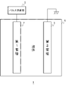
- FIG. 1 schematically shows the configuration of a processing device according to an embodiment.
- the processing device 1 includes a processing section 4 including a first electrode 2 and a second electrode 3 , and a pulse supply section 5 that applies a voltage pulse between the first electrode 2 and the second electrode 3 .
- the first electrode 2 and the second electrode 3 are in the liquid to be electrolyzed.
- the second electrode 3 is grounded, and voltage pulses are applied to the first electrode 2 from the pulse supply unit 5 in forward and reverse directions.
- the second electrode 3 may be connected to the pulse supply section 5 .
- a positive pulse may be applied to the second electrode 3 to achieve the same potential state as when a negative pulse is applied to the first electrode 2 .
- a voltage pulse may be a current pulse or a power pulse.
- the pulse supply unit 5 applies a voltage pulse in the negative direction to the first electrode 2 to generate a current from the second electrode 3 toward the first electrode 2.
- the liquid can be electrolyzed by a method completely different from the conventional electrolysis method, and the liquid can be reformed by generating active species such as OH radicals in the liquid.
- FIG. 2A schematically shows electrode reactions in conventional electrolysis.
- hydrogen ions H 2 + generated by an oxidation reaction on the anode side move to the cathode side in the electrolyte, receive electrons at the cathode, and become hydrogen H 2 .
- the hydroxide ions OH ⁇ produced by the reduction reaction on the cathode side move to the anode side in the electrolyte, lose electrons to the anode, and become oxygen O 2 or water H 2 O.
- the liquid to be electrolyzed must be an electrolytic solution.
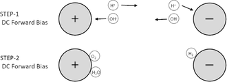
- FIG. 2B schematically shows the electrode reaction in the electrolysis method by the treatment apparatus 1 of this embodiment.
- Hydrogen ions H 2 + generated on the first electrode 2 (anode) side by the positive pulse (STEP-1) applied to the first electrode 2 from the pulse supply unit 5 are immediately followed by the negative pulse applied to the first electrode 2.
- STEP-2 By (STEP-2), it moves to the first electrode 2 (cathode), receives electrons at the first electrode 2 (cathode), and becomes hydrogen H 2 .
- FIG. 3A shows an example of the circuit configuration of the pulse supply section 5.
- the pulse supply unit 5 includes a pulse power supply 8 and a diode 9 serially connected to the pulse power supply 8 and the processing unit 4 .
- the diode 9 has a breakdown voltage lower than the voltage required to generate active species such as hydrogen ions and OH radicals from the liquid to be processed.
- the diode 9 has a function of causing a reverse current to flow to the processing unit 4 due to reverse recovery and avalanche breakdown characteristics when a voltage higher than the breakdown voltage is applied in the reverse direction after pulse power is applied in the forward direction.
- the diode 9 has a reverse recovery characteristic and a reverse current that can supply the current necessary for the hydrogen ions H + generated by the forward pulse power to receive electrons from the first electrode 2 and become hydrogen H2. Has tolerance.
- the diode 9 may be connected to the first electrode 2 or may be connected to the second electrode 3 .
- a diode may be connected in series for the purpose of preventing the current from flowing in the reverse direction.
- the current is applied in the opposite direction.
- a diode 9 having reverse recovery characteristics and reverse current resistance is connected in series.
- the purpose for which the diode 9 is provided in the processing apparatus 1 of the present disclosure is different from the purpose for which the diode is provided in conventional electrolyzers.
- the reverse recovery characteristics, reverse current withstand capability, etc. of the diode 9 provided in the processing apparatus 1 of the present disclosure are different from those of the diodes provided in the conventional electrolyzer.
- FIG. 3B shows the characteristics of the diode 9 and the characteristics of diodes used in conventional electrolyzers.
- Diodes used in conventional electrolysers have breakdown voltages as low as -100V.
- the reverse voltage side characteristics of the conventional diode are omitted.
- the diode 9 used in the processing apparatus 1 of this embodiment has a wider operating area than the diode used in the conventional electrolyzer.
- the diode 9, as described above, has a reverse breakdown voltage that is lower than the forward voltage required to generate hydrogen ions or the like from the liquid to be treated, which is about the same as the reverse voltage.
- the reverse breakdown voltage of the diode 9 may be, for example, approximately -4000 V as indicated by the solid line in the drawing, or may be lower than that as indicated by the broken line.
- the load characteristic generally seen in capacitive dielectric barrier discharge is exhibited at the initial stage of forward pulse application when a low voltage is applied.
- the present invention applies a forward high voltage steep pulse voltage to positively initiate the pulse electrolysis reaction of liquid. In that case, a recoil reverse voltage near its maximum value is instantaneously applied to the load and the diode 9 connected in series.
- the diode 9 has a reverse direction pulse voltage resistance performance corresponding to the maximum value of its reverse direction voltage, and the reverse direction voltage generated in the high resistance liquid after the previous forward direction pulse application while the reverse direction voltage is applied. It is required to have durability against resistive load displacement current characteristics in which directional current flows as a reverse current. Therefore, it is desirable that the diode 9 be made of a dislocation-free single crystal of Si. Diode 9 may be formed by connecting a plurality of diodes in series.
- FIG. 4A shows temporal changes in the voltage and current supplied to the processing unit 4.
- FIG. 4B shows the voltage V(1) supplied by the pulse supply unit 5, the current I(2) flowing through the processing unit 4, and the power P(3).
- the pulse supply unit 5 applies a positive pulse to the first electrode 2, the voltage sharply rises.
- the positive pulse has, for example, a half width of 200 ns, a voltage of 7 kV, and a dV/dt of 10 11 V/s. After that, the current also rises steeply. At this time, hydrogen ions H 2 + and OH radicals are generated from substances contained in the liquid near the surface of the first electrode 2 .
- the pulse supply unit 5 applies a negative pulse having a voltage similar to that of the positive pulse to the first electrode 2, the voltage of the negative pulse is higher than the reverse breakdown voltage of the diode 9, so the reverse recovery of the diode 9 Current flows in the opposite direction due to the avalanche breakdown characteristic.
- FIG. 5A schematically shows the configuration of a processing device 1 according to an embodiment of the present disclosure.
- the first electrode 2 and the second electrode 3 were immersed in water, the gas generated from each electrode was collected with an air collection bottle, and the collected gas was detected with a combustible gas detector.
- FIG. 5B shows gas generated from both electrodes.
- FIG. 5C shows the experimental results.
- pure water was electrolyzed by the electrolysis method of the present embodiment.
- the input voltage to the pulse supply unit 5 was 75 W
- the pulse frequency was 10 kpps
- the positive pulse voltage was 7.3 kV
- the negative pulse voltage was -4.0 kV
- the output power was 22 W.
- tap water was electrolyzed by conventional electrolysis.
- the DC voltage was 0.2 kV and the DC power was 2W.
- hydrogen evolved at the cathode and no hydrogen at the anode.
- hydrogen was generated at the anode (first electrode 2), and hydrogen was not generated at the cathode (second electrode 3).
- hydrogen is generated from electrodes opposite to those in the conventional electrolysis method.
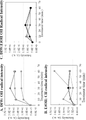
- FIG. 6 shows temporal changes in the amount of OH radicals in pure water treated by the treatment apparatus 1 according to the embodiment of the present disclosure.
- the amount of OH radicals is represented by the peak intensity of the spin of OH radicals in an electron spin resonance (ESR) spectrum. It was shown that the amount of OH radicals continued to increase with increasing treatment time.
- ESR electron spin resonance
- FIG. 7 shows temporal changes in the amount of radicals in various liquids treated by the treatment apparatus 1 according to the embodiment of the present disclosure. Measurement was performed three times for each of pure water, a mixture of water and ethanol, and ethanol.
- A indicates the amount of OH radicals in pure water.
- the treatment increases the amount of OH radicals.
- B indicates the amount of OH radicals in the mixture of water and ethanol.
- the treatment increases the amount of OH radicals.
- C indicates the amount of CH radicals in ethanol.
- the treatment increases the amount of CH radicals. It was shown that OH radicals and CH radicals can be generated by treating pure water, ethanol, and a mixture of water and ethanol with the treatment apparatus 1 according to the embodiment of the present disclosure.
- the present disclosure is applicable to processing apparatuses and processing methods for processing liquids.
Landscapes
- Chemical & Material Sciences (AREA)
- Engineering & Computer Science (AREA)
- Organic Chemistry (AREA)
- Chemical Kinetics & Catalysis (AREA)
- Electrochemistry (AREA)
- Metallurgy (AREA)
- Materials Engineering (AREA)
- Inorganic Chemistry (AREA)
- Combustion & Propulsion (AREA)
- General Chemical & Material Sciences (AREA)
- Life Sciences & Earth Sciences (AREA)
- Hydrology & Water Resources (AREA)
- Environmental & Geological Engineering (AREA)
- Water Supply & Treatment (AREA)
- Automation & Control Theory (AREA)
- Water Treatment By Electricity Or Magnetism (AREA)
Abstract
処理装置1は、第1電極2と、第2電極3と、第1電極2と第2電極3の間にパルス電圧を印加するパルス供給部5と、を備える。第1電極2と第2電極3は電気分解する液体中にあり、パルス供給部5は、第1電極2に正方向の高電圧パルスを印加した直後に、第1電極2に負方向の電圧パルスを印加して第2電極3から第1電極2に向かって電流を流す機能を有する。
Description
本開示は液体を処理するための処理装置及び処理方法に関する。
空間内に含まれる物質を改質する方法として、電極空間において低温プラズマを発生させる方法などが用いられる(例えば、特許文献1参照)。処理速度を向上させるために、液体をプラズマ中に投入して水素等を生成する方法も試行されている(例えば、特許文献2及び3参照)。
本発明者らは、物質を改質する効率を更に向上させることを課題として認識し、本開示の技術に想到した。
本開示は、このような課題に鑑みてなされ、その目的は、液体の処理技術を向上させることである。
上記課題を解決するために、本開示のある態様の処理装置は、第1電極と、第2電極と、第1電極と第2電極の間にパルス電圧を印加するパルス供給部と、を備える。第1電極と第2電極は電気分解する液体中にあり、パルス供給部は、第1電極に正方向の高電圧パルスを印加した直後に、第1電極に負方向の電圧パルスを印加して第2電極から第1電極に向かって電流を流す機能を有する。
本開示の別の態様は、液体の処理方法である。この方法は、液体中にある第1電極と第2電極の間に正パルス電圧を印加することにより、液体に含まれる物質を活性化させるステップと、第1電極と第2電極の間に負パルス電圧を印加して第2電極から第1電極に向かって反転電流を流すことにより、液体中で活性化された物質を第1電極の表面に戻すステップと、を備える。
本開示によれば、液体の処理技術を向上させることができる。
図1は、実施の形態に係る処理装置の構成を概略的に示す。処理装置1は、第1電極2と、第2電極3とを含む処理部4と、第1電極2と第2電極3との間に電圧パルスを印加するパルス供給部5とを備える。第1電極2と第2電極3は、電気分解する液体中にある。本図の例では、第2電極3は接地されており、第1電極2にパルス供給部5から正逆方向の電圧パルスが印加される。なお、第2電極3は、パルス供給部5に接続してもよい。この場合、第2電極3に正パルスを印加して、第1電極2に負パルスを印加したのと同じ電位状態を実現してもよい。電圧パルスは、電流パルス又は電力パルスであってもよい。
パルス供給部5は、第1電極2に正方向の高電圧パルスを印加した直後に、第1電極2に負方向の電圧パルスを印加して第2電極3から第1電極2に向かって電流を流す機能を有する。これにより、従来の電気分解法とは全く異なる方法により液体を電気分解することができるとともに、液体中にOHラジカルなどの活性種を発生させて液体を改質することができる。
図2Aは、従来の電気分解法における電極反応を模式的に示す。従来の電気分解では、陽極側の酸化反応により生じた水素イオンH+は、電解質中で陰極側に移動し、陰極で電子を受け取って水素H2となる。また、陰極側で還元反応により生じた水酸化物イオンOH-は、電解質中で陽極側に移動し、陽極に電子を奪われて酸素O2又は水H2Oとなる。水素イオンH+や水酸化物イオンOH-を電極間で移動させるために、電気分解の対象となる液体は電解液である必要がある。
図2Bは、本実施の形態の処理装置1による電気分解法における電極反応を模式的に示す。パルス供給部5から第1電極2に印加された正パルス(STEP-1)により第1電極2(陽極)側に生じた水素イオンH+は、直後に第1電極2に印加された負パルス(STEP-2)により第1電極2(陰極)に移動し、第1電極2(陰極)で電子を受け取って水素H2となる。また、STEP-1において第2電極3側に生じた水酸化物イオンOH-や酸素イオンO2-は、STEP-2において第2電極3(陽極)に移動し、第2電極3(陽極)に電子を奪われて酸素O2又は水H2Oとなる。
この電気分解法によれば、水素イオンH+や水酸化物イオンOH-や酸素イオンO2-は、電極間を移動するのではなく、電極近傍(おおむね1μm以下と推定される)のごく短い経路を移動するだけなので、液体を電気分解して水素H2などを発生させる効率を飛躍的に向上させることができる。また、上記のSTEP-1とSTEP-2をパルスパワーで実現することにより、上記のサイクルを素早く繰り返すことができるので、液体を電気分解して水素H2などを発生させる効率を飛躍的に向上させることができる。また、電極において発生した水素イオンH+や水酸化物イオンOH-や酸素イオンO2-などを電極間で移動させる必要が無いため、高効率で電気分解することが可能になる。また、電解液以外の電気伝導率が比較的小さい液体、例えば、水、エタノール、水とエタノールの混合物、アンモニア液なども電気分解することができる。なお、本発明による純水の電気分解では、各電極近傍において次の反応が生じるものと推定している。
陽極近傍:
4H2O-4e-→4H++4OH(4OH・)
4H++4e-→2H2↑
陰極近傍:
4H2O+4e-→2O2-+2OH-+2H+
2O2-+2OH-+2H+-4e-→O2↑+2H2O
陽極近傍:
4H2O-4e-→4H++4OH(4OH・)
4H++4e-→2H2↑
陰極近傍:
4H2O+4e-→2O2-+2OH-+2H+
2O2-+2OH-+2H+-4e-→O2↑+2H2O
水やエタノールなどの高抵抗な液体を電気分解するために高電圧パルスを印加すると、急峻な電圧変化を伴うパルス衝撃により液体に含まれる化学種が励起され、OHラジカルなどの活性種も発生させることができる。本実施の形態の処理装置1によれば、液体中にOHラジカルなどの活性種を継続的に発生させることができるので、液体を効率良く改質することができる。
図3Aは、パルス供給部5の回路構成の例を示す。パルス供給部5は、パルス電源8と、パルス電源8及び処理部4に直列に接続されたダイオード9とを含む。ダイオード9は、処理対象の液体から水素イオンやOHラジカルなどの活性種を発生させるために必要な電圧よりも低い降伏電圧を有する。ダイオード9は、順方向にパルスパワーが印加された後、逆方向に降伏電圧よりも高い電圧が印加されたときに、逆回復となだれ降伏特性により逆電流を処理部4に流す機能を果たす。ダイオード9は、順方向のパルスパワーによって生じた水素イオンH+が第1電極2から電子を受け取って水素H2になるのに必要な電流を供給することが可能な逆回復特性と逆方向電流耐量を有する。なお、ダイオード9は、第1電極2に接続されてもよいし、第2電極3に接続されてもよい。
従来の電気分解では、上述したように、陽極側で生じた水素イオンを陰極側に移動させるために、順方向に電流を流し続ける必要がある。そのため、逆方向に電流が流れないようにすることを目的として、ダイオードが直列に接続される場合がある。それに対して、本開示の処理装置1では、第1電極2側で生じた水素イオンH+を第1電極2に移動させるために、逆方向に電流を流すことを目的として、その目的に合った逆回復特性と逆方向電流耐量を有するダイオード9を直列に接続する。このように、本開示の処理装置1にダイオード9が備えられる目的は、従来の電気分解装置にダイオードが備えられる目的とは異なる。また、本開示の処理装置1に備えられるダイオード9の逆回復特性や逆方向電流耐量なども、従来の電気分解装置に備えられるダイオードとは異なる。
図3Bは、ダイオード9の特性と、従来の電気分解装置で使用されるダイオードの特性を示す。従来の電気分解装置で使用されるダイオードは、-100V程度の低い降伏電圧を有する。本図において、従来のダイオードの逆電圧側の特性は図示を省略している。本実施の形態の処理装置1で使用されるダイオード9は、従来の電気分解装置で使用されるダイオードよりも広い動作領域を有する。ダイオード9は、上述したように、処理対象の液体から水素イオンなどを発生させるために必要な順方向の電圧と同程度の逆方向の電圧よりも低い逆方向降伏電圧を有する。ダイオード9の逆方向降伏電圧は、例えば、図中実線で示すように、-4000V程度であってもよいし、破線で示すように、それよりも低くてもよい。なお、処理する液体の電気伝導率が小さい(高抵抗)場合、一般的に、低電圧印加時では順方向パルス印加初期には容量性の誘電体バリア放電でみられる負荷特性を示す。本発明は、液体のパルス電気分解反応を積極的に開始するために正方向高電圧急峻パルス電圧を印加するものである。その場合、その最大値近傍の反跳逆方向電圧が負荷と直列に接続されるダイオード9とに瞬時に印加される。そのため、該ダイオード9は、その逆方向電圧の最大値に対応する耐逆方向パルス電圧性能を有するとともに、逆方向電圧が印加されつつ先の順方向パルス印加後に高抵抗液中に生成される順方向通電電荷が逆電流として流れる抵抗負荷的変位電流特性への耐久性が求められる。したがって、ダイオード9は、Siの無転位単結晶で製造されたものであることが望ましい。ダイオード9は、複数のダイオードを直列に接続したものであってもよい。
図4Aは、処理部4に供給される電圧及び電流の時間変化を示す。図4Bは、パルス供給部5により供給される電圧V(1)、処理部4を流れる電流I(2)、及び電力P(3)を示す。パルス供給部5が第1電極2に正パルスを印加すると、電圧が急峻に立ち上がる。正パルスは、例えば、半値幅が200ns、電圧が7kV、dV/dtが1011V/sである。その後、電流も急峻に立ち上がる。このとき、第1電極2の表面近傍の液体に含まれる物質から水素イオンH+やOHラジカルなどが発生する。つづいて、パルス供給部5が第1電極2に、正パルスと同程度の電圧の負パルスを印加すると、負パルスの電圧はダイオード9の逆方向降伏電圧よりも高いので、ダイオード9の逆回復となだれ降伏特性により逆方向に電流が流れる。
[実施例]
図5Aは、本開示の実施例に係る処理装置1の構成を概略的に示す。第1電極2と第2電極3を水中に入れ、それぞれの電極から発生する気体を集気瓶で収集し、収集した気体を可燃性ガス検知器で検知した。図5Bは、両極から気体が発生している様子を示す。
図5Aは、本開示の実施例に係る処理装置1の構成を概略的に示す。第1電極2と第2電極3を水中に入れ、それぞれの電極から発生する気体を集気瓶で収集し、収集した気体を可燃性ガス検知器で検知した。図5Bは、両極から気体が発生している様子を示す。
図5Cは、実験結果を示す。実施例では、本実施の形態の電気分解法により純水を電気分解した。パルス供給部5への入力電圧は75W、パルス周波数は10kpps、正パルス電圧は7.3kV、負パルス電圧は-4.0kV、出力電力は22Wとした。比較実施例では、従来の電気分解法により水道水を電気分解した。直流電圧は0.2kV、直流電力は2Wとした。比較実施例では、陰極で水素が発生し、陽極では水素は発生しなかった。実施例では、陽極(第1電極2)で水素が発生し、陰極(第2電極3)では水素は発生しなかった。図2A及び図2Bに示したように、本実施の形態の電気分解法では、従来の電気分解法とは逆の電極から水素が発生することが示された。
図6は、本開示の実施例に係る処理装置1により処理した純水中のOHラジカルの量の時間変化を示す。OHラジカルの量は、電子スピン共鳴(Electron Spin Resonance:ESR)スペクトルにおけるOHラジカルのスピンのピーク強度で表す。処理時間が長くなるにつれて、OHラジカルの量が増加し続けていることが示された。
図7は、本開示の実施例に係る処理装置1により処理した様々な液体中のラジカルの量の時間変化を示す。純水、水とエタノールの混合物、エタノールのそれぞれについて3回ずつ測定を行った。Aは、純水中のOHラジカルの量を示す。処理によりOHラジカルの量が増加している。Bは、水とエタノールの混合物中のOHラジカルの量を示す。処理によりOHラジカルの量が増加している。Cは、エタノール中のCHラジカルの量を示す。処理によりCHラジカルの量が増加している。純水、エタノール、水とエタノールの混合物を本開示の実施例に係る処理装置1により処理することにより、OHラジカルやCHラジカルを発生させることができることが示された。
本開示は液体を処理するための処理装置及び処理方法に利用可能である。
1 処理装置、2 第1電極、3 第2電極、4 処理部、5 パルス供給部、8 パルス電源、9 ダイオード。
Claims (5)
- 第1電極と、
第2電極と、
前記第1電極と前記第2電極の間にパルス電圧を印加するパルス供給部と、
を備え、
前記第1電極と前記第2電極は電気分解する液体中にあり、
前記パルス供給部は、前記第1電極に正方向の高電圧パルスを印加した直後に、前記第1電極に負方向の電圧パルスを印加して前記第2電極から前記第1電極に向かって電流を流す機能を有する
処理装置。 - 前記第1電極の表面において前記液体が電気分解されて水素が発生する
請求項1に記載の処理装置。 - 前記液体中にOHラジカルを発生する
請求項1に記載の処理装置。 - 前記液体は、水である
請求項1から3のいずれかに記載の処理装置。 - 液体中にある第1電極と第2電極の間に正パルス電圧を印加することにより、前記液体に含まれる物質を活性化させるステップと、
前記第1電極と前記第2電極の間に負パルス電圧を印加して前記第2電極から前記第1電極に向かって電流を流すことにより、前記液体中で活性化された物質を前記第1電極の表面に戻すステップと、
を備える液体の処理方法。
Priority Applications (1)
| Application Number | Priority Date | Filing Date | Title |
|---|---|---|---|
| JP2023509037A JPWO2022202460A1 (ja) | 2021-03-25 | 2022-03-15 |
Applications Claiming Priority (2)
| Application Number | Priority Date | Filing Date | Title |
|---|---|---|---|
| JP2021-051176 | 2021-03-25 | ||
| JP2021051176 | 2021-03-25 |
Publications (1)
| Publication Number | Publication Date |
|---|---|
| WO2022202460A1 true WO2022202460A1 (ja) | 2022-09-29 |
Family
ID=83397172
Family Applications (1)
| Application Number | Title | Priority Date | Filing Date |
|---|---|---|---|
| PCT/JP2022/011456 WO2022202460A1 (ja) | 2021-03-25 | 2022-03-15 | 処理装置及び処理方法 |
Country Status (2)
| Country | Link |
|---|---|
| JP (1) | JPWO2022202460A1 (ja) |
| WO (1) | WO2022202460A1 (ja) |
Citations (5)
| Publication number | Priority date | Publication date | Assignee | Title |
|---|---|---|---|---|
| CN105858982A (zh) * | 2015-09-20 | 2016-08-17 | 大连双迪创新科技研究院有限公司 | 一种简易台式饮水机 |
| JP2017534764A (ja) * | 2014-11-19 | 2017-11-24 | テクニオン・リサーチ・アンド・ディベロップメント・ファウンデーション・リミテッド | 水電解による水素製造のための方法およびシステム |
| JP2019065350A (ja) * | 2017-09-29 | 2019-04-25 | 株式会社融合技術開発センター | 除菌水生成装置及び水回り機器 |
| WO2020241802A1 (ja) * | 2019-05-28 | 2020-12-03 | 三輪 有子 | 酸素水素混合ガス発生装置、吸引装置、酸素水素混合ガス発生方法、および酸素水素混合ガス |
| WO2020241656A1 (ja) * | 2019-05-28 | 2020-12-03 | 徳田 美幸 | 燃焼反応器および燃焼方法 |
-
2022
- 2022-03-15 WO PCT/JP2022/011456 patent/WO2022202460A1/ja active Application Filing
- 2022-03-15 JP JP2023509037A patent/JPWO2022202460A1/ja active Pending
Patent Citations (5)
| Publication number | Priority date | Publication date | Assignee | Title |
|---|---|---|---|---|
| JP2017534764A (ja) * | 2014-11-19 | 2017-11-24 | テクニオン・リサーチ・アンド・ディベロップメント・ファウンデーション・リミテッド | 水電解による水素製造のための方法およびシステム |
| CN105858982A (zh) * | 2015-09-20 | 2016-08-17 | 大连双迪创新科技研究院有限公司 | 一种简易台式饮水机 |
| JP2019065350A (ja) * | 2017-09-29 | 2019-04-25 | 株式会社融合技術開発センター | 除菌水生成装置及び水回り機器 |
| WO2020241802A1 (ja) * | 2019-05-28 | 2020-12-03 | 三輪 有子 | 酸素水素混合ガス発生装置、吸引装置、酸素水素混合ガス発生方法、および酸素水素混合ガス |
| WO2020241656A1 (ja) * | 2019-05-28 | 2020-12-03 | 徳田 美幸 | 燃焼反応器および燃焼方法 |
Also Published As
| Publication number | Publication date |
|---|---|
| JPWO2022202460A1 (ja) | 2022-09-29 |
Similar Documents
| Publication | Publication Date | Title |
|---|---|---|
| Shimizu et al. | A novel method of hydrogen generation by water electrolysis using an ultra-short-pulse power supply | |
| US20140231329A1 (en) | Liquid treatment device and liquid treatment method | |
| US8173075B2 (en) | Device for generation of pulsed corona discharge | |
| US9409800B2 (en) | Electric arc for aqueous fluid treatment | |
| Sato et al. | Water treatment with pulsed discharges generated inside bubbles | |
| KR101214441B1 (ko) | 수처리용 수중 방전 장치 | |
| Kawano et al. | Influence of pulse width on decolorization efficiency of organic dye by discharge inside bubble in water | |
| Tochikubo et al. | Study of wastewater treatment by OH radicals using DC and pulsed corona discharge over water | |
| WO2022202460A1 (ja) | 処理装置及び処理方法 | |
| JP2014210222A (ja) | 液体処理装置 | |
| Yasuoka et al. | Development of repetitive pulsed plasmas in gas bubbles for water treatment | |
| KR101280445B1 (ko) | 물 정화를 위한 수중 방전 장치 | |
| JP7356732B2 (ja) | 処理装置及び処理方法 | |
| Schriever | Uniform Direct‐Current Discharges in Atmospheric Pressure He/N2/CO2 Mixtures Using Gas Additives | |
| Takeda et al. | Morphology of high-frequency electrohydraulic discharge for liquid-solution plasmas | |
| Ruo-Bing et al. | Water treatment by the bipolar pulsed dielectric barrier discharge (DBD) in water-air mixture | |
| Chang et al. | UV and optical emissions generated by the pulsed arc electrohydraulic discharge | |
| JP2008095131A (ja) | 表面改質装置 | |
| Sidik et al. | Variation of Pattern and CavityDiameter of Aluminium Perforated with Single Glass Dielectric Barrier for Ozone Generation | |
| Hartmann et al. | Large area pulsed corona discharge in water for disinfection and pollution control | |
| Saressalo | Experimental study of the role of extrinsic and intrinsic vacuum arc breakdown mechanisms | |
| CN113423167B (zh) | 一种在液相中连续产生大体积等离子体的装置及方法 | |
| Dechthummarong et al. | An investigation of plasma activated water generated by 50 Hz half wave ac high voltage | |
| Wang et al. | High conductivity water treatment using water surface discharge with nonmetallic electrodes | |
| Plotnikov et al. | Effects of pulse frequency on liquid phase pulsed corona plasma discharge in ethanol |
Legal Events
| Date | Code | Title | Description |
|---|---|---|---|
| 121 | Ep: the epo has been informed by wipo that ep was designated in this application |
Ref document number: 22775251 Country of ref document: EP Kind code of ref document: A1 |
|
| WWE | Wipo information: entry into national phase |
Ref document number: 2023509037 Country of ref document: JP |
|
| NENP | Non-entry into the national phase |
Ref country code: DE |
|
| 122 | Ep: pct application non-entry in european phase |
Ref document number: 22775251 Country of ref document: EP Kind code of ref document: A1 |