WO2022202460A1 - Dispositif de traitement et procédé de traitement - Google Patents
Dispositif de traitement et procédé de traitement Download PDFInfo
- Publication number
- WO2022202460A1 WO2022202460A1 PCT/JP2022/011456 JP2022011456W WO2022202460A1 WO 2022202460 A1 WO2022202460 A1 WO 2022202460A1 JP 2022011456 W JP2022011456 W JP 2022011456W WO 2022202460 A1 WO2022202460 A1 WO 2022202460A1
- Authority
- WO
- WIPO (PCT)
- Prior art keywords
- electrode
- pulse
- liquid
- voltage
- diode
- Prior art date
Links
- 238000000034 method Methods 0.000 title claims description 8
- 239000007788 liquid Substances 0.000 claims abstract description 39
- 239000001257 hydrogen Substances 0.000 claims description 23
- 229910052739 hydrogen Inorganic materials 0.000 claims description 23
- XLYOFNOQVPJJNP-UHFFFAOYSA-N water Substances O XLYOFNOQVPJJNP-UHFFFAOYSA-N 0.000 claims description 17
- UFHFLCQGNIYNRP-UHFFFAOYSA-N Hydrogen Chemical compound [H][H] UFHFLCQGNIYNRP-UHFFFAOYSA-N 0.000 claims description 8
- 239000000126 substance Substances 0.000 claims description 6
- 230000003213 activating effect Effects 0.000 claims description 2
- 238000005868 electrolysis reaction Methods 0.000 abstract description 16
- -1 hydrogen ions Chemical class 0.000 description 19
- LFQSCWFLJHTTHZ-UHFFFAOYSA-N Ethanol Chemical compound CCO LFQSCWFLJHTTHZ-UHFFFAOYSA-N 0.000 description 18
- 230000015556 catabolic process Effects 0.000 description 8
- 239000007789 gas Substances 0.000 description 5
- 239000001301 oxygen Substances 0.000 description 5
- 229910052760 oxygen Inorganic materials 0.000 description 5
- 238000011084 recovery Methods 0.000 description 5
- 238000003411 electrode reaction Methods 0.000 description 4
- 150000002431 hydrogen Chemical class 0.000 description 4
- 239000000203 mixture Substances 0.000 description 4
- 230000002123 temporal effect Effects 0.000 description 4
- 238000010586 diagram Methods 0.000 description 3
- 238000005516 engineering process Methods 0.000 description 3
- 238000003672 processing method Methods 0.000 description 3
- QVGXLLKOCUKJST-UHFFFAOYSA-N atomic oxygen Chemical compound [O] QVGXLLKOCUKJST-UHFFFAOYSA-N 0.000 description 2
- 230000000052 comparative effect Effects 0.000 description 2
- 239000003792 electrolyte Substances 0.000 description 2
- 239000008151 electrolyte solution Substances 0.000 description 2
- 238000004435 EPR spectroscopy Methods 0.000 description 1
- 235000011114 ammonium hydroxide Nutrition 0.000 description 1
- 230000004888 barrier function Effects 0.000 description 1
- 238000006243 chemical reaction Methods 0.000 description 1
- 239000013626 chemical specie Substances 0.000 description 1
- 239000013078 crystal Substances 0.000 description 1
- 238000006073 displacement reaction Methods 0.000 description 1
- 239000000463 material Substances 0.000 description 1
- 238000005259 measurement Methods 0.000 description 1
- 238000007254 oxidation reaction Methods 0.000 description 1
- 238000006722 reduction reaction Methods 0.000 description 1
- 238000001228 spectrum Methods 0.000 description 1
- 239000008399 tap water Substances 0.000 description 1
- 235000020679 tap water Nutrition 0.000 description 1
Images


Classifications
-
- C—CHEMISTRY; METALLURGY
- C01—INORGANIC CHEMISTRY
- C01B—NON-METALLIC ELEMENTS; COMPOUNDS THEREOF; METALLOIDS OR COMPOUNDS THEREOF NOT COVERED BY SUBCLASS C01C
- C01B3/00—Hydrogen; Gaseous mixtures containing hydrogen; Separation of hydrogen from mixtures containing it; Purification of hydrogen
- C01B3/02—Production of hydrogen or of gaseous mixtures containing a substantial proportion of hydrogen
-
- C—CHEMISTRY; METALLURGY
- C02—TREATMENT OF WATER, WASTE WATER, SEWAGE, OR SLUDGE
- C02F—TREATMENT OF WATER, WASTE WATER, SEWAGE, OR SLUDGE
- C02F1/00—Treatment of water, waste water, or sewage
- C02F1/46—Treatment of water, waste water, or sewage by electrochemical methods
- C02F1/461—Treatment of water, waste water, or sewage by electrochemical methods by electrolysis
-
- C—CHEMISTRY; METALLURGY
- C25—ELECTROLYTIC OR ELECTROPHORETIC PROCESSES; APPARATUS THEREFOR
- C25B—ELECTROLYTIC OR ELECTROPHORETIC PROCESSES FOR THE PRODUCTION OF COMPOUNDS OR NON-METALS; APPARATUS THEREFOR
- C25B1/00—Electrolytic production of inorganic compounds or non-metals
- C25B1/01—Products
- C25B1/02—Hydrogen or oxygen
- C25B1/04—Hydrogen or oxygen by electrolysis of water
-
- C—CHEMISTRY; METALLURGY
- C25—ELECTROLYTIC OR ELECTROPHORETIC PROCESSES; APPARATUS THEREFOR
- C25B—ELECTROLYTIC OR ELECTROPHORETIC PROCESSES FOR THE PRODUCTION OF COMPOUNDS OR NON-METALS; APPARATUS THEREFOR
- C25B15/00—Operating or servicing cells
- C25B15/02—Process control or regulation
-
- C—CHEMISTRY; METALLURGY
- C25—ELECTROLYTIC OR ELECTROPHORETIC PROCESSES; APPARATUS THEREFOR
- C25B—ELECTROLYTIC OR ELECTROPHORETIC PROCESSES FOR THE PRODUCTION OF COMPOUNDS OR NON-METALS; APPARATUS THEREFOR
- C25B9/00—Cells or assemblies of cells; Constructional parts of cells; Assemblies of constructional parts, e.g. electrode-diaphragm assemblies; Process-related cell features
Definitions
- the present disclosure relates to a processing apparatus and processing method for processing liquid.
- Patent Document 1 As a method of modifying the substance contained in the space, a method of generating low-temperature plasma in the electrode space is used (see Patent Document 1, for example). In order to improve the processing speed, a method of introducing a liquid into plasma to generate hydrogen or the like has also been tried (see, for example, Patent Documents 2 and 3).
- the present inventors recognized that further improving the efficiency of modifying substances was a problem and came up with the technology of the present disclosure.
- the present disclosure is made in view of such problems, and its purpose is to improve liquid processing technology.
- a processing apparatus includes a first electrode, a second electrode, and a pulse supply unit that applies a pulse voltage between the first electrode and the second electrode.
- the first electrode and the second electrode are in the liquid to be electrolyzed, and the pulse supply unit applies a negative going voltage pulse to the first electrode immediately after applying a positive going high voltage pulse to the first electrode. It has a function of causing current to flow from the second electrode toward the first electrode.
- Another aspect of the present disclosure is a liquid processing method. This method includes the steps of activating a substance contained in the liquid by applying a positive pulse voltage between a first electrode and a second electrode in the liquid; applying a pulsed voltage to cause a reversal current to flow from the second electrode towards the first electrode, thereby returning the activated material in the liquid to the surface of the first electrode.
- liquid processing technology can be improved.
- FIG. 1 It is a figure which shows roughly the structure of the processing apparatus which concerns on embodiment. It is a figure which shows typically the electrode reaction in the conventional electrolysis method. It is a figure which shows typically the electrode reaction in the electrolysis method by the processing apparatus of this Embodiment. It is a figure which shows the example of a circuit structure of a pulse supply part. It is a figure which shows the characteristic of the diode used with the processing apparatus of this Embodiment, and the characteristic of the diode used with the conventional electrolyzer. It is a figure which shows the time change of the voltage supplied to a process part, and an electric current. Fig.
- FIG. 3 shows the voltage V(1) supplied by the pulse supply, the current I(2) flowing through the processing unit and the power P(3);
- 1 is a diagram schematically showing the configuration of a processing device according to an embodiment of the present disclosure;
- FIG. It is a figure which shows a mode that the gas is generate
- FIG. 4 is a diagram showing temporal changes in the amount of OH radicals in pure water treated by the treatment apparatus according to the embodiment of the present disclosure;
- FIG. 10 is a diagram showing changes over time in the amount of radicals in various liquids processed by a processing apparatus according to an embodiment of the present disclosure;
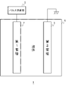
- FIG. 1 schematically shows the configuration of a processing device according to an embodiment.
- the processing device 1 includes a processing section 4 including a first electrode 2 and a second electrode 3 , and a pulse supply section 5 that applies a voltage pulse between the first electrode 2 and the second electrode 3 .
- the first electrode 2 and the second electrode 3 are in the liquid to be electrolyzed.
- the second electrode 3 is grounded, and voltage pulses are applied to the first electrode 2 from the pulse supply unit 5 in forward and reverse directions.
- the second electrode 3 may be connected to the pulse supply section 5 .
- a positive pulse may be applied to the second electrode 3 to achieve the same potential state as when a negative pulse is applied to the first electrode 2 .
- a voltage pulse may be a current pulse or a power pulse.
- the pulse supply unit 5 applies a voltage pulse in the negative direction to the first electrode 2 to generate a current from the second electrode 3 toward the first electrode 2.
- the liquid can be electrolyzed by a method completely different from the conventional electrolysis method, and the liquid can be reformed by generating active species such as OH radicals in the liquid.
- FIG. 2A schematically shows electrode reactions in conventional electrolysis.
- hydrogen ions H 2 + generated by an oxidation reaction on the anode side move to the cathode side in the electrolyte, receive electrons at the cathode, and become hydrogen H 2 .
- the hydroxide ions OH ⁇ produced by the reduction reaction on the cathode side move to the anode side in the electrolyte, lose electrons to the anode, and become oxygen O 2 or water H 2 O.
- the liquid to be electrolyzed must be an electrolytic solution.
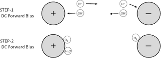
- FIG. 2B schematically shows the electrode reaction in the electrolysis method by the treatment apparatus 1 of this embodiment.
- Hydrogen ions H 2 + generated on the first electrode 2 (anode) side by the positive pulse (STEP-1) applied to the first electrode 2 from the pulse supply unit 5 are immediately followed by the negative pulse applied to the first electrode 2.
- STEP-2 By (STEP-2), it moves to the first electrode 2 (cathode), receives electrons at the first electrode 2 (cathode), and becomes hydrogen H 2 .
- FIG. 3A shows an example of the circuit configuration of the pulse supply section 5.
- the pulse supply unit 5 includes a pulse power supply 8 and a diode 9 serially connected to the pulse power supply 8 and the processing unit 4 .
- the diode 9 has a breakdown voltage lower than the voltage required to generate active species such as hydrogen ions and OH radicals from the liquid to be processed.
- the diode 9 has a function of causing a reverse current to flow to the processing unit 4 due to reverse recovery and avalanche breakdown characteristics when a voltage higher than the breakdown voltage is applied in the reverse direction after pulse power is applied in the forward direction.
- the diode 9 has a reverse recovery characteristic and a reverse current that can supply the current necessary for the hydrogen ions H + generated by the forward pulse power to receive electrons from the first electrode 2 and become hydrogen H2. Has tolerance.
- the diode 9 may be connected to the first electrode 2 or may be connected to the second electrode 3 .
- a diode may be connected in series for the purpose of preventing the current from flowing in the reverse direction.
- the current is applied in the opposite direction.
- a diode 9 having reverse recovery characteristics and reverse current resistance is connected in series.
- the purpose for which the diode 9 is provided in the processing apparatus 1 of the present disclosure is different from the purpose for which the diode is provided in conventional electrolyzers.
- the reverse recovery characteristics, reverse current withstand capability, etc. of the diode 9 provided in the processing apparatus 1 of the present disclosure are different from those of the diodes provided in the conventional electrolyzer.
- FIG. 3B shows the characteristics of the diode 9 and the characteristics of diodes used in conventional electrolyzers.
- Diodes used in conventional electrolysers have breakdown voltages as low as -100V.
- the reverse voltage side characteristics of the conventional diode are omitted.
- the diode 9 used in the processing apparatus 1 of this embodiment has a wider operating area than the diode used in the conventional electrolyzer.
- the diode 9, as described above, has a reverse breakdown voltage that is lower than the forward voltage required to generate hydrogen ions or the like from the liquid to be treated, which is about the same as the reverse voltage.
- the reverse breakdown voltage of the diode 9 may be, for example, approximately -4000 V as indicated by the solid line in the drawing, or may be lower than that as indicated by the broken line.
- the load characteristic generally seen in capacitive dielectric barrier discharge is exhibited at the initial stage of forward pulse application when a low voltage is applied.
- the present invention applies a forward high voltage steep pulse voltage to positively initiate the pulse electrolysis reaction of liquid. In that case, a recoil reverse voltage near its maximum value is instantaneously applied to the load and the diode 9 connected in series.
- the diode 9 has a reverse direction pulse voltage resistance performance corresponding to the maximum value of its reverse direction voltage, and the reverse direction voltage generated in the high resistance liquid after the previous forward direction pulse application while the reverse direction voltage is applied. It is required to have durability against resistive load displacement current characteristics in which directional current flows as a reverse current. Therefore, it is desirable that the diode 9 be made of a dislocation-free single crystal of Si. Diode 9 may be formed by connecting a plurality of diodes in series.
- FIG. 4A shows temporal changes in the voltage and current supplied to the processing unit 4.
- FIG. 4B shows the voltage V(1) supplied by the pulse supply unit 5, the current I(2) flowing through the processing unit 4, and the power P(3).
- the pulse supply unit 5 applies a positive pulse to the first electrode 2, the voltage sharply rises.
- the positive pulse has, for example, a half width of 200 ns, a voltage of 7 kV, and a dV/dt of 10 11 V/s. After that, the current also rises steeply. At this time, hydrogen ions H 2 + and OH radicals are generated from substances contained in the liquid near the surface of the first electrode 2 .
- the pulse supply unit 5 applies a negative pulse having a voltage similar to that of the positive pulse to the first electrode 2, the voltage of the negative pulse is higher than the reverse breakdown voltage of the diode 9, so the reverse recovery of the diode 9 Current flows in the opposite direction due to the avalanche breakdown characteristic.
- FIG. 5A schematically shows the configuration of a processing device 1 according to an embodiment of the present disclosure.
- the first electrode 2 and the second electrode 3 were immersed in water, the gas generated from each electrode was collected with an air collection bottle, and the collected gas was detected with a combustible gas detector.
- FIG. 5B shows gas generated from both electrodes.
- FIG. 5C shows the experimental results.
- pure water was electrolyzed by the electrolysis method of the present embodiment.
- the input voltage to the pulse supply unit 5 was 75 W
- the pulse frequency was 10 kpps
- the positive pulse voltage was 7.3 kV
- the negative pulse voltage was -4.0 kV
- the output power was 22 W.
- tap water was electrolyzed by conventional electrolysis.
- the DC voltage was 0.2 kV and the DC power was 2W.
- hydrogen evolved at the cathode and no hydrogen at the anode.
- hydrogen was generated at the anode (first electrode 2), and hydrogen was not generated at the cathode (second electrode 3).
- hydrogen is generated from electrodes opposite to those in the conventional electrolysis method.
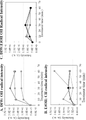
- FIG. 6 shows temporal changes in the amount of OH radicals in pure water treated by the treatment apparatus 1 according to the embodiment of the present disclosure.
- the amount of OH radicals is represented by the peak intensity of the spin of OH radicals in an electron spin resonance (ESR) spectrum. It was shown that the amount of OH radicals continued to increase with increasing treatment time.
- ESR electron spin resonance
- FIG. 7 shows temporal changes in the amount of radicals in various liquids treated by the treatment apparatus 1 according to the embodiment of the present disclosure. Measurement was performed three times for each of pure water, a mixture of water and ethanol, and ethanol.
- A indicates the amount of OH radicals in pure water.
- the treatment increases the amount of OH radicals.
- B indicates the amount of OH radicals in the mixture of water and ethanol.
- the treatment increases the amount of OH radicals.
- C indicates the amount of CH radicals in ethanol.
- the treatment increases the amount of CH radicals. It was shown that OH radicals and CH radicals can be generated by treating pure water, ethanol, and a mixture of water and ethanol with the treatment apparatus 1 according to the embodiment of the present disclosure.
- the present disclosure is applicable to processing apparatuses and processing methods for processing liquids.
Abstract
La présente invention concerne un dispositif de traitement 1 comprenant une première électrode 2, une seconde électrode 3, et une unité de fourniture d'impulsions qui applique une tension pulsée entre la première électrode 2 et la seconde électrode 3. La première électrode 2 et la seconde électrode 3 sont disposées dans un liquide qui met en œuvre l'électrolyse. L'unité de fourniture d'impulsions 5 a pour fonction d'appliquer une impulsion haute tension dans la direction positive à la première électrode 2, et immédiatement après, d'appliquer une impulsion de tension dans la direction négative à la première électrode 2 pour amener le courant à s'écouler de la seconde électrode 3 vers la première électrode 2.
Priority Applications (1)
| Application Number | Priority Date | Filing Date | Title |
|---|---|---|---|
| JP2023509037A JPWO2022202460A1 (fr) | 2021-03-25 | 2022-03-15 |
Applications Claiming Priority (2)
| Application Number | Priority Date | Filing Date | Title |
|---|---|---|---|
| JP2021-051176 | 2021-03-25 | ||
| JP2021051176 | 2021-03-25 |
Publications (1)
| Publication Number | Publication Date |
|---|---|
| WO2022202460A1 true WO2022202460A1 (fr) | 2022-09-29 |
Family
ID=83397172
Family Applications (1)
| Application Number | Title | Priority Date | Filing Date |
|---|---|---|---|
| PCT/JP2022/011456 WO2022202460A1 (fr) | 2021-03-25 | 2022-03-15 | Dispositif de traitement et procédé de traitement |
Country Status (2)
| Country | Link |
|---|---|
| JP (1) | JPWO2022202460A1 (fr) |
| WO (1) | WO2022202460A1 (fr) |
Citations (5)
| Publication number | Priority date | Publication date | Assignee | Title |
|---|---|---|---|---|
| CN105858982A (zh) * | 2015-09-20 | 2016-08-17 | 大连双迪创新科技研究院有限公司 | 一种简易台式饮水机 |
| JP2017534764A (ja) * | 2014-11-19 | 2017-11-24 | テクニオン・リサーチ・アンド・ディベロップメント・ファウンデーション・リミテッド | 水電解による水素製造のための方法およびシステム |
| JP2019065350A (ja) * | 2017-09-29 | 2019-04-25 | 株式会社融合技術開発センター | 除菌水生成装置及び水回り機器 |
| WO2020241802A1 (fr) * | 2019-05-28 | 2020-12-03 | 三輪 有子 | Dispositif de génération de mélange d'oxyhydrogène gazeux, appareil d'aspiration, procédé de génération de mélange d'oxyhydrogène gazeux, et mélange d'oxyhydrogène gazeux |
| WO2020241656A1 (fr) * | 2019-05-28 | 2020-12-03 | 徳田 美幸 | Réacteur de combustion et procédé de combustion |
-
2022
- 2022-03-15 WO PCT/JP2022/011456 patent/WO2022202460A1/fr active Application Filing
- 2022-03-15 JP JP2023509037A patent/JPWO2022202460A1/ja active Pending
Patent Citations (5)
| Publication number | Priority date | Publication date | Assignee | Title |
|---|---|---|---|---|
| JP2017534764A (ja) * | 2014-11-19 | 2017-11-24 | テクニオン・リサーチ・アンド・ディベロップメント・ファウンデーション・リミテッド | 水電解による水素製造のための方法およびシステム |
| CN105858982A (zh) * | 2015-09-20 | 2016-08-17 | 大连双迪创新科技研究院有限公司 | 一种简易台式饮水机 |
| JP2019065350A (ja) * | 2017-09-29 | 2019-04-25 | 株式会社融合技術開発センター | 除菌水生成装置及び水回り機器 |
| WO2020241802A1 (fr) * | 2019-05-28 | 2020-12-03 | 三輪 有子 | Dispositif de génération de mélange d'oxyhydrogène gazeux, appareil d'aspiration, procédé de génération de mélange d'oxyhydrogène gazeux, et mélange d'oxyhydrogène gazeux |
| WO2020241656A1 (fr) * | 2019-05-28 | 2020-12-03 | 徳田 美幸 | Réacteur de combustion et procédé de combustion |
Also Published As
| Publication number | Publication date |
|---|---|
| JPWO2022202460A1 (fr) | 2022-09-29 |
Similar Documents
| Publication | Publication Date | Title |
|---|---|---|
| Shimizu et al. | A novel method of hydrogen generation by water electrolysis using an ultra-short-pulse power supply | |
| US20140231329A1 (en) | Liquid treatment device and liquid treatment method | |
| US8173075B2 (en) | Device for generation of pulsed corona discharge | |
| US9409800B2 (en) | Electric arc for aqueous fluid treatment | |
| Sato et al. | Water treatment with pulsed discharges generated inside bubbles | |
| KR101214441B1 (ko) | 수처리용 수중 방전 장치 | |
| Kawano et al. | Influence of pulse width on decolorization efficiency of organic dye by discharge inside bubble in water | |
| Tochikubo et al. | Study of wastewater treatment by OH radicals using DC and pulsed corona discharge over water | |
| WO2022202460A1 (fr) | Dispositif de traitement et procédé de traitement | |
| JP2014210222A (ja) | 液体処理装置 | |
| Yasuoka et al. | Development of repetitive pulsed plasmas in gas bubbles for water treatment | |
| KR101280445B1 (ko) | 물 정화를 위한 수중 방전 장치 | |
| JP7356732B2 (ja) | 処理装置及び処理方法 | |
| Schriever | Uniform Direct‐Current Discharges in Atmospheric Pressure He/N2/CO2 Mixtures Using Gas Additives | |
| Takeda et al. | Morphology of high-frequency electrohydraulic discharge for liquid-solution plasmas | |
| Ruo-Bing et al. | Water treatment by the bipolar pulsed dielectric barrier discharge (DBD) in water-air mixture | |
| Chang et al. | UV and optical emissions generated by the pulsed arc electrohydraulic discharge | |
| JP2008095131A (ja) | 表面改質装置 | |
| Sidik et al. | Variation of Pattern and CavityDiameter of Aluminium Perforated with Single Glass Dielectric Barrier for Ozone Generation | |
| Hartmann et al. | Large area pulsed corona discharge in water for disinfection and pollution control | |
| Saressalo | Experimental study of the role of extrinsic and intrinsic vacuum arc breakdown mechanisms | |
| CN113423167B (zh) | 一种在液相中连续产生大体积等离子体的装置及方法 | |
| Dechthummarong et al. | An investigation of plasma activated water generated by 50 Hz half wave ac high voltage | |
| Wang et al. | High conductivity water treatment using water surface discharge with nonmetallic electrodes | |
| Plotnikov et al. | Effects of pulse frequency on liquid phase pulsed corona plasma discharge in ethanol |
Legal Events
| Date | Code | Title | Description |
|---|---|---|---|
| 121 | Ep: the epo has been informed by wipo that ep was designated in this application |
Ref document number: 22775251 Country of ref document: EP Kind code of ref document: A1 |
|
| WWE | Wipo information: entry into national phase |
Ref document number: 2023509037 Country of ref document: JP |
|
| NENP | Non-entry into the national phase |
Ref country code: DE |
|
| 122 | Ep: pct application non-entry in european phase |
Ref document number: 22775251 Country of ref document: EP Kind code of ref document: A1 |