WO2022202166A1 - 乗降人数カウントシステム、乗降人数カウント方法、及び、乗降人数カウントプログラム - Google Patents
乗降人数カウントシステム、乗降人数カウント方法、及び、乗降人数カウントプログラム Download PDFInfo
- Publication number
- WO2022202166A1 WO2022202166A1 PCT/JP2022/008918 JP2022008918W WO2022202166A1 WO 2022202166 A1 WO2022202166 A1 WO 2022202166A1 JP 2022008918 W JP2022008918 W JP 2022008918W WO 2022202166 A1 WO2022202166 A1 WO 2022202166A1
- Authority
- WO
- WIPO (PCT)
- Prior art keywords
- vehicle
- boarding
- count
- counting
- moving image
- Prior art date
- Legal status (The legal status is an assumption and is not a legal conclusion. Google has not performed a legal analysis and makes no representation as to the accuracy of the status listed.)
- Ceased
Links
Images






Classifications
-
- B—PERFORMING OPERATIONS; TRANSPORTING
- B61—RAILWAYS
- B61L—GUIDING RAILWAY TRAFFIC; ENSURING THE SAFETY OF RAILWAY TRAFFIC
- B61L25/00—Recording or indicating positions or identities of vehicles or trains or setting of track apparatus
- B61L25/02—Indicating or recording positions or identities of vehicles or trains
- B61L25/04—Indicating or recording train identities
-
- G—PHYSICS
- G07—CHECKING-DEVICES
- G07C—TIME OR ATTENDANCE REGISTERS; REGISTERING OR INDICATING THE WORKING OF MACHINES; GENERATING RANDOM NUMBERS; VOTING OR LOTTERY APPARATUS; ARRANGEMENTS, SYSTEMS OR APPARATUS FOR CHECKING NOT PROVIDED FOR ELSEWHERE
- G07C9/00—Individual registration on entry or exit
-
- G—PHYSICS
- G08—SIGNALLING
- G08G—TRAFFIC CONTROL SYSTEMS
- G08G1/00—Traffic control systems for road vehicles
- G08G1/01—Detecting movement of traffic to be counted or controlled
-
- G—PHYSICS
- G08—SIGNALLING
- G08G—TRAFFIC CONTROL SYSTEMS
- G08G1/00—Traffic control systems for road vehicles
- G08G1/123—Traffic control systems for road vehicles indicating the position of vehicles, e.g. scheduled vehicles; Managing passenger vehicles circulating according to a fixed timetable, e.g. buses, trains, trams
- G08G1/127—Traffic control systems for road vehicles indicating the position of vehicles, e.g. scheduled vehicles; Managing passenger vehicles circulating according to a fixed timetable, e.g. buses, trains, trams to a central station ; Indicators in a central station
-
- G—PHYSICS
- G16—INFORMATION AND COMMUNICATION TECHNOLOGY [ICT] SPECIALLY ADAPTED FOR SPECIFIC APPLICATION FIELDS
- G16Y—INFORMATION AND COMMUNICATION TECHNOLOGY SPECIALLY ADAPTED FOR THE INTERNET OF THINGS [IoT]
- G16Y10/00—Economic sectors
- G16Y10/40—Transportation
-
- G—PHYSICS
- G16—INFORMATION AND COMMUNICATION TECHNOLOGY [ICT] SPECIALLY ADAPTED FOR SPECIFIC APPLICATION FIELDS
- G16Y—INFORMATION AND COMMUNICATION TECHNOLOGY SPECIALLY ADAPTED FOR THE INTERNET OF THINGS [IoT]
- G16Y20/00—Information sensed or collected by the things
- G16Y20/20—Information sensed or collected by the things relating to the thing itself
-
- G—PHYSICS
- G16—INFORMATION AND COMMUNICATION TECHNOLOGY [ICT] SPECIALLY ADAPTED FOR SPECIFIC APPLICATION FIELDS
- G16Y—INFORMATION AND COMMUNICATION TECHNOLOGY SPECIALLY ADAPTED FOR THE INTERNET OF THINGS [IoT]
- G16Y40/00—IoT characterised by the purpose of the information processing
- G16Y40/10—Detection; Monitoring
Definitions
- the present invention relates to a boarding/alighting number counting system, a boarding/alighting number counting method, and a boarding/alighting number counting program.
- Patent Document 1 discloses an information providing system that provides users outside the route bus with the congestion status inside the route bus.
- This information providing system includes first wireless communication means, second wireless communication means, means for grasping the number of passengers in the vehicle, congestion information generating means, display means, and output means.
- a first wireless communication means is provided at each bus stop.
- the second radio communication means is provided on the route bus, performs radio communication with the first radio communication means, and transmits predetermined information regarding the route bus when the route bus is at the bus stop.
- the means for grasping the number of passengers in the bus grasps the number of passengers in the bus by detecting or estimating it.
- the congestion information generating means generates congestion status information of the route bus from the total number of passengers of the route bus and the number of passengers in the bus grasped by the passenger number grasping means.
- a display means is provided at each bus stop.
- the output means outputs the congestion status information in order to display the congestion status information on the display means of the bus stop where the route bus will stop next.
- the above-mentioned information provision system is a process for accurately grasping the number of people getting on and off the vehicle from the viewpoint of countermeasures against infectious diseases (with/after corona) such as the new coronavirus (COVID-19) in recent years.
- infectious diseases with/after corona
- COVID-19 new coronavirus
- a system for counting the number of boarding and alighting people includes an imaging unit that captures a moving image including an entrance and exit of a vehicle; a process of adding a detection frame corresponding to the person to the moving image, a process of tracking the movement of the person to which the detection frame is added on the moving image, and the entrance/exit on the moving image. a first count line set at a position corresponding to the front; a second count line set at a position in front of the boarding/alighting gate on the moving image and spaced apart from the first count line; and a processing unit capable of executing a process of counting the number of passengers in the vehicle based on the positional relationship between the person and the detection frame.
- a method for counting the number of people boarding and exiting comprises the steps of: capturing a moving image including an entrance and exit of a vehicle; detecting a person from the captured moving image; a step of adding the detection frame to the moving image; a step of tracking the movement of the person to which the detection frame is added on the moving image; a second count line set at a position in front of the door on the moving image and spaced apart from the first count line; and the detection frame of the tracked person. counting the number of passengers in the vehicle based on the positional relationship with the vehicle.
- a program for counting the number of boarding and alighting people captures a moving image including an entrance and exit of a vehicle, detects a person from the captured moving image, and detects a person according to the detected person.
- a frame is added to the moving image, the motion of the person to which the detection frame is added is tracked on the moving image, and a first detection is set at a position corresponding to in front of the boarding/alighting gate on the moving image.
- a second count line set at a position in front of the boarding/exit spaced from the first count line on the moving image, and the detection frame of the tracked person. and counting the number of people getting on and off the vehicle.
- the boarding/alighting people counting system, the boarding/alighting people counting method, and the boarding/alighting people counting program according to the present invention provide a first count line, a second count line, and a person detection frame on a moving image including a vehicle entrance/exit. number of passengers in the vehicle is counted based on the positional relationship of .
- the system for counting the number of people getting on and off, the method for counting the number of people getting on and off, and the program for counting the number of people getting on and off have the effect of being able to properly ascertain the number of people getting on and off the vehicle.
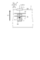
- FIG. 1 is a block diagram showing a schematic configuration of the boarding/alighting number counting system according to the embodiment.
- FIG. 2 is a schematic diagram for explaining the installation positions of the cameras provided in the embodiment.
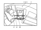
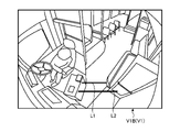
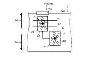
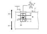
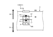
- FIG. 3 is a schematic diagram showing an example of a moving image in the boarding/alighting number counting system according to the embodiment.
- FIG. 4 is a schematic diagram showing an example of a moving image in the boarding/alighting number counting system according to the embodiment.
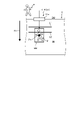
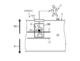
- FIG. 5 is a schematic diagram showing an example of boarding count in the boarding/alighting number counting system according to the embodiment.
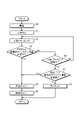
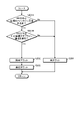
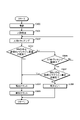
- FIG. 6 is a flow chart showing an example of processing in boarding counting in the boarding/alighting number counting system according to the embodiment.
- FIG. 1 is a block diagram showing a schematic configuration of the boarding/alighting number counting system according to the embodiment.
- FIG. 2 is a schematic diagram for explaining the installation positions of the cameras provided in the embodiment.
- FIG. 3 is a schematic diagram showing an
- FIG. 7 is a schematic diagram showing an example of reverse travel counting in the boarding/alighting number counting system according to the embodiment.
- FIG. 8 is a schematic diagram showing an example of reverse travel counting in the boarding/alighting number counting system according to the embodiment.
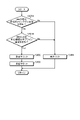
- FIG. 9 is a flow chart showing an example of processing for counting the number of people getting on and off in a reverse direction in the system for counting the number of people getting on and off according to the embodiment.
- FIG. 10 is a schematic diagram showing an example of prevention of wrong counting of people getting on and off backward in the system for counting the number of people getting on and off according to the embodiment.
- FIG. 11 is a flow chart showing an example of a process for preventing incorrect counting of people getting on and off backward in the system for counting the number of people getting on and off according to the embodiment.
- FIG. 12 is a schematic diagram showing an example of counting alighting in the boarding/alighting number counting system according to the embodiment.
- FIG. 13 is a flow chart showing an example of processing for counting getting on and off in the system for counting the number of people getting on and off according to the embodiment.
- FIG. 14 is a schematic diagram showing an example of reverse boarding counting in the boarding/alighting number counting system according to the embodiment.
- FIG. 15 is a schematic diagram showing an example of reverse boarding counting in the boarding/alighting number counting system according to the embodiment.
- FIG. 16 is a flow chart showing an example of processing for counting reverse trains in the system for counting the number of people boarding and alighting according to the embodiment.
- FIG. 17 is a schematic diagram showing an example of prevention of wrong boarding error counting in the boarding/alighting number counting system according to the embodiment.
- FIG. 18 is a flow chart showing an example of a process for preventing incorrect counting of reverse trains in the system for counting the number of people boarding and alighting according to the embodiment.
- the boarding/alighting number counting system 1 of the present embodiment is a system capable of counting the number of passengers inside the vehicle V based on the counted number of boarding/alighting people.
- the vehicle V to which the boarding/alighting number counting system 1 is applied is a moving body that travels on a road surface or the like. Typically, it is a fixed-route bus that repeatedly travels on a plurality of predetermined routes, a railroad vehicle that travels on a track, or the like. In the following description, the vehicle V is assumed to be a route bus.
- the number of people getting on and off the vehicle V is the number of people getting on and off the vehicle V.
- the number of passengers getting on and off the vehicle V typically includes the number of passengers corresponding to the number of people getting on the vehicle V and the number of people getting off the vehicle corresponding to the number of people getting off the vehicle.
- the number of passengers in the vehicle IN of the vehicle V is the number of passengers currently present in the vehicle IN.
- the number of passengers in the vehicle IN of the vehicle V typically corresponds to the number obtained by subtracting the number of alighting passengers from the number of boarding passengers.
- the boarding/alighting number counting system 1 counts up according to the number of passengers getting on and counts down according to the number of people getting off the vehicle, and as a result, can count the number of passengers.
- the passenger count system 1 of the present embodiment includes an in-vehicle device 10 mounted in a vehicle V and an analysis device 20 installed outside the vehicle V.
- the in-vehicle device 10 and the analysis device 20 The system 1 for counting the number of people getting on and off the vehicle outputs a moving image of the vehicle interior IN of the vehicle V captured by the on-vehicle device 10 to the analysis device 20, and constitutes a cooperative system for counting the number of people getting on and off the vehicle V on the analysis device 20 side.
- the boarding/alighting number counting system 1 can also output information based on the count result to another device D.
- FIG. The configuration of the boarding/alighting number counting system 1 will be described in detail below with reference to each drawing.
- the in-vehicle device 10 is a device that is mounted on the vehicle V and captures a moving image that is used by the analysis device 20 to count the number of passengers.
- the in-vehicle device 10 includes an imaging unit 11 , a data input/output unit 12 , a storage unit 13 and a processing unit 14 .
- the imaging unit 11, the data input/output unit 12, the storage unit 13, and the processing unit 14 are connected to communicate with each other via a network.
- the in-vehicle device 10 can be, for example, a so-called drive recorder that is mounted on the vehicle V and records various information, but is not limited to this.
- the imaging unit 11 is an imaging device that is provided in the vehicle interior IN of the vehicle V and captures a moving image including the entrance/exit V1 of the vehicle V from the vehicle interior IN.
- the boarding gate V1 of the vehicle V includes a boarding gate V1A and an alighting gate V1B.
- the boarding gate V1A is mainly used for boarding the vehicle V.
- the exit V1B is mainly used for getting off the vehicle V.
- the boarding gate V1A is located from the central part of the vehicle V to the rear part.
- the exit V1B is located at the front of the vehicle V. As shown in FIG.
- the imaging unit 11 of the present embodiment includes a first camera 11A and a second camera 11B.
- the first camera 11A captures a moving image of the boarding gate V1 including the boarding gate V1A.
- the second camera 11B captures a moving image including the exit V1B of the entrance V1.
- the first camera 11A is installed so as to have an angle of view capable of capturing an image of a person P (see FIG. 3 and the like) getting on and off through the boarding gate V1A from near the ceiling of the vehicle IN.
- the second camera 11B is installed so as to have an angle of view capable of capturing an image of a person P getting on and off the vehicle through the exit V1B from near the ceiling of the vehicle interior IN.
- the first camera 11A and the second camera 11B may be monocular cameras or stereo cameras.
- the images captured by the first camera 11A and the second camera 11B may be monochrome or color.
- the first camera 11A and the second camera 11B output moving image data representing captured moving images to the processing unit 14 .
- the boarding gate V1 is located at the rear portion of the vehicle V
- the boarding gate V1A is located at the rear portion of the vehicle V
- the boarding gate V1B is located at the front portion of the vehicle V.
- the data input/output unit 12 is an interface for inputting/outputting various data between another device (typically the analysis device 20) outside the vehicle-mounted device 10 and the vehicle-mounted device 10.
- the data input/output unit 12 may be implemented by, for example, a communication interface that transmits and receives various data to and from other devices outside the vehicle-mounted device 10 via wired or wireless communication.
- the data input/output unit 12 includes, for example, a hard disk drive (HDD), a solid state drive (SSD), a flexible disk (FD), a magneto-optical disk (Magneto-Optical disk), a CD-ROM, a DVD, a USB memory, an SD It may be realized by a recording medium interface that reads and writes various data to and from a recording medium such as card memory and flash memory.
- the data input/output unit 12 includes a wireless communication interface when counting the number of boarding and alighting passengers and the number of passengers in real time in accordance with the moving image captured by the imaging unit 11 .
- the data input/output unit 12 is configured by an interface other than the wireless communication interface when collectively counting the number of boarding and alighting passengers and the number of passengers for the moving image captured by the imaging unit 11 at a timely timing.
- the storage unit 13 is a storage circuit that stores various data.
- the storage unit 13 is implemented by, for example, a RAM (Random Access Memory), a semiconductor memory device such as a flash memory, a hard disk, an optical disk, or the like.
- the storage unit 13 stores, for example, programs for the in-vehicle device 10 to implement various functions.
- the programs stored in the storage unit 13 include a program for functioning the imaging unit 11 (the first camera 11A and the second camera 11B), a program for functioning the data input/output unit 12, a program for functioning the processing unit 14, and the like.
- the storage unit 13 stores moving image data representing moving images captured by the imaging unit 11, input/output data input/output via the data input/output unit 12, data necessary for various processes in the processing unit 14, and the like. Stores various data of These various data are read from the storage unit 13 by the processing unit 14 or the like as necessary.
- the processing unit 14 is a processing circuit that implements various processing functions in the in-vehicle device 10 .
- the processing unit 14 is realized by, for example, a processor.
- a processor means a circuit such as a CPU (Central Processing Unit), an MPU (Micro Processing Unit), an ASIC (Application Specific Integrated Circuit), and an FPGA (Field Programmable Gate Array).
- the processing unit 14 implements each processing function by executing a program read from the storage unit 13, for example.
- the processing unit 14 performs various arithmetic processing for capturing a moving image of the boarding gate V1 (boarding gate V1A, boarding gate V1B) of the vehicle V by the imaging unit 11 (first camera 11A, second camera 11B). It is viable.
- the processing unit 14 is triggered by the opening and closing operations of the boarding door V1a of the boarding gate V1A and the boarding gate V1b of the boarding gate V1B, and generates moving images of the boarding gate V1A and the boarding gate V1B by the first camera 11A and the second camera 11B. Start imaging.
- the processing unit 14 can execute a process of storing the moving image data representing the captured moving image in the storage unit 13 together with additional data representing the position, time, etc. of the vehicle V when the image was captured.
- the processing unit 14 can execute processing for outputting various data including moving image data to another device (typically the analysis device 20) outside the vehicle-mounted device 10 via the data input/output unit 12. .
- the analysis device 20 is provided outside the vehicle V and counts the number of passengers and the number of passengers of the vehicle V based on the moving image including the entrance/exit V1 of the vehicle V captured by the vehicle-mounted device 10 side.
- the analysis device 20 includes a data input/output unit 21 , a storage unit 22 and a processing unit 23 .
- the data input/output unit 21, the storage unit 22, and the processing unit 23 are connected so as to be able to communicate with each other via a network.
- the analysis device 20 may constitute a so-called cloud service type device (cloud server) implemented on a network, or may constitute a so-called stand-alone device separated from the network.
- the analysis device 20 constitutes a cloud service type device connected to a network when counting the number of boarding and alighting passengers and the number of passengers in real time in accordance with the moving image captured by the imaging unit 11 .
- the analysis device 20 is implemented by various computer devices such as a personal computer, a workstation, and a tablet terminal, for example.
- the analysis device 20 may be provided in a facility such as a business operator that manages the vehicle V, but it is not limited to this.
- the data input/output unit 21 is an interface for inputting/outputting various data between the analysis device 20 and other devices outside the analysis device 20 (typically the in-vehicle device 10 and the device D).
- the data input/output unit 21 is realized by a communication interface, a recording medium interface, etc., like the data input/output unit 12 described above.
- the data input/output unit 21 includes a wireless communication interface when counting the number of boarding and alighting passengers and the number of passengers in real time in accordance with the imaging of the moving image by the imaging unit 11 .
- the data input/output unit 21 is configured by an interface other than the wireless communication interface when collectively counting the number of boarding and alighting passengers and the number of passengers for the moving image captured by the imaging unit 11 at a timely timing. may be
- the storage unit 22 is a storage circuit that stores various data.
- the storage unit 22 is realized by a semiconductor memory device, a hard disk, an optical disc, or the like, like the storage unit 13 described above.
- the storage unit 22 stores, for example, programs for the analysis device 20 to implement various functions.
- the programs stored in the storage unit 22 include a program that causes the data input/output unit 21 to function, a program that causes the processing unit 23 to function, and the like. Further, the storage unit 22 stores various data such as input/output data input/output via the data input/output unit 21 and data required for various processes in the processing unit 23 .
- Input/output data input/output via the data input/output unit 21 includes, for example, moving image data representing a moving image captured by the image capturing unit 11 of the vehicle-mounted device 10 . These various data are read from the storage unit 22 by the processing unit 23 and the like as necessary. Note that the storage unit 22 may be implemented by a cloud server or the like connected to the analysis device 20 via a network.
- the processing unit 23 is a processing circuit that implements various processing functions in the analysis device 20 .
- the processing unit 23 is implemented by a processor, similar to the processing unit 14 described above.
- the processing unit 23 implements each processing function by executing a program read from the storage unit 22, for example.
- the processing unit 23 controls the boarding/alighting of the vehicle V based on the moving image of the boarding/alighting gate V1 (the boarding gate V1A and the boarding/alighting gate V1B) of the vehicle V captured by the imaging unit 11 (the first camera 11A and the second camera 11B).
- Various arithmetic processes for counting the number of people, the number of passengers, etc. can be executed.
- the processing unit 23 can execute processing for outputting information based on the count result to another device D via the data input/output unit 21 .
- the processing unit 23 displays the first count line L1 and the second It has a function for performing various processes for counting the number of passengers in the vehicle V based on the positional relationship between the count line L2 and the person P detection frame BB.
- the processing unit 23 of the present embodiment includes an input processing unit 23A, a person detection processing unit 23B, a tracking processing unit 23C, a count processing unit 23D, and an output processing unit 23E.
- the processing unit 23 executes a program read from the storage unit 22, for example, to perform each of the input processing unit 23A, the person detection processing unit 23B, the tracking processing unit 23C, the count processing unit 23D, and the output processing unit 23E. Realize the processing function.
- the input processing unit 23A is a part having a function capable of executing processing for inputting various data via the data input/output unit 12.
- the input processing unit 23 ⁇ /b>A can typically execute processing for inputting, via the data input/output unit 12 , moving image data representing a moving image captured by the imaging unit 11 of the vehicle-mounted device 10 .
- the input processing unit 23A may input the moving image data in real time as the moving image is captured by the imaging unit 11, or may input the moving image data ex post facto at an appropriate timing after the operation of the vehicle V ends. may be entered. Further, the input processing unit 23A can input moving image data from each of the vehicle-mounted devices 10 mounted on a plurality of vehicles V, respectively.
- the input processing unit 23A may temporarily store the input moving image data in the storage unit 22 .
- the person detection processing unit 23B detects a person P from the moving image captured by the imaging unit 11 and adds a detection frame BB corresponding to the detected person P to the moving image. It is the part that has the function to execute The person detection processing unit 23B executes processing related to detection of the person P and addition of the detection frame BB to the moving image of the moving image data captured by the imaging unit 11 and input by the input processing unit 23A.
- the person detection processing unit 23B detects a person P from the moving image using a known machine learning model or a known object detection algorithm such as "YOLOv4", and detects a position corresponding to the detected person P.
- a detection frame BB is added to .
- the detection frame BB is a rectangular frame having a size necessary to enclose the person P detected on the moving image, and is also called a "bounding box".
- the person detection processing unit 23B performs a process of enclosing an area in which the detected person P exists on the moving image with the detection frame (bounding box) BB.
- the tracking processing unit 23C is a part having a function capable of executing processing for tracking the movement of the person P to which the detection frame BB is added on the moving image.
- the tracking processing unit 23C executes processing for tracking the movement of the person P on the moving image to which the person P has been detected by the person detection processing unit 23B and the detection frame BB has been added.
- the tracking processing unit 23C uses known machine learning models and known tracking algorithms such as "Sort" and "Optical Flow estimation by Lucas Kanade method, Hom-Schunk method, etc.” The same person determination is performed for the person P to which is added, and the movement of the person P is tracked.
- the count processing unit 23D determines the positional relationship between the first count line L1 set on the moving image, the second count line L2 set on the moving image, and the detection frame BB of the tracked person P. It is a part having a function capable of executing processing for counting the number of passengers on the vehicle V.
- the counting processing unit 23D counts the number of people getting on and off the vehicle V based on the first count line L1, the second count line L2, and the detection frame BB for the moving image in which the movement BB of the person P is tracked by the tracking processing unit 23C. Executes a process to count .
- the count processing unit 23D counts both the number of people getting on and off the vehicle V and the number of people getting off the vehicle V as the number of people getting on and off.
- the count processing unit 23D of the present embodiment is a part having a function capable of executing a process of counting the number of passengers in the vehicle IN of the vehicle V based on the counted number of boarding and alighting passengers.
- the count processing unit 23D counts the number of passengers in the vehicle IN by subtracting the number of people getting off the vehicle from the number of people getting on and off. For example, the count processing unit 23D counts up according to the number of passengers getting on, and counts down according to the number of people getting off, so that the number of passengers can be counted.
- the logic for counting the number of passengers getting on and off by the count processing unit 23D will be described later in detail.
- the first count line L1 used for counting the number of boarding/alighting passengers by the count processing unit 23D is set at a position corresponding to the front of the boarding/alighting gate V1 on the moving image.
- the second count line L2 used for counting the number of boarding/alighting passengers by the count processing unit 23D is set at a position in front of the entrance/exit V1 and spaced apart from the first count line L1 on the moving image.
- the first count line L ⁇ b>1 and the second count line L ⁇ b>2 are, for example, the geometrical positional relationship of the aisle, the seat, the entrance/exit V ⁇ b>1 , the object in the vicinity of the entrance/exit V ⁇ b>1 , and the angle of view of the imaging unit 11 in the interior of the vehicle V. Positions, intervals, and shapes are set in advance as appropriate according to the requirements.
- the objects in the vicinity of the boarding/alighting gate V1 are, for example, the boarding door V1a, the boarding door V1b, the dangerous area when opening/closing, the fare box, the handrail, the step, and the like.
- the first count line L ⁇ b>1 and the second count line L ⁇ b>2 can be set using a moving image including the entrance/exit V ⁇ b>1 captured by the imaging unit 11 .
- a moving image including the entrance/exit V ⁇ b>1 captured by the imaging unit 11 for example, an object in the vicinity of the entrance/exit V1 is detected from the moving image using a known machine learning model or a known object detection algorithm such as those described above. It is also possible to set based on the detected object.
- the first count line L1 and the second count line L2 may, for example, be parallel to each other, or may not be parallel to each other. Also, the first count line L1 and the second count line L2 may be linear, curved, or curved, for example. Typically, the first count line L1 and the second count line L2 are appropriately positioned, spaced, and spaced according to actual vehicle evaluations and the like so that the number of passengers getting on and off can be properly counted by a counting logic to be described later. The shape should be adjusted and set. In the examples of FIGS. 3 and 4, the first count line L1 and the second count line L2 are both linear and set in a parallel positional relationship.
- the first count line L1 functions as a main count line for counting the number of passengers getting on and off when counting the number of passengers.
- the second count line L2 functions as a sub count line when counting the number of passengers getting on or off the vehicle, but does not count the other case.
- the first count line L1 is located outside the vehicle V from the second count line L2 at the boarding gate V1A, which is mainly used for boarding among the boarding gates V1. It is set on the OU side, that is, on the boarding door V1a side.
- the first count line L1 is located on the IN side of the vehicle V from the second count line L2 at the exit V1B of the entrance/exit V1 that is mainly used for exiting the vehicle. That is, it is set on the side opposite to the getting-off door V1b side.
- the boarding gate V1A and the boarding gate V1B may be arbitrarily specified by a business operator or the like who manages the vehicle V. It is also possible to specify In this case, the entrance/exit V1 detects the person P from the moving image using, for example, the above-described known machine learning model, known object detection algorithm, tracking algorithm, etc., and tracks the detected person P. Then, after vectorizing the tracking information of the person P, it is also possible to specify the boarding gate V1A and the getting-off gate V1B according to the sum of the movement vectors.
- the boarding gate V1 is assumed to be the boarding gate V1A mainly used for boarding.
- the getting on/off gate V1 is assumed to be the getting off gate V1B mainly used for getting off. can be specified.
- the output processing unit 23E is a part having a function capable of executing processing for outputting based on the count result of the count processing unit 23D.
- the output processing unit 23E executes, for example, a process of outputting information based on the count result of the count processing unit 23D to another device D outside the analysis device 20 via the data input/output unit 21.
- the device D to be output includes, for example, a display that outputs image information, a speaker that outputs sound information, a terminal device provided at a stop, a mobile terminal possessed by a user who can be a passenger, and various other devices. You can stay.
- the output processing unit 23E can output information based on the count result in various forms, such as the count result itself and congestion information according to the count result.
- FIG. 1 the direction from the OU outside the vehicle V to the IN side inside the vehicle may be referred to as a boarding direction D1
- the direction from the IN side to the OU outside the vehicle V may be referred to as an alighting direction D2.
- FIG. 5 is a schematic diagram showing an example of counting the number of passengers at the boarding gate V1A.
- the first count line L1 is set on the boarding door V1a side of the boarding gate V1A and functions as a main count line set to count both the number of passengers and the number of passengers getting off.
- the second count line L2 is set on the opposite side of the boarding gate V1A from the boarding door V1a side, and functions as a sub-count line set so as to count the number of passengers and not to count the number of passengers getting off.
- the count processing unit 23D determines whether the center coordinate P1 of the detection frame BB is aligned with either the first count line L1 or the second count line L2 of the vehicle V on the moving image including the boarding gate V1A.
- the center coordinates P1 are the coordinates of the center position of the detection frame BB.
- the count processing unit 23D detects that the center coordinate P1 of the detection frame BB of the detected person P has passed either the first count line L1 or the second count line L2 along the boarding direction D1. As a condition, it is detected that the person P has boarded the vehicle. Then, the count processing unit 23D counts up “1” as the number of passengers (counts by adding "1" to the number of passengers). In this case, the count processing unit 23D counts up the number of passengers of the vehicle V by "1" based on the counted number of passengers (adds "1" to the number of passengers and counts them).
- the count processing unit 23D cannot detect that the central coordinate P1 has passed through either the first count line L1 or the second count line L2 because the person P is hidden behind an object, for example. However, it can be detected that the person P has boarded on the condition that the person P has passed the other. Thereby, the count processing unit 23D can suppress omission in counting the number of passengers.
- the count processing unit 23D counts the number of passengers when the center coordinate P1 of the detection frame BB passes through either the first count line L1 or the second count line L2 on the moving image, and Even if the center coordinate P1 of the detection frame BB continues to pass the other of the first count line L1 or the second count line L2 in the same direction, the number of boarding/alighting passengers is not counted. That is, for example, after the central coordinate P1 passes the first count line L1 along the boarding direction D1 and counts the number of passengers, the count processing unit 23D passes the second count line L2 along the boarding direction D1. The number of passengers getting on and off is not counted, and the number of passengers is not counted up.
- the count processing unit 23D can prevent the number of passengers from being counted uncounted as described above, and also prevent the number of passengers from being duplicated when one person P rides. It is possible.
- the boarding/alighting number counting method in the boarding/alighting number counting system 1 shown in FIG. 6 includes an imaging step (step S0), a person detection step (step S1), a tracking step (step S2), and a counting step (steps S3 to S8).
- the processing related to each step described above is executed by the processing unit 14 of the in-vehicle device 10 and the processing unit 23 of the analysis device 20 .
- the processing unit 14 of the in-vehicle device 10 captures a moving image including the boarding gate V1A of the vehicle V using the first camera 11A of the imaging unit 11, for example, using the opening/closing operation of the boarding door V1a as a trigger, and captures the moving image.
- An imaging step (step S0) of outputting moving image data to the analyzing device 20 side is executed.
- the person detection processing unit 23B of the processing unit 23 of the analysis device 20 detects the person P from the moving image captured by the first camera 11A, and places a detection frame BB corresponding to the detected person P on the moving image. , a person detection step (step S1) is executed.
- the tracking processing unit 23C of the processing unit 23 of the analysis device 20 executes a tracking step (step S2) of tracking the movement of the person P to which the detection frame BB is added on the moving image.
- the count processing unit 23D of the processing unit 23 of the analysis device 20 executes counting steps (steps S3 to S8) for counting the number of passengers in the vehicle V.
- the count processing unit 23D detects that the central coordinate P1 of the detection frame BB of the detected person P has passed the first count line L1, which is the main count line, along the boarding direction D1, It is determined whether or not boarding of the person P has been detected (step S3).
- step S3 determines that the boarding of the person P has been detected (step S3: Yes)
- the count processing unit 23D counts the number of passengers on the vehicle V, and counts up the number of passengers (step S4).
- the count processing unit 23D counts up the number of passengers of the vehicle V based on the counted number of passengers (step S5), ends the current processing cycle, and shifts to the next processing cycle.
- step S3 determines whether tracking of the person P is being continued (step S6).
- step S6 determines that tracking of the person P is not continued (step S6: No)
- the process returns to step S2 and executes subsequent steps.
- step S6 determines that tracking of the person P is continued (step S6: Yes)
- the center coordinate P1 of the detection frame BB of the detected person P is the second count line which is a sub count line. Passing through L2 along the boarding direction D1 is detected, and it is determined whether boarding of the person P is detected (step S7).
- step S7: Yes the process proceeds to step S4 described above. If the count processing unit 23D determines that the boarding of the person P is not detected (step S7: No), the count processing unit 23D does not count the number of passengers (step S8), ends the current processing cycle, and starts the next processing cycle. Transition.
- the imaging step (step S0), the person detection step (step S1), the tracking step (step S2), and the counting steps (steps S3 to S8) in the method of counting the number of people getting on and off in FIG. a step of detecting a person from the moving image captured by the imaging unit and adding a detection frame corresponding to the detected person to the moving image; a step of tracking the movement of a person to which is added; a first count line set at a position corresponding to in front of the entrance/exit on the moving image; counting the number of people getting on and off the vehicle based on the positional relationship between the second count line set at an open position and the detection frame of the tracked person. It includes steps corresponding to the respective steps.
- This "method for counting the number of boarding and alighting passengers” can be realized by executing a “program for counting the number of boarding and alighting passengers" prepared in advance on a computer such as a personal computer and a work station.
- This "passenger number counting program” causes the computer to execute each process of the imaging step (step S0), the person detection step (step S1), the tracking step (step S2), and the counting step (steps S3 to S8). .
- ⁇ Reverse getting off count> 7 and 8 are schematic diagrams showing an example of counting processing of the number of people getting off in the reverse direction at the boarding gate V1A.
- the boarding gate V1A is the boarding gate V1 that is mainly used for boarding the vehicle V.
- a person P may exit the vehicle V in the opposite direction to the boarding direction D1.
- the count processing unit 23D on the moving image including the boarding gate V1A, as shown in FIG. Even when the vehicle V passes through the OU side, the number of people getting off the vehicle V is not counted as the number of passengers getting on and off, and as shown in FIG. In this case, the number of people getting off the vehicle V is counted as the number of people getting on and off.
- the count processing unit 23D does not count the number of people getting off the vehicle and does not count up the number of people getting off the vehicle.
- the count processing unit 23D suppresses the number of passengers from counting omissions as described above, and prevents the persons P staying near the second count line L2 after boarding from being erroneously counted as the number of people getting off. can be suppressed.
- the count processing unit 23D performs the detection on the condition that the center coordinates P1 of the detection frame BB of the detected person P have passed through the first count line L1 along the getting-off direction D2. It is detected that the person P got off the vehicle. Then, the count processing unit 23D counts up “1" as the number of people getting off (counts by adding "1" to the number of people getting off). In this case, the count processing unit 23D counts down the number of passengers of the vehicle V by "1" based on the counted number of people getting off (counts by subtracting "1" from the number of passengers).
- the count processing unit 23D can, for example, determine that even if there is a person P exiting the vehicle V in the opposite direction to the boarding direction D1 at the boarding gate V1A that is mainly used for boarding the vehicle V, the person P Alighting can be detected. As a result, the count processing unit 23D can suppress omission in counting the number of people getting off.
- processing procedure for counting backward alighting at the boarding gate V1A will be described.
- FIG. 9 the main steps of the process of counting the backward getting-off count will be extracted and explained.
- Processing related to each step shown in FIG. 9 is executed by the processing unit 23 of the analysis device 20 .
- the process of counting backward exits at the boarding gate V1A shown in FIG. 9 may be executed by being incorporated in the process described with reference to FIG. 6, or may be executed in parallel with the process.
- the count processing unit 23D detects and tracks the person P in steps S0, S1, and S2 of FIG. It is determined whether or not the person P has passed L1 along the getting-off direction D2, and the getting-off of the person P has been detected (step S201).
- the count processing unit 23D determines that it has detected that the person P has gotten off (step S201: Yes), it counts the number of people who have gotten off the vehicle V, and counts up the number of people who have gotten off (step S202).
- the count processing unit 23D counts down the number of passengers in the vehicle V based on the counted number of people getting off (step S203), ends the current processing cycle, and shifts to the next processing cycle.
- step S201 determines in step S201 that the person P has not gotten off the vehicle (step S201: No)
- the count processing unit 23D does not count the number of people getting off the vehicle (step S204), ends the current processing cycle, and performs the next processing. processing cycle.
- FIG. 10 is a schematic diagram showing an example of a process for preventing erroneous counting of the number of people getting off in the reverse direction at the boarding gate V1A.
- the count processing unit 23D counts the number of people getting off in the reverse direction based on the first count line L1 at the boarding gate V1A as described above, it is also possible to incorporate logic for preventing erroneous counting of the number of people getting off in the reverse direction.
- the count processing unit 23D determines that the center coordinate P1 of the detection frame BB moves the first count line L1 from the inside IN side of the vehicle to the outside OU side of the vehicle on the moving image including the boarding gate V1A. If at least a portion of the lower side of the detection frame BB, here, the lower side center coordinate P2 does not pass through the second count line L2 from the inside IN side of the vehicle V to the outside OU side of the vehicle V, the number of people getting in and out of the vehicle V If the second count line L2 passes from the inside IN side of the vehicle V to the outside OU side of the vehicle V, the number of getting off the vehicle V is counted as the number of people getting on and off.
- the lower side center coordinates P2 are the coordinates of the center position of the lower side of the rectangular detection frame BB.
- the count processing unit 23D determines that the lower side center coordinates P2 If the person P has not passed through L2 along the exit direction D2, it is not detected that the person P has exited the vehicle at this point. Therefore, at this time point, the count processing unit 23D does not count the number of people getting off the vehicle and does not count up the number of people getting off the vehicle.
- the count processing unit 23D detects that the person P has exited the vehicle on the condition that the lower side center coordinate P2 has passed the second count line L2 along the exit direction D2. Then, the count processing unit 23D counts up “one” as the number of people getting off the vehicle, and counts down the number of passengers of the vehicle V by "one” based on the counted number of people getting off.
- the count processing unit 23D can prevent, for example, erroneously counting people P who are pushed out to the boarding door V1a side and staying after boarding due to congestion in the car IN as the number of people getting off. .
- the count processing unit 23D detects the person P exiting the vehicle V in the opposite direction to the boarding direction D1 at the boarding gate V1A, distinguishing it from the person P staying near the boarding door V1a as described above. can do.
- the count processing unit 23D can both suppress omission in counting the number of people getting off the vehicle and suppress erroneous counting of the number of people getting off the vehicle.
- processing procedure for preventing wrong count of getting off backwards at the boarding gate V1A will be described.
- FIG. 11 the main steps of the process for preventing erroneous counting of getting off backwards will be extracted and explained.
- Processing related to each step shown in FIG. 11 is executed by the processing unit 23 of the analysis device 20 . 11 may be executed by being incorporated into the process described with reference to FIG. 6, or may be executed in parallel with the process.
- the count processing unit 23D detects and tracks the person P in steps S0, S1, and S2 of FIG. It is determined whether or not it has been detected that the vehicle has passed L1 along the exit direction D2 (step S201A).
- the count processing unit 23D determines that it has detected that the central coordinate P1 has passed through the first count line L1 (step S201A: Yes)
- the lower side central coordinate P2 of the detection frame BB is the second count line, which is the sub count line. Passing through the count line L2 along the getting-off direction D2 is detected, and it is determined whether or not getting-off of the person P has been detected (step S201B).
- step S201B determines that it has detected that the person P has gotten off the vehicle (step S201B: Yes). the process proceeds to step S202 described above.
- step S201A determines in step S201A that it has not detected that the central coordinate P1 has passed through the first count line L1 (step S201A: No), and in step S201B, the person P does not get off the vehicle. If it is determined that it is not detected (step S201B: No), the process proceeds to step S204 described above.
- the count processing unit 23D determines whether or not at least a part of the lower side of the detection frame BB has passed through the second count line L2 with reference to the lower side center coordinate P2. It may be determined whether or not the second count line L2 has been passed using coordinates other than the lower side center coordinate P2 or the entire lower side as a reference.
- FIG. 12 is a schematic diagram showing an example of counting the number of people getting off at the exit V1B.
- the first count line L1 is set on the opposite side of the exit door V1b at the exit V1B, and is the main count line set to count both the number of people getting off and the number of people getting off.
- the second count line L2 is set on the exit door V1b side of the exit V1B, and functions as a sub-count line that counts the number of people getting off and not counting the number of people getting on.
- the count processing unit 23D determines whether the center coordinate P1 of the detection frame BB is aligned with either the first count line L1 or the second count line L2 of the vehicle V on the moving image including the exit V1B.
- the number of people getting off from the vehicle V is counted as the number of people getting on and off.
- the count processing unit 23D detects that the center coordinate P1 of the detection frame BB of the detected person P has passed through either the first count line L1 or the second count line L2 along the getting-off direction D2. As a condition, it is detected that the person P has gotten off the vehicle. Then, the count processing unit 23D counts up “1" as the number of people getting off (counts by adding "1” to the number of people getting off). In this case, the count processing unit 23D counts down the number of passengers of the vehicle V by "1" based on the counted number of people getting off (counts by subtracting "1" from the number of passengers).
- the count processing unit 23D cannot detect that the central coordinate P1 has passed through either the first count line L1 or the second count line L2 because the person P is hidden behind an object, for example. However, it is possible to detect that the person P has gotten off the vehicle on the condition that the person P has passed the other vehicle. As a result, the count processing unit 23D can suppress omission in counting the number of people getting off.
- the count processing unit 23D counts the number of passengers when the center coordinate P1 of the detection frame BB passes through either the first count line L1 or the second count line L2 on the moving image, and Even if the center coordinate P1 of the detection frame BB continues to pass the other of the first count line L1 or the second count line L2 in the same direction, the number of boarding/alighting passengers is not counted. That is, for example, after the center coordinate P1 passes the first count line L1 along the exit direction D2 and counts the number of people getting off, the count processing unit 23D passes the second count line L2 along the exit direction D2. The number of people getting on and off is not counted, and the number of people getting off is not counted up.
- the count processing unit 23D can suppress the counting omission of the number of people getting off the car as described above, and can also suppress the overlapping counting of the number of people getting off the car with respect to the number of people getting off the car by one person P. It is possible.
- the method of counting the number of passengers in the passenger count system 1 shown in FIG. 13 includes an imaging step (step S300), a person detection step (step S301), a tracking step (step S302), and a counting step (steps S303 to S308).
- the processing related to each step described above is executed by the processing unit 14 of the in-vehicle device 10 and the processing unit 23 of the analysis device 20 .
- the processing unit 14 of the in-vehicle device 10 captures a moving image including the exit V1B of the vehicle V with the second camera 11B of the imaging unit 11, for example, triggered by the opening/closing operation of the exit door V1b, and captures the moving image.
- An imaging step (step S300) of outputting moving image data to the analyzing device 20 side is executed.
- the person detection processing unit 23B of the processing unit 23 of the analysis device 20 detects the person P from the moving image captured by the second camera 11B, and places a detection frame BB corresponding to the detected person P on the moving image. , a person detection step (step S301) is executed.
- the tracking processing unit 23C of the processing unit 23 of the analysis device 20 executes a tracking step (step S302) of tracking the movement of the person P to which the detection frame BB is added on the moving image.
- the count processing unit 23D of the processing unit 23 of the analysis device 20 executes counting steps (steps S303 to S308) for counting the number of people getting off the vehicle V and the number of passengers.
- the count processing unit 23D detects that the center coordinate P1 of the detection frame BB of the detected person P has passed through the first count line L1, which is the main count line, along the getting-off direction D2. It is determined whether or not getting off of the person P has been detected (step S303).
- step S303 Yes
- step S304 the count processing unit 23D determines that it has detected that the person P has gotten off
- the count processing unit 23D counts down the number of passengers in the vehicle V based on the counted number of people getting off (step S305), ends the current processing cycle, and shifts to the next processing cycle.
- step S303 determines whether tracking of the person P is being continued. If the count processing unit 23D determines that tracking of the person P is not continued (step S306: No), the process returns to step S302 and executes subsequent steps.
- the center coordinate P1 of the detection frame BB of the detected person P is the second count line which is a sub count line. It is determined whether or not it is detected that the person P has passed L2 along the getting-off direction D2 (step S307).
- step S307: Yes the process proceeds to step S304 described above. If it is determined that the person P has not gotten off the vehicle (step S307: No), the count processing unit 23D does not count the number of people getting off the vehicle (step S308), ends the current processing cycle, and starts the next processing cycle. Transition.
- the imaging step (step S300), the person detection step (step S301), the tracking step (step S302), and the counting steps (steps S303 to S308) in the method of counting the number of people getting on and off in FIG. a step of detecting a person from the moving image captured by the imaging unit and adding a detection frame corresponding to the detected person to the moving image; a step of tracking the movement of a person to which is added; a first count line set at a position corresponding to in front of the entrance/exit on the moving image; counting the number of people getting on and off the vehicle based on the positional relationship between the second count line set at an open position and the detection frame of the tracked person. It includes steps corresponding to the respective steps.
- This "method for counting the number of boarding and alighting passengers” can be realized by executing a “program for counting the number of boarding and alighting passengers" prepared in advance on a computer such as a personal computer and a work station.
- This "passenger number counting program” causes the computer to execute each process of the above-described imaging step (step S300), person detection step (step S301), tracking step (step S302), and counting step (steps S303 to S308). .
- FIG. 14 and FIG. 15 are schematic diagrams showing an example of counting the number of reverse passengers at the exit V1B.
- the exit V1B is the entrance/exit V1 that is mainly used for getting off the vehicle V, and there may be a person P getting on the vehicle V in the opposite direction to the getting off direction D2 at the exit V1B.
- the count processing unit 23D determines that the center coordinate P1 of the detection frame BB is aligned with the second count line L2 from the outside OU side of the vehicle to the inside of the vehicle, as shown in FIG. Even when the vehicle V passes through the IN side, the number of passengers in the vehicle V is not counted as the number of passengers getting on and off, and as shown in FIG. In this case, the number of passengers on the vehicle V is counted as the number of passengers getting on and off.
- the count processing unit 23D detects the detected person P even if the center coordinate P1 of the detection frame BB passes through the second count line L2 along the boarding direction D1. Then, it is not detected that the person P has boarded the vehicle. Therefore, at this time, the count processing unit 23D does not count the number of passengers and does not count up the number of passengers.
- the count processing unit 23D suppresses the counting omission of the number of people getting off the vehicle as described above, and also prevents the person P staying near the second count line L2 after getting off from the vehicle from being erroneously counted as the number of people getting on. can be suppressed.
- the count processing unit 23D performs the detection on the condition that the center coordinate P1 of the detection frame BB of the detected person P has passed through the first count line L1 along the boarding direction D1. It is detected that a person P has boarded the vehicle. Then, the count processing unit 23D counts up “1" as the number of passengers (counts by adding "1" to the number of passengers). In this case, the count processing unit 23D counts up the number of passengers of the vehicle V by "1" based on the counted number of passengers (adds "1" to the number of passengers and counts them).
- the count processing unit 23D for example, even if there is a person P getting on the vehicle V in the opposite direction to the getting off direction D2 at the exit V1B mainly used for getting off the vehicle V, the person P It is possible to detect that you have boarded the vehicle. Thereby, the count processing unit 23D can suppress omission in counting the number of passengers.
- FIG. 16 the procedure for counting reverse boarding at the exit V1B will be described.
- FIG. 16 the main steps of the process of counting backward travel are extracted and explained. Processing related to each step shown in FIG. 16 is executed by the processing unit 23 of the analysis device 20 .
- the process of counting backward travel at the exit V1B shown in FIG. 16 may be executed by being incorporated into the process described with reference to FIG. 13, or may be executed in parallel with the process.
- the count processing unit 23D detects, for example, in steps S300, S301, and S302 of FIG. It is determined whether or not it is detected that the person P has passed L1 along the boarding direction D1 (step S401).
- step S401 determines that the boarding of the person P has been detected (step S401: Yes)
- the count processing unit 23D counts the number of passengers on the vehicle V, and counts up the number of passengers (step S402).
- the count processing unit 23D counts up the number of passengers of the vehicle V based on the counted number of passengers (step S403), ends the current processing cycle, and shifts to the next processing cycle.
- step S401 determines in step S401 that the boarding of the person P has not been detected (step S401: No)
- the count processing unit 23D does not count the number of passengers (step S404), ends the current processing cycle, and performs the next processing. processing cycle.
- FIG. 17 is a schematic diagram showing an example of a process for preventing erroneous counting of the number of people traveling backwards at the exit V1B.
- the count processing unit 23D can incorporate a logic for preventing erroneous counting of the number of reverse passengers.
- the count processing unit 23D determines that the center coordinate P1 of the detection frame BB is aligned with the first count line L1 from the outside OU side of the vehicle to the inside IN side of the vehicle on the moving image including the exit V1B. If at least a part of the upper side of the detection frame BB, here, the upper side center coordinate P3 does not pass the second count line L2 from the outside OU side of the vehicle V to the inside IN side of the vehicle V, the number of people getting in and out of the vehicle V If the second count line L2 passes from the outside OU side of the vehicle V to the inside IN side of the vehicle V, the number of people getting on and off the vehicle V is counted.
- the upper side center coordinates P3 are the coordinates of the center position of the upper side of the rectangular detection frame BB.
- the count processing unit 23D determines that the upper side center coordinates P3 If the person P has not passed L2 along the boarding direction D1, it is not detected at this point that the person P has boarded. Therefore, at this time, the count processing unit 23D does not count the number of passengers and does not count up the number of passengers.
- the count processing unit 23D detects that the person P has boarded on the condition that the upper side center coordinate P3 has passed the second count line L2 along the boarding direction D1. Then, the count processing unit 23D counts up “one” as the number of passengers, and counts up “one” the number of passengers of the vehicle V based on the counted number of passengers.
- the count processing unit 23D can prevent, for example, the person P from being pushed back toward the exit door V1b after exiting the vehicle due to congestion in the OU outside the vehicle and staying there, from being erroneously counted as the number of passengers. .
- the count processing unit 23D detects the person P who gets on from the vehicle V in the opposite direction to the getting off direction D2 at the getting off gate V1B, distinguishing it from the person P staying near the getting off door V1b as described above. can do.
- the count processing unit 23D can both suppress omission in counting the number of passengers and suppress erroneous counting of the number of passengers.
- the count processing unit 23D detects, for example, in steps S300, S301, and S302 of FIG. It is determined whether or not it has been detected that the vehicle has passed L1 along the boarding direction D1 (step S401A).
- the count processing unit 23D determines that it has detected that the central coordinate P1 has passed the first count line L1 (step S401A: Yes)
- the upper side central coordinate P3 of the detection frame BB is the second count line, which is the sub count line. It is determined whether or not it is detected that the person P has passed the count line L2 along the boarding direction D1 (step S401B).
- step S401B determines that it has detected that the person P has boarded (step S401B: Yes). the process proceeds to step S402 described above.
- step S401A determines in step S401A that it has not detected that the central coordinate P1 has passed through the first count line L1 (step S401A: No), and in step S401B, it determines that the person P has boarded. If it is determined that it is not detected (step S401B: No), the process proceeds to step S404 described above.
- the count processing unit 23D determines whether or not at least a part of the upper side of the detection frame BB has passed through the second count line L2 with reference to the upper side center coordinate P3. It may be determined whether or not the second count line L2 has been passed with reference to coordinates other than the center coordinate P3 of the upper side of or the entire upper side.
- the boarding/alighting number counting system 1, the boarding/alighting number counting method, and the boarding/alighting number counting program described above are performed on a moving image including the boarding/alighting gate V1 of the vehicle V, the first count line L1, the second count line L2, Based on the positional relationship between the person P and the detection frame BB, the number of passengers in the vehicle V is counted.
- the system 1 for counting the number of people getting on and off, the method for counting the number of people getting on and off, and the program for counting the number of people getting on and off can properly grasp the number of people getting on and off the vehicle V.
- the boarding/alighting number counting system 1, the boarding/alighting number counting method, and the boarding/alighting number counting program can be used to determine the counted number of boarding/alighting passengers of the vehicle V in various ways, such as real-time congestion status analysis and vehicle V usage trend analysis. It can be used for various purposes.
- the boarding/alighting number counting system 1, the boarding/alighting number counting method, and the boarding/alighting number counting program described above can count the number of passengers inside the vehicle V based on the counted number of boarding/alighting passengers.
- the boarding/alighting number counting system 1, the boarding/alighting number counting method, and the boarding/alighting number counting program can utilize the counted number of passengers of the vehicle V for various purposes as described above.
- the center coordinate P1 of the detection frame BB of the person P is the first count line L1 or the second count line L1.
- the number of passengers is counted when one of the count lines L2 is passed, and the number of passengers is not counted when the other of the first count line L1 or the second count line L2 is passed in the same direction.
- the boarding/alighting number counting system 1, the boarding/alighting number counting method, and the boarding/alighting number counting program suppress the omission of counting the number of boarding/alighting people, and the number of boarding/alighting people is duplicated with respect to the boarding/alighting of one person P. You can prevent it from happening.
- the boarding/alighting number counting system 1, the boarding/alighting number counting method, and the boarding/alighting number counting program can accurately count the number of boarding/alighting people, can grasp the number of boarding/alighting people more accurately, and can increase the number of passengers. can be accurately grasped.
- the boarding/alighting people counting system 1, the boarding/alighting people counting method, and the boarding/alighting people counting program are designed so that the center coordinate P1 of the detection frame BB of the person P is on the first count line L1 or the second count line L2.
- the boarding/alighting number counting system 1, the boarding/alighting number counting method, and the boarding/alighting number counting program are performed when the center coordinate P1 of the detection frame BB of the person P passes through the second count line L2 from the vehicle IN side to the vehicle outside OU side. Even if there is, the number of people getting off the vehicle V is not counted as the number of people getting on and off, and the number of people getting off is counted when the first count line L1 is passed after that.
- the boarding/alighting number counting system 1, the boarding/alighting number counting method, and the boarding/alighting number counting program suppress the omission of counting the number of passengers, and then mistake the person P staying near the second count line L2 after boarding. It is possible to suppress counting as the number of people getting off.
- the system 1 for counting the number of people getting on and off, the method for counting the number of people getting on and off, and the program for counting the number of people getting on and off will not count even if there is a person P going backwards at the boarding gate V1A and exiting the vehicle V. It can be counted as the number of people getting off.
- the boarding/alighting number counting system 1, the boarding/alighting number counting method, and the boarding/alighting number counting program can more accurately count the number of boarding/alighting people, can grasp the number of boarding/alighting people more accurately, and can eventually count the number of passengers. can be grasped more accurately.
- the passenger count system 1, the boarding and alighting passenger count method, and the boarding and alighting passenger count program described above are configured so that the center coordinate P1 of the detection frame BB of the person P is aligned with the first count line L1 from the vehicle IN side to the vehicle exterior OU side. If the center coordinate P2 of the lower side of the detection frame BB does not pass through the second count line L2 from the vehicle IN side to the vehicle exterior OU side, the number of people getting off the vehicle is not counted, and the second count line L2 is passed. If so, the number of people getting off the vehicle V can be counted as the number of people getting on and off.
- the boarding/alighting number counting system 1, the boarding/alighting number counting method, and the boarding/alighting number counting program prevent erroneously counting the person P who is pushed out to the boarding door V1a side after boarding and stays as the number of alighting passengers.
- a person P getting off the vehicle V going in the opposite direction to the boarding direction D1 at the boarding gate V1A can be detected separately from the person P staying near the boarding door V1a.
- the boarding/alighting number counting system 1, the boarding/alighting number counting method, and the boarding/alighting number counting program can both suppress the omission of counting the number of alighting passengers and suppress the erroneous counting of the number of alighting passengers.
- the boarding/alighting number counting system 1, the boarding/alighting number counting method, and the boarding/alighting number counting program can more accurately count the number of boarding/alighting people, can grasp the number of boarding/alighting people more accurately, and can eventually count the number of passengers. can be grasped more accurately.
- the boarding/alighting people counting system 1, the boarding/alighting people counting method, and the boarding/alighting people counting program are designed so that the center coordinate P1 of the detection frame BB of the person P is on the first count line L1 or the second count line L2.
- the boarding/alighting number counting system 1, the boarding/alighting number counting method, and the boarding/alighting number counting program are performed when the center coordinate P1 of the detection frame BB of the person P passes through the second count line L2 from the vehicle exterior OU side to the vehicle interior IN side. Even if there is, the number of passengers from the vehicle V is not counted as the number of passengers getting on and off, and the number of passengers is counted after passing the first count line L1.
- the boarding/alighting number counting system 1, the boarding/alighting number counting method, and the boarding/alighting number counting program suppress the omission of counting the number of people getting off the vehicle, and then mistake the person P staying near the second count line L2 after getting off the vehicle. It is possible to suppress counting as the number of passengers.
- the system 1 for counting the number of people getting on and off, the method for counting the number of people getting on and off, and the program for counting the number of people getting on and off will fail to count even if there is a person P going backwards into the vehicle V at the exit V1B. It can be counted as the number of passengers.
- the boarding/alighting number counting system 1, the boarding/alighting number counting method, and the boarding/alighting number counting program can more accurately count the number of boarding/alighting people, can grasp the number of boarding/alighting people more accurately, and can eventually count the number of passengers. can be grasped more accurately.
- the center coordinate P1 of the detection frame BB of the person P is set to the first count line L1 from the outside OU side to the inside IN side. If the center coordinate P3 of the upper side of the detection frame BB does not pass through the second count line L2 from the outside OU side to the inside IN side, the number of passengers is not counted, and the second count line L2 is passed. If so, the number of people getting on and off the vehicle V can be counted as the number of people getting on and off.
- the system 1 for counting the number of people getting on and off the method for counting the number of people getting on and off, and the program for counting the number of people getting on and off prevent the person P from being pushed back toward the getting off door V1b after getting off the vehicle and staying there from being counted incorrectly as the number of people getting on and off.
- the person P who gets on the vehicle V in the opposite direction to the getting off direction D2 at the getting off door V1b can be detected separately from the person P staying near the getting off door V1b.
- the boarding/alighting number counting system 1, the boarding/alighting number counting method, and the boarding/alighting number counting program can simultaneously suppress omission of counting the number of passengers and suppression of erroneous counting of the number of passengers.
- the boarding/alighting number counting system 1, the boarding/alighting number counting method, and the boarding/alighting number counting program can more accurately count the number of boarding/alighting people, can grasp the number of boarding/alighting people more accurately, and can eventually count the number of passengers. can be grasped more accurately.
- the boarding/alighting number counting system 1 configured as described above is useful, for example, from the viewpoint of countermeasures against infectious diseases such as the recent novel coronavirus (COVID-19). That is, since the passenger count system 1 can appropriately grasp the number of passengers getting on and off the vehicle V, for example, the user can accurately grasp the degree of congestion of the vehicle V in a timely manner and is encouraged to use the vehicle without crowding. In addition, it can be used to improve the operation plan so that business operators will not be crowded.
- the processing unit 14 starts capturing moving images of the boarding gate V1A and the boarding gate V1B using the first camera 11A and the second camera 11B, for example, triggered by the opening and closing operations of the boarding door V1a and the boarding door V1b.
- the image is not limited to this, and the image may be captured continuously while the vehicle V is running.
- the count processing unit 23D has a function capable of counting the number of passengers inside the vehicle V based on the counted number of passengers getting on and off, but it is not limited to this.
- each processing function of the processing units 14 and 23 may be realized by combining a plurality of independent processors and having each processor execute a program. Moreover, the processing functions of the processing units 14 and 23 may be appropriately distributed or integrated in a single or a plurality of processing circuits and implemented. Further, the processing functions of the processing unit 14 may be implemented entirely or in part by a program, or may be implemented by hardware such as wired logic.
- the boarding/alighting number counting system 1 has been described as being configured separately from the in-vehicle device 10 and the analysis device 20, but it is not limited to this, and may be configured by integrating a part or all of both.
- the boarding/alighting number counting system 1 may realize part or all of the processing functions of the processing unit 23 on the analysis device 20 side by the processing unit 14 on the vehicle-mounted device 10 side.
- the programs executed by the processors described above are pre-installed in the storage units 13, 22, etc. and provided.
- This program may be recorded in a computer-readable storage medium and provided as a file in a format that can be installed in these devices or in a format that can be executed. Also, this program may be provided or distributed by being stored on a computer connected to a network such as the Internet and downloaded via the network.
- the boarding/alighting people counting system, the boarding/alighting people counting method, and the boarding/alighting people counting program according to the present embodiment may be configured by appropriately combining the components of the embodiments and modifications described above.
Landscapes
- Engineering & Computer Science (AREA)
- Computing Systems (AREA)
- Physics & Mathematics (AREA)
- General Physics & Mathematics (AREA)
- Business, Economics & Management (AREA)
- Economics (AREA)
- Radar, Positioning & Navigation (AREA)
- Operations Research (AREA)
- Mechanical Engineering (AREA)
- Accounting & Taxation (AREA)
- Development Economics (AREA)
- Remote Sensing (AREA)
- General Business, Economics & Management (AREA)
- Time Recorders, Dirve Recorders, Access Control (AREA)
- Traffic Control Systems (AREA)
- Image Processing (AREA)
- Management, Administration, Business Operations System, And Electronic Commerce (AREA)
- Image Analysis (AREA)
- Alarm Systems (AREA)
Abstract
Description
図1に示す本実施形態の乗降人数カウントシステム1は、車両Vにおける乗降人数をカウント(計数)するシステムである。典型的には、本実施形態の乗降人数カウントシステム1は、カウントした乗降人数に基づいて車両Vの車内INの乗客人数をカウントすることも可能なシステムである。
本実施形態の乗降人数カウントシステム1は、図1に示すように、車両Vに搭載される車載機器10と、車両Vの外部に設置される解析装置20とを備え、車載機器10と解析装置20とに分かれて構成される。乗降人数カウントシステム1は、車載機器10側で撮像した車両Vの車内INの動画像を解析装置20に出力し、当該解析装置20側で車両Vの乗降人数等をカウントする連携システムを構成する。また、乗降人数カウントシステム1は、カウント結果に基づく情報を他の機器Dに出力することも可能である。以下、各図を参照して乗降人数カウントシステム1の構成について詳細に説明する。
具体的には、
車載機器10は、車両Vに搭載され、解析装置20による乗降人数のカウントに用いる動画像を撮像する機器である。車載機器10は、撮像部11と、データ入出力部12と、記憶部13と、処理部14とを備える。撮像部11、データ入出力部12、記憶部13、及び、処理部14は、ネットワークを介して相互に通信可能に接続されている。車載機器10は、例えば、車両Vに搭載され様々の情報を記録するいわゆるドライブレコーダを用いることができるがこれに限らない。
解析装置20は、車両V外に設けられ、車載機器10側で撮像された車両Vの乗降口V1を含む動画像に基づいて、当該車両Vの乗降人数や乗客人数をカウントする機器である。解析装置20は、データ入出力部21と、記憶部22と、処理部23とを備える。データ入出力部21、記憶部22、及び、処理部23は、ネットワークを介して相互に通信可能に接続されている。解析装置20は、ネットワーク上に実装されるいわゆるクラウドサービス型の装置(クラウドサーバ)を構成してもよいし、ネットワークから切り離されたいわゆるスタンドアローン型の装置を構成してもよい。典型的には、解析装置20は、撮像部11による動画像の撮像にあわせてリアルタイムで乗降人数や乗客人数のカウントを行う場合には、ネットワークに接続されたクラウドサービス型の装置を構成する。解析装置20は、例えば、パーソナルコンピュータ、ワークステーション、タブレット端末等の種々のコンピュータ機器によって実現される。解析装置20は、例えば、車両Vを管理する事業者等の施設に設けられてもよいがこれに限らない。
このような構成のもと、本実施形態に係る処理部23は、図3~図18に示すように、車両Vの乗降口V1を含む動画像上において、第1カウントラインL1と、第2カウントラインL2と、人物Pの検出枠BBとの位置関係に基づいて、当該車両Vにおける乗降人数をカウントする各種処理を行うための機能を有している。
なお、カウント処理部23Dによる乗降人数のカウントロジックについては、後で詳細に説明する。
次に、図5~図18を参照してカウント処理部23Dによるカウントロジックの具体例について説明する。なお、以下の説明では、車両Vの車外OU側から車内IN側に向かう方向を乗車方向D1といい、車両Vの車内IN側から車外OU側に向かう方向を降車方向D2という場合がある。
図5は、乗車口V1Aにおける乗車人数のカウント処理の一例を表す模式図である。この場合、上述したように、第1カウントラインL1は、乗車口V1Aにおいて乗車扉V1a側に設定され、乗車人数及び降車人数の双方をカウントするように設定されたメインのカウントラインとして機能する。一方、第2カウントラインL2は、乗車口V1Aにおいて乗車扉V1a側とは反対側に設定され、乗車人数をカウントし降車人数をカウントしないように設定されたサブのカウントラインとして機能する。
図7、図8は、乗車口V1Aにおける逆行降車人数のカウント処理の一例を表す模式図である。乗車口V1Aは、主に車両Vへの乗車に用いられる乗降口V1であるが、この乗車口V1Aにおいても乗車方向D1と逆行して車両Vから降車する人物Pが存在しうる。
図10は、乗車口V1Aにおける逆行降車人数の誤カウント防止処理の一例を表す模式図である。カウント処理部23Dは、上記のように乗車口V1Aにおいて第1カウントラインL1に基づいて逆行降車人数をカウントする場合に、さらに、当該逆行降車人数の誤カウント防止ロジックを組み込むことも可能である。
図12は、降車口V1Bにおける降車人数のカウント処理の一例を表す模式図である。この場合、上述したように、第1カウントラインL1は、降車口V1Bにおいて降車扉V1b側とは反対側に設定され、降車人数及び降車人数の双方をカウントするように設定されたメインのカウントラインとして機能する。一方、第2カウントラインL2は、降車口V1Bにおいて降車扉V1b側に設定され、降車人数をカウントし乗車人数をカウントしないように設定されたサブのカウントラインとして機能する。
図14、図15は、降車口V1Bにおける逆行乗車人数のカウント処理の一例を表す模式図である。降車口V1Bは、主に車両Vからの降車に用いられる乗降口V1であるが、この降車口V1Bにおいても降車方向D2と逆行して車両Vへ乗車する人物Pが存在しうる。
図17は、降車口V1Bにおける逆行乗車人数の誤カウント防止処理の一例を表す模式図である。カウント処理部23Dは、上記のように降車口V1Bにおいて第1カウントラインL1に基づいて逆行乗車人数をカウントする場合に、さらに、当該逆行乗車人数の誤カウント防止ロジックを組み込むことも可能である。
10 車載機器
11 撮像部
11A 第1カメラ
11B 第2カメラ
12、21 データ入出力部
13、22 記憶部
14、23 処理部
20 解析装置
23A 入力処理部
23B 人物検出処理部
23C 追跡処理部
23D カウント処理部
23E 出力処理部
BB 検出枠
D 機器
D1 乗車方向
D2 降車方向
IN 車内
L1 第1カウントライン
L2 第2カウントライン
OU 車外
P 人物
P1 中心座標
P2 下辺中心座標
P3 上辺中心座標
V 車両
V1 乗降口
V1A 乗車口
V1a 乗車扉
V1B 降車口
V1b 降車扉
Claims (9)
- 車両の乗降口を含む動画像を撮像する撮像部と、
前記撮像部によって撮像された前記動画像から人物を検出し当該検出した前記人物に応じた検出枠を当該動画像上に付加する処理、前記動画像上において、前記検出枠が付加された前記人物の動きを追跡する処理、及び、前記動画像上において前記乗降口前に相当する位置に設定される第1カウントラインと、前記動画像上において前記乗降口前でかつ前記第1カウントラインと間隔をあけた位置に設定される第2カウントラインと、追跡した前記人物の前記検出枠との位置関係に基づいて、前記車両における乗降人数をカウントする処理を実行可能である処理部とを備えることを特徴とする、
乗降人数カウントシステム。 - 前記処理部は、カウントした前記乗降人数に基づいて、前記車両の車内の乗客人数をカウントする処理を実行可能である、
請求項1に記載の乗降人数カウントシステム。 - 前記処理部は、前記動画像上において、前記検出枠の中心座標が前記第1カウントライン、又は、前記第2カウントラインの一方を通過した場合に前記乗降人数をカウントし、当該検出枠の中心座標が続けて前記第1カウントライン、又は、前記第2カウントラインの他方を同方向に通過しても前記乗降人数をカウントしない、
請求項1又は請求項2に記載の乗降人数カウントシステム。 - 前記第1カウントラインは、前記乗降口のうち主に乗車に用いられる乗車口において、前記第2カウントラインより前記車両の車外側に設定され、
前記処理部は、前記乗車口を含む前記動画像上において、前記検出枠の中心座標が前記第1カウントライン、又は、前記第2カウントラインの一方を前記車両の車外側から車内側に通過した場合に、前記乗降人数として前記車両への乗車人数をカウントし、
前記乗車口を含む前記動画像上において、前記検出枠の中心座標が前記第2カウントラインを前記車両の車内側から車外側に通過した場合であっても、前記乗降人数として前記車両からの降車人数をカウントせず、前記第1カウントラインを前記車両の車内側から車外側に通過した場合に、前記乗降人数として前記車両からの降車人数をカウントする、
請求項1乃至請求項3のいずれか1項に記載の乗降人数カウントシステム。 - 前記処理部は、前記乗車口を含む前記動画像上において、前記検出枠の中心座標が前記第1カウントラインを前記車両の車内側から車外側に通過した場合に、前記検出枠の下辺の少なくとも一部が前記第2カウントラインを前記車両の車内側から車外側に通過していなければ前記乗降人数として前記車両からの降車人数をカウントせず、当該第2カウントラインを前記車両の車内側から車外側に通過していれば前記乗降人数として前記車両からの降車人数をカウントする、
請求項4に記載の乗降人数カウントシステム。 - 前記第1カウントラインは、前記乗降口のうち主に降車に用いられる降車口において、前記第2カウントラインより前記車両の車内側に設定され、
前記処理部は、前記降車口を含む前記動画像上において、前記検出枠の中心座標が前記第1カウントライン、又は、前記第2カウントラインの一方を前記車両の車内側から車外側に通過した場合に、前記乗降人数として前記車両からの降車人数をカウントし、
前記降車口を含む前記動画像上において、前記検出枠の中心座標が前記第2カウントラインを前記車両の車外側から車内側に通過した場合であっても、前記乗降人数として前記車両への乗車人数をカウントせず、前記第1カウントラインを前記車両の車外側から車内側に通過した場合に、前記乗降人数として前記車両への乗車人数をカウントする、
請求項1乃至請求項5のいずれか1項に記載の乗降人数カウントシステム。 - 前記処理部は、前記降車口を含む前記動画像上において、前記検出枠の中心座標が前記第1カウントラインを前記車両の車外側から車内側に通過した場合に、前記検出枠の上辺の少なくとも一部が前記第2カウントラインを前記車両の車外側から車内側に通過していなければ前記乗降人数として前記車両への乗車人数をカウントせず、当該第2カウントラインを前記車両の車外側から車内側に通過していれば前記乗降人数として前記車両への乗車人数をカウントする、
請求項6に記載の乗降人数カウントシステム。 - 車両の乗降口を含む動画像を撮像するステップと、
撮像された前記動画像から人物を検出し当該検出した前記人物に応じた検出枠を当該動画像上に付加するステップと、
前記動画像上において、前記検出枠が付加された前記人物の動きを追跡するステップと、
前記動画像上において前記乗降口前に相当する位置に設定される第1カウントラインと、前記動画像上において前記乗降口前でかつ前記第1カウントラインと間隔をあけた位置に設定される第2カウントラインと、追跡した前記人物の前記検出枠との位置関係に基づいて、前記車両における乗降人数をカウントするステップとを含むことを特徴とする、
乗降人数カウント方法。 - 車両の乗降口を含む動画像を撮像し、
撮像された前記動画像から人物を検出し当該検出した前記人物に応じた検出枠を当該動画像上に付加し、
前記動画像上において、前記検出枠が付加された前記人物の動きを追跡し、
前記動画像上において前記乗降口前に相当する位置に設定される第1カウントラインと、前記動画像上において前記乗降口前でかつ前記第1カウントラインと間隔をあけた位置に設定される第2カウントラインと、追跡した前記人物の前記検出枠との位置関係に基づいて、前記車両における乗降人数をカウントする、
各処理をコンピュータに実行させることを特徴とする、
乗降人数カウントプログラム。
Priority Applications (1)
| Application Number | Priority Date | Filing Date | Title |
|---|---|---|---|
| MX2023011150A MX2023011150A (es) | 2021-03-25 | 2022-03-02 | Sistema de conteo de numero de pasajeros que suben y bajan, metodo de conteo de numero de pasajeros que suben y bajan, y programa de conteo de numero de pasajeros que suben y bajan. |
Applications Claiming Priority (2)
| Application Number | Priority Date | Filing Date | Title |
|---|---|---|---|
| JP2021050954A JP7342054B2 (ja) | 2021-03-25 | 2021-03-25 | 乗降人数カウントシステム、乗降人数カウント方法、及び、乗降人数カウントプログラム |
| JP2021-050954 | 2021-03-25 |
Publications (1)
| Publication Number | Publication Date |
|---|---|
| WO2022202166A1 true WO2022202166A1 (ja) | 2022-09-29 |
Family
ID=83396884
Family Applications (1)
| Application Number | Title | Priority Date | Filing Date |
|---|---|---|---|
| PCT/JP2022/008918 Ceased WO2022202166A1 (ja) | 2021-03-25 | 2022-03-02 | 乗降人数カウントシステム、乗降人数カウント方法、及び、乗降人数カウントプログラム |
Country Status (4)
| Country | Link |
|---|---|
| JP (1) | JP7342054B2 (ja) |
| MX (1) | MX2023011150A (ja) |
| TW (1) | TWI813198B (ja) |
| WO (1) | WO2022202166A1 (ja) |
Cited By (1)
| Publication number | Priority date | Publication date | Assignee | Title |
|---|---|---|---|---|
| FR3160262A1 (fr) * | 2024-03-12 | 2025-09-19 | SNCF Voyageurs | Dispositif d’étanchéisation visuelle, système de vision, véhicule et procédé d’étanchéisation visuelle associés |
Citations (3)
| Publication number | Priority date | Publication date | Assignee | Title |
|---|---|---|---|---|
| JPH11175782A (ja) * | 1997-12-10 | 1999-07-02 | Omron Corp | 利用データ出力装置及び乗車料金出力システム |
| JP2014149716A (ja) * | 2013-02-01 | 2014-08-21 | Panasonic Corp | 物体追跡装置及びその方法 |
| JP2014219913A (ja) * | 2013-05-10 | 2014-11-20 | 技研トラステム株式会社 | 乗降者計数装置 |
Family Cites Families (4)
| Publication number | Priority date | Publication date | Assignee | Title |
|---|---|---|---|---|
| WO2014061195A1 (ja) * | 2012-10-19 | 2014-04-24 | 日本電気株式会社 | 乗車人数計数システム、乗車人数計数方法および乗車人数計数プログラム |
| CN108805252A (zh) * | 2017-04-28 | 2018-11-13 | 西门子(中国)有限公司 | 一种乘客计数方法、装置和系统 |
| CN107563347B (zh) * | 2017-09-20 | 2019-12-13 | 南京行者易智能交通科技有限公司 | 一种基于tof相机的客流计数方法和装置 |
| CN110516601A (zh) * | 2019-08-28 | 2019-11-29 | 杭州律橙电子科技有限公司 | 一种基于双目相机和深度学习技术的公交客流计数方法 |
-
2021
- 2021-03-25 JP JP2021050954A patent/JP7342054B2/ja active Active
-
2022
- 2022-03-02 WO PCT/JP2022/008918 patent/WO2022202166A1/ja not_active Ceased
- 2022-03-02 MX MX2023011150A patent/MX2023011150A/es unknown
- 2022-03-10 TW TW111108748A patent/TWI813198B/zh active
Patent Citations (3)
| Publication number | Priority date | Publication date | Assignee | Title |
|---|---|---|---|---|
| JPH11175782A (ja) * | 1997-12-10 | 1999-07-02 | Omron Corp | 利用データ出力装置及び乗車料金出力システム |
| JP2014149716A (ja) * | 2013-02-01 | 2014-08-21 | Panasonic Corp | 物体追跡装置及びその方法 |
| JP2014219913A (ja) * | 2013-05-10 | 2014-11-20 | 技研トラステム株式会社 | 乗降者計数装置 |
Cited By (1)
| Publication number | Priority date | Publication date | Assignee | Title |
|---|---|---|---|---|
| FR3160262A1 (fr) * | 2024-03-12 | 2025-09-19 | SNCF Voyageurs | Dispositif d’étanchéisation visuelle, système de vision, véhicule et procédé d’étanchéisation visuelle associés |
Also Published As
| Publication number | Publication date |
|---|---|
| TWI813198B (zh) | 2023-08-21 |
| JP2022149027A (ja) | 2022-10-06 |
| TW202238540A (zh) | 2022-10-01 |
| JP7342054B2 (ja) | 2023-09-11 |
| MX2023011150A (es) | 2023-10-05 |
Similar Documents
| Publication | Publication Date | Title |
|---|---|---|
| EP2801956B1 (en) | Passenger counter | |
| US12106622B2 (en) | Visitor management system and visitor management method | |
| JP3243234B2 (ja) | 混雑度計測方法、計測装置、およびそれを用いたシステム | |
| JP7347787B2 (ja) | 混雑状況管理装置、混雑状況管理システム、混雑状況管理方法及びプログラム | |
| EP3936408B1 (en) | Train monitoring system | |
| CN110490103A (zh) | 轨道交通客流密度检测方法及装置 | |
| CN114640807B (zh) | 基于视频的对象统计方法、装置、电子设备和存储介质 | |
| CN104103077A (zh) | 一种人头检测方法和装置 | |
| WO2022202166A1 (ja) | 乗降人数カウントシステム、乗降人数カウント方法、及び、乗降人数カウントプログラム | |
| CN114694054A (zh) | 公交站台客流统计方法、装置、电子设备及存储介质 | |
| CN106709444A (zh) | 基于双目红外摄像的公交客流计数设备及其方法 | |
| KR20180040908A (ko) | 공항 로봇 | |
| WO2024024326A1 (ja) | ゲートシステム、ゲート装置の制御方法、及び、ゲート装置の制御プログラム | |
| WO2023171068A1 (ja) | 監視システム | |
| WO2020148881A1 (ja) | 情報提示装置、情報提示システム、情報提示方法、及び情報提示プログラム | |
| Mohamed et al. | Automated Traffic Safety Assessment Tool Utilizing Monocular 3D Convolutional Neural Network Based Detection Algorithm at Signalized Intersections | |
| JP2022096793A (ja) | 車両ドア寄り掛かり検出システム | |
| CN114386656A (zh) | 异常人员追踪方法、系统、计算机设备和存储介质 | |
| TWI781069B (zh) | 車輛之擁擠度判定方法、及車輛之擁擠度判定系統 | |
| JP7071847B2 (ja) | 自動運転車両を制御するためのシステム、方法、及びプログラム | |
| JP2025066345A (ja) | バス乗降車カウントシステムおよび方法 | |
| EP4722998A1 (en) | Information processing system, information processing method, and recording medium | |
| JP7647884B2 (ja) | 混雑度特定装置、制御方法、及びプログラム | |
| JP7282952B1 (ja) | エレベータシステム | |
| US20250278948A1 (en) | Information processing apparatus and method |
Legal Events
| Date | Code | Title | Description |
|---|---|---|---|
| 121 | Ep: the epo has been informed by wipo that ep was designated in this application |
Ref document number: 22774962 Country of ref document: EP Kind code of ref document: A1 |
|
| WWE | Wipo information: entry into national phase |
Ref document number: 2301005717 Country of ref document: TH |
|
| WWE | Wipo information: entry into national phase |
Ref document number: MX/A/2023/011150 Country of ref document: MX |
|
| NENP | Non-entry into the national phase |
Ref country code: DE |
|
| 122 | Ep: pct application non-entry in european phase |
Ref document number: 22774962 Country of ref document: EP Kind code of ref document: A1 |