WO2022201963A1 - パラメータの初期値を決定する方法及びシステム並びに質量流量制御装置を調整する方法及びシステム - Google Patents
パラメータの初期値を決定する方法及びシステム並びに質量流量制御装置を調整する方法及びシステム Download PDFInfo
- Publication number
- WO2022201963A1 WO2022201963A1 PCT/JP2022/005733 JP2022005733W WO2022201963A1 WO 2022201963 A1 WO2022201963 A1 WO 2022201963A1 JP 2022005733 W JP2022005733 W JP 2022005733W WO 2022201963 A1 WO2022201963 A1 WO 2022201963A1
- Authority
- WO
- WIPO (PCT)
- Prior art keywords
- mass flow
- parameters
- flow controller
- server
- flow rate
- Prior art date
- Legal status (The legal status is an assumption and is not a legal conclusion. Google has not performed a legal analysis and makes no representation as to the accuracy of the status listed.)
- Ceased
Links
Images

Classifications
-
- G—PHYSICS
- G05—CONTROLLING; REGULATING
- G05D—SYSTEMS FOR CONTROLLING OR REGULATING NON-ELECTRIC VARIABLES
- G05D7/00—Control of flow
- G05D7/06—Control of flow characterised by the use of electric means
- G05D7/0617—Control of flow characterised by the use of electric means specially adapted for fluid materials
- G05D7/0623—Control of flow characterised by the use of electric means specially adapted for fluid materials characterised by the set value given to the control element
-
- G—PHYSICS
- G01—MEASURING; TESTING
- G01F—MEASURING VOLUME, VOLUME FLOW, MASS FLOW OR LIQUID LEVEL; METERING BY VOLUME
- G01F1/00—Measuring the volume flow or mass flow of fluid or fluent solid material wherein the fluid passes through a meter in a continuous flow
- G01F1/68—Measuring the volume flow or mass flow of fluid or fluent solid material wherein the fluid passes through a meter in a continuous flow by using thermal effects
- G01F1/684—Structural arrangements; Mounting of elements, e.g. in relation to fluid flow
- G01F1/688—Structural arrangements; Mounting of elements, e.g. in relation to fluid flow using a particular type of heating, cooling or sensing element
- G01F1/69—Structural arrangements; Mounting of elements, e.g. in relation to fluid flow using a particular type of heating, cooling or sensing element of resistive type
-
- G—PHYSICS
- G01—MEASURING; TESTING
- G01F—MEASURING VOLUME, VOLUME FLOW, MASS FLOW OR LIQUID LEVEL; METERING BY VOLUME
- G01F1/00—Measuring the volume flow or mass flow of fluid or fluent solid material wherein the fluid passes through a meter in a continuous flow
- G01F1/68—Measuring the volume flow or mass flow of fluid or fluent solid material wherein the fluid passes through a meter in a continuous flow by using thermal effects
- G01F1/696—Circuits therefor, e.g. constant-current flow meters
- G01F1/6965—Circuits therefor, e.g. constant-current flow meters comprising means to store calibration data for flow signal calculation or correction
-
- G—PHYSICS
- G01—MEASURING; TESTING
- G01F—MEASURING VOLUME, VOLUME FLOW, MASS FLOW OR LIQUID LEVEL; METERING BY VOLUME
- G01F25/00—Testing or calibration of apparatus for measuring volume, volume flow or liquid level or for metering by volume
- G01F25/10—Testing or calibration of apparatus for measuring volume, volume flow or liquid level or for metering by volume of flowmeters
- G01F25/13—Testing or calibration of apparatus for measuring volume, volume flow or liquid level or for metering by volume of flowmeters using a reference counter
-
- G—PHYSICS
- G01—MEASURING; TESTING
- G01F—MEASURING VOLUME, VOLUME FLOW, MASS FLOW OR LIQUID LEVEL; METERING BY VOLUME
- G01F25/00—Testing or calibration of apparatus for measuring volume, volume flow or liquid level or for metering by volume
- G01F25/10—Testing or calibration of apparatus for measuring volume, volume flow or liquid level or for metering by volume of flowmeters
- G01F25/15—Testing or calibration of apparatus for measuring volume, volume flow or liquid level or for metering by volume of flowmeters specially adapted for gas meters
-
- G—PHYSICS
- G01—MEASURING; TESTING
- G01F—MEASURING VOLUME, VOLUME FLOW, MASS FLOW OR LIQUID LEVEL; METERING BY VOLUME
- G01F5/00—Measuring a proportion of the volume flow
-
- G—PHYSICS
- G05—CONTROLLING; REGULATING
- G05B—CONTROL OR REGULATING SYSTEMS IN GENERAL; FUNCTIONAL ELEMENTS OF SUCH SYSTEMS; MONITORING OR TESTING ARRANGEMENTS FOR SUCH SYSTEMS OR ELEMENTS
- G05B11/00—Automatic controllers
- G05B11/01—Automatic controllers electric
- G05B11/36—Automatic controllers electric with provision for obtaining particular characteristics, e.g. proportional, integral, differential
- G05B11/42—Automatic controllers electric with provision for obtaining particular characteristics, e.g. proportional, integral, differential for obtaining a characteristic which is both proportional and time-dependent, e.g. P. I., P. I. D.
-
- G—PHYSICS
- G05—CONTROLLING; REGULATING
- G05B—CONTROL OR REGULATING SYSTEMS IN GENERAL; FUNCTIONAL ELEMENTS OF SUCH SYSTEMS; MONITORING OR TESTING ARRANGEMENTS FOR SUCH SYSTEMS OR ELEMENTS
- G05B23/00—Testing or monitoring of control systems or parts thereof
- G05B23/02—Electric testing or monitoring
- G05B23/0205—Electric testing or monitoring by means of a monitoring system capable of detecting and responding to faults
- G05B23/0259—Electric testing or monitoring by means of a monitoring system capable of detecting and responding to faults characterized by the response to fault detection
- G05B23/0267—Fault communication, e.g. human machine interface [HMI]
- G05B23/027—Alarm generation, e.g. communication protocol; Forms of alarm
Definitions
- the present invention relates to a method and system for adjusting mass flow controllers.
- a mass flow controller is, for example, a precision instrument used for the purpose of quantitatively supplying process gas to manufacturing equipment in the semiconductor manufacturing process.
- Mass flow controllers are manufactured by preparing parts adapted to the maximum flow rate of the fluid controlled by the mass flow controller and assembling those parts together. Assembled mass flow controllers are individually calibrated before leaving the factory. Tuning of mass flow controllers includes tuning of flow sensors (see, for example, US Pat. No. 5,800,000) and tuning of transient response (see, for example, US Pat. No. 5,801,000).
- Adjustment of the mass flow controller involves, under certain control conditions, changing one or more parameters related to flow control stored in the non-volatile memory of the microprocessor contained in the mass flow controller to the mass flow controller. It is done by rewriting using the input device of a personal computer connected to the device. The rewriting of the parameters alternately repeats the task of inspecting the control action by actually flowing fluid through the mass flow controller and the task of rewriting the parameters based on the checked control action. is reached.
- the gas supply pressure to the mass flow controller may fluctuate.
- the gas supply path to the mass flow rate controllers is branched for the purpose of supplying gas to a plurality of mass flow rate controllers. Therefore, the gas supply pressure (gas supply inlet pressure) to the mass flow rate controllers may fluctuate instantaneously due to a crosstalk phenomenon between the mass flow rate controllers. Therefore, in the conventional gas supply unit, by installing the regulator upstream of the mass flow control device in the gas piping system, even if the gas supply inlet pressure fluctuates, the fluctuation can be absorbed by the regulator. Stabilization of the actual flow rate of the gas controlled by the mass flow controller was attempted.
- the PI function is a function that corrects the difference between the measured flow rate (measured flow rate) and the actual flow rate due to parasitic flow generated in the mass flow controller due to fluctuations in the gas supply inlet pressure.
- the parasitic flow rate (parasitic flow rate) is calculated from the measured gas supply inlet pressure, and the measured flow rate is accelerated so that the bandwidth of the measured flow rate is equivalent to the bandwidth of the parasitic flow rate, thus By subtracting the parasitic flow rate from the accelerated measured flow rate, a corrected flow rate (corrected flow rate) closer to the actual flow rate is obtained (see, for example, Patent Document 4). Therefore, in the adjustment of the mass flow controller equipped with this PI function, adjustments are made for multiple types of gases and multiple bin sizes while changing the gas supply inlet pressure, and the adjusted parameters are applied to the mass flow controller. must be stored in memory.
- JP-A-7-263350 JP 2014-59609 A Japanese Patent No. 4957725 WO2021/039665
- the adjustment of the mass flow controller in the conventional technology starts with the default values of the parameters stored in the non-volatile memory, advances the adjustment while rewriting the parameters through trial and error, and completes the adjustment according to the procedure described above. If the default values set are not appropriate, it may take more time to complete the adjustment, increasing operator labor costs and fluid consumption for the adjustment.
- a mass flow controller equipped with an MGMR function it is necessary to store in memory many parameters adjusted for a plurality of gas species and a plurality of bin sizes as described above. Labor costs and fluids are required. This is even more so in the adjustment of a mass flow controller equipped with a PI function, which requires adjustment for multiple types of gases and multiple bin sizes while varying the gas supply inlet pressure as described above.
- the adjustment can be performed by repeatedly rewriting the parameters. work itself is completed. As a result, individual differences in performance may occur, and malfunctions may occur during use, compared to properly adjusted mass flow controllers.
- the present invention has been made in view of the above problems, and aims to complete the adjustment of a mass flow controller with fewer procedures and to reduce variations in performance (individual differences) of the mass flow controller. .
- a method according to the present invention is a method for determining initial values of flow control parameters that are first input to a mass flow controller when adjusting the mass flow controller, comprising: A method comprising the enumerated first and second steps. First step: a first step of adjusting the parameters of a certain mass flow rate controller under certain control conditions, and a second step of storing data in which the adjusted parameters and the control conditions are associated with each other in the server. and are individually executed for a plurality of mass flow rate controllers, and the data is stored in the server.
- Second step A third step of extracting data having a common control condition from the data accumulated in the server, and a fourth step of determining an initial value of a parameter corresponding to the common control condition based on the extracted data. and a fifth step of causing the server to store the determined initial values of the parameters in association with the common control conditions.
- the initial values of the parameters determined by the method according to the present invention are initial values that reflect the results of past adjustments of the mass flow controller.
- a method according to the present invention is a method for adjusting a mass flow controller for use under certain control conditions, the third step comprising steps 6 through 8 listed below.
- the method according to the present invention it is possible to reduce the number of steps required for adjustment of the mass flow controller compared to the conventional method, so that the labor cost and the consumption of the fluid used for adjustment can be reduced, As a result, the manufacturing cost of the mass flow controller can be reduced.
- Mass flow controllers equipped with MGMR functions which require a lot of time, labor and fluids for regulation as described above, benefit greatly from the effects achieved by the method according to the present invention. This is even more so in the adjustment of a mass flow controller equipped with a PI function, which requires adjustment for multiple types of gases and multiple bin sizes while varying the gas supply inlet pressure as described above.
- FIG. 1 is a flow chart illustrating a first embodiment of a method according to the invention. It is a schematic diagram which shows the example of the adjustment method of a flow sensor among the methods which concern on this invention.
- Figure 3 is a flow chart illustrating a second embodiment of the method according to the invention;
- 1 is a schematic diagram showing an example of the configuration of a mass flow rate control device; FIG.
- FIG. 4 is a schematic diagram showing an example of the configuration of a mass flow controller. It should be noted that FIG. 4 conceptually shows the configuration of the mass flow controllers and does not specifically show the shapes, structures and combinations of these mass flow controllers and the parts that constitute them. should.
- the mass flow controller 1 shown in FIG. 4 includes a channel 10 through which fluid flows. Fluid flows into the mass flow controller 1 from the inlet 11 and flows out from the outlet 12 .
- a flow sensor 20 and a flow control valve 30 are provided between the inlet 11 and the outlet 12 of the channel 10 .
- the flow sensor 20 includes a bypass 21 provided inside the flow path 10 , a sensor tube 22 branching from the flow path 10 , and a set of electric heating wires 23 wound upstream and downstream of the sensor tube 22 .
- the bypass 21 has a function of keeping constant the ratio between the flow rate of the fluid flowing through the flow path 10 and the flow rate of the fluid branching to the sensor tube 22 .
- the bypass 21 can be composed of, for example, a laminar flow element in which many pipes are bundled.
- the sensor tube 22 branches off from the flow path 10 upstream of the bypass 21 and rejoins the flow path 10 downstream of the bypass 21 .
- a set of electric heating wires 23 wound around the sensor tube 22 When a set of electric heating wires 23 wound around the sensor tube 22 is energized, the heat generated by the energization moves from the upstream side to the downstream side when fluid is flowing inside the sensor tube 22. Due to the temperature difference that occurs between the heating wires 23, there is a difference in resistance.
- the flow rate of the fluid flowing inside the sensor tube 22 can be detected, and furthermore, the flow rate of the fluid flowing through the flow path 10 can be detected. That is, the flow sensor 20 shown in FIG. 4 is a thermal flow sensor.
- the flow rate of fluid detected by flow sensor 20 is used to control the flow rate of fluid flowing through channel 10 .
- the opening degree of the flow control valve 30 is controlled by the controller 40 provided in the mass flow control device 1 so that the flow rate of the fluid detected by the flow sensor 20 matches a preset flow rate.
- the flow control valve 30 includes a valve body 31 and its drive mechanism 32 .
- a control signal output from the control unit 40 is input to the drive mechanism 32 to control the opening degree of the valve body 31 .
- the drive mechanism 32 is composed of piezoelectric elements, a voltage signal can be used as the control signal.
- the mass flow controller 1 shown in FIG. 4 includes a thermal flow sensor 20, the flow sensor 20 may be a so-called pressure flow sensor or other known flow sensors. Regardless of the configuration of the flow sensor 20, the mass flow controller 1 measures the flow rate of the fluid with the flow sensor 20 and performs automatic control so that the flow rate matches the set flow rate.
- rated flow rate the maximum value of the fluid flow rate that can be controlled by the mass flow controller is hereinafter referred to as "rated flow rate” or “full scale flow rate.”
- the rated flow rate demanded by the mass flow control device by the consumer ranges from 10 standard cubic centimeters per minute (hereinafter referred to as "sccm”) to 50,000 sccm in terms of nitrogen gas under standard conditions.
- sccm standard cubic centimeters per minute
- the rated flow rate largely depends on the cross-sectional areas and shapes of the flow path 10, the bypass 21, and the valve element 31 with which the fluid is in direct contact.
- Controlling small flow rates with a mass flow controller designed for a large rated flow rate results in less accurate flow control.
- mass flow controllers constructed of parts with small cross-sectional areas so that small rated flow rates can be controlled. Therefore, the parts such as the flow path 10 through which the fluid flows, the bypass 21 and the valve body 31 must be individually designed to match the rated flow rate.
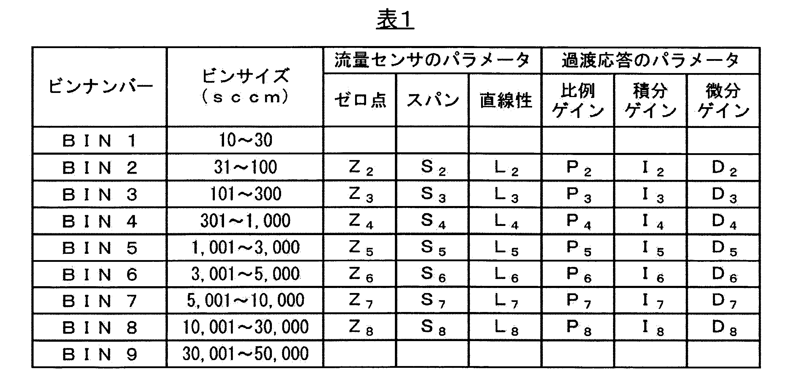
- the producer divides the rated flow range into several categories and produces products adapted to each category. Such rated flow divisions are hereinafter referred to as "bin sizes". Also, a number given for convenience to specify the bin size is hereinafter referred to as a "bin number”. Table 1 shows examples of bin numbers and bin sizes. In the example shown in Table 1, for example, a consumer who wants a mass flow controller with a rated flow rate of 2,000 sccm has a bin number of BIN 5 (that is, a rated flow rate of 1,001 to 3,000 sccm ) Purchase a mass flow controller from the manufacturer and use it.
- BIN 5 that is, a rated flow rate of 1,001 to 3,000 sccm
- the parts such as the flow path 10 through which the fluid flows, the bypass 21 and the valve body 31 may be individually designed differently for each bin size, or a plurality of similar rated flow rates Common parts for bin sizes may be used.
- adjusting the mass flow rate controller means that after assembly, the mass flow rate controller is actually flowed before shipping, and whether the mass flow rate controller satisfies the performance as the target value. is inspected, and if the performance is not satisfied as a result of the inspection, the parameters are changed until the target value is achieved. As mentioned above, mass flow controller tuning is actually done by rewriting parameters.
- Adjustment of the mass flow controller may be performed manually by an operator, or may be performed automatically according to operation by a computer program, as described in more detail below. Adjustment of mass flow controllers is performed individually for each mass flow controller before shipment after manufacture, and once adjusted parameters are not changed in principle.
- the present invention is an invention of a method for determining initial values of parameters to be first input to a mass flow controller when adjusting the parameters of the mass flow controller.
- the term "initial value” refers to the initial value of a parameter that is input to the mass flow controller for the first time when starting adjustment of the mass flow controller.
- default values were used as the initial parameters entered into the mass flow controller.
- the term "default value” refers to a value that is prepared in advance for the purpose of preventing system malfunctions (faults) that occur when no value is input in program processing that requires the input of some value. set value.
- the default values used in the prior art were fixed values and did not reflect the results of parameter adjustments.
- the initial values of the parameters according to the method of the present invention are determined according to a defined procedure based on the values of the parameters determined as a result of adjustments individually performed in the past.
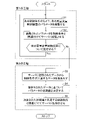
- FIG. 1 is a flow chart showing the method according to the first embodiment of the present invention.
- This method includes two steps.
- the first step comprises a first step (S1) of adjusting the parameters of a certain mass flow rate controller under certain control conditions, and storing in the server data in which the adjusted parameters and the control conditions are associated with each other. and a second step (S2) for individually executing a plurality of mass flow rate controllers, and accumulating data in the server.
- control conditions of a mass flow controller refer to various conditions that affect control of the flow rate. Specific examples of control conditions in the present invention will be described later.
- a step of storing adjusted parameters, including variations, in a server as data associated with control conditions is performed for a plurality of mass flow controllers to accumulate data in the server.
- the term "server” refers to a computer system having a storage device, preferably connected directly to the mass flow controller or via an adjustment operation terminal (e.g., personal computer, etc.) computer system. Connection between the mass flow rate controller and the server can be made through a known communication line such as a LAN cable and/or the Internet. However, a communication line connecting the mass flow controller and the server is not necessarily required. For example, when a worker manually adjusts the parameters, the worker inputs the adjusted parameters using an input device that the server itself has. By doing so, data can be accumulated in the server.
- the second step included in the method according to the first embodiment includes a third step (S3) of extracting data having a common control condition from the data accumulated in the server, and setting parameters based on the extracted data. It is a process of executing a fourth step (S4) of determining the initial values and a fifth step (S5) of storing the determined initial values of the parameters in the server in association with common control conditions.
- S3 a third step of extracting data having a common control condition from the data accumulated in the server, and setting parameters based on the extracted data. It is a process of executing a fourth step (S4) of determining the initial values and a fifth step (S5) of storing the determined initial values of the parameters in the server in association with common control conditions.
- S4 fourth step
- S5 a fifth step of storing the determined initial values of the parameters in the server in association with common control conditions.
- data with different control conditions are accumulated as data associated with the control conditions. If only data having common control conditions are extracted from the data accumulated in the server,
- Determination of the initial values of the parameters may be performed based on the extracted data, that is, using the extracted data, and the specific method of determination is not particularly limited.
- a method of determining the initial values of the parameters based on the extracted data statistical methods such as calculation of mean values and selection of medians or modes can be employed. If the determined initial values of the parameters are associated with common control conditions and stored in the server, the initial values of the parameters corresponding to the control conditions can be read from the server at any time and used as the initial values of the parameters for the next adjustment. can be used.
- the control conditions include mass flow controller type, fluid type and bin size.
- the values of the parameters determined by adjustment do not differ greatly depending on the individual mass flow controllers.
- the control conditions of the mass flow controller are different, the adjusted parameters tend to be different values than the parameters under the same control conditions. Therefore, it is important to associate with which condition among the control conditions of the mass flow controller the data is accumulated in the server.
- One control condition that has a relatively large effect on the value of the parameter is the type of mass flow controller.
- mass flow controllers include a mass flow controller equipped with a thermal flow sensor and a mass flow controller equipped with a pressure flow sensor. Even if parts other than the flow sensor, such as flow paths and flow control valves, are used in common between different types of mass flow controllers, the parameters may vary due to differences in the transient response of the flow sensor. values are often very different.
- the type of fluid to be controlled also greatly affects the parameter values. Different types of fluids have different thermal properties, viscosities, and other dynamic properties, and therefore behave differently not only in flow sensors but also in bypasses and flow control valves. For this reason, the values of the adjusted parameters also differ greatly. Furthermore, even if the type of mass flow controller and the type of fluid are the same, if the bin sizes are different, the parameter values may differ due to the difference in the Reynolds number of the fluid. As such, the values of the parameters determined by the adjustments can vary greatly depending on the various control conditions of the mass flow controller. Therefore, if the adjustment is performed using the initial values determined without considering the control conditions, it may take a long time to adjust the parameters.
- parameters having common control conditions are extracted from adjusted parameter data associated with control conditions and stored in the server, and initial values are determined based on the extracted parameters. be.
- the initial values determined in this way are different from the default values of the prior art, and are values that reflect the results of past parameter adjustments performed under the control conditions.
- control conditions including the type of mass flow controller, the type of fluid, and the bin size, which are considered to have a large influence on the parameters, are common, the effect of shortening the time required for adjustment becomes more pronounced. Any one of these elements, which are considered to have a large influence on the parameters, may be common, or two or all three of these elements may be common. The greater the number of common elements, the more pronounced the effect of the present invention.
- the method according to the present invention is such that the adjustment includes adjustment of the flow sensor, and the parameters include parameters relating to zero point, span and linearity.
- adjustment of the flow rate sensor means that the difference between the flow rate corresponding to the output signal related to the flow rate of the fluid output by the flow rate sensor incorporated in the mass flow controller and the actual flow rate is equal to or less than the target value.
- it refers to adjusting parameters that affect the output of the flow sensor.
- the operation of adjusting the flow sensor to bring the fluid flow rate sensed by the flow sensor closer to the true value is sometimes referred to as "calibrating" the mass flow controller or the flow sensor. If the flow sensor is not properly calibrated, the flow rate of the fluid on which the mass flow controller is based will contain errors and will not be able to be properly controlled. Therefore, adjusting the flow sensor is a basic and important operation.
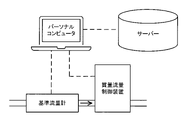
- FIG. 2 is a schematic diagram showing an example of a method for adjusting the flow rate sensor.
- the short arrows in the figure indicate the direction in which the fluid flows through the channel.
- Broken lines connecting constituent members represent routes for exchanging signals, commands, and the like between a plurality of constituent members.
- a reference flow meter that serves as a reference for measuring the flow rate and a mass flow rate controller are connected in series to allow the fluid to flow, and the output of the flow rate sensor is the reference flow rate. It is common practice to tune the flow sensor by rewriting the parameters of the flow sensor with a personal computer to match the output of the meter.
- molbloc molbloc is a US registered trademark of Fluke Corporation
- the adjusted parameters are stored in the server in association with the control conditions.
- parameters that affect the output of the flow rate sensor include, but are not limited to, zero point, span and linearity. Adjustment of the parameters relating to the zero point is performed so that the output of the flow rate sensor becomes zero when the fluid is not flowing. The parameters related to the span are adjusted so that the outputs of the flow rate sensor and the reference flow meter both indicate the full scale flow rate when the fluid of the full scale flow rate is flowed after the zero point is adjusted. Adjustment of parameters related to linearity is necessary to reduce the output of the flow sensor from the actual flow rate between the zero point and the full scale flow rate when the relationship between the output of the flow sensor and the actual flow rate deviates from the proportional relationship and non-linearity is recognized.
- the method according to the present invention is such that the adjustment includes transient response adjustment, and the parameters include parameters relating to proportional gain, integral gain and derivative gain.
- transient response adjustment refers to adjusting the transient response so that the index of the time change (transient response) of the flow rate when the set flow rate given to the mass flow controller changes is within a preset range. Adjusting parameters that affect response. Specific examples of the transient response index include, but are not limited to, the time from the start of control until the flow rate reaches 98% of the set flow rate, overshoot, hunting, and the like.
- the operation of adjusting the transient response of a mass flow controller is sometimes referred to as "tuning" the mass flow controller.
- Tuning the transient response is therefore a fundamental and important operation, similar to tuning the flow sensor.
- monitor the output of the flow sensor when the set flow rate is changed to 100%, 50%, etc. of the full scale flow rate hereinafter sometimes referred to as "step response"
- step response It is common to adjust the parameters of the mass flow controller so that the transient response index (eg, the time it takes for the flow rate to reach 98% of the set flow rate) is within a preset range.
- parameters that affect transient response include, but are not limited to, proportional gains, integral gains, and differential gains as parameters related to PID operation, which is typical feedback control.
- the flow rate control algorithm in the present invention is not limited to PID operation, and known automatic control such as feedforward control, H-infinity control, fuzzy control, and neural network control can be employed.
- the term "parameter" herein should be interpreted in its broadest sense.
- the transient response adjustment may have a large effect on the flow sensor adjustment. It is preferable to judge by Further, it is preferable to alternately repeat the adjustment of the flow rate sensor and the adjustment of the transient response a plurality of times in order to more accurately adjust the mass flow controller.
- Table 1 was determined in the preferred embodiment of the present invention as a result of tuning mass flow controllers of the same mass flow controller type and fluid type, differing only in bin size.
- 4 is a table showing examples of initial values of parameters; Table 1 lists zero point, span, and linearity parameters as parameters that affect the output of the flow sensor, and proportional gain, integral gain, and differential gain as parameters that affect transient response. A blank part in Table 1 indicates that the parameter has not been adjusted in the past under that control condition, and therefore the initial value of the parameter has not yet been determined.
- the parameters for which the detailed parameter setting as described above is particularly effective are linearity and proportional gain. This is because the flow characteristic of the flow control valve (change in flow rate with respect to opening of the valve) does not have a simple proportional relationship, but includes non-linear elements. For the same reason, these two parameters are also sensitive to different bin sizes.
- the integral gain and the derivative gain are parameters that are not easily affected by differences in full-scale divisions and bin sizes, it may be possible to use common initial values regardless of divisions and/or bin sizes.
- the initial value of the parameter for example, an average value of parameters adjusted using a plurality of (eg, 3 to 5) mass flow controllers can be used.
- the parameter adjustment of the flow sensor is the most basic adjustment in parameter adjustment, and usually the parameter adjustment of the flow sensor is performed first.
- the parameters of the flow sensor are adjusted so that the flow measured by the mass flow controller matches the flow indicated by the reference flow meter (eg, molbloc).
- each gain of the PID is adjusted so that the response time to the step input (index of the transient response obtained from the step response) is minimized.
- Any adjustment is a fine adjustment required due to individual differences in mass flow controllers. In the future, it is conceivable that it will be possible to adjust parameters based on the results of AI analyzing the big data accumulated in the server.
- the method according to the present invention ensures that the parameters initially input to the mass flow controller when adjusting the parameters are not the optimum values for the current control conditions, but can be applied over a wide range of control conditions.
- execution of the first step can be initiated by inputting predefined default values into the mass flow controller as parameters.
- the default values input at this time are not optimal values for the above control conditions, but are provisional and general-purpose default values that enable the mass flow controller to operate under a wide range of control conditions.
- temporary means a temporary value that is used only until the parameter is changed by adjustment.
- universal means that it can be commonly used for a wide range of control conditions regardless of specific control conditions.
- Such default values may be, for example, adjusted parameters in mass flow controllers with similar configurations that have been adjusted in the past and/or bin sizes for the same type of mass flow controller and the same fluid type. can be set based on parameters after adjustment in the case where .
- the invention is of a method for tuning a mass flow controller used under certain control conditions.
- the parameters of the mass flow controller are adjusted using the initial values of the parameters determined by the method of the first embodiment.
- the initial values determined by the method according to the first embodiment are different from the default values used in the prior art, and are the results of previous parameter adjustments under the control conditions in which the parameters are to be adjusted. is a value that reflects Therefore, the time from the start of adjustment of the mass flow controller to the time when the accuracy of the control operation reaches the target value can be shortened, and the adjustment can be executed quickly.
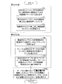
- FIG. 3 is a flowchart illustrating a method according to a second embodiment of the invention.
- the method includes a third step.
- a third step includes a sixth step (S6) of reading from the server the initial values of the parameters associated with the control conditions among the initial values of the parameters determined by the method according to the first embodiment; a seventh step (S7) of inputting the initial values of the parameters to the mass flow controller; and an eighth step (S8) of adjusting the parameters of the mass flow controller under the control conditions.
- S6 a sixth step
- S6 of reading from the server the initial values of the parameters associated with the control conditions among the initial values of the parameters determined by the method according to the first embodiment
- S7 of inputting the initial values of the parameters to the mass flow controller
- an eighth step (S8) of adjusting the parameters of the mass flow controller under the control conditions.
- the control conditions of the mass flow controller whose parameters are to be adjusted and used are determined in advance.
- the same control conditions as the parameters to be adjusted are selected. look for the initial values of the parameters adjusted under the control conditions of , and read from the server if such initial values exist.
- the read initial values are input to the mass flow controller (seventh step S7), and the parameters of the mass flow controller are adjusted again under the same control conditions as the read initial values (eighth step S8). If the desired initial value is not stored in the server, the third step cannot be executed. In such a case, before executing the third step, by executing the first step and the second step of the first embodiment under the necessary control conditions, The initial values of the parameters can be determined before performing the third step.
- the method according to the second embodiment includes a fourth step.
- a fourth step includes a ninth step (S9) of storing in the server additional data in which the parameters of the mass flow controller adjusted in the eighth step (S8) and the control conditions are associated with each other, and A tenth step (S10) of extracting data and additional data having common control conditions from the obtained data and additional data, re-determining the initial values of the parameters based on the extracted data and additional data, An eleventh step (S11) of updating the initial value to the re-determined initial value.
- the fourth step not only uses the parameters adjusted in the third step to control the mass flow rate controller, but also uses the adjusted parameters stored in the server in step S2 of the first step. This is done for the purpose of utilizing it as data for determining the initial values of the parameters used in subsequent adjustments.
- new additional data is accumulated in the server each time the mass flow controller is adjusted, so that the re-determined and updated initial values reflect the result of the latest adjustment. become. As a result, even if the determined initial value changes over time for some reason, the initial value input to the mass flow controller can correspond to the change.
- the data and additional data used to determine the initial values of the parameters in the tenth step S10 may be all the data and additional data stored in the server, or a certain number of and additional data may be selectively used.
- the former method is preferable when the initial value of the parameter to be determined repeatedly increases and decreases over time, and the latter method is preferable when the initial value increases or decreases over time.
- the method according to the second embodiment comprises initial values of the parameters read from the server and input to the mass flow controller, parameters adjusted under the control conditions and the input initial values, and
- the method further includes a twelfth step (S12) of issuing an alarm when the difference between the thresholds is exceeded.
- the twelfth step (S12) issues an alarm when the difference between the initial value input to the mass flow controller in the seventh step and the parameter adjusted in the eighth step exceeds a predetermined threshold. is a step.
- the warning issued in the twelfth step is not particularly limited as long as it can notify the operator of the occurrence of an abnormality. Specific examples of such warnings include auditory warnings such as buzzers and synthesized voices, and visual warnings such as warning lights and display indications.
- the parameter values determined by adjustment generally do not differ greatly depending on the individual mass flow controllers.
- the parameter values are not completely the same due to individual differences in the parts that make up the mass flow controller, and there are variations for each adjustment. If the variation remains within a certain range, there is no problem, but if the degree of variation is unprecedentedly large, there is a high possibility that some kind of problem has occurred in the adjustment process. Examples of causes for such a large degree of variation include, as described above, improper combination of parts constituting the mass flow controller, malfunction of parts, maladjustment, aging, and the like.
- the present invention provides a system for determining initial parameter values and a mass flow controller, as well as a method for determining initial parameter values and a method for tuning a mass flow controller. It also relates to a coordinating system.
- the present invention is a system used to determine initial values for flow control parameters that are initially input to a mass flow controller when adjusting the mass flow controller.
- the system according to the present invention includes at least one operation terminal connected to the mass flow controller and configured to adjust parameters, at least one server, and the mass flow controller, the operation terminal, and the server.
- a communication means is provided to enable data transmission and reception between the
- the operation terminal is not particularly limited as long as it can be connected to the mass flow rate control device to adjust the parameters, and as described above, it may be a computer system such as a personal computer.
- a server is also a computer system having storage devices such as hard disk drives (HDD) and solid state drives (SSD), for example.
- the communication means is not particularly limited as long as data can be exchanged between the mass flow controller, the operation terminal and the server. It consists of a series of devices (for example, a communication circuit board, etc.) that transmit and receive information.
- the system according to the present invention can be implemented by executing a predetermined command by a processing device included in the operation terminal and/or the server according to a program stored in a storage device included in the operation terminal and/or the server. is configured to perform at least the second step included in the method according to the first embodiment of . That is, in the system according to the present invention, at least the third step (S3) of extracting data having a common control condition from the data accumulated in the server, and determining the initial value of the parameter based on the extracted data.
- a fourth step (S4) and a fifth step (S5) of causing the server to store the determined initial values of the parameters in association with common control conditions are executed by the operation terminal and/or an application installed on the server. be.
- the storage device included in the operation terminal and/or server include a hard disk drive (HDD), solid state drive (SSD), memory (RAM or ROM), and the like.
- a specific example of a processing device included in the operation terminal and/or the server is, for example, a so-called central processing unit (CPU).
- the program for causing the processing device to execute the second step may be stored in a storage device included in either the operation terminal or the server, or distributed to storage devices included in both the operation terminal and the server. may be stored as Further, each of the above steps may be executed by a processing device included in either the operation terminal or the server, or may be executed by distributed processing by processing devices included in both the operation terminal and the server.
- Data can be stored in the server by the operator entering the adjusted parameters using the server's own input device.
- the data can be accumulated in the server by having the operator input the adjusted parameters using the input device of the operation terminal and transmitting the parameters to the server via the communication means.
- the adjusted parameters are automatically stored in the server by the application (that is, by the processing unit executing predetermined instructions according to the program).
- the processor executes a predetermined instruction according to the program. is configured to execute the second step. That is, in this system, there is a step of individually executing the second step of storing data in which the adjusted parameters and the control conditions are associated with each other in the server for the plurality of mass flow controllers, and accumulating the data in the server. It is executed by an application installed in the operation terminal and/or server.
- the application may start executing the second step when the worker performs some operation (eg, inputting a predetermined command or clicking an object such as a button provided in the user interface).
- the determination as to whether the accuracy of flow control by the mass flow controller has reached a predetermined target value can also be made automatically by the application (i.e., by the processor executing predetermined instructions according to a program). should be implemented.
- a system according to the present invention comprises means for receiving signals from the mass flow controller necessary for detecting an indication of changes in the flow rate over time (transient response) when the set flow rate applied to the flow controller changes, and
- the program must be provided with instructions for executing the algorithms necessary to make the determination.
- the first step included in the method according to the present invention is also automatically executed by the application (that is, by the processing device executing predetermined instructions according to the program). is desirable.
- the system according to the present invention is configured such that in a first step, the parameter is increased or decreased by a predetermined amount by executing a predetermined instruction according to the program by the processing device. That is, according to this system, in a first step, under certain control conditions, the parameters of the mass flow controller are automatically set by the application (i.e., by the execution of predetermined instructions by the processor according to the program). adjusted.
- the degree to which the system increases or decreases the parameter in the first step may be a predetermined fixed value for each parameter, or the flow rate It may be a value that increases or decreases according to the degree of dissociation from the target value of control accuracy.
- the program may be configured such that the greater the degree of dissociation from the target value of the accuracy of flow control, the greater the increase or decrease of the parameter.
- the invention is of a system for regulating mass flow controllers used under certain control conditions.
- the parameters of the mass flow controller are adjusted using the initial values of the parameters determined by the method of the first embodiment.
- the initial values determined by the method according to the first embodiment are different from the default values used in the prior art, and are the values of parameter adjustments performed in the past under the control conditions in which the parameters are to be adjusted.
- the value reflects the result. Therefore, the time from the start of adjustment of the mass flow controller to the time when the accuracy of the control operation reaches the target value can be shortened, and the parameter adjustment can be quickly completed.
- the system according to the fourth embodiment executes at least the sixth step and the seventh step included in the method according to the second embodiment of the present invention by the processing device executing a predetermined instruction according to the program.
- the processing device executing a predetermined instruction according to the program.
- the eighth step included in the method according to the present invention can also be automatically executed by the application (that is, by the processing device executing predetermined instructions according to the program). desirable. Therefore, in a preferred embodiment, in the eighth step, the system according to the present invention is configured to increase or decrease the parameter by a predetermined amount by executing a predetermined instruction according to the program by the processor. .
- the degree to which the system increases or decreases the parameter in the eighth step may be a fixed value predetermined for each parameter, or the flow rate It may be a value that increases or decreases according to the degree of dissociation from the target value of control accuracy.
- the program may be configured such that the greater the degree of dissociation from the target value of the accuracy of flow control, the greater the increase or decrease of the parameter.
- the system according to the fourth embodiment executes the fourth step included in the above-described method according to the second preferred embodiment by having the processing device execute predetermined instructions according to the program.
- the system executes the fourth step included in the above-described method according to the second preferred embodiment by having the processing device execute predetermined instructions according to the program.
- the eleventh step of updating the initial value to the re-determined initial value is automatically performed by the application (ie, by the processing unit executing predetermined instructions according to the program). Therefore, according to this system, the initial values of the parameters can be updated more efficiently by automatically executing the fourth step.
- the system according to the fourth embodiment executes the twelfth step included in the method according to the second preferred embodiment described above by the processing device executing predetermined instructions according to the program. is configured as That is, this system issues an alarm when the difference between the initial value of the parameter read from the server and input to the mass flow controller and the parameter adjusted under the control conditions and the input initial value exceeds the threshold. configured to emit
Landscapes
- Physics & Mathematics (AREA)
- General Physics & Mathematics (AREA)
- Engineering & Computer Science (AREA)
- Automation & Control Theory (AREA)
- Fluid Mechanics (AREA)
- Human Computer Interaction (AREA)
- Flow Control (AREA)
Abstract
Description
第1の工程:ある制御条件のもとで、ある質量流量制御装置のパラメータを調整する第1ステップと、調整されたパラメータと制御条件とが関連付けられてなるデータをサーバに記憶させる第2ステップと、を複数の質量流量制御装置について個別に実行して、サーバにデータを蓄積する。
第2の工程:サーバに蓄積されたデータから制御条件が共通するデータを抜き出す第3ステップと、抜き出されたデータに基づいて共通する制御条件に対応するパラメータの初期値を決定する第4ステップと、決定されたパラメータの初期値を、共通する制御条件と関連付けてサーバに記憶させる第5ステップと、を実行する。
本発明に係る方法によって決定されたパラメータの初期値は、質量流量制御装置の過去の調整の結果が反映された初期値となる。
第6ステップ:本発明に係る方法によって決定されたパラメータの初期値のうち、制御条件と関連付けられたパラメータの初期値をサーバから読み出す。
第7ステップ:読み出されたパラメータの初期値を質量流量制御装置に入力する。
第8ステップ:制御条件のもとで質量流量制御装置のパラメータを調整する。
この方法によれば、質量流量制御装置の過去の調整の結果が反映されたパラメータの初期値から質量流量制御装置の調整をスタートすることができる。
図4は、質量流量制御装置の構成の例を示す模式図である。図4は、質量流量制御装置の構成を概念的に示すものであって、これらの質量流量制御装置及びそれらを構成する部品の形状、構造及び組合せを具体的に示すものではないことに留意すべきである。
本明細書において、質量流量制御装置が制御することができる流体の流量の最大値を以下「定格流量」又は「フルスケール流量」という。需要者が質量流量制御装置に求める定格流量は、標準状態の窒素ガス換算で、例えば、10標準立方センチメートル毎分(以下「sccm」という。)から50,000sccmまでのように、極めて広範囲に及ぶ。図4に例示される質量流量制御装置1において、定格流量は、流体が直接接する流路10、バイパス21及び弁体31の断面積及び形状に大きく依存する。これらの部品における流体が流れる部分の断面積が大きければ大きいほど、質量流量制御装置1が制御することができる流体の流量の最大値が大きくなる。大きな定格流量用に設計された質量流量制御装置を用いて小さな流量を制御すると、流量制御の精度が低くなる。逆に、小さな定格流量を制御することができるように小さい断面積を有する部品で構成された質量流量制御装置を用いて大きな流量の流体を供給することは、物理的に不可能である。したがって、流体が流れる流路10、バイパス21及び弁体31などの部品は、定格流量の大きさに適合するように個別に設計する必要がある。
本明細書において「パラメータ」とは、質量流量制御装置が流量制御アルゴリズムを実行するに際して、制御の内容を決定することを目的として入力される変数をいう。質量流量制御装置において使用されるパラメータの種類は1種類であってもよいし、2種類以上であってもよい。本発明におけるパラメータの具体例については後述する。本明細書において「質量流量制御装置を調整する」とは、組み立て後、出荷前の質量流量制御装置に実際に流体を流して、質量流量制御装置が目標値どおりの性能を満足しているかどうかを検査し、検査の結果性能を満足していなければ、目標値を達成するまでパラメータを変更することをいう。前述のとおり、質量流量制御装置の調整は実際にはパラメータの書き換えによって行われる。すなわち、質量流量制御装置に実際に流体を流して制御動作を検査する作業と、検査された制御動作に基づいてパラメータを書き換える作業とを交互に繰り返しながら、制御動作の精度が目標値に達するまで行われる。質量流量制御装置の調整は、作業者が手動によって行ってもよく、或いは、詳しくは後述するように、コンピュータプログラムによる操作に従って自動的に実行してもよい。質量流量制御装置の調整は、製造後、出荷前の質量流量制御装置の1台ごとに個別に行われ、一旦調整されたパラメータは原則として変更されない。
第1の実施形態において、本発明は、質量流量制御装置のパラメータを調整するときに質量流量制御装置に最初に入力するパラメータの初期値を決定する方法の発明である。本明細書において「初期値」とは、質量流量制御装置の調整を開始するにあたって質量流量制御装置に初めて入力するパラメータの初期値(initial value)をいう。従来技術においては、質量流量制御装置に最初に入力するパラメータとして、デフォルト値(default value)を用いていた。本明細書において「デフォルト値」とは、何らかの値の入力が必要なプログラム処理において、値が未入力の場合に生じるシステムの誤作動(fault)を未然に防止することを目的として、予め準備された設定値をいう。従来技術において用いられていたデフォルト値は、固定された値であって、パラメータの調整の結果が反映されることはなかった。これに対し、本発明の方法に係るパラメータの初期値は、過去に個別に実行された調整の結果として決定されたパラメータの値に基づいて、定められた手順に従って決定されるものである。
第2の実施形態において、本発明は、ある制御条件で使用される質量流量制御装置を調整する方法の発明である。この方法においては、第1の実施形態に係る方法によって決定されたパラメータの初期値を使用して質量流量制御装置のパラメータが調整される。前述のとおり、第1の実施形態に係る方法によって決定された初期値は、従来技術において用いられるデフォルト値とは異なり、パラメータを調整しようとする制御条件において過去に実行されたパラメータの調整の結果が反映された値となっている。このため、質量流量制御装置の調整の開始から制御動作の精度が目標値に達するまでの時間が短縮され、調整を迅速に実行することができる。
本明細書の冒頭において述べたように、本発明は、パラメータの初期値を決定する方法及び質量流量制御装置を調整する方法のみならず、パラメータの初期値を決定するシステム及び質量流量制御装置を調整するシステムにも関する。
第4の実施形態において、本発明は、ある制御条件で使用される質量流量制御装置を調整するシステムの発明である。このシステムにおいては、第1の実施形態に係る方法によって決定されたパラメータの初期値を使用して質量流量制御装置のパラメータが調整される。前述したように、第1の実施形態に係る方法によって決定された初期値は、従来技術において用いられるデフォルト値とは異なり、パラメータを調整しようとする制御条件において過去に実行されたパラメータの調整の結果が反映された値となっている。このため、質量流量制御装置の調整の開始から制御動作の精度が目標値に達するまでの時間が短縮され、パラメータの調整を迅速に完了することができる。
10 流路
11 入口
12 出口
20 流量センサ
21 バイパス
22 センサチューブ
23 電熱ワイヤ
30 流量制御弁
31 弁体
32 駆動機構
40 制御部
Claims (15)
- 質量流量制御装置を調整するときに前記質量流量制御装置に最初に入力される流量制御に関するパラメータの初期値を決定する方法であって、
ある制御条件のもとで、ある質量流量制御装置の前記パラメータを調整する第1ステップと、
調整された前記パラメータと前記制御条件とが関連付けられてなるデータをサーバに記憶させる第2ステップと、
を複数の質量流量制御装置について個別に実行して、前記サーバに前記データを蓄積する第1の工程と、
前記サーバに蓄積された前記データから前記制御条件が共通する前記データを抜き出す第3ステップと、
抜き出された前記データに基づいて共通する前記制御条件に対応する前記パラメータの前記初期値を決定する第4ステップと、
決定された前記パラメータの前記初期値を、共通する前記制御条件と関連付けて前記サーバに記憶させる第5ステップと、
を実行する第2の工程と、
を含む方法。 - 前記制御条件が、質量流量制御装置の種類、流体の種類及びビンサイズを含む、
請求項1に記載の方法。 - 前記質量流量制御装置の前記調整が、流量センサの調整を含み、
決定された前記パラメータの前記初期値が、ゼロ点、スパン及び直線性に関するパラメータの初期値を含む、
請求項1又は2に記載の方法。 - 前記質量流量制御装置の前記調整が、過渡応答の調整を含み、
決定された前記パラメータの前記初期値が、比例ゲイン、積分ゲイン及び微分ゲインに関するパラメータの初期値を含む、
請求項1から3までのいずれかに記載の方法。 - 前記第1ステップにおいて、前記パラメータを調整するときに前記質量流量制御装置に最初に入力される前記パラメータが、前記制御条件について最適な値ではないが、幅広い制御条件のもとで前記質量流量制御装置を動作させることができる暫定的かつ汎用的なデフォルト値である、
請求項1から4までのいずれかに記載の方法。 - ある制御条件で使用される質量流量制御装置を調整する方法であって、
請求項1から5までのいずれかに記載の方法によって決定された前記パラメータの前記初期値のうち、前記制御条件と関連付けられた前記パラメータの前記初期値を前記サーバから読み出す第6ステップと、
読み出された前記パラメータの前記初期値を前記質量流量制御装置に入力する第7ステップと、
前記制御条件のもとで前記質量流量制御装置の前記パラメータを調整する第8ステップと、
を実行する第3の工程、
を含む方法。 - 前記第8ステップにおいて調整された前記質量流量制御装置の前記パラメータと前記制御条件とが関連付けられてなる追加データを前記サーバに記憶させる第9ステップと、
前記サーバに記憶された前記データ及び前記追加データから前記制御条件が共通する前記データ及び前記追加データを抜き出す第10ステップと、
抜き出された前記データ及び前記追加データに基づいてパラメータの初期値を再決定し、前記サーバに記憶された前記初期値を再決定された前記初期値に更新する第11ステップと、
を実行する第4の工程、
をさらに含む請求項6に記載の方法。 - 前記第7ステップにおいて質量流量制御装置に入力された前記初期値と前記第8ステップにおいて調整された前記パラメータとの差が所定の閾値を超えたときに警報を発する第12ステップ、
をさらに含む請求項6又は7のいずれかに記載の方法。 - 質量流量制御装置を調整するときに前記質量流量制御装置に最初に入力される流量制御に関するパラメータの初期値を決定するために使用されるシステムであって、
前記質量流量制御装置に接続されて前記パラメータを調整することができるように構成された少なくとも1台の操作端末、少なくとも1台のサーバ、及び前記質量流量制御装置と前記操作端末と前記サーバとの間におけるデータの授受を可能とする通信手段を備え、
前記操作端末及び/又は前記サーバが備える記憶装置に格納されたプログラムに従い、前記操作端末及び/又は前記サーバが備える処理装置が所定の命令を実行することにより、請求項1から5までのいずれかに記載の方法に含まれる少なくとも前記第2の工程を実行するように構成されたシステム。 - 前記第1ステップの実行により前記質量流量制御装置による流量制御の精度が所定の目標値に達したら前記プログラムに従って前記処理装置が所定の命令を実行することにより前記第2ステップを実行するように構成された、
請求項9に記載のシステム。 - 前記第1ステップにおいて前記プログラムに従って前記処理装置が所定の命令を実行することにより前記パラメータを所定の量だけ増加又は減少させるように構成された、
請求項9又は10に記載のシステム。 - 前記プログラムに従って前記処理装置が所定の命令を実行することにより請求項6に記載の方法に含まれる少なくとも前記第6ステップ及び前記第7ステップを実行するように構成された、
請求項9から11までのいずれかに記載のシステム。 - 前記第8ステップにおいて前記プログラムに従って前記処理装置が所定の命令を実行することにより前記パラメータを所定の量だけ増加又は減少させるように構成された、
請求項12に記載のシステム。 - 前記プログラムに従って前記処理装置が所定の命令を実行することにより請求項7に記載の方法に含まれる前記第4の工程を実行するように構成された、
請求項12又は13に記載のシステム。 - 前記プログラムに従って前記処理装置が所定の命令を実行することにより請求項8に記載の方法に含まれる前記第12ステップを実行するように構成された、
請求項11から14までのいずれかに記載のシステム。
Priority Applications (4)
| Application Number | Priority Date | Filing Date | Title |
|---|---|---|---|
| US18/547,758 US20240126309A1 (en) | 2021-03-24 | 2022-02-14 | Method and system for determining an initial value of at least one parameter and method and system for adjusting a mass flow controller |
| JP2023508771A JP7840313B2 (ja) | 2021-03-24 | 2022-02-14 | パラメータの初期値を決定する方法及びシステム並びに質量流量制御装置を調整する方法及びシステム |
| CN202280023596.XA CN117043705B (zh) | 2021-03-24 | 2022-02-14 | 决定参数的初始值的方法及系统、以及调整质量流量控制装置的方法及系统 |
| KR1020237032211A KR20230160826A (ko) | 2021-03-24 | 2022-02-14 | 파라미터의 초깃값을 결정하는 방법 및 시스템 그리고 질량 유량 제어 장치를 조정하는 방법 및 시스템 |
Applications Claiming Priority (2)
| Application Number | Priority Date | Filing Date | Title |
|---|---|---|---|
| JP2021050631 | 2021-03-24 | ||
| JP2021-050631 | 2021-03-24 |
Publications (1)
| Publication Number | Publication Date |
|---|---|
| WO2022201963A1 true WO2022201963A1 (ja) | 2022-09-29 |
Family
ID=83395543
Family Applications (1)
| Application Number | Title | Priority Date | Filing Date |
|---|---|---|---|
| PCT/JP2022/005733 Ceased WO2022201963A1 (ja) | 2021-03-24 | 2022-02-14 | パラメータの初期値を決定する方法及びシステム並びに質量流量制御装置を調整する方法及びシステム |
Country Status (5)
| Country | Link |
|---|---|
| US (1) | US20240126309A1 (ja) |
| JP (1) | JP7840313B2 (ja) |
| KR (1) | KR20230160826A (ja) |
| CN (1) | CN117043705B (ja) |
| WO (1) | WO2022201963A1 (ja) |
Citations (3)
| Publication number | Priority date | Publication date | Assignee | Title |
|---|---|---|---|---|
| JP2005531069A (ja) * | 2002-06-24 | 2005-10-13 | エム ケー エス インストルメンツ インコーポレーテッド | 圧力の揺らぎに鈍感な質量流量制御のための装置及び方法 |
| JP2008039513A (ja) * | 2006-08-03 | 2008-02-21 | Hitachi Metals Ltd | 質量流量制御装置の流量制御補正方法 |
| JP2016025503A (ja) * | 2014-07-22 | 2016-02-08 | コニカミノルタ株式会社 | 画像形成システム |
Family Cites Families (13)
| Publication number | Priority date | Publication date | Assignee | Title |
|---|---|---|---|---|
| JPH07263350A (ja) | 1994-03-18 | 1995-10-13 | Fujitsu Ltd | 半導体製造方法 |
| US5865205A (en) * | 1997-04-17 | 1999-02-02 | Applied Materials, Inc. | Dynamic gas flow controller |
| KR20040024854A (ko) * | 2001-04-24 | 2004-03-22 | 셀레리티 그룹 아이엔씨 | 질량유량 제어장치를 위한 시스템 및 방법 |
| DE10392770B3 (de) * | 2002-06-24 | 2013-08-01 | Mks Instruments Inc. | Massenstrom-Sensor und Verfahren zur Druckschwankungs-unabhaengigen Massenstroemungs-Steuerung |
| US7136767B2 (en) * | 2002-06-24 | 2006-11-14 | Mks Instruments, Inc. | Apparatus and method for calibration of mass flow controller |
| US6810308B2 (en) * | 2002-06-24 | 2004-10-26 | Mks Instruments, Inc. | Apparatus and method for mass flow controller with network access to diagnostics |
| US8915262B2 (en) * | 2011-08-09 | 2014-12-23 | Hitachi Metals, Ltd. | Mass flow controller algorithm with adaptive valve start position |
| JP5969869B2 (ja) | 2012-09-14 | 2016-08-17 | 株式会社堀場エステック | 流量制御装置及び流量制御装置用プログラム |
| JP5696171B2 (ja) * | 2013-03-14 | 2015-04-08 | 株式会社東芝 | 制御パラメータ調整方法、制御パラメータ調整システム及び制御パラメータ設定装置 |
| JP6520945B2 (ja) * | 2014-07-15 | 2019-05-29 | 日立金属株式会社 | 流体の流量を制御する方法、当該方法を実行する質量流量制御装置及び当該質量流量制御装置を用いた質量流量制御システム |
| CN107305855B (zh) * | 2016-04-19 | 2021-05-07 | 株式会社国际电气 | 衬底处理装置、装置管理控制器及装置管理方法 |
| JP6670791B2 (ja) * | 2017-03-30 | 2020-03-25 | 東京エレクトロン株式会社 | 流量制御器を検査する方法及び被処理体を処理する方法 |
| US11073845B2 (en) | 2019-08-26 | 2021-07-27 | Hitachi Metals, Ltd. | Parasitic flow correction method and apparatus |
-
2022
- 2022-02-14 CN CN202280023596.XA patent/CN117043705B/zh active Active
- 2022-02-14 JP JP2023508771A patent/JP7840313B2/ja active Active
- 2022-02-14 US US18/547,758 patent/US20240126309A1/en active Pending
- 2022-02-14 WO PCT/JP2022/005733 patent/WO2022201963A1/ja not_active Ceased
- 2022-02-14 KR KR1020237032211A patent/KR20230160826A/ko active Pending
Patent Citations (3)
| Publication number | Priority date | Publication date | Assignee | Title |
|---|---|---|---|---|
| JP2005531069A (ja) * | 2002-06-24 | 2005-10-13 | エム ケー エス インストルメンツ インコーポレーテッド | 圧力の揺らぎに鈍感な質量流量制御のための装置及び方法 |
| JP2008039513A (ja) * | 2006-08-03 | 2008-02-21 | Hitachi Metals Ltd | 質量流量制御装置の流量制御補正方法 |
| JP2016025503A (ja) * | 2014-07-22 | 2016-02-08 | コニカミノルタ株式会社 | 画像形成システム |
Also Published As
| Publication number | Publication date |
|---|---|
| JPWO2022201963A1 (ja) | 2022-09-29 |
| KR20230160826A (ko) | 2023-11-24 |
| JP7840313B2 (ja) | 2026-04-03 |
| CN117043705B (zh) | 2026-07-31 |
| CN117043705A (zh) | 2023-11-10 |
| US20240126309A1 (en) | 2024-04-18 |
Similar Documents
| Publication | Publication Date | Title |
|---|---|---|
| US8015995B2 (en) | System and method for flow monitoring and control | |
| US7610117B2 (en) | System and method for flow monitoring and control | |
| EP2089679B1 (en) | Controller gain scheduling for mass flow controllers | |
| JP6871636B2 (ja) | 圧力式流量制御装置及び流量自己診断方法 | |
| US20150276449A1 (en) | Mass flow meter and mass flow controller using the same | |
| US6138708A (en) | Mass flow controller having automatic pressure compensator | |
| US9846074B2 (en) | System for and method of monitoring flow through mass flow controllers in real time | |
| EP2901227B1 (en) | Method and apparatus for self verification of pressure based mass flow controllers | |
| US10048105B2 (en) | System and method for providing a self validating mass flow controller and mass flow meter | |
| CN101408276B (zh) | 流量检定系统和流量检定方法 | |
| KR102519482B1 (ko) | 가스 유량 감시 방법 및 가스 유량 감시 장치 | |
| US9471066B2 (en) | System for and method of providing pressure insensitive self verifying mass flow controller | |
| EP2246766A1 (en) | Flow measurement module and method | |
| CN101737169A (zh) | 用于燃气涡轮的燃料控制系统和前馈控制方法 | |
| AU2002361817A1 (en) | Flow measurement module and method | |
| JP6484248B2 (ja) | 圧力無反応性自己検証質量流量制御装置を提供するシステムおよび方法 | |
| US10302476B2 (en) | Flow rate control device | |
| JP7531881B2 (ja) | 流量制御システム、流量制御システムの制御方法、流量制御システムの制御プログラム | |
| US20020157448A1 (en) | Flowmeter calibration apparatus | |
| WO2025038383A1 (en) | Method and apparatus for automatic self calibration of mass flow controller | |
| JPH11294631A (ja) | 流量コントローラ | |
| JP7840313B2 (ja) | パラメータの初期値を決定する方法及びシステム並びに質量流量制御装置を調整する方法及びシステム | |
| KR102693467B1 (ko) | 유체 장치 및 유체 장치용 프로그램 | |
| JP7309372B2 (ja) | 燃焼関連情報提供制御装置、燃焼関連情報提供制御プログラム | |
| JPH06104155A (ja) | 半導体製造プロセスにおける中間制御装置 |
Legal Events
| Date | Code | Title | Description |
|---|---|---|---|
| 121 | Ep: the epo has been informed by wipo that ep was designated in this application |
Ref document number: 22774763 Country of ref document: EP Kind code of ref document: A1 |
|
| ENP | Entry into the national phase |
Ref document number: 2023508771 Country of ref document: JP Kind code of ref document: A |
|
| WWE | Wipo information: entry into national phase |
Ref document number: 18547758 Country of ref document: US |
|
| WWE | Wipo information: entry into national phase |
Ref document number: 202280023596.X Country of ref document: CN |
|
| NENP | Non-entry into the national phase |
Ref country code: DE |
|
| 122 | Ep: pct application non-entry in european phase |
Ref document number: 22774763 Country of ref document: EP Kind code of ref document: A1 |