WO2022201850A1 - 工作機械 - Google Patents
工作機械 Download PDFInfo
- Publication number
- WO2022201850A1 WO2022201850A1 PCT/JP2022/003265 JP2022003265W WO2022201850A1 WO 2022201850 A1 WO2022201850 A1 WO 2022201850A1 JP 2022003265 W JP2022003265 W JP 2022003265W WO 2022201850 A1 WO2022201850 A1 WO 2022201850A1
- Authority
- WO
- WIPO (PCT)
- Prior art keywords
- identifier
- cover
- machine tool
- state
- door portion
- Prior art date
- Legal status (The legal status is an assumption and is not a legal conclusion. Google has not performed a legal analysis and makes no representation as to the accuracy of the status listed.)
- Ceased
Links
Images








Classifications
-
- B—PERFORMING OPERATIONS; TRANSPORTING
- B23—MACHINE TOOLS; METAL-WORKING NOT OTHERWISE PROVIDED FOR
- B23Q—DETAILS, COMPONENTS, OR ACCESSORIES FOR MACHINE TOOLS, e.g. ARRANGEMENTS FOR COPYING OR CONTROLLING; MACHINE TOOLS IN GENERAL CHARACTERISED BY THE CONSTRUCTION OF PARTICULAR DETAILS OR COMPONENTS; COMBINATIONS OR ASSOCIATIONS OF METAL-WORKING MACHINES, NOT DIRECTED TO A PARTICULAR RESULT
- B23Q11/00—Accessories fitted to machine tools for keeping tools or parts of the machine in good working condition or for cooling work; Safety devices specially combined with or arranged in, or specially adapted for use in connection with, machine tools
-
- B—PERFORMING OPERATIONS; TRANSPORTING
- B23—MACHINE TOOLS; METAL-WORKING NOT OTHERWISE PROVIDED FOR
- B23Q—DETAILS, COMPONENTS, OR ACCESSORIES FOR MACHINE TOOLS, e.g. ARRANGEMENTS FOR COPYING OR CONTROLLING; MACHINE TOOLS IN GENERAL CHARACTERISED BY THE CONSTRUCTION OF PARTICULAR DETAILS OR COMPONENTS; COMBINATIONS OR ASSOCIATIONS OF METAL-WORKING MACHINES, NOT DIRECTED TO A PARTICULAR RESULT
- B23Q11/00—Accessories fitted to machine tools for keeping tools or parts of the machine in good working condition or for cooling work; Safety devices specially combined with or arranged in, or specially adapted for use in connection with, machine tools
- B23Q11/08—Protective coverings for parts of machine tools; Splash guards
-
- B—PERFORMING OPERATIONS; TRANSPORTING
- B23—MACHINE TOOLS; METAL-WORKING NOT OTHERWISE PROVIDED FOR
- B23Q—DETAILS, COMPONENTS, OR ACCESSORIES FOR MACHINE TOOLS, e.g. ARRANGEMENTS FOR COPYING OR CONTROLLING; MACHINE TOOLS IN GENERAL CHARACTERISED BY THE CONSTRUCTION OF PARTICULAR DETAILS OR COMPONENTS; COMBINATIONS OR ASSOCIATIONS OF METAL-WORKING MACHINES, NOT DIRECTED TO A PARTICULAR RESULT
- B23Q17/00—Arrangements for observing, indicating or measuring on machine tools
-
- B—PERFORMING OPERATIONS; TRANSPORTING
- B23—MACHINE TOOLS; METAL-WORKING NOT OTHERWISE PROVIDED FOR
- B23Q—DETAILS, COMPONENTS, OR ACCESSORIES FOR MACHINE TOOLS, e.g. ARRANGEMENTS FOR COPYING OR CONTROLLING; MACHINE TOOLS IN GENERAL CHARACTERISED BY THE CONSTRUCTION OF PARTICULAR DETAILS OR COMPONENTS; COMBINATIONS OR ASSOCIATIONS OF METAL-WORKING MACHINES, NOT DIRECTED TO A PARTICULAR RESULT
- B23Q17/00—Arrangements for observing, indicating or measuring on machine tools
- B23Q17/24—Arrangements for observing, indicating or measuring on machine tools using optics or electromagnetic waves
-
- B—PERFORMING OPERATIONS; TRANSPORTING
- B23—MACHINE TOOLS; METAL-WORKING NOT OTHERWISE PROVIDED FOR
- B23Q—DETAILS, COMPONENTS, OR ACCESSORIES FOR MACHINE TOOLS, e.g. ARRANGEMENTS FOR COPYING OR CONTROLLING; MACHINE TOOLS IN GENERAL CHARACTERISED BY THE CONSTRUCTION OF PARTICULAR DETAILS OR COMPONENTS; COMBINATIONS OR ASSOCIATIONS OF METAL-WORKING MACHINES, NOT DIRECTED TO A PARTICULAR RESULT
- B23Q3/00—Devices holding, supporting, or positioning work or tools, of a kind normally removable from the machine
- B23Q3/155—Arrangements for automatic insertion or removal of tools, e.g. combined with manual handling
- B23Q3/157—Arrangements for automatic insertion or removal of tools, e.g. combined with manual handling of rotary tools
Definitions
- This invention relates to machine tools.
- Patent Document 1 discloses a machine tool having an identification figure for posture correction arranged in a machining area and a camera for capturing an image of the identification figure.
- a production system includes a robot that performs work with a robot.
- a transfer mechanism such as a robot is positioned with respect to the machine tool by placing an identification figure on the machine tool and taking an image of the identification figure with a camera.
- the identification figure is soiled by foreign matter such as chips, coolant, or mist generated in the machining area, it becomes difficult to properly position the transfer mechanism with respect to the machine tool.
- An object of the present invention is to solve the above problems, and to provide a machine tool in which positioning of the transfer mechanism is properly performed.
- a machine tool is a machine tool in which a transfer mechanism having a camera is used to transfer an object to be transferred between an internal space and an external space outside the internal space.
- the machine tool includes a movable cover operable between a first state separating the inner space and the outer space and a second state opening the inner space toward the outer space, and a fixed cover provided in the inner space.
- a cover and an identifier supported by a first cover which is either one of a movable cover and a fixed cover, in the interior space and imaged by a camera for positioning the transport mechanism with respect to the machine tool.
- the identifier When the movable cover is in the first state, the identifier is positioned to face the second cover, which is the other of the movable cover and the fixed cover, and when the movable cover is in the second state. is positioned further away from the second cover than in the first state.
- the identifier when the movable cover is in the first state and the inner space and the outer space are separated by the movable cover, the identifier is positioned facing the second cover. As a result, it is possible to suppress contamination of the identifier by foreign matter such as coolant, chips, or mist in the internal space.
- the identifier when the movable cover is in the second state and the interior space is open to the exterior space, the identifier is positioned farther from the second cover than in the first state, thereby keeping it clean.
- the identifier can be imaged by a camera. As a result, the transfer mechanism can be properly positioned with respect to the machine tool.
- the internal space is a machining area in which workpieces are machined, or a magazine area in which a plurality of tools are stored.
- the movable cover is a door portion provided on a cover body that partitions and forms a processing area or an area inside the magazine.
- the machine tool configured in this way, it is possible to prevent the identifier from being contaminated by coolant, chips, mist, etc. in the machining area or the area inside the magazine.
- the movable cover is a door portion provided on the cover body that partitions and forms the processing area or the magazine area, the first state and the second state can be obtained as the door portion is opened and closed. can.
- the machine tool is provided so as to separate the space around the identifier from the internal space when the movable cover is in the first state, and prevents foreign objects from entering the identifier from the internal space.
- An intrusion prevention mechanism is further provided.
- the machine tool further includes an air supply mechanism that supplies air to the space around the identifier.
- the identifier is a graphic.
- the first cover has a planar shape and includes a planar portion to which a graphic is attached.
- the figure can be kept planar by attaching the figure to the planar portion having a planar shape. Thereby, the positioning of the transfer mechanism with respect to the machine tool can be performed more appropriately.
- FIG. 1 is a top view schematically showing a production system equipped with a machine tool according to Embodiment 1 of the present invention
- FIG. FIG. 2 is a perspective view showing a transport mechanism used in the production system in FIG. 1
- FIG. 2 is a front view showing the machine tool in FIG. 1
- It is a front view showing an identifier.
- FIG. 10 is a diagram showing an example of an identifier image captured by a camera when a work is conveyed
- FIG. 4 is a top view showing the machine tool during work transfer
- FIG. 4 is a front view showing the machine tool during work transfer
- FIG. 4 is a top view showing the machine tool during work machining
- FIG. 4 is a front view showing the machine tool during work machining
- FIG. 4 is a front view showing the machine tool during work machining
- FIG. 10 is a diagram showing an example of an identifier image captured by a camera when a work is conveyed
- FIG. 4 is a top view showing the machine tool
- FIG. 4 is a perspective view showing an identifier attachment structure within a processing area; It is a side view in the processing area which shows the modification of a foreign material invasion prevention mechanism.
- FIG. 10 is a top view showing a machine tool (during work transfer) according to Embodiment 2 of the present invention;
- FIG. 10 is a front view showing a machine tool (at the time of conveying a work) according to Embodiment 2 of the present invention;
- FIG. 10 is a top view showing a machine tool (during workpiece machining) according to Embodiment 2 of the present invention;
- FIG. 8 is a front view showing a machine tool (during work machining) according to Embodiment 2 of the present invention;
- FIG. 11 is a top view schematically showing a production system equipped with a machine tool according to Embodiment 3 of the present invention;
- FIG. 1 is a top view schematically showing a production system equipped with machine tools according to Embodiment 1 of the present invention.
- 2 is a perspective view showing a transport mechanism used in the production system in FIG. 1.
- FIG. 1 is a top view schematically showing a production system equipped with machine tools according to Embodiment 1 of the present invention.
- the production system has a machine tool 10, a material stocker 122 and a product stocker 121, a transport mechanism 120, and a controller 140 for controlling the transport mechanism 120.
- the material stocker 122 is a device that is arranged on the left side of the machine tool 10 in FIG.
- the product stocker 121 is arranged on the right side of the machine tool 10 in FIG. 1 and is a device that stocks a plurality of products machined by the machine tool 10 or semi-finished products (machined works).
- the transport mechanism 120 transports a workpiece as a transport object to the machine tool 10 .
- the transport mechanism 120 has an automatic guided vehicle 135 and a robot 125 .
- the robot 125 is mounted on an unmanned guided vehicle 135.
- the robot 125 is mounted on a mounting surface 136 that is the upper surface of the automatic guided vehicle 135 .
- the automatic guided vehicle 135 is provided with an operation panel 137 that can be carried by an operator.
- the operation panel 137 has an input/output unit for inputting/outputting data, an operation unit for manually operating the automatic guided vehicle 135 and the robot 125, and a screen display.
- the automatic guided vehicle 135 has a sensor (for example, a distance measurement sensor using laser light) that can recognize its own position in the factory.
- the unmanned guided vehicle 135 is configured to run without a track in the factory including the area where the machine tool 10, the material stocker 122 and the product stocker 121 are arranged based on the control by the control device 140.
- the robot 125 is an articulated robot having a first arm 126, a second arm 127 and a third arm 128.
- the robot 125 further has a hand 129 as an end effector.
- a hand 129 is attached to the tip of the third arm 128 .
- the transport mechanism 120 (robot 125 ) further has a camera 131 .
- Camera 131 is a stereo camera.
- a camera 131 is attached to the third arm 128 via an attachment bar 130 .
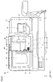
- FIG. 3 is a front view showing the machine tool in FIG.
- machine tool 10 is a lathe that performs work machining by bringing the tool into contact with a rotating work.
- the machine tool 10 is an NC (Numerically Controlled) machine tool in which various operations for machining a workpiece are automated by numerical control by a computer.
- NC Genetic Controlled
- an axis parallel to the left-right direction (width direction) of the machine tool 10 and extending in the horizontal direction is referred to as a "Z-axis", and parallel to the front-rear direction (depth direction) of the machine tool 10 and extending in the horizontal direction.
- the extending axis is called the "Y-axis”
- the vertical axis is called the "X-axis”.
- the right direction in FIG. 3 is called “+Z-axis direction” and the left direction is called “-Z-axis direction”.
- the front direction of the paper surface is called “+Y-axis direction”
- the back direction is called “-Y-axis direction”.
- the upward direction in FIG. 3 is called “+X-axis direction” and the downward direction is called "-X-axis direction”.
- X-, Y-, and Z-axes are set as described above for the convenience of explaining the structure of the machine tool 10, they do not necessarily match the X-, Y-, and Z-axes defined in the lathe. do not have.
- the machine tool 10 has a cover body 21.
- the cover body 21 defines the machining area 200 and forms the appearance of the machine tool 10 .
- the machining area 200 is a space in which the work is machined, and foreign matter such as chips, coolant, or mist accompanying the machining of the work does not leak into an external space 260 (see FIG. 6, etc., which will be described later) outside the machining area 200. It is hermetically sealed.
- a workpiece spindle 41 for rotating the workpiece around a rotation center axis 210 parallel to the Z-axis, and a plurality of tools which are held and rotated around a rotation center axis 230 parallel to the Z-axis direction.
- a possible turret type tool post 12 is arranged.
- the machining area 200 may further include a tailstock for supporting the center of rotation of the work, or an opposing work spindle arranged to face the work spindle 41 in the Z-axis direction.
- An opening 26 is provided in the cover body 21 .
- the opening 26 opens the processing area 200 to the external space 260 .
- the opening 26 has a front opening 27 and an upper opening 28 .
- the front opening 27 opens the processing area 200 in the +Y-axis direction.
- the upper opening 28 is arranged above the processing area 200 .
- the upper opening 28 continues from the front opening 27 .
- the upper end of the front opening 27 (the end in the +X-axis direction) continues to the front end of the upper opening 28 (the end in the +Y-axis direction).
- the upper opening 28 opens the processing area 200 toward the +X-axis direction.
- the cover body 21 has a first front cover 16 and a second front cover 14, a ceiling cover 19, and an in-machine cover 51.
- the first front cover 16 , the second front cover 14 and the ceiling cover 19 form the appearance of the machine tool 10 .
- the in-machine cover 51 is provided in the processing area 200 .
- the in-machine cover 51 defines a processing area 200 .
- the first front cover 16 and the second front cover 14 are provided on both sides of the opening 26 in the Z-axis direction.
- a work spindle 41 and the like are arranged inside the first front cover 16 .
- An operation panel 15 is provided on the second front cover 14 .
- the operation panel 15 includes various buttons and switches used by the operator to operate the machine tool 10, a display section for indicating the machining state of the work in the machine tool 10, and the like.
- the ceiling cover 19 is arranged on the ceiling of the machine tool 10.
- An opening 26 is defined by the first front cover 16 , the second front cover 14 and the ceiling cover 19 .
- the in-machine cover 51 has a first in-machine side cover 51s and a second in-machine side cover 51t.
- the first in-machine side cover 51s and the second in-machine side cover 51t have flat plate shapes orthogonal to the Z-axis direction.
- the first in-machine side cover 51s and the second in-machine side cover 51t face each other while being separated from each other in the Z-axis direction.
- the first in-machine side cover 51s is provided at the end of the processing area 200 in the -Z-axis direction.
- the work spindle 41 is provided so as to protrude in the +Z-axis direction from the first in-machine side cover 51s.
- the second in-machine side cover 51t is provided at the end of the processing area 200 in the +Z-axis direction.
- the cover body 21 further has a door portion 31.
- the door portion 31 is provided in the opening portion 26 .
- the door portion 31 has a first state (closed state) in which the opening portion 26 is closed to separate the processing area 200 and the external space 260, and a second state (open state) in which the processing area 200 is opened toward the external space 260. ).
- the door portion 31 slides between the first state and the second state.
- the door portion 31 slides horizontally between the first state and the second state.
- the door portion 31 slides in the Z-axis direction between the first state and the second state.
- FIG. 3 shows the door portion 31 in the second state.
- the door portion 31 forms the appearance of the machine tool 10.
- the door portion 31 defines a processing area 200 together with the in-machine cover 51 in the first state.
- the door portion 31 is arranged so as to overlap with the first front cover 16 in the second state.
- the door portion 31 has a front door portion 33 and an upper door portion 32 .
- the front door portion 33 closes the front opening portion 27 and the upper door portion 32 closes the upper opening portion 28 .
- the front door portion 33 as a whole has a plate shape parallel to the X-axis-Z-axis plane.
- a transparent window 34 is provided in the front door portion 33 .
- the upper door portion 32 as a whole has a plate shape parallel to the Y-axis-Z-axis plane.
- the upper end of the front door portion 33 (the end in the +X-axis direction) and the front end of the upper door portion 32 (the end in the +Y-axis direction) are connected to form a corner.
- the door section 31 is an automatic door that is slid by an actuator such as a piston or motor.
- FIG. 4 is a front view showing the identifier.
- FIG. 5 is a diagram showing an example of an image of the identifier captured by the camera when the work is conveyed. 3 to 5, machine tool 10 further has an identifier 71. As shown in FIG. Identifier 71 is imaged by camera 131 in order to position transport mechanism 120 with respect to machine tool 10 .
- the identifier 71 is a figure.
- the identifier 71 is a plane figure.
- the identifier 71 is drawn on a planar sheet.
- the identifier 71 has a matrix structure in which a plurality of rectangular pixels are arranged two-dimensionally, and each pixel is displayed in white or black.
- the identifier 71 is provided within the processing area 200 .
- the identifier 71 is provided facing the +Y-axis direction.
- the identifier 71 is provided facing the opening surface formed by the opening 26 (front opening 27).
- the identifier 71 is arranged parallel to the sliding direction (Z-axis direction) of the door portion 31 .
- the mounting structure of the identifier 71 on the machine tool 10 will be described later in detail.
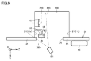
- FIG. 6 is a top view showing the machine tool during work transfer.
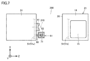
- FIG. 7 is a front view showing the machine tool during work transfer.
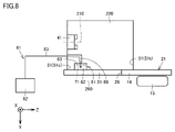
- FIG. 8 is a top view showing the machine tool during work machining.
- FIG. 9 is a front view showing the machine tool during work machining.
- transport mechanism 120 grips a workpiece with hand 129 and moves at least one of first arm 126, second arm 127 and third arm 128.
- first arm 126, second arm 127 and third arm 128 By operating one arm, a workpiece is carried from the external space 260 into the machining area 200 and mounted on the workpiece spindle 41, or the workpiece mounted on the workpiece spindle 41 is transferred from the machining area 200 to the external space 260. Carry it out.
- the door portion 31 When the work is transported to the machine tool 10 by the transport mechanism 120, the door portion 31 is in the second state in which the processing area 200 is opened toward the external space 260. A work is conveyed between the processing area 200 and the outer space 260 through the opening 26 . On the other hand, when the tool held on the tool post 12 is used to machine the work held on the work spindle 41, the door portion 31 is in the first state separating the machining area 200 and the external space 260. , the processing area 200 is closed.
- the control device 140 captures the identifier 71 with the camera 131 when the automated guided vehicle 135 is arranged at a predetermined position with respect to the machine tool 10 and the robot 125 is in the imaging posture by a teaching operation in advance.
- the image is stored as a reference image.
- the camera 131 captures an image of the identifier 71 when the unmanned guided vehicle 135 is placed at a predetermined position with respect to the machine tool 10 and the robot 125 is in the imaging posture when the transport mechanism 120 transports the workpiece to the machine tool 10 .
- Camera 131 is placed in external space 260 when photographing identifier 71 .
- camera 131 may be placed in processing area 200 when capturing identifier 71 .
- the control device 140 determines the imaging posture during the teaching operation. , and the imaging posture during workpiece transfer, and the correction amount of the posture of the robot 125 is calculated based on the estimated error amount. The control device 140 controls the motion of the robot 125 based on the calculated correction amount.
- an imaging range 310 by the camera 131 is indicated by a chain double-dashed line.
- the imaging range 310 preferably includes the work spindle 41 in addition to the identifier 71 .
- the control device 140 may calculate the coordinates of the workpiece spindle 41 (chuck) with the identifier 71 as a reference, based on the captured identifier 71 and the image of the workpiece spindle 41 . This makes it possible to operate the robot 125 with respect to the workpiece spindle 41 with higher accuracy.
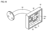
- FIG. 10 is a perspective view showing an identifier mounting structure within the processing area.
- the identifier 71 is supported by one of the door portion 31 and the in-machine cover 51 in the processing area 200. As shown in FIG. In this embodiment, the identifier 71 is supported by the inboard cover 51 .
- the machine tool 10 further has a support bar 68 and a plate 63.
- the support bar 68 is connected to the first in-machine side cover 51 s of the in-machine cover 51 .
- the support bar 68 extends in the +Z-axis direction from the first inboard side cover 51s, bends 90°, and extends in the +Y-axis direction.
- the plate 63 is connected to the tip of the support bar 68 .
- the plate 63 has a flat portion 63a.
- the flat portion 63a has a flat plate shape.
- the planar portion 63a extends in a planar direction intersecting the Y-axis direction.
- the planar portion 63a extends in a planar direction orthogonal to the Y-axis direction.
- An identifier 71 is attached to the planar portion 63a.
- the identifier 71 is supported by the in-machine cover 51 (first in-machine side cover 51 s) via the support bar 68 and the plate 63 .
- the transport mechanism 120 can be properly positioned with respect to the machine tool 10 .
- the identifier 71 is arranged below the rotation center axis 210 of the work spindle 41 in the X-axis direction (vertical direction).
- the identifier 71 may be arranged at a height overlapping the rotation center axis 210 in the X-axis direction (vertical direction), or may be arranged above the rotation center axis 210 .
- the identifier 71 is arranged between the door portion 31 (front door portion 33) and the work spindle 41 in the Y-axis direction.
- the identifier 71 is provided at a position closer to the first in-machine side cover 51s than the second in-machine side cover 51t in the Z-axis direction.
- the identifier 71 is positioned to face the door portion 31 when the door portion 31 is in the first state separating the processing area 200 and the external space 260. .
- the identifier 71 faces the door portion 31 with a gap therebetween in the Y-axis direction.
- the identifier 71 when the door portion 31 is in the second state in which the processing area 200 is opened toward the external space 260, the identifier 71 is further away from the door portion 31 than in the first state. are positioned The identifier 71 does not face the door portion 31 in the Y-axis direction, but faces the opening surface formed by the opening portion 26 (the front opening portion 27). When the door portion 31 is in the second state, the door portion 31 slides to a position shifted from the identifier 71 in the ⁇ Z-axis direction.
- the identifier 71 faces the door portion 31.
- the door portion 31 is an existing facility provided in the machine tool 10 . Therefore, there is no need to provide a special device such as a cover or an actuator to prevent the identifier 71 from being soiled, and the machine tool 10 can be simplified in configuration.
- the identifier 71 is further away from the door portion 31 than in the first state.
- the identifier 71 kept clean can be imaged by the camera 131 by being positioned by the camera 131 .
- the transport mechanism 120 can be properly positioned with respect to the machine tool 10 .
- the machine tool 10 further has an eaves portion 62 and a seal portion 66 as a foreign matter entry prevention mechanism.
- the eaves portion 62 and the seal portion 66 are provided so as to separate the space around the identifier 71 from the processing area 200 when the door portion 31 is in the first state. prevent entry.
- the canopy portion 62 is provided along the peripheral portion of the plate 63 so as to surround the identifier 71 .
- the eaves portion 62 extends from the plate 63 toward the door portion 31 in the first state.
- the eaves portion 62 extends from the plate 63 in the +Y-axis direction.
- the eaves portion 62 may have a shape that surrounds the identifier 71 from above and from the sides. That is, the eaves portion 62 may be configured without the bottom portion 62m shown in FIG.
- the seal portion 66 is made of an elastically deformable material such as rubber.
- the seal portion 66 is provided at the tip portion of the eaves portion 62 extending from the plate 63 toward the door portion 31 .
- the seal portion 66 is in contact with the door portion 31 in the first state.
- the identifier 71 can be kept cleaner by preventing foreign matter from entering toward the identifier 71 with the eaves portion 62 and the seal portion 66 .
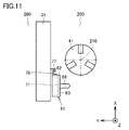
- FIG. 11 is a side view of the inside of the processing area showing a modification of the foreign matter entry prevention mechanism.
- machine tool 10 has labyrinth members 76 and 77 instead of seal portion 66 in FIG.
- the labyrinth member 76 and the labyrinth member 77 are provided on the eaves portion 62 and the door portion 31, respectively.
- the labyrinth member 76 and the labyrinth member 77 are formed of angles with L-shaped cross sections and extend in the Z-axis direction.
- the labyrinth member 76 and the labyrinth member 77 are arranged to face each other with a gap in the Y-axis direction, thereby forming a labyrinth structure.
- the labyrinth structure formed by the labyrinth members 76 and 77 allows the identifier 71 to be seen from above the eaves portion 62 . It is possible to prevent foreign matter from entering toward the
- the machine tool 10 may have an air supply mechanism 81 for supplying air to the space around the identifier 71.
- the air supply mechanism 81 has a compressor 82 and an air pipe 83 .
- An air pipe 83 extends from the compressor 82 , passes through the support bar 68 , and communicates with the space around the identifier 71 surrounded by the eaves 62 .
- air from the compressor 82 is supplied to the space around the identifier 71 through the air pipe 83 .
- machine tool 10 uses conveying mechanism 120 having camera 131 to operate processing area 200 as an internal space. , and an external space 260 on the outside thereof to transport a work as a transport object.
- the machine tool 10 has a door portion as a movable cover capable of operating between a first state separating the machining area 200 and the external space 260 and a second state opening the machining area 200 toward the external space 260. 31, a machine inner cover 51 as a fixed cover provided in the machining area 200, and a machine inner cover 51 as a first cover which is either the door portion 31 or the machine inner cover 51 in the machining area 200. and an identifier 71 imaged by a camera 131 for positioning the transport mechanism 120 with respect to 10 .
- the identifier 71 is positioned to face the door portion 31 as a second cover, which is the other of the door portion 31 and the in-machine cover 51, and the door portion 31 is placed in the first state. In the second state, it is positioned farther from the door portion 31 than in the first state.
- the transfer mechanism 120 can be properly positioned with respect to the machine tool 10 by keeping the identifier 71 clean. As a result, the operation of transporting the work to the work spindle 41 by the transport mechanism 120 can be performed stably and smoothly.
- the transport mechanism is not limited to those using the automatic guided vehicle 135 and the robot 125, and may be an automated fork mechanism, for example.
- the machine tool in the present invention is not limited to a lathe, and may be, for example, a vertical machining center or a horizontal machining center, or a multitasking machine having a turning function using a stationary tool and a milling function using a rotary tool.
- it may be an AM/SM hybrid machine capable of additional machining (AM (additive manufacturing) machining) and SM (subtractive manufacturing) machining of the workpiece.
- AM additive manufacturing
- SM subtractive manufacturing
- FIG. 12 is a top view showing a machine tool (during work transfer) according to Embodiment 2 of the present invention.
- FIG. 13 is a front view showing a machine tool (during work transfer) according to Embodiment 2 of the present invention.
- FIG. 14 is a top view showing a machine tool (during workpiece machining) according to Embodiment 2 of the present invention.
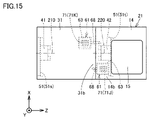
- FIG. 15 is a front view showing a machine tool (during workpiece machining) according to Embodiment 2 of the present invention.
- the machine tool according to the present embodiment has basically the same structure as the machine tool 10 according to the first embodiment. Hereinafter, descriptions of overlapping structures will not be repeated.
- the machine tool according to the present embodiment further has an opposing work main shaft 42 for rotating the work about a rotation center axis 220 parallel to the Z-axis.
- the opposing work main shaft 42 is provided facing the work main shaft 41 in the Z-axis direction.
- Rotation center axis 210 and rotation center axis 220 extend on a straight line.
- the opposing work main shaft 42 is provided so as to protrude in the -Z-axis direction from the second in-machine side cover 51t.
- the second front cover 14 has a first protrusion 14b.
- the first projecting portion 14b is a part of the second front cover 14 and has a plate shape parallel to the X-axis-Z-axis plane.
- the first protrusion 14b is provided to protrude in the ⁇ Z-axis direction from the second in-machine side cover 51t.
- the end of the first protrusion 14b in the ⁇ Z-axis direction defines the opening 26.
- the first projecting portion 14 b is provided in the processing area 200 .
- the first protruding portion 14b defines a processing area 200 together with the in-machine cover 51 and the door portion 31 .
- the door portion 31 has a second projecting portion 31b.
- the second projecting portion 31b is part of the front door portion 33 .
- a part of the upper door part 32 may be sufficient as the 2nd protrusion part 31b.
- the second protrusion 31b is provided to protrude in the +Z-axis direction more than the first in-machine side cover 51s when the door 31 is in the second state.
- the machine tool has an identifier 71J and an identifier 71K as identifiers 71.
- the camera 131 captures the identifier 71J when the transport mechanism 120 transports the work with respect to the work spindle 41 .
- the camera 131 captures an image of the identifier 71K when the transport mechanism 120 transports the work with respect to the opposing work spindle 42 .
- the identifier 71J is supported by the door portion 31 in the processing area 200.
- the identifier 71J is supported by the door portion 31 via the support bar 68 and the plate 63. As shown in FIG.
- the support bar 68 is connected to the second projecting portion 31b of the door portion 31 .
- Identifier 71J is provided in processing area 200 at a position corresponding to identifier 71 in the first embodiment.
- the identifier 71J is provided so as to be slidable in the Z-axis direction together with the door portion 31 .
- the identifier 71K is supported by the first projecting portion 14b of the second front cover 14 in the processing area 200.
- the identifier 71K is supported by the first protrusion 14b of the second front cover 14 via the support bar 68 and the plate 63.
- the support bar 68 is connected to the first projecting portion 14b of the second front cover 14. As shown in FIG.
- the identifier 71K is provided at a position shifted from the identifier 71J in the X-axis direction (vertical direction).
- the identifier 71K is provided above the identifier 71J.
- the identifier 71K is provided at a position closer to the second in-machine side cover 51t than the first in-machine side cover 51s in the Z-axis direction.
- the identifier 71J is positioned on the first projecting portion 14b of the second front cover 14. is positioned opposite the The identifier 71J faces the first projecting portion 14b of the second front cover 14 with a gap therebetween in the Y-axis direction.
- the identifier 71K is positioned to face the door portion 31 when the door portion 31 is in the first state separating the processing area 200 and the external space 260 .
- the identifier 71K faces the door portion 31 with a gap therebetween in the Y-axis direction.
- the identifier 71J is located on the second front cover 14 rather than in the first state. is positioned away from the first protrusion 14b.
- the identifier 71J does not face the first protrusion 14b of the second front cover 14 in the Y-axis direction, but faces the opening surface formed by the opening 26 (front opening 27).
- the identifier 71K When the door portion 31 is in the second state in which the processing area 200 is opened toward the external space 260, the identifier 71K is positioned farther from the door portion 31 than in the first state.
- the identifier 71K does not face the door portion 31 in the Y-axis direction, but faces the opening surface formed by the opening portion 26 (the front opening portion 27).
- the door portion 31 slides to a position shifted in the ⁇ Z-axis direction from the identifier 71K.
- the machine tool according to the present embodiment has a first state separating machining area 200 and external space 260, and machining area 200.
- Door portion 31 as a movable cover operable between a second state in which it opens toward the external space 260, and the first protruding portion 14b of the second front cover 14 as a fixed cover provided in the processing area 200.
- the first protrusion 14b as a first cover, which is either one of the door 31 and the first protrusion 14b in the processing area 200, and a camera for positioning the transport mechanism 120 with respect to the machine tool.
- the identifier 71K is positioned to face the door portion 31 as a second cover, which is the other of the door portion 31 and the first projecting portion 14b. is set to the second state, it is positioned farther from the door portion 31 than in the first state.
- the machine tool in the present embodiment is supported by the door portion 31 as the first cover, which is either the door portion 31 or the first projecting portion 14b, in the processing area 200. and an identifier 71J imaged by the camera 131 for positioning.
- the identifier 71J is positioned to face the first projecting portion 14b as a second cover, which is the other of the door portion 31 and the first projecting portion 14b, and the door When the portion 31 is in the second state, it is positioned farther from the first projecting portion 14b than in the first state.
- Embodiment 2 of the present invention which is configured in this manner, the same effects as those of Embodiment 1 can be obtained by keeping the identifier 71J and the identifier 71K clean during machining of the workpiece.
- FIG. 16 is a top view schematically showing a production system equipped with machine tools according to Embodiment 3 of the present invention.
- a machine tool according to the present embodiment has basically the same structure as machine tool 10 according to the first embodiment.
- descriptions of overlapping structures will not be repeated.
- the production system has a machine tool 410, a tool stocker 460, a transfer mechanism 120, and a controller 140 for controlling the transfer mechanism 120.
- the tool stocker 460 is arranged adjacent to the machine tool 410.
- Tool stocker 460 is a device that stocks a plurality of tools.
- Machine tool 410 is a machining center.
- Machine tool 410 may be a vertical machining center or a horizontal machining center.
- Machine tool 410 may be a multi-task machine.
- the machine tool 410 has a tool magazine 415.
- the tool magazine 415 is a device that stores a plurality of tools in order to sequentially supply the tools to the machining area according to the purpose of machining.
- the tool magazine 415 stores tools such as drills, end mills, and milling cutters.
- the machine tool has a cover body 21.
- the cover body 21 defines the magazine internal area 250 and forms the appearance of the machine tool.
- a plurality of tools are stored in the magazine area 250 .
- An opening 426 is provided in the cover body 21 . The opening 426 opens the internal magazine area 250 to the external space 260 outside thereof.
- the cover body 21 has a main body cover 421 (fixed cover) and a door portion 431 (movable cover).
- the main body cover 421 defines a magazine internal area 250 .
- the door portion 431 is provided in the opening portion 426 .
- the door portion 431 operates between a first state (closed state) that separates the magazine internal area 250 and the external space 260 and a second state (open state) that opens the magazine internal area 250 toward the external space 260 . It is operable.
- the door portion 431 pivots about the hinge portion 432 between the first state and the second state. Note that FIG. 16 shows the door portion 431 in the first state.
- the machine tool 410 further has an identifier 71.
- the identifier 71 is provided in the in-magazine area 250 .
- the identifier 71 is supported by the main body cover 421 as a first cover, which is either one of the door portion 431 and the main body cover 421 in the processing area 200 .
- the identifier 71 When the door portion 431 is in the first state, the identifier 71 is positioned to face the door portion 431 as a second cover, which is the other of the door portion 431 and the body cover 421 . Identifier 71 is positioned further away from door portion 431 than in the first state when door portion 431 is in the second state.
- Embodiment 3 of the present invention configured in this way, the effects described in Embodiment 1 can be achieved in the same manner.
- This invention is applied, for example, to a production system equipped with an automatic transport mechanism that transports workpieces, tools, or the like.
Landscapes
- Engineering & Computer Science (AREA)
- Mechanical Engineering (AREA)
- Physics & Mathematics (AREA)
- Optics & Photonics (AREA)
- Auxiliary Devices For Machine Tools (AREA)
- Machine Tool Sensing Apparatuses (AREA)
- Automatic Tool Replacement In Machine Tools (AREA)
Abstract
工作機械は、カメラ(131)を有する搬送機構を用いて、内部空間(200)と、その外側の外部空間(260)との間でワークを搬送する作業を行なう。工作機械は、内部空間(200)および外部空間(260)の間を隔てる第1状態と、内部空間(200)を外部空間(260)に向けて開放する第2状態との間で動作可能な可動式カバー(31)と、内部空間(200)に設けられる固定式カバー(51)と、内部空間(200)において固定式カバー(51)により支持され、工作機械に対して搬送機構の位置決めを行なうためにカメラ(131)により撮像される識別子(71)とを備える。可動式カバー(31)が第1状態とされた場合に、識別子(71)は、可動式カバー(31)と対向して位置決めされ、可動式カバー(31)が第2状態とされた場合に、第1状態よりも可動式カバー(31)から遠ざかって位置決めされる。
Description
この発明は、工作機械に関する。
たとえば、特許第6785931号明細書(特許文献1)には、加工エリア内に姿勢補正用の識別図形が配置された工作機械と、識別図形を撮像するためのカメラを有し、工作機械に対して作業を行なうロボットとを備える生産システムが開示されている。
上述の特許文献1に開示されるように、工作機械に識別図形を配置し、その識別図形をカメラにより撮像することによって、工作機械に対してロボット等の搬送機構を位置決めすることが行なわれている。このような工作機械において、識別図形が、加工エリア内で生じる切屑、クーラントまたはミスト等の異物によって汚損されると、工作機械に対する搬送機構の位置決めを適正に行なうことが難しくなる。
そこでこの発明の目的は、上記の課題を解決することであり、搬送機構の位置決めが適正に行なわれる工作機械を提供することである。
この発明に従った工作機械は、カメラを有する搬送機構を用いて、内部空間と、その外側の外部空間との間で搬送対象物を搬送する作業が行なわれる工作機械である。工作機械は、内部空間および外部空間の間を隔てる第1状態と、内部空間を外部空間に向けて開放する第2状態との間で動作可能な可動式カバーと、内部空間に設けられる固定式カバーと、内部空間において可動式カバーおよび固定式カバーのいずれか一方である第1カバーにより支持され、工作機械に対して搬送機構の位置決めを行なうためにカメラにより撮像される識別子とを備える。可動式カバーが第1状態とされた場合に、識別子は、可動式カバーおよび固定式カバーのいずれか他方である第2カバーと対向して位置決めされ、可動式カバーが第2状態とされた場合に、第1状態よりも第2カバーから遠ざかって位置決めされる。
このように構成された工作機械によれば、可動式カバーが第1状態とされ、内部空間および外部空間の間が可動式カバーにより隔てられた場合に、識別子が第2カバーと対向して位置決めされることによって、内部空間におけるクーラント、切屑またはミスト等の異物が識別子を汚損することを抑制できる。一方、可動式カバーが第2状態とされ、内部空間が外部空間に向けて開放された場合に、識別子が第1状態よりも第2カバーから遠ざかって位置決めされることによって、清浄に保たれた識別子をカメラにより撮像することができる。これにより、工作機械に対する搬送機構の位置決めを適正に行なうことができる。
また好ましくは、内部空間は、ワークの加工が行なわれる加工エリア、または、複数の工具が格納されるマガジン内エリアである。可動式カバーは、加工エリアまたはマガジン内エリアを区画形成するカバー体に設けられる扉部である。
このように構成された工作機械によれば、識別子が、加工エリアまたはマガジン内エリアにおいて、クーラント、切屑またはミスト等により汚損されることを抑制できる。この場合に、可動式カバーが、加工エリアまたはマガジン内エリアを区画形成するカバー体に設けられる扉部であるため、扉部の開閉動作に伴って、第1状態および第2状態を得ることができる。
また好ましくは、工作機械は、可動式カバーが第1状態とされた場合に、識別子の周りの空間を、内部空間から隔てるように設けられ、内部空間から識別子に向けた異物の進入を防ぐ異物進入防止機構をさらに備える。
このように構成された工作機械によれば、異物が識別子を汚損することをさらに効果的に抑制できる。
また好ましくは、工作機械は、識別子の周りの空間に空気を供給する空気供給機構をさらに備える。
このように構成された工作機械によれば、識別子の周りの空間の圧力を高めることによって、内部空間から識別子に向けた異物の進入をさらに効果的に防ぐことができる。
また好ましくは、識別子は、図形である。第1カバーは、平面形状を有し、図形が付される平面部を含む。
このように構成された工作機械によれば、図形が平面形状を有する平面部に付されることによって、図形を平面状に保つことができる。これにより、工作機械に対する搬送機構の位置決めをさらに適正に行なうことができる。
以上に説明したように、この発明に従えば、搬送機構の位置決めが適正に行なわれる工作機械を提供することができる。
この発明の実施の形態について、図面を参照して説明する。なお、以下で参照する図面では、同一またはそれに相当する部材には、同じ番号が付されている。
(実施の形態1)
図1は、この発明の実施の形態1における工作機械を備えた生産システムを模式的に示す上面図である。図2は、図1中の生産システムに用いられる搬送機構を示す斜視図である。
図1は、この発明の実施の形態1における工作機械を備えた生産システムを模式的に示す上面図である。図2は、図1中の生産システムに用いられる搬送機構を示す斜視図である。
図1および図2を参照して、生産システムは、工作機械10と、材料ストッカ122および製品ストッカ121と、搬送機構120と、搬送機構120を制御するための制御装置140とを有する。
材料ストッカ122は、図1において工作機械10の左隣に配設され、当該工作機械10で加工される複数の材料(加工前ワーク)をストックする装置である。製品ストッカ121は、図1において工作機械10の右隣に配設され、当該工作機械10で加工された複数の製品、または、半製品(加工済ワーク)をストックする装置である。
搬送機構120は、工作機械10に対して搬送対象物としてワークを搬送する。搬送機構120は、無人搬送車135およびロボット125を有する。
ロボット125は、無人搬送車135に搭載されている。ロボット125は、無人搬送車135の上面である載置面136に搭載されている。無人搬送車135には、オペレータが携帯可能な操作盤137が付設されている。操作盤137は、データの入出力を行なうための入出力部と、当該無人搬送車135およびロボット125を手動操作するための操作部と、画面表示可能なディスプレイとを有する。
無人搬送車135は、工場内における自身の位置を認識可能なセンサ(たとえば、レーザ光を用いた距離計測センサ)を有する。無人搬送車135は、制御装置140による制御に基づいて、工作機械10、材料ストッカ122および製品ストッカ121が配設される領域を含む工場内を無軌道で走行するように構成されている。
ロボット125は、第1アーム126、第2アーム127および第3アーム128を有する多関節型のロボットである。ロボット125は、エンドエフェクタとしてのハンド129をさらに有する。ハンド129は、第3アーム128の先端部に取り付けられている。搬送機構120(ロボット125)は、カメラ131をさらに有する。カメラ131は、ステレオカメラである。カメラ131は、取り付けバー130を介して、第3アーム128に取り付けられている。
図3は、図1中の工作機械を示す正面図である。図3を参照して、工作機械10は、回転するワークに工具を接触させることによって、ワーク加工を行なう旋盤である。工作機械10は、コンピュータによる数値制御によって、ワーク加工のための各種動作が自動化されたNC(Numerically Control)工作機械である。
本明細書においては、工作機械10の左右方向(幅方向)に平行で、水平方向に延びる軸を「Z軸」といい、工作機械10の前後方向(奥行き方向)に平行で、水平方向に延びる軸を「Y軸」といい、鉛直方向に延びる軸を「X軸」という。図3中における右方向を「+Z軸方向」といい、左方向を「-Z軸方向」という。図3中における紙面の手前方向を「+Y軸方向」といい、奥方向を「-Y軸方向」という。図3中における上方向を「+X軸方向」といい、下方向を「-X軸方向」という。
なお、工作機械10の構造を説明する便宜上、上記のとおりX軸、Y軸およびZ軸を設定したが、これらは、旋盤で定義されるX軸、Y軸およびZ軸と必ずしも一致するものではない。
工作機械10は、カバー体21を有する。カバー体21は、加工エリア200を区画形成するとともに、工作機械10の外観をなしている。加工エリア200は、ワークの加工が行なわれる空間であり、ワーク加工に伴う切屑、クーラントまたはミスト等の異物が加工エリア200の外側の外部空間260(後出の図6等を参照)に漏出しないように密閉されている。
加工エリア200には、Z軸に平行な回転中心軸210を中心にワークを回転させるためのワーク主軸41と、複数の工具を保持し、Z軸方向に平行な旋回中心軸230を中心に旋回可能なタレットタイプの刃物台12とが配置されている。加工エリア200には、ワークの回転中心を支持するための心押し台、または、Z軸方向においてワーク主軸41と対向して配置される対向ワーク主軸がさらに配置されてもよい。
カバー体21には、開口部26が設けられている。開口部26は、加工エリア200を外部空間260に開放している。
開口部26は、前方開口部27と、上方開口部28とを有する。前方開口部27は、加工エリア200を+Y軸方向に向けて開放している。作業者は、加工エリア200にアクセスする場合に、前方開口部27の開口面と対向する位置に立つ。上方開口部28は、加工エリア200の上方に配置されている。上方開口部28は、前方開口部27から連なっている。前方開口部27の上端部(+X軸方向における端部)は、上方開口部28の前端部(+Y軸方向における端部)に連なっている。上方開口部28は、加工エリア200を+X軸方向に向けて開放している。
カバー体21は、第1正面カバー16および第2正面カバー14と、天井カバー19と、機内カバー51とを有する。第1正面カバー16、第2正面カバー14および天井カバー19は、工作機械10の外観をなしている。機内カバー51は、加工エリア200に設けられている。機内カバー51は、加工エリア200を区画形成している。
第1正面カバー16および第2正面カバー14は、Z軸方向において、開口部26の両側にそれぞれ設けられている。第1正面カバー16の内側には、ワーク主軸41等が配置されている。第2正面カバー14には、操作パネル15が設けられている。操作パネル15は、作業者が工作機械10を操作する際に用いる各種のボタンおよびスイッチ、ならびに、工作機械10におけるワークの加工状態等を示す表示部などを含む。
天井カバー19は、工作機械10の天井に配置されている。第1正面カバー16、第2正面カバー14および天井カバー19により、開口部26が画定されている。
機内カバー51は、第1機内サイドカバー51sと、第2機内サイドカバー51tとを有する。
第1機内サイドカバー51sおよび第2機内サイドカバー51tは、Z軸方向に直交する平板形状を有する。第1機内サイドカバー51sおよび第2機内サイドカバー51tは、Z軸方向において、互いに離れて対向している。第1機内サイドカバー51sは、-Z軸方向における加工エリア200の端部に設けられている。ワーク主軸41は、第1機内サイドカバー51sから+Z軸方向に突出するように設けられている。第2機内サイドカバー51tは、+Z軸方向における加工エリア200の端部に設けられている。
カバー体21は、扉部31をさらに有する。扉部31は、開口部26に設けられている。
扉部31は、開口部26を閉塞し、加工エリア200および外部空間260の間を隔てる第1状態(閉状態)と、加工エリア200を外部空間260に向けて開放する第2状態(開状態)との間で動作可能である。扉部31は、第1状態および第2状態の間においてスライド動作する。扉部31は、第1状態および第2状態の間において、水平方向にスライド動作する。扉部31は、第1状態および第2状態の間において、Z軸方向にスライド動作する。なお、図3中には、第2状態とされた扉部31が示されている。
扉部31は、工作機械10の外観をなしている。扉部31は、第1状態とされた場合に、機内カバー51とともに加工エリア200を区画形成している。扉部31は、第2状態とされた場合に、第1正面カバー16と重なって配置されている。
扉部31は、前方扉部33と、上方扉部32とを有する。扉部31が第1状態とされた場合に、前方扉部33は、前方開口部27を閉塞し、上方扉部32は、上方開口部28を閉塞する。前方扉部33は、全体として、X軸-Z軸平面に平行な板形状を有する。前方扉部33には、透明窓34が設けられている。上方扉部32は、全体として、Y軸-Z軸平面に平行な板形状を有する。前方扉部33の上端部(+X軸方向における端部)と、上方扉部32の前端部(+Y軸方向における端部)とが繋がって、角部をなしている。
典型的には、扉部31は、ピストンまたはモータ等のアクチュエータによってスライドされる自動扉である。
図4は、識別子を示す正面図である。図5は、ワーク搬送時にカメラにより撮像された識別子の画像の一例を示す図である。図3から図5を参照して、工作機械10は、識別子71をさらに有する。識別子71は、工作機械10に対して搬送機構120の位置決めを行なうためにカメラ131により撮像される。
識別子71は、図形である。識別子71は、平面図形である。識別子71は、平面状のシートに描かれている。識別子71は、矩形形状を有する複数の画素が2次元に配列されたマトリクス構造を有するものであり、各画素が、白色または黒色で表示されている。
識別子71は、加工エリア200内に設けられている。識別子71は、+Y軸方向を向いて設けられている。識別子71は、開口部26(前方開口部27)がなす開口面と対向して設けられている。識別子71は、扉部31のスライド方向(Z軸方向)と平行に配置されている。なお、工作機械10における識別子71の取り付け構造については、後で詳細に説明する。
図6は、ワーク搬送時における工作機械を示す上面図である。図7は、ワーク搬送時における工作機械を示す正面図である。図8は、ワーク加工時における工作機械を示す上面図である。図9は、ワーク加工時における工作機械を示す正面図である。
図1から図3、および、図6から図9を参照して、搬送機構120は、ハンド129によりワークを把持しつつ、第1アーム126、第2アーム127および第3アーム128のうちの少なくとも1つのアームを動作させることによって、ワークを外部空間260から加工エリア200内に搬入し、ワーク主軸41に装着したり、ワーク主軸41に装着されたワークを、加工エリア200内から外部空間260に搬出したりする。
搬送機構120による工作機械10に対するワークの搬送時、扉部31は、加工エリア200を外部空間260に向けて開放する第2状態とされる。ワークは、開口部26を通じて、加工エリア200および外部空間260の間を搬送される。一方、刃物台12に保持された工具を用いて、ワーク主軸41に保持されたワークを加工するワーク加工時、扉部31は、加工エリア200および外部空間260の間を隔てる第1状態とされ、加工エリア200が密閉される。
制御装置140は、予めのティーチング操作によって、無人搬送車135が工作機械10に対して所定位置に配置され、ロボット125が撮像姿勢にあるときに、識別子71をカメラ131により撮像して得られた画像を、基準画像として記憶している。
カメラ131は、搬送機構120による工作機械10に対するワークの搬送時、無人搬送車135が工作機械10に対して所定位置に配置され、ロボット125が撮像姿勢にあるときに、識別子71を撮像する。カメラ131は、識別子71を撮影する時に外部空間260に配置されている。加工エリア200における識別子71の配置によっては、カメラ131は、識別子71を撮影する時に加工エリア200に配置されてもよい。
制御装置140は、ワーク搬送時に得られた識別子71の画像(図5に一例が示されている)と、ティーチング操作によって得られた識別子71の基準画像とに基づいて、ティーチング操作時の撮像姿勢と、ワーク搬送時の撮像姿勢との間の誤差量を推定し、推定された誤差量に基づいて、ロボット125の姿勢の補正量を算出する。制御装置140は、算出された補正量に基づいて、ロボット125の動作を制御する。
図6中には、カメラ131による撮像範囲310が2点鎖線により示されている。撮像範囲310は、識別子71に加えて、ワーク主軸41を含むことが好ましい。この場合に、制御装置140は、撮像された識別子71およびワーク主軸41の画像に基づいて、識別子71を基準とするワーク主軸41(チャック)の座標を算出してもよい。これにより、ワーク主軸41に対してロボット125をより高精度に動作させることが可能となる。
続いて、識別子71の取り付け構造について詳細に説明する。図10は、加工エリア内における識別子の取り付け構造を示す斜視図である。
図6から図10を参照して、識別子71は、加工エリア200において扉部31および機内カバー51のいずれか一方により支持されている。本実施の形態では、識別子71が、機内カバー51により支持されている。
工作機械10は、支持バー68と、プレート63とをさらに有する。支持バー68は、機内カバー51の第1機内サイドカバー51sに接続されている。支持バー68は、第1機内サイドカバー51sから+Z軸方向に延出し、90°曲がって、+Y軸方向に延びている。
プレート63は、支持バー68の先端部に接続されている。プレート63は、平面部63aを有する。平面部63aは、平板形状を有する。平面部63aは、Y軸方向に交差する平面方向に延在している。平面部63aは、Y軸方向に直交する平面方向に延在している。平面部63aには、識別子71が付されている。識別子71は、支持バー68およびプレート63を介して、機内カバー51(第1機内サイドカバー51s)により支持されている。
識別子71が平面部63aに付されることによって、平面図形である識別子71を平面状に保つことができる。これにより、工作機械10に対する搬送機構120の位置決めを適正に行なうことができる。
識別子71は、X軸方向(上下方向)において、ワーク主軸41の回転中心軸210よりも下方に配置されている。識別子71は、X軸方向(上下方向)において、回転中心軸210と重なる高さに配置されてもよいし、回転中心軸210よりも上方に配置されてもよい。識別子71は、Y軸方向において、扉部31(前方扉部33)と、ワーク主軸41との間に配置されている。識別子71は、Z軸方向において、第2機内サイドカバー51tよりも第1機内サイドカバー51s寄りの位置に設けられている。
図8および図9に示されるように、扉部31が加工エリア200および外部空間260の間を隔てる第1状態とされた場合に、識別子71は、扉部31と対向して位置決めされている。識別子71は、Y軸方向において、扉部31と隙間を設けて対向している。
図6および図7に示されるように、扉部31が加工エリア200を外部空間260に向けて開放する第2状態とされた場合に、識別子71は、第1状態よりも扉部31から遠ざかって位置決めされている。識別子71は、Y軸方向において、扉部31と対向せず、開口部26(前方開口部27)がなす開口面と対向している。扉部31は、第2状態とされた場合に、識別子71よりも-Z軸方向にずれた位置までスライド動作する。
このような構成によれば、図8および図9に示されるように、加工エリア200におけるワーク加工のため、扉部31が第1状態とされた場合に、識別子71が扉部31と対向して位置決めされることによって、ワーク加工に伴って加工エリア200で生じるクーラント、切屑またはミスト等の異物が識別子71を汚損することを抑制できる。この際、扉部31は、工作機械10に備わった既存の設備である。このため、識別子71の汚損を防ぐためのカバー体またはアクチュエータ等の特別の装置を設ける必要がなく、工作機械10を簡易な構成にできる。
図6および図7に示されるように、搬送機構120による工作機械10に対するワーク搬送のため、扉部31が第2状態とされた場合に、識別子71が第1状態よりも扉部31から遠ざかって位置決めされることによって、清浄に保たれた識別子71をカメラ131により撮像することができる。これにより、工作機械10に対する搬送機構120の位置決めを適正に行なうことができる。
工作機械10は、異物進入防止機構としての庇部62およびシール部66をさらに有する。庇部62およびシール部66は、扉部31が第1状態とされた場合に、識別子71の周りの空間を加工エリア200から隔てるように設けられ、加工エリア200から識別子71に向けた異物の進入を防ぐ。
庇部62は、識別子71を取り囲むように、プレート63の周縁部に沿って設けられている。庇部62は、プレート63から第1状態とされた扉部31に向かって延出している。庇部62は、プレート63から+Y軸方向に向けて延出している。
なお、庇部62は、識別子71を上方および側方から囲む形状であってもよい。すなわち、庇部62は、図10に示される底部62mを有しない構成であってもよい。
シール部66は、ゴム等の弾性変形可能な材料から形成されている。シール部66は、プレート63から扉部31に向かって延出する庇部62の先端部に設けられている。シール部66は、第1状態とされた扉部31と接触している。
このような構成によれば、庇部62およびシール部66により識別子71に向けた異物の進入を防ぐことによって、識別子71をより清浄に保つことができる。
図11は、異物進入防止機構の変形例を示す加工エリア内の側面図である。図11を参照して、本変形例では、工作機械10が、図10中のシール部66に替わって、ラビリンス部材76およびラビリンス部材77を有する。
ラビリンス部材76およびラビリンス部材77は、それぞれ、庇部62および扉部31に設けられている。ラビリンス部材76およびラビリンス部材77は、L字断面のアングルからなり、Z軸方向に延びている。ラビリンス部材76およびラビリンス部材77は、Y軸方向において互いに隙間を設けて対向して配置されることによって、ラビリンス構造を構成している。
このような構成によれば、庇部62および扉部31の間に微小な隙間が生じる構成であっても、ラビリンス部材76およびラビリンス部材77がなすラビリンス構造によって、庇部62の上方から識別子71に向けた異物の進入を防ぐことができる。
図8を参照して、工作機械10は、識別子71の周りの空間に空気を供給するための空気供給機構81を有してもよい。空気供給機構81は、コンプレッサ82と、エア配管83とを有する。エア配管83は、コンプレッサ82から延出し、支持バー68を通って、庇部62により囲まれた識別子71の周りの空間に連通している。加工エリア200におけるワーク加工のため、扉部31が第1状態とされた場合に、コンプレッサ82からの空気がエア配管83を通じて識別子71の周りの空間に供給される。
このような構成によれば、識別子71の周りの空間の圧力を高めることによって、加工エリア200から識別子71に向けた異物の進入をさらに効果的に防ぐことができる。
以上に説明した、この発明の実施の形態1における工作機械10の構造をまとめると、本実施の形態における工作機械10は、カメラ131を有する搬送機構120を用いて、内部空間としての加工エリア200と、その外側の外部空間260との間で搬送対象物としてのワークを搬送する作業を行なう。
工作機械10は、加工エリア200および外部空間260の間を隔てる第1状態と、加工エリア200を外部空間260に向けて開放する第2状態との間で動作可能な可動式カバーとしての扉部31と、加工エリア200に設けられる固定式カバーとしての機内カバー51と、加工エリア200において扉部31および機内カバー51のいずれか一方である第1カバーとしての機内カバー51により支持され、工作機械10に対して搬送機構120の位置決めを行なうためにカメラ131により撮像される識別子71とを備える。
扉部31が第1状態とされた場合に、識別子71は、扉部31および機内カバー51のいずれか他方である第2カバーとしての扉部31と対向して位置決めされ、扉部31が第2状態とされた場合に、第1状態よりも扉部31から遠ざかって位置決めされる。
このように構成された、この発明の実施の形態1における工作機械10によれば、識別子71を清浄に保つことにより、工作機械10に対する搬送機構120の位置決めを適正に行なうことができる。これにより、搬送機構120によりワーク主軸41に対してワークを搬送する作業を、安定かつ円滑に行なうことができる。
なお、本実施の形態では、搬送機構による搬送対象物がワークである場合を説明したが、これに限られず、搬送対象物は、工具、ワーク把持用のチャック爪または治具などであってもよい。搬送機構は、無人搬送車135およびロボット125を利用したものに限られず、たとえば、自動化されたフォーク機構であってもよい。
本発明における工作機械は、旋盤に限られず、たとえば、立形マシニングセンタまたは横形マシニングセンタであってもよいし、固定工具を用いた旋削機能と、回転工具を用いたミーリング機能とを有する複合加工機であってもよいし、ワークの付加加工(AM(Additive manufacturing)加工)と、ワークの除去加工(SM(Subtractive manufacturing)加工)とが可能なAM/SMハイブリッド加工機であってもよい。
(実施の形態2)
図12は、この発明の実施の形態2における工作機械(ワーク搬送時)を示す上面図である。図13は、この発明の実施の形態2における工作機械(ワーク搬送時)を示す正面図である。図14は、この発明の実施の形態2における工作機械(ワーク加工時)を示す上面図である。図15は、この発明の実施の形態2における工作機械(ワーク加工時)を示す正面図である。
図12は、この発明の実施の形態2における工作機械(ワーク搬送時)を示す上面図である。図13は、この発明の実施の形態2における工作機械(ワーク搬送時)を示す正面図である。図14は、この発明の実施の形態2における工作機械(ワーク加工時)を示す上面図である。図15は、この発明の実施の形態2における工作機械(ワーク加工時)を示す正面図である。
本実施の形態における工作機械は、実施の形態1における工作機械10と比較して、基本的には同様の構造を備える。以下、重複する構造については、その説明を繰り返さない。
図12から図15を参照して、本実施の形態における工作機械は、Z軸に平行な回転中心軸220を中心にワークを回転させるための対向ワーク主軸42をさらに有する。対向ワーク主軸42は、Z軸方向において、ワーク主軸41と対向して設けられている。回転中心軸210と、回転中心軸220とは、一直線上に延びている。対向ワーク主軸42は、第2機内サイドカバー51tから-Z軸方向に突出するように設けられている。
第2正面カバー14は、第1突出部14bを有する。第1突出部14bは、第2正面カバー14の一部であって、X軸-Z軸平面に平行な板形状を有する。第1突出部14bは、第2機内サイドカバー51tよりも-Z軸方向に突出するように設けられている。-Z軸方向における第1突出部14bの端部が、開口部26を確定している。第1突出部14bは、加工エリア200に設けられている。扉部31が第2状態とされた場合に、第1突出部14bは、機内カバー51および扉部31とともに、加工エリア200を区画形成している。
扉部31は、第2突出部31bを有する。第2突出部31bは、前方扉部33の一部である。第2突出部31bは、上方扉部32の一部であってもよい。扉部31が第2状態とされた場合に、第2突出部31bは、第1機内サイドカバー51sよりも+Z軸方向に突出するように設けられている。
工作機械は、識別子71として、識別子71Jおよび識別子71Kを有する。カメラ131は、搬送機構120によりワーク主軸41に対してワークを搬送する場合に、識別子71Jを撮像する。カメラ131は、搬送機構120により対向ワーク主軸42に対してワークを搬送する場合に、識別子71Kを撮像する。
識別子71Jは、加工エリア200において扉部31により支持されている。識別子71Jは、支持バー68およびプレート63を介して、扉部31により支持されている。支持バー68は、扉部31の第2突出部31bに接続されている。識別子71Jは、加工エリア200において、実施の形態1における識別子71に対応する位置に設けられている。識別子71Jは、扉部31とともに、Z軸方向にスライド動作が可能なように設けられている。
識別子71Kは、加工エリア200において第2正面カバー14の第1突出部14bにより支持されている。識別子71Kは、支持バー68およびプレート63を介して、第2正面カバー14の第1突出部14bにより支持されている。支持バー68は、第2正面カバー14の第1突出部14bに接続されている。
識別子71Kは、X軸方向(上下方向)において、識別子71Jからずれた位置に設けられている。識別子71Kは、識別子71Jよりも上方に設けられている。識別子71Kは、Z軸方向において、第1機内サイドカバー51sよりも第2機内サイドカバー51t寄りの位置に設けられている。
図14および図15に示されるように、扉部31が加工エリア200および外部空間260の間を隔てる第1状態とされた場合に、識別子71Jは、第2正面カバー14の第1突出部14bと対向して位置決めされている。識別子71Jは、Y軸方向において、第2正面カバー14の第1突出部14bと隙間を設けて対向している。
扉部31が加工エリア200および外部空間260の間を隔てる第1状態とされた場合に、識別子71Kは、扉部31と対向して位置決めされている。識別子71Kは、Y軸方向において、扉部31と隙間を設けて対向している。
図12および図13に示されるように、扉部31が加工エリア200を外部空間260に向けて開放する第2状態とされた場合に、識別子71Jは、第1状態よりも第2正面カバー14の第1突出部14bから遠ざかって位置決めされている。識別子71Jは、Y軸方向において、第2正面カバー14の第1突出部14bと対向せず、開口部26(前方開口部27)がなす開口面と対向している。
扉部31が加工エリア200を外部空間260に向けて開放する第2状態とされた場合に、識別子71Kは、第1状態よりも扉部31から遠ざかって位置決めされている。識別子71Kは、Y軸方向において、扉部31と対向せず、開口部26(前方開口部27)がなす開口面と対向している。扉部31は、第2状態とされた場合に、識別子71Kよりも-Z軸方向にずれた位置までスライド動作する。
以上に説明した、この発明の実施の形態2における工作機械の構造についてまとめると、本実施の形態における工作機械は、加工エリア200および外部空間260の間を隔てる第1状態と、加工エリア200を外部空間260に向けて開放する第2状態との間で動作可能な可動式カバーとしての扉部31と、加工エリア200に設けられる固定式カバーとしての第2正面カバー14の第1突出部14bと、加工エリア200において扉部31および第1突出部14bのいずれか一方である第1カバーとしての第1突出部14bにより支持され、工作機械に対して搬送機構120の位置決めを行なうためにカメラ131により撮像される識別子71Kとを備える。
扉部31が第1状態とされた場合に、識別子71Kは、扉部31および第1突出部14bのいずれか他方である第2カバーとしての扉部31と対向して位置決めされ、扉部31が第2状態とされた場合に、第1状態よりも扉部31から遠ざかって位置決めされる。
さらに本実施の形態における工作機械は、加工エリア200において扉部31および第1突出部14bのいずれか一方である第1カバーとしての扉部31により支持され、工作機械に対して搬送機構120の位置決めを行なうためにカメラ131により撮像される識別子71Jとを備える。
扉部31が第1状態とされた場合に、識別子71Jは、扉部31および第1突出部14bのいずれか他方である第2カバーとしての第1突出部14bと対向して位置決めされ、扉部31が第2状態とされた場合に、第1状態よりも第1突出部14bから遠ざかって位置決めされる。
このように構成された、この発明の実施の形態2における工作機械によれば、ワーク加工時に識別子71Jおよび識別子71Kを清浄に保つことによって、実施の形態1と同様の効果を奏することができる。
(実施の形態3)
図16は、この発明の実施の形態3における工作機械を備えた生産システムを模式的に示す上面図である。本実施の形態における工作機械は、実施の形態1における工作機械10と比較して、基本的には同様の構造を備える。以下、重複する構造については、その説明を繰り返さない。
図16は、この発明の実施の形態3における工作機械を備えた生産システムを模式的に示す上面図である。本実施の形態における工作機械は、実施の形態1における工作機械10と比較して、基本的には同様の構造を備える。以下、重複する構造については、その説明を繰り返さない。
図16を参照して、本実施の形態では、生産システムが、工作機械410と、工具ストッカ460と、搬送機構120と、搬送機構120を制御するための制御装置140とを有する。
工具ストッカ460は、工作機械410と隣り合って配設されている。工具ストッカ460は、複数の工具をストックする装置である。工作機械410は、マシニングセンタである。工作機械410は、立形マシニングセンタであってもよいし、横形マシニングセンタであってもよい。工作機械410は、複合加工機であってもよい。
工作機械410は、工具マガジン415を有する。工具マガジン415は、加工目的に応じて工具を順次、加工エリアに供給するため、複数の工具を格納する装置である。工具マガジン415には、ドリル、エンドミルまたはフライス等の工具が格納されている。
工作機械は、カバー体21を有する。カバー体21は、マガジン内エリア250を区画形成するとともに、工作機械の外観をなしている。マガジン内エリア250には、複数の工具が格納されている。カバー体21には、開口部426が設けられている。開口部426は、マガジン内エリア250をその外側の外部空間260に開放している。
カバー体21は、本体カバー421(固定式カバー)と、扉部431(可動式カバー)とを有する。本体カバー421は、マガジン内エリア250を区画形成している。
扉部431は、開口部426に設けられている。扉部431は、マガジン内エリア250および外部空間260の間を隔てる第1状態(閉状態)と、マガジン内エリア250を外部空間260に向けて開放する第2状態(開状態)との間で動作可能である。扉部431は、ヒンジ部432を回転中心として、第1状態および第2状態の間において回動動作する。なお、図16中には、第1状態とされた扉部431が示されている。
工作機械410は、識別子71をさらに有する。識別子71は、マガジン内エリア250に設けられている。識別子71は、加工エリア200において扉部431および本体カバー421のいずれか一方である第1カバーとしての本体カバー421により支持されている。
扉部431が第1状態とされた場合に、識別子71は、扉部431および本体カバー421のいずれか他方である第2カバーとしての扉部431と対向して位置決めされている。識別子71は、扉部431が第2状態とされた場合に、第1状態よりも扉部431から遠ざかって位置決めされている。
このように構成された、この発明の実施の形態3における工作機械410によれば、実施の形態1に記載の効果を同様に奏することができる。
今回開示された実施の形態はすべての点で例示であって制限的なものではないと考えられるべきである。本発明の範囲は上記した説明ではなくて請求の範囲によって示され、請求の範囲と均等の意味および範囲内でのすべての変更が含まれることが意図される。
この発明は、たとえば、ワークまたは工具等を搬送対象物とする自動搬送機構を備えた生産システムに適用される。
10,410 工作機械、12 刃物台、14 第2正面カバー、14b 第1突出部、15 操作パネル、16 第1正面カバー、19 天井カバー、21 カバー体、26,426 開口部、27 前方開口部、28 上方開口部、31,431 扉部、31b 第2突出部、32 上方扉部、33 前方扉部、34 透明窓、41 ワーク主軸、42 対向ワーク主軸、51 機内カバー、51s 第1機内サイドカバー、51t 第2機内サイドカバー、62 庇部、62m 底部、63 プレート、63a 平面部、66 シール部、68 支持バー、71,71J,71K 識別子、76,77 ラビリンス部材、81 空気供給機構、82 コンプレッサ、83 エア配管、120 搬送機構、121 製品ストッカ、122 材料ストッカ、125 ロボット、126 第1アーム、127 第2アーム、128 第3アーム、129 ハンド、130 取り付けバー、131 カメラ、135 無人搬送車、136 載置面、137 操作盤、140 制御装置、200 加工エリア、210,220 回転中心軸、230 旋回中心軸、250 マガジン内エリア、260 外部空間、310 撮像範囲、415 工具マガジン、421 本体カバー、432 ヒンジ部、460 工具ストッカ。
Claims (5)
- カメラを有する搬送機構を用いて、内部空間と、その外側の外部空間との間で搬送対象物を搬送する作業が行なわれる工作機械であって、
前記内部空間および前記外部空間の間を隔てる第1状態と、前記内部空間を前記外部空間に向けて開放する第2状態との間で動作可能な可動式カバーと、
前記内部空間に設けられる固定式カバーと、
前記内部空間において前記可動式カバーおよび前記固定式カバーのいずれか一方である第1カバーにより支持され、前記工作機械に対して前記搬送機構の位置決めを行なうために前記カメラにより撮像される識別子とを備え、
前記可動式カバーが前記第1状態とされた場合に、前記識別子は、前記可動式カバーおよび前記固定式カバーのいずれか他方である第2カバーと対向して位置決めされ、前記可動式カバーが前記第2状態とされた場合に、前記第1状態よりも前記第2カバーから遠ざかって位置決めされる、工作機械。 - 前記内部空間は、ワークの加工が行なわれる加工エリア、または、複数の工具が格納されるマガジン内エリアであり、
前記可動式カバーは、前記加工エリアまたは前記マガジン内エリアを区画形成するカバー体に設けられる扉部である、請求項1に記載の工作機械。 - 前記可動式カバーが前記第1状態とされた場合に、前記識別子の周りの空間を、前記内部空間から隔てるように設けられ、前記内部空間から前記識別子に向けた異物の進入を防ぐ異物進入防止機構をさらに備える、請求項1または2に記載の工作機械。
- 前記識別子の周りの空間に空気を供給する空気供給機構をさらに備える、請求項3に記載の工作機械。
- 前記識別子は、図形であり、
前記第1カバーは、平面形状を有し、前記図形が付される平面部を含む、請求項1から4のいずれか1項に記載の工作機械。
Applications Claiming Priority (2)
| Application Number | Priority Date | Filing Date | Title |
|---|---|---|---|
| JP2021051563A JP6906724B1 (ja) | 2021-03-25 | 2021-03-25 | 工作機械 |
| JP2021-051563 | 2021-03-25 |
Publications (1)
| Publication Number | Publication Date |
|---|---|
| WO2022201850A1 true WO2022201850A1 (ja) | 2022-09-29 |
Family
ID=76919737
Family Applications (1)
| Application Number | Title | Priority Date | Filing Date |
|---|---|---|---|
| PCT/JP2022/003265 Ceased WO2022201850A1 (ja) | 2021-03-25 | 2022-01-28 | 工作機械 |
Country Status (2)
| Country | Link |
|---|---|
| JP (1) | JP6906724B1 (ja) |
| WO (1) | WO2022201850A1 (ja) |
Cited By (1)
| Publication number | Priority date | Publication date | Assignee | Title |
|---|---|---|---|---|
| TWI831629B (zh) * | 2023-03-06 | 2024-02-01 | 國立中正大學 | 車床保護罩 |
Citations (6)
| Publication number | Priority date | Publication date | Assignee | Title |
|---|---|---|---|---|
| JPS6022247U (ja) * | 1983-07-21 | 1985-02-15 | マツダ株式会社 | 加工ラインにおけるワ−ク読取り装置 |
| JPH11123682A (ja) * | 1997-10-21 | 1999-05-11 | Denso Corp | 移動ロボットの停止位置検出システム |
| JP2001142532A (ja) * | 1999-11-12 | 2001-05-25 | Nippon Signal Co Ltd:The | 移動体の位置検出装置 |
| WO2006013829A1 (ja) * | 2004-08-02 | 2006-02-09 | Matsushita Electric Industrial Co., Ltd. | 物品運搬用ロボット、物品運搬システム、及び物品運搬方法 |
| JP2021035708A (ja) * | 2019-08-30 | 2021-03-04 | Dmg森精機株式会社 | 生産システム |
| JP6848110B1 (ja) * | 2020-07-10 | 2021-03-24 | Dmg森精機株式会社 | 協働システム |
-
2021
- 2021-03-25 JP JP2021051563A patent/JP6906724B1/ja not_active Expired - Fee Related
-
2022
- 2022-01-28 WO PCT/JP2022/003265 patent/WO2022201850A1/ja not_active Ceased
Patent Citations (6)
| Publication number | Priority date | Publication date | Assignee | Title |
|---|---|---|---|---|
| JPS6022247U (ja) * | 1983-07-21 | 1985-02-15 | マツダ株式会社 | 加工ラインにおけるワ−ク読取り装置 |
| JPH11123682A (ja) * | 1997-10-21 | 1999-05-11 | Denso Corp | 移動ロボットの停止位置検出システム |
| JP2001142532A (ja) * | 1999-11-12 | 2001-05-25 | Nippon Signal Co Ltd:The | 移動体の位置検出装置 |
| WO2006013829A1 (ja) * | 2004-08-02 | 2006-02-09 | Matsushita Electric Industrial Co., Ltd. | 物品運搬用ロボット、物品運搬システム、及び物品運搬方法 |
| JP2021035708A (ja) * | 2019-08-30 | 2021-03-04 | Dmg森精機株式会社 | 生産システム |
| JP6848110B1 (ja) * | 2020-07-10 | 2021-03-24 | Dmg森精機株式会社 | 協働システム |
Cited By (1)
| Publication number | Priority date | Publication date | Assignee | Title |
|---|---|---|---|---|
| TWI831629B (zh) * | 2023-03-06 | 2024-02-01 | 國立中正大學 | 車床保護罩 |
Also Published As
| Publication number | Publication date |
|---|---|
| JP6906724B1 (ja) | 2021-07-21 |
| JP2022149418A (ja) | 2022-10-06 |
Similar Documents
| Publication | Publication Date | Title |
|---|---|---|
| JP6785931B1 (ja) | 生産システム | |
| TWI722180B (zh) | 工作機械 | |
| US20220331970A1 (en) | Robot-mounted moving device, system, and machine tool | |
| US7296956B2 (en) | Machine-tool or production machine with head-up display | |
| US12427676B2 (en) | Robot-mounted mobile device and positioning control method for system | |
| JP5945132B2 (ja) | 加工状態表示装置を備えた旋盤 | |
| US20160214805A1 (en) | System capable of immediately performing operation on workpiece | |
| CN105751452A (zh) | 一种具有视觉影像系统的机械手 | |
| JP2006527094A (ja) | 機械の作業進行を可視化するための表示ユニットを有する工作機械または生産機械 | |
| CN106232292A (zh) | 用于单工位加工机床生产期间装卸的机械手单元 | |
| JP4289619B2 (ja) | 多関節ロボットのツール位置補正方法 | |
| JP6709315B1 (ja) | 工作機械 | |
| KR20210095574A (ko) | 공작기계 | |
| JP6851535B1 (ja) | ティーチング操作を用いた設定方法 | |
| WO2019039431A1 (ja) | ワーク情報認識システム | |
| JP2019025555A (ja) | ワーク搬送装置 | |
| JP7797558B2 (ja) | ロボット搭載移動装置、及びその制御方法 | |
| JP2021043167A (ja) | 工具検査システム | |
| JP6906724B1 (ja) | 工作機械 | |
| JP7839739B2 (ja) | 画像処理方法、画像処理装置、ロボット搭載型搬送装置、及びシステム | |
| JP6832408B1 (ja) | 生産システム | |
| CN121693408A (zh) | 显示控制装置 | |
| JP5905327B2 (ja) | 工作機械 | |
| US20220055168A1 (en) | Machining system | |
| WO2023136138A1 (ja) | 工作機械、工作機械の制御方法、および工作機械の制御プログラム |
Legal Events
| Date | Code | Title | Description |
|---|---|---|---|
| 121 | Ep: the epo has been informed by wipo that ep was designated in this application |
Ref document number: 22774652 Country of ref document: EP Kind code of ref document: A1 |
|
| NENP | Non-entry into the national phase |
Ref country code: DE |
|
| 122 | Ep: pct application non-entry in european phase |
Ref document number: 22774652 Country of ref document: EP Kind code of ref document: A1 |