WO2022201769A1 - 熱伝導部材およびそれを備えるバッテリー - Google Patents
熱伝導部材およびそれを備えるバッテリー Download PDFInfo
- Publication number
- WO2022201769A1 WO2022201769A1 PCT/JP2022/001020 JP2022001020W WO2022201769A1 WO 2022201769 A1 WO2022201769 A1 WO 2022201769A1 JP 2022001020 W JP2022001020 W JP 2022001020W WO 2022201769 A1 WO2022201769 A1 WO 2022201769A1
- Authority
- WO
- WIPO (PCT)
- Prior art keywords
- heat
- elastic sheet
- thickness direction
- conductive film
- film
- Prior art date
- Legal status (The legal status is an assumption and is not a legal conclusion. Google has not performed a legal analysis and makes no representation as to the accuracy of the status listed.)
- Ceased
Links
Images



Classifications
-
- H—ELECTRICITY
- H01—ELECTRIC ELEMENTS
- H01M—PROCESSES OR MEANS, e.g. BATTERIES, FOR THE DIRECT CONVERSION OF CHEMICAL ENERGY INTO ELECTRICAL ENERGY
- H01M10/00—Secondary cells; Manufacture thereof
- H01M10/60—Heating or cooling; Temperature control
- H01M10/61—Types of temperature control
- H01M10/613—Cooling or keeping cold
-
- H—ELECTRICITY
- H01—ELECTRIC ELEMENTS
- H01M—PROCESSES OR MEANS, e.g. BATTERIES, FOR THE DIRECT CONVERSION OF CHEMICAL ENERGY INTO ELECTRICAL ENERGY
- H01M10/00—Secondary cells; Manufacture thereof
- H01M10/60—Heating or cooling; Temperature control
- H01M10/62—Heating or cooling; Temperature control specially adapted for specific applications
- H01M10/625—Vehicles
-
- H—ELECTRICITY
- H01—ELECTRIC ELEMENTS
- H01M—PROCESSES OR MEANS, e.g. BATTERIES, FOR THE DIRECT CONVERSION OF CHEMICAL ENERGY INTO ELECTRICAL ENERGY
- H01M10/00—Secondary cells; Manufacture thereof
- H01M10/60—Heating or cooling; Temperature control
- H01M10/65—Means for temperature control structurally associated with the cells
- H01M10/655—Solid structures for heat exchange or heat conduction
-
- H—ELECTRICITY
- H10—SEMICONDUCTOR DEVICES; ELECTRIC SOLID-STATE DEVICES NOT OTHERWISE PROVIDED FOR
- H10W—GENERIC PACKAGES, INTERCONNECTIONS, CONNECTORS OR OTHER CONSTRUCTIONAL DETAILS OF DEVICES COVERED BY CLASS H10
- H10W40/00—Arrangements for thermal protection or thermal control
- H10W40/10—Arrangements for heating
-
- Y—GENERAL TAGGING OF NEW TECHNOLOGICAL DEVELOPMENTS; GENERAL TAGGING OF CROSS-SECTIONAL TECHNOLOGIES SPANNING OVER SEVERAL SECTIONS OF THE IPC; TECHNICAL SUBJECTS COVERED BY FORMER USPC CROSS-REFERENCE ART COLLECTIONS [XRACs] AND DIGESTS
- Y02—TECHNOLOGIES OR APPLICATIONS FOR MITIGATION OR ADAPTATION AGAINST CLIMATE CHANGE
- Y02E—REDUCTION OF GREENHOUSE GAS [GHG] EMISSIONS, RELATED TO ENERGY GENERATION, TRANSMISSION OR DISTRIBUTION
- Y02E60/00—Enabling technologies; Technologies with a potential or indirect contribution to GHG emissions mitigation
- Y02E60/10—Energy storage using batteries
Definitions
- the present invention relates to a heat conducting member and a battery including the same.
- the circuit board itself is made of a material with excellent heat dissipation properties, a heat sink is attached, or a cooling fan is driven. It is done.
- the method of forming the circuit board itself from a material having excellent heat dissipation properties such as diamond, aluminum nitride (AlN), or cubic boron nitride (cBN)
- the arrangement of the cooling fan causes problems such as the need for maintenance to prevent failures of the fan, which is a rotating device, and the difficulty in securing the installation space.
- heat radiation fins have a large number of pillar-shaped or plate-shaped protruding parts made of a metal with high thermal conductivity (e.g., aluminum). Because it is a flexible member, it is widely used as a heat dissipation component.
- a metal with high thermal conductivity e.g., aluminum
- a heat conduction member for promoting heat dissipation from the heat source described above for example, a member is known in which thin sheets with excellent heat conductivity are alternately exposed in the front and back directions of a resin sheet (Patent See References 1 and 2).
- the conventionally known heat conduction members described above have the following problems.
- a heat conducting member is interposed between the heat source and the cooling member, close contact between the heat conducting member and the heat source or the cooling member is important in order to improve the performance of heat conduction from the heat source to the cooling member.
- there is a risk that a portion of the heat conductive film that forms the path in the thickness direction of the heat conductive member may be deformed irregularly and damaged. This is because the thermal conductive film cannot follow the compression when the thermal conductive member is compressed.
- the shape of the heat conductive film is a shape that resists compression in the thickness direction of the heat conductive member. For this reason, it is still difficult to reduce breakage of the heat conductive film.
- the present invention has been made in view of the problems described above, and aims to reduce breakage of the heat-conducting film that serves as a heat flow path during compression in the thickness direction. Achieving these objectives also contributes to the achievement of the Applicant's Sustainable Development Goal of "ensuring access to affordable, reliable, sustainable and modern energy for all”.
- a heat conduction member according to an embodiment for achieving the above object, A thermally conductive member interposed between a heat source and a cooling member to transfer heat from the heat source to the cooling member, an elastic sheet that is elastically deformable in the thickness direction;
- the heat conduction is provided so as to meander in a predetermined direction in the sheet surface perpendicular to the thickness direction of the elastic sheet while alternately exposed on the front side surface and the back side surface in the thickness direction of the elastic sheet.
- a film; with The heat-conducting film is provided on the elastic sheet so that all or a major portion thereof in the predetermined direction is inclined at an acute angle with respect to the thickness direction in a cross section of the elastic sheet in the thickness direction.
- the heat-conducting film is provided on the elastic sheet so as to be inclined in the same direction with respect to the thickness direction.
- the heat-conducting film is inclined in different directions with respect to the thickness direction with respect to the first position of the elastic sheet in the predetermined direction. It's okay to be (4)
- the heat-conducting film extends toward both ends of the elastic sheet in the predetermined direction and the direction opposite to the predetermined direction with the first position as a boundary. It may be provided so as to gradually decrease the inclination angle with respect to the thickness direction.
- the heat-conducting film extends toward both ends of the elastic sheet in the predetermined direction and the direction opposite to the predetermined direction with the first position as a boundary. It may be provided so as to gradually increase the angle of inclination with respect to the thickness direction.
- the main portion of the heat-conducting film is inclined at an acute angle with respect to the thickness direction in the cross section of the elastic sheet in the thickness direction. is provided on the elastic sheet so as to The thermal conductive film is parallel to the thickness direction at both end regions of the elastic sheet in the predetermined direction and the opposite direction, and is inclined at an acute angle with respect to the thickness direction inside the both end regions.
- the inclination angle of the heat conducting film with respect to the thickness direction may exceed 0 degrees and be 45 degrees or less.
- the heat conductive film may be a carbon film or a carbon-containing resin film.
- the elastic sheet may be a foam sheet.
- the elastic sheet may be a silicone rubber sheet.
- the present invention it is possible to reduce the breakage of the heat conductive film that functions as a heat flow path when the heat conductive member is compressed in the thickness direction.
- FIG. 1 shows a plan view, a right side view and a front view of a heat conducting member according to a first embodiment.
- FIG. 2 shows a cross-sectional view along line AA in FIG. 1 and an enlarged view of a part B thereof before and after compression.
- FIG. 3 shows a cross-sectional view of a plurality of battery cells 30 placed on the surface of the heat-conducting member 1.
- FIG. 4 shows a cross-sectional view of a thermally conductive member according to a second embodiment, a state in which a plurality of battery cells are placed on the thermally conductive member, and a state in which the battery cells expand due to charging and discharging of the battery cells.
- FIG. 4 shows a cross-sectional view of a thermally conductive member according to a second embodiment, a state in which a plurality of battery cells are placed on the thermally conductive member, and a state in which the battery cells expand due to charging and discharging of the battery cells.
- FIG. 5A shows cross-sections in the thickness direction of heat conducting members according to modified examples 1 and 2.
- FIG. 5B shows a cross section in the thickness direction of the heat conducting member according to Modifications 1 and 2.
- FIG. 5C shows a cross section in the thickness direction of the heat conducting member according to Modifications 1 and 2.
- FIG. 6 shows a longitudinal cross-sectional view of a battery with heat-conducting members.
- FIG. 7 shows a cross-sectional view when the battery cell is placed horizontally so that the side surface of the battery cell is in contact with the heat-conducting member, a partially enlarged view thereof, and a partial cross-sectional view when the battery cell expands during charging and discharging. show.
- Thermally conductive member 10 Elastic sheet 20
- Thermally conductive film 30 31
- Battery cell (an example of heat source) 40 40... Battery , 41 .
- FIG. 1 shows a plan view, a right side view and a front view of a heat conducting member according to a first embodiment.
- FIG. 2 shows a cross-sectional view along line AA in FIG. 1 and an enlarged view of a part B thereof before and after compression.
- the heat conducting member 1 is a member that is interposed between a heat source and a cooling member so that heat can be transferred from the heat source to the cooling member.
- the heat-conducting member 1 is composed of an elastic sheet 10 that is elastically deformable in the thickness direction, and is exposed alternately on the front side surface and the back side surface in the thickness direction of the elastic sheet 10, and is perpendicular to the thickness direction of the elastic sheet 10. and a heat conductive film 20 provided so as to meander and advance in a predetermined direction in the sheet plane.
- the thickness direction of the heat conducting member 1 is the same as the thickness direction of the elastic sheet 10 .
- the elastic sheet 10 is preferably elastically deformable not only in the thickness direction but also in all directions.
- the “predetermined direction” is the lengthwise direction, which is the longest side of the rectangular parallelepiped elastic sheet 10 .
- the "predetermined direction” may be the width direction, which is the second longest direction after the length direction.
- the "predetermined direction” may be a direction along the in-plane outer peripheral edge of the elastic sheet.
- the heat-conducting film 20 is alternately exposed on both sides (the front side and the back side) of the elastic sheet 10 in the thickness direction so as to meander through the elastic sheet 10 .
- the heat-conducting film 20 is formed on the elastic sheet 10 so that all of the above-described predetermined directions are inclined at an acute angle ( ⁇ 1, 0 degrees ⁇ ⁇ 1 ⁇ 90 degrees) with respect to the thickness direction in the cross section of the elastic sheet 10 in the thickness direction. provided for.
- the main portion in the predetermined direction may be used instead of the entire area in the predetermined direction.
- major portion means a portion exceeding 50% of the total.
- cross section means a cross section taken along line AA in FIG. 1 unless otherwise specified.
- Elastic Sheet 10 An important function of the elastic sheet 10 is to provide the thermal conduction member 1 with ease of deformation and resilience. The resilience is due to the elastic deformability of the elastic sheet 10 . Ease of deformation is due to flexibility of the elastic sheet 10 .
- the elastic sheet 10 is preferably a sheet-like member having a function of holding the heat conductive film 20.
- the shape of the elastic sheet 10 is not particularly limited, but is preferably a rectangular parallelepiped shape with a small thickness.
- the elastic sheet 10 in this embodiment has a rectangular parallelepiped shape that is elongated in the order of thickness, width and length.
- the thickness of the elastic sheet 10 is not limited, it preferably has a thickness of 0.2 to 20 mm, more preferably 0.5 to 10 mm.
- the thickness of the elastic sheet 10 is preferably greater than the thickness of the thermal conductive film 20 .
- the elastic sheet 10 preferably holds the heat conductive film 20 by piercing the heat conductive film 20 in the thickness direction and arranging the unevenness repeatedly.
- the elastic sheet 10 holds the heat conductive film 20 so that the heat conductive film 20 is exposed at a predetermined interval on the surface facing the heat source and the surface facing the cooling member (see FIGS. 1 and 2). ).
- the elastic sheet 10 preferably has cuts intermittently in the direction in which the thermally conductive film 20 repeats continuous unevenness (hereinafter also referred to as "predetermined direction"). The cut extends along the width direction of the elastic sheet 10 in this embodiment. The incisions are inclined at an angle of ⁇ 1 with respect to the thickness direction of the elastic sheet 10 .
- the heat-conducting film 20 is provided on the elastic sheet 10 while passing through a plurality of cuts provided in the length direction of the elastic sheet 10 .
- the elastic sheet 10 is preferably made of thermosetting elastomer such as silicone rubber, urethane rubber, isoprene rubber, ethylene propylene rubber, natural rubber, ethylene propylene diene rubber, nitrile rubber (NBR) or styrene butadiene rubber (SBR); , ester-based, styrene-based, olefin-based, butadiene-based, fluorine-based thermoplastic elastomers, or composites thereof. It is preferable that the elastic sheet 10 is made of a material having high heat resistance so as to maintain its shape without being melted or decomposed by the heat transmitted through the heat conductive film 20 .
- thermosetting elastomer such as silicone rubber, urethane rubber, isoprene rubber, ethylene propylene rubber, natural rubber, ethylene propylene diene rubber, nitrile rubber (NBR) or styrene butadiene rubber (SBR); , ester-based,
- the elastic sheet 10 is more preferably made of urethane-based elastomer impregnated with silicone or silicone rubber.
- the elastic sheet 10 is a silicone rubber sheet.
- the elastic sheet 10 may be formed by dispersing fillers such as Al 2 O 3 , AlN, cBN, hBN, and diamond particles in rubber in order to increase its thermal conductivity.
- the elastic sheet 10 is more preferably a highly cushioned sponge containing air bubbles therein.
- elastic sheet 10 is a foam sheet.
- the "elastic sheet” means a member that is highly flexible and elastically deformable so as to be in close contact with the surface of the heat source. can also
- the thermally conductive film 20 is preferably a member having a shape in which continuous unevenness is repeated in a predetermined direction.
- the thermally conductive film 20 has a shape in which continuous unevenness is repeated in the horizontal direction of FIG.
- the heat conductive film 20 is not limited to the horizontal direction in FIG. It can be.
- the thermally conductive film 20 preferably has better thermal conductivity than the elastic sheet 10 .
- the material of the thermally conductive film 20 is not particularly limited, but is preferably a flexible member containing at least one of metal, carbon, or ceramics.
- Thermal conductive film 20 is more preferably a carbon film or a carbon-containing resin film.
- the thermal conductive film 20 is preferably a film composed of 90% by mass or more of carbon.
- the thermal conductive film 20 may be a film containing carbon and resin.
- the resin may be a synthetic fiber, and in that case, an aramid fiber can be preferably used as the resin.
- Carbon as used in the present application is broadly defined to include any structure composed of carbon (element symbol: C) such as graphite, carbon black with lower crystallinity than graphite, diamond, and diamond-like carbon having a structure similar to diamond. is interpreted as
- the thermal conductive film 20 can be a thin film obtained by curing a material in which graphite fibers or carbon particles are blended and dispersed in a resin.
- the thermally conductive film 20 may be carbon fiber woven into a mesh, or may be blended or blended. Various fillers such as graphite fibers, carbon particles, and carbon fibers are all included in the concept of carbon filler. Also, the thermally conductive film 20 may be referred to as a "thermally conductive sheet”.
- the resin may exceed 50% by mass or may be 50% by mass or less of the total mass of the thermally conductive film 20. . That is, it does not matter whether or not the heat conductive film 20 is mainly made of a resin as long as it does not interfere with heat conduction.
- a thermoplastic resin can be preferably used.
- the thermoplastic resin a resin having a high melting point that does not melt when conducting heat from a heat source is preferable.
- Group polyamides (aramid fibers) and the like can be preferably used.
- the resin is dispersed, for example, in the form of particles or fibers in the gaps between the carbon fillers before the heat conductive film 20 is molded.
- the thermally conductive film 20 may have Al 2 O 3 , AlN, or diamond dispersed therein as a filler for further enhancing thermal conductivity, in addition to carbon filler and resin. Further, instead of resin, rubber that is more flexible than resin may be used. Thermally conductive film 20 can also be a film comprising metals and/or ceramics instead of or in combination with carbon as described above. As the metal, a metal having relatively high thermal conductivity such as aluminum, copper, or an alloy containing at least one of them can be selected. As the ceramics, those having relatively high thermal conductivity such as Al 2 O 3 , AlN, cBN and hBN can be selected.
- the heat conductivity of the heat conductive film 20 is preferably 10 W/mK or more.
- the thermally conductive film 20 is preferably a graphite film, which is a material with good thermal and electrical conductivity.
- the heat-conducting film 20 is preferably a film with excellent curvability (or flexibility), and its thickness (t) is not limited, but is preferably 0.02 to 3 mm, more preferably 0.03 to 0.5 mm. more preferred.
- the heat conductive film 20 preferably protrudes from the front side surface and the back side surface of the elastic sheet 10 by at least the thickness t.
- the thickness of the heat conduction member 1 (“initial thickness” or “unpressurized T1 (also referred to as “thickness”) is reduced to T2 ( ⁇ T1).
- the heat conductive film 20 is tilted horizontally (in the direction of the black arrow in FIG. 2), and the initial tilt angle ⁇ 1 changes to increase to ⁇ 2 (> ⁇ 1).
- the heat-conducting film 20 has at least two continuous portions (referred to as “inclined walls 21”) inclined at an angle ⁇ 1 with respect to the thickness direction in a cross section of the elastic sheet 10 cut in the thickness direction. ing.
- the heat conducting film 20 becomes difficult to resist the force. Fall down.
- ⁇ 1 0 degrees
- compression in the thickness direction of the elastic sheet 10 may damage the heat conductive film 10 .
- there are at least two adjacent slanted walls 21 under the condition of 0 degrees ⁇ 1 ⁇ 90 degrees there is room for the slanted walls 21 to further collapse in the horizontal direction in that region. Therefore, the risk of breakage of the heat conductive film 10 can be reduced.
- ⁇ 1 is not particularly limited as long as it is an acute angle, but from the viewpoint of shortening the distance in the elastic sheet 10 and enabling the heat conductive film 20 to be deformed so as to fall down in the horizontal direction, it is preferably 0 degrees ⁇ 1 ⁇ 45 degrees, more preferably 2 degrees ⁇ ⁇ 1 ⁇ 10 degrees.
- the thermally conductive film 20 is provided on the elastic sheet 10 in the same direction with respect to the thickness direction of the elastic sheet 10 and inclined at the same angle ⁇ 1. That is, all the inclined walls 21 are inclined in the same direction and at the same angle ⁇ 1. However, the inclination angles of the inclined walls 21 may not be the same. Moreover, at least two or more adjacent inclined walls 21 need only be continuously inclined in the same direction, and not all the inclined walls 21 need to be inclined in the same direction.
- FIG. 3 shows a state in which a plurality of battery cells 30 are placed on the surface of the heat conducting member 1 in a cross-sectional view.
- the initial thickness T1 of the elastic sheet 10 is reduced to a thickness T2 due to pressure in the thickness direction of the heat-conducting member 1.
- the heat conductive film 20 is deformed so as to fall down in the direction of the white arrow f in FIG.
- the angle ⁇ 1 of the inclined wall 21 becomes larger and changes to the angle ⁇ 2.
- the thermally conductive film 20 can avoid damage due to the room for such deformation.
- the thermally conductive member 1 can be manufactured by molding the thermally conductive film 20, filling the concave portions of the thermally conductive film 20 after the molding with a curable elastic sheet composition, and then curing the composition. Also, two elastic sheet pieces are formed to sandwich the heat conductive film 20 from both sides, and then one heat conductive film 20 is placed between one elastic sheet piece and another elastic sheet piece. It is also possible to complete the thermally conductive member 1 having the unevenly shaped thermally conductive film 20 by sandwiching. Furthermore, after putting the molded thermally conductive film 20 into the mold, a curable elastic sheet composition is supplied into the mold, the composition is cured in the mold, and heat is applied. The conducting member 1 may be manufactured.
- FIG. 4 shows a cross-sectional view of a heat-conducting member according to the second embodiment, a state in which a plurality of battery cells are placed on the heat-conducting member, and a state in which the battery cells expand due to charging and discharging of the battery cells.
- a thermally conductive member 1a according to the second embodiment has a rectangular parallelepiped shape with a small thickness, like the thermally conductive member 1 according to the first embodiment.
- the heat-conducting member 1a differs from the heat-conducting member 1 in that the inclination angle of the inclined wall 21 of the heat-conducting film 20 is set in the predetermined direction in which the heat-conducting film 20 advances (in this embodiment, the length direction of the heat-conducting member 1a). ) are not identical.
- the thermal conductive film 20 is inclined in different directions with respect to the thickness direction of the elastic sheet 10 with respect to the first position (in this embodiment, the central position C in the length direction) of the elastic sheet 10 in a predetermined direction.
- the inclination angle of the inclined wall 21 is .theta.1 on the right side of the center position C
- the inclination angle of the inclined wall 21 on the left side of the center position C is .theta.1' (.noteq..theta.1).
- All of the inclined walls 21 on the right side of the central position C of the heat conductive film 20 are inclined at an acute angle ⁇ 1 clockwise with respect to the thickness direction of the heat conductive member 1a.
- All of the inclined walls 21 on the left side of the central position C of the heat conductive film 20 are inclined counterclockwise at an acute angle ⁇ 1' with respect to the thickness direction of the heat conductive member 1a.
- the thickness of the thermally conductive member 1a is reduced from T1 to T2.
- the heat conductive film 20 is deformed so as to fall in the direction of the white arrow f1, and the angle ⁇ 1 of the inclined wall 21 increases to the angle ⁇ 2.
- the heat conductive film 20 is deformed so as to fall in the direction of the white arrow f2, and the angle ?1' of the inclined wall 21 increases to the angle ?2'.
- ⁇ 1 and ⁇ 1′ are 0 degrees ⁇ 1, ⁇ 1′ ⁇ 45 degrees, more preferably 2 degrees ⁇ 1, ⁇ 1′ ⁇ 10 degrees.
- the central or near central battery cell 30 among the plurality of battery cells 30 tends to overheat. This is because the battery cells 30 that are more difficult to dissipate heat to the surroundings are more likely to overheat.
- a total of 13 battery cells 30 arranged side by side a total of 5 battery cells 30, ie, two battery cells 30 in the center and two on both sides thereof, tend to swell. Due to the expansion of some of these battery cells 30, the laterally-arranged battery cells 30 receive forces in the left and right directions from the central battery cell 30 (see white arrows F1 and F2 in FIG. 4).
- the inclined wall 21 in the heat conductive film 20 on the right side of the central position C changes from the inclination angle ⁇ 2 to ⁇ 3 (> ⁇ 2). Also, the inclined wall 21 of the heat conductive film 20 on the left side of the central position C changes from the inclination angle ⁇ 2' to ⁇ 3' (> ⁇ 2').
- the heat conductive film 20 in the heat conductive member 1a extends from the central position C in the length direction of the heat conductive member 1a toward both sides of the heat conductive member 1a. It is preferable that they are inclined at acute angles in different directions with respect to the thickness direction.
- the thermally conductive film 20 is provided with inclined walls 21 inclined in different directions on both left and right sides of the center position C in the length direction of the thermally conductive member 1a as a starting point.
- the first position which is the starting point, does not necessarily have to be the central position C.
- the thermal conductive film 20 may be provided with inclined walls 21 inclined in different directions on both left and right sides, starting from a position where the length direction of the thermal conductive member 1a is divided into 6:4.
- FIGS. 5A, 5B, and 5C show cross sections in the thickness direction of heat conduction members according to Modifications 1, 2, and 3.
- FIG. 5A, 5B, and 5C show cross sections in the thickness direction of heat conduction members according to Modifications 1, 2, and 3.
- the heat-conducting film 20 extends along the length direction of the elastic sheet 10 (an example of the predetermined direction) and in the opposite direction with respect to the central position C, which is an example of the first position. is provided so that the inclination angle with respect to the thickness direction is gradually reduced toward both ends of the . 5A, 5B, and 5C, dotted lines a through k are drawn along the inclined wall 21.
- the inclination angle with respect to the thickness direction gradually decreases as the dotted lines k, j, i, h, . . . , b move.
- the dotted line a may not be parallel to the thickness direction, but may be an inclined line with a smaller inclination angle than the dotted line b.
- the route of heat inside the heat conducting member 1b also becomes longer, which is a disadvantage in terms of heat conducting efficiency.
- the shape of the heat conductive film 20 is set to the first position (Figs. 5A, 5B, 5C) like the heat conductive member 1b. Then, it is desirable to gradually decrease the inclination angle of the inclined wall 21 from the central position C) of the heat conducting member in the longitudinal direction.
- the heat-conducting film 20 extends in the longitudinal direction (an example of the predetermined direction) of the elastic sheet 10 and in the opposite direction with respect to the central position C, which is an example of the first position. is provided so that the inclination angle with respect to the thickness direction is gradually reduced toward both ends of the .
- the plurality of inclined walls 21 are parallel to the thickness direction. That is, each of the five dotted lines a near both ends in the length direction of the heat conducting member 1c is parallel to the thickness direction.
- the heat-conducting film 20 is provided on the elastic sheet 10 such that the main portion thereof is inclined at an acute angle with respect to the thickness direction of the cross section of the elastic sheet 10 in the thickness direction.
- major portion means the portion greater than 50%.
- the thermal conductive film 20 is parallel to the thickness direction at both end regions of the elastic sheet 10 in a predetermined direction and in the opposite direction (here, the length direction). That is, the heat conductive film 20 is inclined at an acute angle with respect to the thickness direction inside the end regions. Even with the heat-conducting member 1c including such a heat-conducting film 20, the heat-conducting film 20 may be damaged if the force transmitted from the first position to both ends due to the expansion of the battery cells 30 is weak. can be reduced.
- the heat conducting members 1b and 1c give priority to preventing the inclined wall 21 immediately below the first position (here, the central position C) from being damaged, and ensure that the heat source in the region of the first position It is effective when it is necessary to perform heat radiation without any trouble.
- the heat-conducting film 20 has a central position C, which is the first position, in the longitudinal direction (an example of the predetermined direction) of the elastic sheet 10 and both ends in the opposite direction.
- the inclination angle with respect to the thickness direction of the heat conducting member 1d is gradually increased.
- the inclination angle with respect to the thickness direction gradually increases along the dotted lines b, c, d, e, f, g, h, i, and j along each inclined wall 21 .
- the heat-conducting member 1d has inclined walls 21 inclined at an acute angle with respect to the thickness direction of the heat-conducting member 1d even in regions near both ends in the length direction, and parallel to the thickness direction. It does not have a steep sloping wall 21.
- one or two inclined walls 21 parallel to the thickness direction of the heat-conducting member 1d are provided in regions near both ends in the length direction of the heat-conducting member 1d. You can prepare for the above.
- the heat conducting member 1d Starting from the first position (here, the central position C) of the heat conducting member 1d, increasing the inclination angle of the inclined wall 21 toward both ends in the length direction increases This is the same as making the inclination angle of the inclined wall 21 smaller.
- the heat-conducting member 1d is effective when there is a heat source that easily overheats, and priority is given to raising the heat dissipation efficiency by shortening the heat flow path by erecting the inclined wall 21 immediately below as much as possible.
- the prevention of damage to the inclined wall 21 should be prioritized over the improvement of heat dissipation efficiency, so the inclination angle of the inclined wall 21 approaches both ends of the heat conducting member 1d. should be as large as possible.
- the first position is not necessarily limited to the central position C in the length direction of the heat conducting members 1b, 1c, and 1d, and that the angle of inclination from the first position toward both ends is the same as the first position. It is the same as in the second embodiment that the left and right angles in the figure may be the same or different.
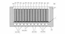
- FIG. 6 shows a vertical cross-sectional view of a battery with heat-conducting members.
- the "longitudinal cross-sectional view” means a view cut vertically from the upper opening inside the battery housing to the bottom.
- the heat source is one or two or more battery cells 30.
- a cooling member is a housing 41 containing the battery cells 30 .
- the heat conducting member 1 described above is interposed between the battery cell 30 and the housing 41 .
- the structure of the battery 40 will be described below.
- the battery 40 is, for example, a battery for an electric vehicle and includes a large number of battery cells 30.
- a suitable example of the battery 40 is a lithium ion battery.
- the battery 40 includes a bottomed housing 41 that is open on one side. Housing 41 is preferably made of aluminum or an aluminum-based alloy.
- the battery cell 30 is arranged inside 44 of the housing 41 . Electrodes (not shown) protrude above the battery cells 30 .
- the plurality of battery cells 30 are preferably brought into close contact with each other in the housing 41 by applying force in a compressing direction using screws or the like from both sides thereof (not shown).
- a bottom portion 42 of the housing 41 is provided with one or more water cooling pipes 43 for flowing cooling water 45 .
- the battery cell 30 is arranged in the housing 41 such that the heat conducting member 1 is sandwiched between the bottom portion 42 (an example of the cooling member) that forms part of the housing 41 .
- the battery cells 30 conduct heat to the housing 41 through the heat conducting member 1 and are effectively removed by water cooling.
- the cooling water 45 may be read as a "cooling medium” or a "coolant”.
- An organic solvent such as liquid nitrogen or ethanol may be used instead of the cooling water 45 .
- the heat conducting member 1 is positioned between the battery cells 30 and the bottom portion 42 (part of the housing 41) including the water cooling pipe 43. , are compressed in the thickness direction of the heat-conducting member 1 . As a result, the heat from the battery cells 30 is easily conducted to the heat conductive film 20 , the bottom portion 42 , the water cooling pipe 43 and the cooling water 45 .
- the battery 40 may be provided with the aforementioned heat conducting members 1a, 1b, 1c, and 1d instead of the heat conducting member 1.
- FIG. 7 shows a cross-sectional view when the battery cell is placed horizontally so that the side surface of the battery cell is in contact with the heat-conducting member, a partially enlarged view thereof, and a partial cross-sectional view when the battery cell expands during charging and discharging. show.
- the battery cells 31 may be arranged such that the sides of the battery cells 31 enclosing the battery liquid in the pouch bag are brought into contact with the heat conductive film 20 of the heat conductive member 1 .
- Battery cells 31 increase in temperature during charging and discharging. If the container of the battery cell 31 itself is made of a highly flexible material, the battery cell 31 may swell, especially at the side surfaces thereof. Even in such a case, as shown in FIG.
- the heat conducting member 1 can be deformed according to the shape of the outer surface of the battery cell 31, so that a high heat dissipation can be maintained during charging and discharging. Further, the side surfaces of the battery cells 31 may be brought into contact with the heat conducting members 1a, 1b, 1c, and 1d instead of the heat conducting member 1.
- FIG. 7 the heat conducting member 1 can be deformed according to the shape of the outer surface of the battery cell 31, so that a high heat dissipation can be maintained during charging and discharging. Further, the side surfaces of the battery cells 31 may be brought into contact with the heat conducting members 1a, 1b, 1c, and 1d instead of the heat conducting member 1.
- the thermally conductive members 1, 1a, 1b, 1c, and 1d are manufactured without interposing an adhesive between the thermally conductive film 20 and the elastic sheet 10, for example.
- an adhesive may be interposed between the heat conductive film 20 and the elastic sheet 10 .
- the adhesive may be of any constituent material, but it is preferable to use an adhesive with excellent heat resistance that can withstand at least a temperature rise due to heat radiation from the battery cells 30 and 31 .
- the elastic sheet 10 is not particularly limited in its shape, and at least on the surface facing the battery cells 30 and 31 and the surface facing the bottom 42, the heat conducting film 20 is exposed at a predetermined interval. Any shape that can hold the film 20 may be, for example, elliptical, trapezoidal, circular, polygonal, or the like.
- the inclined wall 21 is a flat plate in each of the above-described embodiments.
- curved plates are also acceptable.
- the inclination angle of the curved inclined plate with respect to the thickness direction of the heat conducting members 1, 1a, 1b, 1c, and 1d is the angle between the surface in contact with the curved vertex and the thickness direction.
- heat sources include not only the battery cells 30 and 31, but also all heat-generating objects such as circuit boards and electronic device bodies.
- the heat source may be electronic components such as capacitors and IC chips.
- the heat conducting members 1, 1a, 1b, 1c, and 1d may be arranged in structures other than the battery 40, such as electronic devices, home appliances, and power generators.
- the heat-conducting member 1a may be configured by joining the lengthwise ends of the two heat-conducting members 1,1.
Landscapes
- Engineering & Computer Science (AREA)
- Manufacturing & Machinery (AREA)
- Chemical & Material Sciences (AREA)
- Chemical Kinetics & Catalysis (AREA)
- Electrochemistry (AREA)
- General Chemical & Material Sciences (AREA)
- Secondary Cells (AREA)
- Battery Mounting, Suspending (AREA)
Priority Applications (1)
| Application Number | Priority Date | Filing Date | Title |
|---|---|---|---|
| JP2023508666A JP7542131B2 (ja) | 2021-03-25 | 2022-01-14 | 熱伝導部材およびそれを備えるバッテリー |
Applications Claiming Priority (2)
| Application Number | Priority Date | Filing Date | Title |
|---|---|---|---|
| JP2021-052269 | 2021-03-25 | ||
| JP2021052269 | 2021-03-25 |
Publications (1)
| Publication Number | Publication Date |
|---|---|
| WO2022201769A1 true WO2022201769A1 (ja) | 2022-09-29 |
Family
ID=83396752
Family Applications (1)
| Application Number | Title | Priority Date | Filing Date |
|---|---|---|---|
| PCT/JP2022/001020 Ceased WO2022201769A1 (ja) | 2021-03-25 | 2022-01-14 | 熱伝導部材およびそれを備えるバッテリー |
Country Status (2)
| Country | Link |
|---|---|
| JP (1) | JP7542131B2 (https=) |
| WO (1) | WO2022201769A1 (https=) |
Cited By (1)
| Publication number | Priority date | Publication date | Assignee | Title |
|---|---|---|---|---|
| WO2025107844A1 (zh) * | 2023-11-20 | 2025-05-30 | 宁德时代新能源科技股份有限公司 | 热管理部件、电池以及用电装置 |
Citations (5)
| Publication number | Priority date | Publication date | Assignee | Title |
|---|---|---|---|---|
| WO2007125802A1 (ja) * | 2006-04-24 | 2007-11-08 | Sumitomo Electric Industries, Ltd. | 熱伝達部材、凸状構造部材、電子機器、および電気製品 |
| JP2012031242A (ja) * | 2010-07-29 | 2012-02-16 | Nitto Denko Corp | 熱伝導性シート |
| JP2015201534A (ja) * | 2014-04-08 | 2015-11-12 | パナソニックIpマネジメント株式会社 | 熱伝導シートおよびその製造方法 |
| JP2016192520A (ja) * | 2015-03-31 | 2016-11-10 | 太陽誘電株式会社 | 蓄電モジュール |
| JP2019207759A (ja) * | 2018-05-28 | 2019-12-05 | 信越ポリマー株式会社 | 放熱構造体およびバッテリー |
-
2022
- 2022-01-14 JP JP2023508666A patent/JP7542131B2/ja active Active
- 2022-01-14 WO PCT/JP2022/001020 patent/WO2022201769A1/ja not_active Ceased
Patent Citations (5)
| Publication number | Priority date | Publication date | Assignee | Title |
|---|---|---|---|---|
| WO2007125802A1 (ja) * | 2006-04-24 | 2007-11-08 | Sumitomo Electric Industries, Ltd. | 熱伝達部材、凸状構造部材、電子機器、および電気製品 |
| JP2012031242A (ja) * | 2010-07-29 | 2012-02-16 | Nitto Denko Corp | 熱伝導性シート |
| JP2015201534A (ja) * | 2014-04-08 | 2015-11-12 | パナソニックIpマネジメント株式会社 | 熱伝導シートおよびその製造方法 |
| JP2016192520A (ja) * | 2015-03-31 | 2016-11-10 | 太陽誘電株式会社 | 蓄電モジュール |
| JP2019207759A (ja) * | 2018-05-28 | 2019-12-05 | 信越ポリマー株式会社 | 放熱構造体およびバッテリー |
Cited By (1)
| Publication number | Priority date | Publication date | Assignee | Title |
|---|---|---|---|---|
| WO2025107844A1 (zh) * | 2023-11-20 | 2025-05-30 | 宁德时代新能源科技股份有限公司 | 热管理部件、电池以及用电装置 |
Also Published As
| Publication number | Publication date |
|---|---|
| JPWO2022201769A1 (https=) | 2022-09-29 |
| JP7542131B2 (ja) | 2024-08-29 |
Similar Documents
| Publication | Publication Date | Title |
|---|---|---|
| JP7190311B2 (ja) | 放熱構造体およびバッテリー | |
| CN213071222U (zh) | 散热结构体及安装有该散热结构体的蓄电池 | |
| US11495842B2 (en) | Heat dissipating structure and battery provided with the same | |
| CN115398716B (zh) | 散热结构体及具备该散热结构体的电池 | |
| JP7503432B2 (ja) | 放熱構造体およびそれを備えるバッテリー | |
| JP6886543B1 (ja) | 放熱構造体およびそれを備えるバッテリー | |
| TW202030906A (zh) | 散熱結構體以及具備該散熱結構體的電池 | |
| JP2019207759A (ja) | 放熱構造体およびバッテリー | |
| JP2020113387A (ja) | 放熱構造体およびそれを備えるバッテリー | |
| JPWO2019244882A1 (ja) | 放熱構造体、放熱構造体の製造方法およびバッテリー | |
| WO2022201769A1 (ja) | 熱伝導部材およびそれを備えるバッテリー | |
| JP2022175357A (ja) | 熱伝導部材およびそれを備えるバッテリー | |
| JP2021153005A (ja) | 放熱構造体およびバッテリー | |
| JPWO2019230107A1 (ja) | 放熱構造体およびバッテリー | |
| JP7376568B2 (ja) | 放熱構造体シートおよび放熱構造体の製造方法 | |
| JP2021197295A (ja) | 放熱構造体、バッテリーおよび電子機器 | |
| JP7573483B2 (ja) | 熱伝導部材およびそれを備えるバッテリー | |
| JP7534878B2 (ja) | デバイス | |
| JP7598454B2 (ja) | 熱伝導部材、熱伝導部材の製造方法およびバッテリー | |
| WO2023157236A1 (ja) | 熱伝導部材及びその製造方法、並びにバッテリー | |
| JP2021125409A (ja) | 熱伝導構造体およびそれを備えるバッテリー | |
| JP2020009579A (ja) | 放熱構造体およびバッテリー | |
| JP7550092B2 (ja) | 熱伝導ユニットおよびそれを備えるバッテリー | |
| JP2021005582A (ja) | 放熱構造体およびそれを備えるバッテリー | |
| JP2022165443A (ja) | バッテリー |
Legal Events
| Date | Code | Title | Description |
|---|---|---|---|
| 121 | Ep: the epo has been informed by wipo that ep was designated in this application |
Ref document number: 22774574 Country of ref document: EP Kind code of ref document: A1 |
|
| WWE | Wipo information: entry into national phase |
Ref document number: 2023508666 Country of ref document: JP |
|
| NENP | Non-entry into the national phase |
Ref country code: DE |
|
| 122 | Ep: pct application non-entry in european phase |
Ref document number: 22774574 Country of ref document: EP Kind code of ref document: A1 |