WO2022201759A1 - 携帯用研磨機 - Google Patents
携帯用研磨機 Download PDFInfo
- Publication number
- WO2022201759A1 WO2022201759A1 PCT/JP2022/000876 JP2022000876W WO2022201759A1 WO 2022201759 A1 WO2022201759 A1 WO 2022201759A1 JP 2022000876 W JP2022000876 W JP 2022000876W WO 2022201759 A1 WO2022201759 A1 WO 2022201759A1
- Authority
- WO
- WIPO (PCT)
- Prior art keywords
- portable
- grinder
- battery
- dust collection
- sander
- Prior art date
- Legal status (The legal status is an assumption and is not a legal conclusion. Google has not performed a legal analysis and makes no representation as to the accuracy of the status listed.)
- Ceased
Links
Images







Classifications
-
- B—PERFORMING OPERATIONS; TRANSPORTING
- B24—GRINDING; POLISHING
- B24B—MACHINES, DEVICES, OR PROCESSES FOR GRINDING OR POLISHING; DRESSING OR CONDITIONING OF ABRADING SURFACES; FEEDING OF GRINDING, POLISHING, OR LAPPING AGENTS
- B24B47/00—Drives or gearings; Equipment therefor
- B24B47/10—Drives or gearings; Equipment therefor for rotating or reciprocating working-spindles carrying grinding wheels or workpieces
- B24B47/12—Drives or gearings; Equipment therefor for rotating or reciprocating working-spindles carrying grinding wheels or workpieces by mechanical gearing or electric power
-
- B—PERFORMING OPERATIONS; TRANSPORTING
- B25—HAND TOOLS; PORTABLE POWER-DRIVEN TOOLS; MANIPULATORS
- B25F—COMBINATION OR MULTI-PURPOSE TOOLS NOT OTHERWISE PROVIDED FOR; DETAILS OR COMPONENTS OF PORTABLE POWER-DRIVEN TOOLS NOT PARTICULARLY RELATED TO THE OPERATIONS PERFORMED AND NOT OTHERWISE PROVIDED FOR
- B25F5/00—Details or components of portable power-driven tools not particularly related to the operations performed and not otherwise provided for
- B25F5/02—Construction of casings, bodies or handles
-
- B—PERFORMING OPERATIONS; TRANSPORTING
- B24—GRINDING; POLISHING
- B24B—MACHINES, DEVICES, OR PROCESSES FOR GRINDING OR POLISHING; DRESSING OR CONDITIONING OF ABRADING SURFACES; FEEDING OF GRINDING, POLISHING, OR LAPPING AGENTS
- B24B23/00—Portable grinding machines, e.g. hand-guided; Accessories therefor
- B24B23/02—Portable grinding machines, e.g. hand-guided; Accessories therefor with rotating grinding tools; Accessories therefor
- B24B23/03—Portable grinding machines, e.g. hand-guided; Accessories therefor with rotating grinding tools; Accessories therefor the tool being driven in a combined movement
-
- B—PERFORMING OPERATIONS; TRANSPORTING
- B24—GRINDING; POLISHING
- B24B—MACHINES, DEVICES, OR PROCESSES FOR GRINDING OR POLISHING; DRESSING OR CONDITIONING OF ABRADING SURFACES; FEEDING OF GRINDING, POLISHING, OR LAPPING AGENTS
- B24B55/00—Safety devices for grinding or polishing machines; Accessories fitted to grinding or polishing machines for keeping tools or parts of the machine in good working condition
- B24B55/06—Dust extraction equipment on grinding or polishing machines
- B24B55/10—Dust extraction equipment on grinding or polishing machines specially designed for portable grinding machines, e.g. hand-guided
-
- B—PERFORMING OPERATIONS; TRANSPORTING
- B24—GRINDING; POLISHING
- B24B—MACHINES, DEVICES, OR PROCESSES FOR GRINDING OR POLISHING; DRESSING OR CONDITIONING OF ABRADING SURFACES; FEEDING OF GRINDING, POLISHING, OR LAPPING AGENTS
- B24B1/00—Processes of grinding or polishing; Use of auxiliary equipment in connection with such processes
- B24B1/002—Processes of grinding or polishing; Use of auxiliary equipment in connection with such processes using electric current
-
- B—PERFORMING OPERATIONS; TRANSPORTING
- B24—GRINDING; POLISHING
- B24B—MACHINES, DEVICES, OR PROCESSES FOR GRINDING OR POLISHING; DRESSING OR CONDITIONING OF ABRADING SURFACES; FEEDING OF GRINDING, POLISHING, OR LAPPING AGENTS
- B24B23/00—Portable grinding machines, e.g. hand-guided; Accessories therefor
- B24B23/02—Portable grinding machines, e.g. hand-guided; Accessories therefor with rotating grinding tools; Accessories therefor
- B24B23/024—Portable grinding machines, e.g. hand-guided; Accessories therefor with rotating grinding tools; Accessories therefor driven by hands or feet
-
- B—PERFORMING OPERATIONS; TRANSPORTING
- B24—GRINDING; POLISHING
- B24B—MACHINES, DEVICES, OR PROCESSES FOR GRINDING OR POLISHING; DRESSING OR CONDITIONING OF ABRADING SURFACES; FEEDING OF GRINDING, POLISHING, OR LAPPING AGENTS
- B24B47/00—Drives or gearings; Equipment therefor
- B24B47/26—Accessories, e.g. stops
Definitions
- This disclosure relates to a portable polisher.
- a sander configured to orbitally move a polishing pad is known.
- Japanese Patent Application Laid-Open No. 2013-129014 describes a so-called random orbit sander in which a battery mounting portion is formed on the outer surface of the housing, and the power of the battery is supplied to the motor to rotate and eccentrically move the polishing pad. .
- a portable polisher includes a grinder body, a battery holster, and a power cord.
- the grinder main body includes a main housing housing a motor, and a grinder configured to orbitally move by rotation of the motor.
- the battery holster includes a battery mounting portion for detachably mounting a battery.
- the power cord is configured to supply the power of the battery attached to the battery attachment portion to the grinder main body.
- the power cord is configured to connect the grinder body and the battery holster without a housing.
- the relatively heavy battery is attached to the battery attachment portion provided in the battery holster, so the weight of the grinder body can be reduced. Therefore, the operability of the portable polishing machine can be improved. Moreover, since the vibration generated by the orbital motion can be suppressed from being transmitted to the battery mounting portion, the life of the battery mounting portion and the battery mounted in the battery mounting portion can be extended.
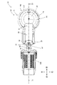
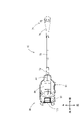
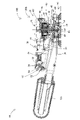
- FIG. 4 is another perspective view of the sander of the first embodiment; It is a top view of the sander main body of 1st Embodiment. It is a longitudinal cross-sectional view of the sander main body of 1st Embodiment. 3 is a top view of a battery holster with a battery attached and a power cord in the first embodiment; FIG. It is a figure which shows the longitudinal cross-sectional view of the battery holster with which the battery was mounted
- FIG. 4 is a diagram showing a simplified configuration of a sander that can be connected to a cleaner
- the power cord may include a first connector that connects with the polisher body.
- the grinder body may comprise a second connector configured to connect with the first connector to supply power of the battery to the motor.
- the portable polishing machine becomes easier compared to a configuration in which the power cord is previously non-detachably connected to the polishing machine main body.
- the battery holster and power cord can be used to connect to other portable polishers that have a second connector.
- the rotating shaft of the motor may extend vertically, and the polishing section may be positioned below the main body housing.
- a main grip portion having a shape that can be gripped by a user may be provided at the upper end portion of the main body housing.
- the main gripping portion and the motor are viewed from above the main gripping portion in the vertical direction (the rotation axis direction)
- the main gripping portion is arranged such that the outer edge of the main gripping portion surrounds the outer edge of the motor. It may be arranged so as to overlap with the motor (so that the outer edge of the main gripping portion is located outside the outer edge of the motor).
- the user can easily perform the polishing work by holding the main grip portion and pressing the polishing machine main body downward, and can effectively reduce the vibration generated by the orbital motion of the polishing portion. can be suppressed.
- the grinder body may further include an auxiliary grip connected to the main grip and extending in a direction intersecting the rotation axis.
- the user can hold the main grip portion with one hand and the auxiliary grip portion with the other hand, and press the grinder main body against the workpiece to perform the grinding operation. , can stabilize the polishing work.
- the grinder body may include a dust collection nozzle configured to discharge dust generated by the grinder grinding the workpiece.
- the dust collection nozzle may be provided below the auxiliary gripper in the vertical direction. When the auxiliary gripping portion and the dust collection nozzle are viewed in the vertical direction from above the auxiliary gripping portion, the dust collection nozzle may be arranged so as to overlap the auxiliary gripping portion.
- the dust collecting nozzle is arranged at a position overlapping the auxiliary gripping portion in the vertical direction, so the size of the grinder main body can be reduced. Further, since the dust collecting nozzle does not interfere with the polishing work, the operability of the portable polishing machine can be improved.
- the second connector may be provided at an end on the side away from the main grip in the extending direction of the auxiliary grip.
- the second connector is arranged in the polishing machine main body at a position away from the polishing section, so that the power cord can be prevented from interfering with the polishing work.
- the power cord is positioned near the user's body, so the power supply is not required. It is possible to further suppress the cord from interfering with the polishing work.
- the rear end portion of the dust collection nozzle may be configured to detachably mount a dust collection container capable of storing the dust.
- the polishing section may include a polishing pad driven by the motor.
- the power cord may be configured so as not to contact the dust container when the portable grinder is in the first state.
- the first state may be a state satisfying (i) to (iv). (i)
- the dust collection container is attached to the dust collection nozzle.
- the polishing pad rests on a flat surface;
- the battery holster and the grinder main body are connected by the power cord.
- the battery holster is arranged so that the weight of the battery holster is not applied to the power cord.
- the portable grinder is configured so that the dust collection container and the power cord do not come into contact with each other (separately) when in the first state. , rubbing (friction) between the dust collection container and the power cord is suppressed. Therefore, the durability of the power cord can be improved, and as a result, the durability of the portable polishing machine can be improved.
- the first state may be a state in which the battery holster further satisfies (a) to (c) below.
- the battery holster is arranged behind the rear end of the dust container.
- the connecting portion of the battery holster to the power cord faces upward.
- the battery holster is arranged above a lower end position of the power cord when the power cord is extended downward.
- the downward extension of the power cord also means a state in which the power cord is not bent and hangs down to a position below the main body of the grinder. When the power cord is extended downward, it can also be said that the power cord is fully extended.
- the first state may include that the battery holster is in an arrangement (orientation) that satisfies (a) to (c), and the portable polishing machine, when in the first state, It is configured so that the dust collection container and the power cord do not come into contact with each other. Therefore, it is effectively suppressed that the dust collection container and the power cord rub against each other due to the vibration generated by the orbital motion.
- the power cord may include a cord body and a cover.
- the cord main body may be configured to electrically connect the battery attached to the battery attachment portion and the grinder main body.
- the cover may be configured to extend rearward from the first connector and cover a portion of the cord body.
- the cover guides the cord body in the extending direction (rearward) of the cover, so that the cord body can be prevented from coming into contact with the dust container. Therefore, the durability of the cord body can be improved.
- “covering part of the cord body” may mean surrounding the outer side (outer circumference, radially outer side) of the cord body in part of the entire length of the cord body.
- the flexibility of the cover may be less than the flexibility of the cord body.
- the cover is configured such that the flexibility of the cover is smaller than the flexibility of the cord body, so that the cord body can be guided in its own extending direction (backward). Therefore, contact of the cord body with the dust container can be further suppressed.
- the cover may be positioned above the dust container when the dust container is attached to the rear end of the dust collection nozzle. Furthermore, the cover may be configured to overlap the dust container by 30% or more in the front-rear direction.
- the cover overlaps the dust container by 30% or more and is positioned above the dust container. Contact with the dust collection container can be effectively suppressed.
- the cover when the state of the portable polishing machine is the first state, the cover is such that a first imaginary plane including the plane intersects with an axis passing through the center of the cover. and may be configured to extend rearwardly and upwardly from the first connector.
- the cord body can be guided rearward and upward by the cover extending rearward and upward. Therefore, it is possible to effectively prevent the cord body from coming into contact with the dust container.
- the cover when the state of the portable polishing machine is the first state, the cover has a first imaginary plane including the plane and the rear end of the polishing pad.
- the angle formed by the second imaginary plane contacting the lower end of the dust collection container may be 5° or more.
- the cover may be configured such that an angle formed by the first virtual plane and the second virtual plane is 15° or less.
- the dust container vibrates or the front end of the polishing part is lifted slightly upward during the polishing operation, the lower end of the dust container is prevented from coming into contact with the workpiece. Therefore, it is possible to suppress deterioration in the durability of the grinder main body to which the dust collection container is connected. In addition, since the dust collection container can be prevented from contacting the workpiece and damaging the workpiece, polishing accuracy can be improved.
- the power cord when the state of the portable polishing machine is the first state, the power cord extends from the intersection of a first imaginary plane including the plane and the cord body.
- An angle formed by a tangent line drawn to the main body and an axis passing through the center of the cover may be 55° or more.
- the power cord may be configured such that an angle formed by the tangent line and the axis line is 90° or less.
- the angle formed by the tangent line and the axis line by setting the angle formed by the tangent line and the axis line to 55° or more, it is possible to effectively prevent the cord body from coming into contact with the dust collection container. Further, by setting the angle formed by the tangent line and the axis to be 90° or less, the cord body does not extend excessively rearward from the grinder body and bends downward at the rear of the grinder body. It is possible to prevent the cord body from interfering with the polishing work. Therefore, the durability of the power cord and the operability of the portable grinder can be improved.
- the cord body extends to a first position including the plane at a first position rearward of the grinder body when the state of the portable grinder is the first state. It may intersect the virtual plane.
- the first position may be a position forward of a position behind the rear end of the grinder main body by the length of the grinder main body in the front-rear direction.
- the cord body bends downward behind the grinder body without excessively extending backward from the grinder body. Therefore, it is possible to prevent the cord main body from interfering with the polishing work, so that the operability of the portable polishing machine can be improved.
- the grinder main body may be configured such that the mass in the front-rear direction is balanced at a predetermined balance point with the dust collection container attached to the rear end. good.
- the balance point may be provided on the auxiliary gripper.
- the front-rear mass (mass moment) of the grinder body to which the dust container is attached is balanced in the auxiliary grip portion extending in the front-rear direction, so that the operability of the portable grinder can be improved.
- the grinder main body has a distance of 0.150 m (meters) or more between the middle point of the length of the dust container in the front-rear direction and the balance point. It may be configured as Further, the grinder main body may be configured such that the distance between the middle point of the length of the dust collection container in the front-rear direction and the balance point is 0.200 m or less.
- the operability of the portable grinder can be improved when the dust collection container is attached to the grinder body.
- the grinder body may be configured such that the distance between the rotating shaft of the motor and the balance point is 0.040 m or more. Further, the grinder main body may be configured such that the distance between the rotating shaft and the balance point is 0.100 m or less.
- the portable grinder is configured such that the moment of mass from the balance point to the axis of rotation of the motor is greater than or equal to 0.20 Nm (Newton-meter). may be Further, the portable grinder may be configured such that the mass moment is 0.50 Nm or less.
- the battery holster may include a hook.
- the hook may be configured to allow the battery holster to be attached to a user.
- the cord body may have a length of 0.80 m or more. Moreover, the length of the cord body may be 2.0 m or less.
- the user can attach the battery holster to a belt or the like with the hook and perform polishing work.
- the length of the cord body is 0.80 m or longer, even if the user stretches his or her arm, it is possible to suppress the cord body from being pulled between the battery holster and the grinder body.
- the length of the cord body is 2.0 m or less, it is possible to prevent the cord body from interfering with the polishing work. Therefore, the operability of the sander 1 can be improved.
- the rear end of the dust collection nozzle may be detachably attached to a hose connected to a suction device that sucks the dust.
- the battery holster may include a mounting portion that can be attached to the suction device.
- the cord body may have a length of 2.0 m or more. Moreover, the length of the cord body may be 6.0 m or less.
- the portable grinder may include the dust collection container.
- the portable polishing machine is configured so that the dust collection container and the power cord do not come into contact with each other when in the first state. Friction with the cord is suppressed. Therefore, the durability of the power cord can be improved, and as a result, the durability of the portable polishing machine can be improved.
- the polisher body may further comprise a controller configured to control rotation of the motor.
- connection between the controller and the motor is made inside the main body of the polishing machine, so the power cord can be made thinner than when the controller is arranged in the battery holster. Therefore, it is possible to further prevent the power cord from interfering with the polishing work.
- the controller may be arranged between the auxiliary gripper and the dust collection nozzle in the vertical direction.
- the grinder body can be made smaller, and the operability of the portable grinder can be improved.
- the battery holster may include a controller configured to control rotation of the motor.
- the size of the grinder body can be reduced compared to a configuration in which the grinder body includes a controller.
- the battery holster may include the battery attached to the battery attachment.
- the battery is attached to the battery holster, so the weight of the grinder body can be reduced. Therefore, the operability of the polishing machine main body can be improved.
- FIG. 1 A sander 1 as an embodiment of a portable grinder will be described below with reference to FIGS. 1 to 6.
- FIG. The sander 1 includes a sander body 10, a battery holster 80, and a power cord 70 connecting the sander body 10 and the battery holster 80.
- - ⁇ Thunder 1 is also called a random orbit sander.
- the sander body 10 includes a housing 20 and a polishing section 50 .
- the housing 20 includes a body housing 21 that houses the motor 40 (see FIG. 4), a controller housing portion 35 that houses the controller 60, and a handle portion 30.
- the polishing unit 50 is arranged on one side of the direction in which the rotation axis A1 of the motor shaft 42 extends, and is configured to perform eccentric motion and rotary motion (random orbit motion) as the motor 40 rotates.
- the handle portion 30 is connected to the body housing 21 on the other side of the extending direction of the motor shaft 42 , which is opposite to the side on which the grinding portion 50 is arranged, and extends in a direction away from the body housing 21 .
- the sander main body 10 is a small sander with a total weight of about 1.0 kg.
- the extending direction of the rotation axis A1 is defined as the vertical direction
- the side where the polishing section 50 is positioned with respect to the main body housing 21 is defined as the lower side
- the opposite side is defined as the upper side.
- the direction in which the handle portion 30 extends is defined as the front-rear direction.
- the side on which the portion 31) is located is defined as the front side
- the opposite side is defined as the rear side.
- a direction orthogonal to the front-rear direction and the up-down direction is defined as the left-right direction.
- the body housing 21 is formed along the vertical direction.
- the outer diameters of the upper end portion 23 and the lower end portion 24 of the body housing 21 are formed larger than the outer diameter of the middle portion 22 of the body housing 21 in the vertical direction.
- a switch 65 for switching between start and stop of the motor 40 is provided at the front end of the upper end portion 23 of the body housing 21 .
- the upper end portion 23 of the body housing 21 has a size and shape suitable for being gripped by the user.
- the upper end portion 23 of the body housing 21 functions as a gripping portion (hereinafter referred to as a main gripping portion 25) of the sander body 10.
- a main gripping portion 25 As shown in FIG.
- the main grip portion 25 is formed in a substantially circular shape when viewed from above.
- the main gripping portion 25 is positioned over the motor 40 so that the outer edge of the main gripping portion 25 surrounds the outer edge of the motor 40 when the main gripping portion 25 and the motor 40 are viewed from above the main gripping portion 25 in the direction of the rotation axis A1. It has a wrapping shape and size.
- the handle portion 30 has a first end portion 31 connected to the main grip portion 25 and extends rearward from the main grip portion 25 along the front-rear direction.
- a second connector 53 which will be described later, is provided at the rear end portion (second end portion 32) of the handle portion 30.
- the width of the handle portion 30 in the left-right direction is formed to be suitable for the user to grip.
- the upper end of the handle portion 30 and the upper end of the main grip portion 25 are formed smooth. The user can grip the main grip portion 25 with one hand and grip the handle portion 30 with the other hand to carry out the polishing work. Also, when the user grips the main grip portion 25 with one hand, the user can also place the vicinity of the wrist of the one hand on the handle portion 30 .
- the handle portion 30 functions as an auxiliary gripping portion for the sander body 10 .
- the controller housing portion 35 is arranged below the handle portion 30 and extends in the front-rear direction.
- the controller housing portion 35 is connected to the lower rear end portion of the intermediate portion 22 of the body housing 21 and extends rearward and upward from the connection portion.
- the rear upper portion of the controller housing portion 35 is connected to the rear lower portion of the handle portion 30 .
- a through hole 38 penetrating through the housing 20 in the left-right direction is formed between the upper front portion of the controller accommodating portion 35 and the lower front portion of the handle portion 30 .
- a dust collection nozzle 39 is arranged on the lower side of the controller housing portion 35 .
- the dust collection nozzle 39 extends in the front-rear direction.
- the dust collection nozzle 39 communicates with the rear end of the lower end portion 24 of the body housing 21 .
- the dust collection nozzle 39 is provided so as to incline upward and rearward from a connection point with the lower end portion 24 of the main body housing 21 .
- a rear end portion 391 of the dust collection nozzle 39 protrudes rearward from the handle portion 30 .
- the dust collection pack 105 is connected to the rear end portion 391 of the dust collection nozzle 39 . Dust generated by the polishing operation of the workpiece is discharged to the dust collection pack 105 through the holes provided in the polishing pad 51 and the lower end portion 24 of the main body housing 21 and the dust collection nozzle 39 .
- the controller housing portion 35 when the handle portion 30 , the controller housing portion 35 , and the dust collection nozzle 39 are viewed from above the handle portion 30 in the vertical direction, the controller housing portion 35 and the dust collection nozzle 39 overlap the handle portion 30 . Placed in a wrap.
- the controller housing portion 35 is arranged between the handle portion 30 and the dust collection nozzle 39 in the vertical direction and formed slightly larger than the handle portion 30 and the dust collection nozzle 39 in the horizontal direction.
- the motor 40 housed in the body housing 21 includes a motor body 41 having a stator and a rotor, and a motor shaft 42 extending vertically.
- the motor shaft 42 is supported by bearings 44 and 45 held in the body housing 21 .
- a fan 47 is orthogonally fixed to the lower end of the motor shaft 42 via bolts 46 extending in the vertical direction.
- the fan 47 is arranged at the lower end 24 of the body housing 21 .
- a bearing box 49 is further eccentrically assembled to the fan 47 via a bearing 48 provided eccentrically to the rotation axis A1 of the motor shaft 42 .
- the polishing section 50 has a polishing pad 51 .
- the polishing pad 51 is formed in a disc shape and can be attached with sanding paper.
- the polishing pad 51 is coupled to the bearing box 49 by bolts 56 extending vertically.
- the bottom surface of the polishing pad 51 functions as a polishing surface for polishing the workpiece when the sander body 10 is used.
- the drive shaft of the polishing unit 50 is also the rotation shaft A1 of the motor 40 . In the sander body 10, when the motor 40 rotates, the rotation is transmitted to the bearing box 49 via the bearing 48 eccentric to the motor shaft 42, so that the bearing box 49 and the polishing pad 51 perform eccentric and rotational motions. .
- a second connector 53 is provided at the second end portion 32 of the handle portion 30 .
- the second connector 53 is provided at the second end portion 32 of the handle portion 30 on the inclined wall 34 that is inclined from the upper end of the handle portion 30 to the lower rear portion.
- the second connector 53 includes a terminal portion 54 including positive and negative power supply terminals and communication terminals, and a cylindrical wall 55 surrounding the terminal portion 54 and projecting obliquely upward from the inclined wall 34 .
- a first connector 71 of a power cord 70 to be described later is detachably connected to the second connector 53 .
- the controller 60 housed in the controller housing portion 35 is electrically connected to the second connector 53 and the motor 40 .
- the controller 60 includes various circuits and is configured to control the operation of the motor 40 by controlling the power supplied from the battery 101 attached to the battery holster 80 to the motor 40 .
- an adapter housing portion 36 is provided on the right wall of the rear portion of the handle portion 30 .
- the adapter housing portion 36 is a recessed portion of the side wall at the rear end of the handle portion 30 .
- a wireless communication adapter 61 is inserted into and attached to the adapter accommodating portion 36 .
- Wireless communication adapter 61 is electrically connected to controller 60 .
- the wireless communication adapter 61 wirelessly communicates with other incidental equipment.
- the incidental equipment is, for example, a dust collector that can be connected to the dust collection nozzle 39 and sucks chips. By wireless communication, the start-up operation and stop operation of the incidental equipment are interlocked with the start-up operation and stop operation of the sander main body 10 .
- the wireless communication adapter 61 is associated (paired) to enable wireless communication with the wireless communication adapter 61 attached in advance to the incidental equipment. Pairing is performed by pressing both the button of the wireless communication adapter 61 and the button of the wireless communication adapter 61 of the incidental equipment.
- the button is, for example, a button for activating the WPS function or the AOSS function.
- the battery holster 80 includes a block-shaped battery holster body portion 81 , a battery mounting portion 85 and a hook 86 .
- the battery holster 80 includes a battery holster side connection portion 87 to which one end 72 of the power cord 70 is physically connected.
- the battery 101 attached to the battery attachment portion 85 is placed face down, the battery holster side connection portion 87 is arranged on the front side, and the power cord 70 connected to the battery holster side connection portion 87 is placed forward and backward.
- the battery holster 80 and power cord 70 are shown when oriented.
- the battery mounting portion 85 is provided in an opening recess (not shown) formed in the lower portion of the battery holster body portion 81 .
- the battery mounting portion 85 includes a pair of left and right slide rails extending in the front-rear direction, positive and negative power supply terminals, and communication terminals.
- the pair of slide rails is configured to be engageable with a pair of rail receiving portions of battery 101 .
- the pair of rail receiving portions are engaged with the slide rails, and the battery 101 is mounted on the battery. Attached to portion 85 .
- the positive and negative power terminals and communication terminals of the battery mounting portion 85 are electrically connected to the positive and negative power terminals and communication terminals of the battery 101, respectively.
- the hook 86 protrudes upward and forward from the upper rear portion of the battery holster body portion 81 .
- Hook 86 is formed to allow battery holster 80 to be attached to the user's clothing or belt.
- the hook 86 is also a mounting portion for mounting the battery holster 80 on the user.
- the battery holster side connection portion 87 is a portion protruding from the front end of the battery holster body portion 81 .
- the battery holster side connection portion 87 is physically connected to one end 72 of the power cord 70 .
- the weight of the battery holster 80 of this embodiment when the battery 101 is attached is approximately 0.7 kg to 1.0 kg. Therefore, the weight ratio of the battery holster 80 with the battery 101 attached to the sander main body 10 is relatively large.
- the power cord 70 electrically connects the sander body 10 and the battery holster 80 and physically connects (couples) the sander body 10 and the battery holster 80 without a housing. It can also be said that the power cord 70 is not covered with a housing.
- the power cord 70 has a cord body 73 and a first connector 71 .
- the cord body 73 is configured by covering a power line for supplying power from the battery 101 to the sander body 10 with a protective tube.
- the tube is made of polyvinyl chloride resin (PVC).
- the tube may be made of other synthetic resins such as rubber or rubber mixtures.
- the power line is electrically connected to a power terminal provided on the battery mounting portion 85 .
- the cord body 73 may have a signal line for the controller 60 to detect an abnormality in the battery 101 in addition to the power line.
- the first connector 71 is provided at the end opposite to the one end 72 of the cord body 73 .
- the first connector 71 includes a terminal portion 74 connected to the power line of the cord body 73 and a cylindrical engaging portion 75 provided around the terminal portion 74 .
- the periphery of the first connector 71 of the cord body 73 is covered with a substantially conical cylindrical cover 76 whose outer diameter widens toward the first connector 71 .
- the first connector 71 is detachably attached to the second connector 53 of the sander body 10 .
- the engaging portion 75 of the first connector 71 is fitted into the tubular wall 55 of the second connector 53 , the terminal portions 74 of the first connector 71 and the second connector 53 are connected to each other. and the terminal portion 54 of the second connector 53 are electrically connected.
- the battery 101 is attached to the battery attachment portion 85 of the battery holster 80, and when the user turns on the switch 65 of the sander main body 10, the power of the battery 101 is supplied through the power cord 70. can be supplied to the sander main body 10.
- the power of the battery 101 is supplied through the power terminal of the battery mounting portion 85, the power line of the cord body 73, the terminal portion 74 of the first connector 71, and the terminal portion 54 of the second connector 53.
- the controller 60 is connected to the motor 40 by lead wires (power supply wire and signal wire) and controls power supplied to the motor 40 .
- the polishing unit 50 polishing pad 51
- the polishing unit 50 is eccentrically and rotationally moved (random orbital motion), enabling polishing of the workpiece.
- the sander body 10 is provided with the sanding part 50 configured to orbitally move.
- the relatively heavy battery 101 is mounted in the battery mounting portion 85 of the battery holster 80, and the sander main body 10 and the battery holster 80 are connected by the power cord 70 without the housing. Therefore, since the battery 101 is not attached to the sander body 10, the weight of the sander body 10 during sanding work can be reduced compared to a configuration in which the battery 101 is attached to the sander body. Therefore, the operability of the sander main body 10 and the sander 1 can be improved.
- the weight of the sander main body 10 is less than that of the structure in which the sander main body includes a battery.
- the sander main body 10 can be easily operated even when performing sanding work while supporting the main body 10 . In addition, it is possible to reduce the burden on the user during the polishing work.
- vibration may occur more easily in exchange for improved performance such as improved polishing accuracy compared to a sander that does not orbitally move.
- the battery 101 is not attached to the sander main body 10 , so vibrations generated by the orbital motion are less likely to be transmitted to the battery attachment portion 85 and the battery 101 . Therefore, the life of the battery mounting portion 85 and the battery 101 can be extended.
- the user can attach the battery holster 80 to the user with the hook 86 and perform the polishing work.
- the battery holster 80 and the sander main body 10 are connected by the power cord 70 without the housing 20 interposed therebetween. Therefore, the degree of freedom of the positional relationship between the battery holster 80 and the sander body 10 can be increased compared to a configuration in which the battery holster 80 and the sander body 10 are connected by a housing.
- the main body housing 21 of the sander main body 10 accommodates the motor 40 , and the polishing section 50 is provided below the main body housing 21 .
- a main grip portion 25 is provided at the upper end of the body housing 21 .
- the main gripping portion 25 and the motor 40 are viewed from above the main gripping portion 25 in the direction of the rotation axis A1, the main gripping portion 25 is arranged to overlap the motor 40 so that the outer edge of the main gripping portion 25 surrounds the outer edge of the motor 40. there is Therefore, by holding the main grip part 25 and pressing the sander main body 10 downward, the user can easily perform the sanding work, and can effectively cope with the vibration generated by the orbital motion of the sanding part 50. be able to.
- the sander body 10 also includes a handle portion 30 extending rearward from the main grip portion 25 . Therefore, the user can grip the main grip portion 25 with one hand, grip the handle portion 30 with the other hand, and press the sander main body 10 against the workpiece to carry out the sanding work. polishing work can be performed.
- the user when the user grips the main grip portion 25 with one hand, the user can also place the vicinity of the wrist of the one hand on the handle portion 30 .
- the main grip portion 25 when the main grip portion 25 is gripped with one hand and the polishing work is performed, the vicinity of the user's wrist can be supported by the handle portion 30, so that the burden on the user's hand and wrist can be reduced.
- the sander main body 10 is provided with a second connector 53 configured so that the first connector 71 of the power cord 70 can be attached and detached. Therefore, the power cord 70 and the battery holster 80 can be carried or stored separately from the sander main body 10. Therefore, compared to a configuration in which the power cord 70 is previously non-detachably connected to the sander main body, The sander 1 as a whole can be easily handled. Also, the battery holster 80 and power cord 70 can be used to connect to other portable polishers having the second connector 53 .
- the second connector 53 is provided at the rear end portion (second end portion 32) of the handle portion 30 extending rearward from the main grip portion 25. Therefore, since the second connector 53 is arranged in the sander main body 10 at a position away from the sanding portion 50, it is possible to prevent the power cord 70 from interfering with the sanding work. Further, when the handle portion 30 is arranged on the user side, the polishing portion 50 is arranged on the far side from the user, and the battery holster 80 is attached to the user by the hook 86 and the polishing work is performed, the power cord 70 is placed near the user's body. , the power cord 70 can be prevented from interfering with the polishing work.
- the sander main body 10 is provided with a dust collection nozzle 39, and the dust collection nozzle 39 overlaps the handle portion 30 when the handle portion 30 and the dust collection nozzle 39 are viewed from above the handle portion 30 in the vertical direction. placed in position. Therefore, by providing the dust collection nozzle 39, the sander body 10 can be prevented from becoming large, and the sander body 10 can be made compact.
- the sander main body 10 includes the controller 60, compared to the case where the battery holster includes the controller 60 and the lead wire connecting the controller 60 and the motor 40 is arranged in the cord body 73 of the power cord 70,
- the cord body 73 can be configured thin. Therefore, it is possible to further prevent the cord body 73 from interfering with the polishing work.
- the controller 60 is housed in a portion (controller housing portion 35) between the handle portion 30 of the housing 20 and the dust collection nozzle 39 in the vertical direction. Therefore, the sander main body 10 can be configured compactly. Further, since the controller accommodating portion 35 does not interfere with the sanding work, the operability of the sander 1 can be improved.
- FIGS. 7 to 9 show the sander 1 in a state (hereinafter also referred to as the first state) that satisfies (i) to (iv) below.
- the sander 1 of this embodiment is configured so that the dust collection pack 105 and the power cord 70 do not come into contact with each other in the first state.
- a dust collection pack 105 is connected to the dust collection nozzle 39 .
- the polishing pad 51 is placed on a flat surface.
- the plane is a plane (horizontal plane) perpendicular to the vertical direction.
- the plane may be, for example, a working surface.
- 8 and 9 show a virtual plane (first virtual plane P1) including the plane.
- the battery holster 80 and the sander main body 10 are connected by the power cord 70 . In the examples shown in FIGS. 7 to 9, the first connector 71 and the second connector 53 are connected.
- the battery holster 80 is arranged so that the weight of the battery holster 80 is not applied to the power cord 70 . In the examples shown in FIGS.
- the battery holster 80 is placed on a predetermined plane (not shown) below the first imaginary plane P1.
- Condition (iv) can be satisfied when the battery holster 80 is attached to the user's belt or the like with the hook 86 and the user performs sanding work using the sander body 10 (sander 1).
- the first state further includes a state in which the sander 1 satisfies the following (a) to (c).
- the following (a) to (c) mainly relate to the state (posture, arrangement) of the battery holster 80.
- FIG. 9 shows a virtual plane (fourth virtual plane P4) passing through the rear end 112 of the dust collection pack 105 and perpendicular to the front-rear direction.
- the battery holster 80 is located behind the fourth imaginary plane P4.
- the connecting portion of the battery holster 80 to the power cord 70 faces upward.
- the portion of the battery holster 80 battery holster side connection portion 87
- the battery holster 80 is arranged above the lower end position of the power cord 70 when the power cord 70 is extended downward.
- FIG. 9 shows a virtual plane (fifth virtual plane P5) that passes through the lower end (one end 72) of the power cord 70 when the cord body 73 is extended downward and is perpendicular to the vertical direction.
- the battery holster 80 is located above the fifth imaginary plane P5.
- the downward extension of the power cord 70 also means that the cord body 73 hangs down below the sander body 10 while the cord body 73 is not bent.
- the downward extension of the cord body 73 can also be said to be a state in which the cord body 73 is fully extended. Even if the weight of the battery holster 80 is not applied to the cord body 73 , the cord body can be extended downward depending on the positional relationship between the battery holster 80 and the sander body 10 .
- the sander 1 of this embodiment is configured so that the dust collection pack 105 and the power cord 70 do not come into contact with each other (separately) when in the first state described above. Therefore, even if the dust collection pack 105 vibrates due to the vibration generated by the orbital motion, the dust collection pack 105 and the power cord 70 are prevented from rubbing against each other. As a result, wear of the power cord 70 is suppressed.
- the sander main body 10 of the present embodiment has a handle portion 30 extending in the front-rear direction, and the motor 40 and the sanding portion 50, which are vibration sources, are arranged on the front side of the handle portion 30.
- the dust collection pack 105 is connected to the rear end portion 391 of the dust collection nozzle 39 that protrudes rearward from the handle portion 30 . Therefore, when the user grips the main grip part 25 and presses the grinding part 50 against the workpiece to perform grinding work, the dust collection pack 105 may vibrate relatively greatly.
- the dust collection pack 105 and the power cord 70 are configured so as not to come into contact with each other, wear of the power cord 70 is suppressed. Therefore, the durability of the sander 1 can be improved.
- the dust collection pack 105 includes a mounting portion 106 and a dust collection portion 107 .
- the mounting portion 106 is detachably attached to the rear end portion 391 of the dust collection nozzle 39 .
- the dust collecting portion 107 is connected to the mounting portion 106 and extends rearward from the mounting portion 106 .
- the dust collection portion 107 is configured to store dust discharged from the dust collection nozzle 39 and to discharge air sent from the dust collection nozzle 39 .
- the dust collector 107 includes an outer case having an air discharge hole, and a storage section provided inside the outer case and capable of storing dust.
- the dust collection pack 105 is made of synthetic resin. In other embodiments, the dust collection pack 105 may be formed by a cloth or paper container.
- each part of the sander 1 that contributes to improving the durability and operability of the sander 1 will be described below.
- the configuration of the power cord 70 and the sander main body 10, and the positional relationship between the power cord 70, the sander main body 10, and the dust collection pack 105 will be described in detail.
- the cover 76 of the power cord 70 extends rearward from the first connector 71 and partially covers the cord body 73 .
- the cover 76 is arranged outside (periphery, radially outside) of the cord body 73 over part of the entire length of the cord body 73 .
- the cover 76 is configured such that the flexibility of the cover 76 is smaller than the flexibility of the cord body 73 (protective tube that covers the power line). With such a configuration, the cover 76 guides the cord body 73 rearward in its extending direction, and prevents the cord body 73 from coming into contact with the dust collection pack 105 .
- the cover 76 is arranged above (immediately above) the dust collection pack 105 and away from the dust collection pack 105 .
- a front end 761 of the cover 76 is positioned substantially at the same position as or slightly ahead of the front end 111 of the dust collection pack 105 in the front-rear direction.
- a rear end 762 of the cover 76 is located above (directly above) the dust collection pack 105 .
- the axis A2 passing through the center (radial center) of the cover 76 substantially coincides with the axis (not shown) passing through the center of the first connector 71 .
- the cover 76 is configured to overlap the dust collection pack 105 by 30% or more in the front-rear direction.
- the length L1 shown in FIG. 8 is the length from the front end 111 to the rear end 112 of the dust collection pack 105 (the length in the front-rear direction, the total length), and the length L2 is the distance between the dust collection pack 105 and the cover 76. This is the length of the overlapping portion.
- length L2 is approximately half of length L1. That is, the cover 76 overlaps the dust pack 105 by approximately 50%.
- the cover 76 extends rearward and upward from the first connector 71 when the sander 1 is in the first state. At this time, as shown in FIG. 8, the axis A2 of the cover 76 intersects with the first imaginary plane P1. In other words, the angle R1 between the axis A2 of the cover 76 and the first imaginary plane P1 is greater than zero. With such a configuration, the cover 76 can guide the cord body 73 rearward and upward.
- the angle R2 formed between the upper surface 113 of the dust collection pack 105 and the first virtual plane P1 is smaller than the angle R1 formed between the axis A2 of the cover 76 and the first virtual plane P1. That is, the rearward and upward inclination of the cover 76 is greater than the inclination of the dust collection pack 105 .
- the cover 76 can effectively prevent the cord body 73 from coming into contact with the upper surface 113 of the dust collection pack while guiding the cord body 73 rearward and upward.
- the angle R2 is shown as an angle formed by the upper surface 113 and the third virtual plane P3 parallel to the first virtual plane P1 for convenience of illustration.
- FIG. 8 shows an angle R3 formed between a tangent line A3 drawn from the intersection point N1 between the first imaginary plane P1 and the cord body 73 to the cord body 73 and the axis A2 of the cover 76.
- the angle R3 is preferably 55° or more. By setting the angle R3 to 55° or more, the cord body 73 passes behind the dust pack 105 without contacting the dust pack 105 and bends downward. Therefore, abrasion of the cord body 73 can be suppressed.
- the angle R3 is preferably 90° or less.
- the angle R3 By setting the angle R3 to 90° or less, it is possible to suppress downward bending of the cord body 73 at a position excessively far rearward from the rear end 112 of the dust collection pack 105 . Therefore, it is possible to prevent the cord body 73 from interfering with the polishing work. That is, by configuring the power cord 70 so that the angle R3 is 55° or more and 90° or less, it is possible to improve the durability of the power cord 70 (cord body 73) and improve the operability of the sander 1. .
- FIG. 9 shows the length (longitudinal length, total length) L3 of the sander main body 10 .
- the position N1 where the cord body 73 intersects the first virtual plane P1 is forward of the rear end of the sander body 10 by the length L3 of the sander body 10 (position N2).
- FIG. 8 shows a second imaginary plane P2 that contacts the lower end (lower surface 114) of the dust collection pack 105 and passes through the rear end 511 of the polishing pad 51.
- An angle R4 between the first virtual plane P1 and the second virtual plane P2 is preferably 5° or more. With such a configuration, even if the dust collection pack 105 vibrates or the front end of the polishing unit 50 is slightly lifted during the polishing operation, the lower end (lower surface 114) of the dust collection pack 105 contacts the workpiece. hard to do Also, the angle R4 is preferably 15° or less. With such a configuration, the dust collection pack 105 and the cord body 73 can be spaced apart in the vertical direction to some extent.
- the length of the cord body 73 is preferably 0.80 m (meter) or longer.
- the battery holster 80 of the sander 1 is provided with the hook 86, and the user can attach the battery holster 80 to a belt or the like with the hook 86 to perform the sanding work. Further, in the sander 1, the cord body 73 guided rearward and upward by the cover 76 is bent downward at a predetermined position in the front-rear direction, and as shown in FIG. and intersects the first virtual plane P1.
- the length of the cord body 73 is preferably 2.0 m or less. By setting the length of the cord body 73 to 2.0 m or longer, it is possible to suppress the cord body 73 from interfering with the polishing work. Therefore, the operability of the sander 1 can be improved.
- the sander body 10 of the present embodiment has a mass (mass moment) in the front-rear direction at a predetermined position (balance point C1, see FIG. 9) of the handle portion 30 with the dust collection pack 105 attached to the dust collection nozzle 39. are configured to be balanced.
- FIG. 9 shows the balance point C1, the center point C2 of the dust collection pack 105 in the front-rear direction, and the center point C3 of the controller 60 in the front-rear direction. 9 also shows a distance L4 between the balance point C1 and the center point C2 of the dust collection pack 105, a distance L5 between the balance point C1 and the rotation axis A1 of the motor 40, and a center point between the balance point C1 and the controller 60. A distance L6 to C3 is shown.
- the distance L4 is preferably 0.150 m or more. Also, the distance L4 is preferably 0.200 m or less.
- the distance L5 is preferably 0.040 m or more. Also, the distance L5 is preferably 0.100 m or less. With this configuration, it is possible to prevent the distance between the balance point C1 and the rotation axis A1 of the motor 40 from becoming too large while making the length of the sander body 10 easy to grip. Therefore, the operability of the sander 1 can be improved.
- the mass moment from the balance point C1 to the rotation axis A1 of the motor is preferably 0.20 Nm (Newton-meter) or more. Also, the mass moment is preferably 0.50 Nm or less.
- the mass moment from the balance point C1 to the center point C3 is within the above range, it is possible to prevent the moment in front of the balance point C1 from becoming too large. Therefore, the sander main body 10 suitable for carrying can be provided.
- each part in the sander 1 of this embodiment is as follows. However, the following numerical values are an example, and as long as the sander 1 is provided with a power cord 70 that physically and electrically connects the sander body 10 and the battery holster 80 without a housing, other configurations (shapes) may be adopted.
- Distance L4 from balance point C1 to point C2 0.185m (meter)
- Distance L5 from balance point C1 to rotation axis A1 of motor 40 0.050 m
- Distance L6 from balance point C1 to point C3 0.048m Mass of controller 60: 0.100 kg (kg)
- Mass of dust collection pack 105 0.130 kg Mass of dust collection pack 105 when storage section is filled with dust: 0.185 kg Mass of front part from balance point C1 in sander body 10: 0.780 kg Mass moment in the portion from the balance point C1 to the rotation axis A1 of the motor 40: 0.38 Nm (Newton-meter)
- FIG. 10 Although the power cord 70 and battery holster 80 of the sander 1A are not shown in FIGS. 10 and 11, the sander 1A of this embodiment includes the power cord 70 and battery holster 80 described in the first embodiment.
- symbol is used about the structure similar to the above-mentioned embodiment, and the detailed description is abbreviate
- the main difference between the sander 1A of this embodiment and the sander 1 of the first embodiment is that the sander main body 10A is configured as an orbital sander.
- the polishing portion 50A of the sander main body 10A includes a polishing pad 51A and a base 52A provided on the polishing pad 51A.
- the base 52A and the housing 20 are connected by a foot (not shown). The foot regulates rotation of the base 52A.
- the polishing pad 51A is formed in a substantially triangular shape with an acute front end when viewed in the vertical direction.
- the fan 47 is further eccentrically assembled with a bearing box 49A via bearings 481A and 482A provided eccentrically with respect to the rotation axis A1 of the motor shaft 42 in the vertical direction.
- Other configurations of the sander 1A of the second embodiment are the same as those of the sander 1 of the above-described first embodiment, so description thereof will be omitted.
- the sander 1A of the second embodiment has the same configuration as the sander 1 of the first embodiment except that the rotational movement of the sanding portion 50A of the sander main body 10A is restricted. Therefore, the sander 1A of the second embodiment also has the same effects as the sander 1 of the first embodiment.
- the sander 1A of the present embodiment has a mass of 0.700 kg in the front portion from the balance point C1, and a mass moment of 0.34 Nm (newton meters) in the portion from the balance point C1 to the rotation axis A1 of the motor 40. is.
- the configuration of the power cord 70 and the sander body 10A, the positional relationship among the power cord 70, the sander body 10A, and the dust collection pack 105, and the moment (mass moment) of the sander 1A are the same as in the first embodiment. Therefore, the description is omitted.
- FIG. 13 A sander 1B according to the third embodiment will be described with reference to FIGS. 12 and 13.
- FIG. The main difference between the sander 1B of the present embodiment and the sander 1 of the first embodiment is that the housing 20B of the sander main body 10B does not accommodate the controller 60, and the battery holster body 81B of the battery holster 80B does not include the controller 60.
- the battery holster body portion 81B is formed vertically larger than the battery holster body portion 81 of the first embodiment, and accommodates the controller 60 above the battery mounting portion 85 .
- the cord main body 73B includes a controller 60 housed in the battery holster main body 81B, a lead wire (power wire and signal wire) connecting the motor 40 of the sander main body 10B, and a controller for operating the switch 65.
- a signal line for transmission to the is inserted.
- the battery 101 is attached to the battery attachment portion 85 of the battery holster 80B, and when the user turns on the switch 65 of the sander body 10B, the power of the battery 101 is transferred to the battery holster body 81B. It is controlled by the controller 60 housed therein and supplied to the motor 40 of the sander main body 10B via the power cord 70B. Since other configurations of the sander 1A are the same as those of the sander 1 of the first embodiment, description thereof is omitted.
- the controller 60 is provided in the battery holster 80B connected to the sander main body 10B and the power cord 70B. Therefore, it is possible to suppress transmission of the vibration generated by the orbital motion of the polishing unit 50 during the polishing operation to the controller 60 .
- the controller 60 is not housed in the housing 20 of the sander body 10B, the sander body 10B can be made compact.
- the sander 1B of the third embodiment has the same configuration as the sander 1 of the first embodiment, except that the battery holster 80B has a controller 60. Therefore, the sander 1B of the third embodiment also has the same effect as the first embodiment.
- a sander 1C according to the fourth embodiment will be described with reference to FIG.
- a hose 201 is attached to the rear end portion 391 of the dust collection nozzle 39 , and the sander body 10 is connected to the cleaner 200 via the hose 201 .
- the battery holster 80 ⁇ /b>C has an attachment portion 81 ⁇ /b>C to which the battery holster can be attached to the cleaner 200 .
- the attachment portion 81C may be, for example, a hook that can be engaged with the cleaner 200. As shown in FIG. Dust generated by the polishing work is sucked (stored) in the cleaner 200 through the hose 201 by operating the cleaner 200 .
- the cord body 73 and the hose 201 are bound with a band 205 .
- the length of the cord body 73 is preferably 2.0 m or longer. Also, the length of the cord body 73 is preferably 6.0 m or less.
- Battery 101 is an example of a "battery.”
- the battery mounting portion 85 is an example of a “battery mounting portion.”
- Battery holsters 80, 80B, 80C are examples of “battery holsters.”
- the cord bodies 73 and 73B and the power cords 70 and 70B are examples of "power cords.”
- the first connector 71 and the second connector 53 are examples of the "first connector” and the "second connector", respectively.
- the upper end 23 is an example of an “upper end”.
- the main gripping portion 25 is an example of a “main gripping portion”.
- the handle part 30 is an example of an "auxiliary grip part”.
- the dust collection nozzle 39 is an example of a "dust collection nozzle.”
- the second end 32 is an example of "the end on the side remote from the main gripping portion”.
- Controller 60 is an example of a “controller.”
- the rear end 391 is an example of a "rear end”.
- the dust collection pack 105 is an example of a "dust collection container.”
- the trailing edge 112 is an example of a "dust bin trailing edge.”
- the battery holster side connection portion 87 is an example of a "connection portion with a power cord in the battery holster".
- One end 72 of the power cords 70, 70B is an example of "the lower end of the power cord when the power cord is extended downward".
- the polishing pads 51 and 51A are examples of "polishing pads”.
- the code bodies 73 and 73B are examples of "code bodies”.
- Cover 76 is an example of a “cover.”
- the axis A2 is an example of "the axis passing through the center of the cover”.
- the tangent line A3 is an example of a "tangent line”.
- the first virtual plane P1 and the second virtual plane P2 are examples of "first virtual plane” and “second virtual plane", respectively.
- Hook 86 is an example of a "hook”.
- the mounting portion 81C is an example of a "mounting portion”.
- Cleaner 200 is an example of a "suction device.”
- Hose 201 is an example of a "hose.”
- the first connectors 71 of the power cords 70, 70B may be non-removably connected to the sander bodies 10, 10A, 10B. Also, the power cords 70, 70B may be provided with a connector on the one end 72 side, and the connector and the battery holsters 80, 80B may be configured to be detachable.
- housings 20, 20B of the sander bodies 10, 10A, 10B is not limited to the shapes of the above embodiments.
- housings 20 and 20B may not have handle portion 30 .
- the second connector 53 may be provided at other locations on the housings 20, 20B. For example, it may be provided at the first end portion 31 of the handle portion 30 or the rear portion of the controller housing portion 35 .
- the battery holsters 80, 80B may be provided with other mounting parts, such as belts, for mounting the battery holsters 80, 80B on the user instead of or in addition to the hooks 86.
- the rotating shaft A1 of the motor 40 was also the driving shaft of the polishing units 50 and 50A.
- the rotating shaft A1 of the motor 40 and the driving shafts of the polishing units 50 and 50A do not have to coincide.
- the motor shaft may be arranged in the longitudinal direction
- the drive shaft of the polishing section may be arranged in the vertical direction
- the rotational power of the motor may be transmitted to the drive shaft of the polishing section by a known transmission mechanism.
- the present disclosure is not limited to the above-described embodiments, and can be implemented in various configurations without departing from the scope of the present disclosure.
- the technical features in the embodiments corresponding to the technical features in the respective modes described in the Summary of the Invention column may be used to solve some or all of the above problems, or Substitutions and combinations may be made as appropriate to achieve part or all.
- the technical features are not described as essential in this specification, they can be deleted as appropriate.
- 1, 1A, 1B, 1C sander, 10, 10A, 10B: sander main body, 20: housing, 21: main body housing, 22: intermediate part, 23: upper end part, 24: lower end part, 25: main grip part, 30 : handle portion, 31: first end portion, 32: second end portion, 34: inclined wall, 35: controller accommodating portion, 36: adapter accommodating portion, 38: through hole, 39: dust collecting nozzle, 40: motor, 41: Motor body, 42: Motor shaft, 44, 45, 48: Bearing, 46: Bolt, 47: Fan, 49: Bearing box, 49A: Bearing box, 50: Polishing part, 50A: Polishing part, 51: Polishing pad , 51A: polishing pad, 53: second connector, 54: terminal portion, 55: cylindrical wall, 56: bolt, 60: controller, 61: wireless communication adapter, 65: switch, 70: power cord, 70B: power cord, 71: first connector, 72: one end, 73: cord body, 73B: cord body, 74: terminal portion, 75:
Landscapes
- Engineering & Computer Science (AREA)
- Mechanical Engineering (AREA)
- Grinding-Machine Dressing And Accessory Apparatuses (AREA)
- Finish Polishing, Edge Sharpening, And Grinding By Specific Grinding Devices (AREA)
- Portable Power Tools In General (AREA)
- Cleaning In General (AREA)
Abstract
Description
以下、図1から図6までを参照して、携帯用研磨機の一実施形態としてのサンダ1について説明する。サンダ1は、サンダ本体10と、バッテリホルスタ80と、サンダ本体10とバッテリホルスタ80とを接続する電源コード70とを備える。サンダ1は、ランダムオービットサンダとも呼ばれる。
(ii)研磨パッド51が平面に載置されている。
なお、平面は、上下方向に直交する面(水平面)である。平面は、例えば、加工面であってもよい。図8及び図9には、当該平面を含む、仮想的な平面(第1仮想平面P1)が図示されている。
(iii)バッテリホルスタ80とサンダ本体10とが、電源コード70によって接続されている。
図7から図9に示す例では、第1コネクタ71と第2コネクタ53とが接続されている。
(iv)バッテリホルスタ80の自重が電源コード70に加わらないように、バッテリホルスタ80が配置されている。
図8及び図9に示す例では、バッテリホルスタ80が、第1仮想平面P1よりも下方にある所定の面(不図示)に載置されている。
(iv)の条件は、バッテリホルスタ80がフック86によってユーザのベルト等に装着され、ユーザがサンダ本体10(サンダ1)を用いた研磨作業を行う場合に、満たされ得る。
図9には、集塵パック105の後端112を通り、前後方向に直交する仮想的な平面(第4仮想平面P4)が示されている。本実施形態では、バッテリホルスタ80は、第4仮想平面P4よりも後方に位置している。
(b)バッテリホルスタ80における電源コード70との接続部分が、上方に向けられている。
図9に示す例では、バッテリホルスタ80(バッテリホルスタ側接続部87)における、電源コード70の一端72と接続される部分が、上方に向けられている。
(c)バッテリホルスタ80は、電源コード70が下方に伸長されたときの電源コード70の下端位置よりも、上方に配置されている。
図9には、コード本体73が下方に伸長されたときにおける電源コード70の下端(一端72)を通り、上下方向に直交する仮想的な平面(第5仮想平面P5)が示されている。図9に示す例では、バッテリホルスタ80は、第5仮想平面P5よりも上方に位置している。なお、電源コード70(コード本体73)が下方に伸長されるとは、コード本体73に撓みがない状態で、コード本体73が、サンダ本体10よりも下方まで垂れ下がった状態でもある。コード本体73が下方に伸長されるとは、コード本体73が伸びきった状態ということもできる。バッテリホルスタ80の自重がコード本体73に加わっていなくとも、バッテリホルスタ80とサンダ本体10との配置関係によっては、コード本体が下方に伸長され得る。
釣り合い点C1からモータ40の回転軸A1までの距離L5:0.050m
釣り合い点C1から点C3までの距離L6:0.048m
コントローラ60の質量:0.100kg(キログラム)
集塵パック105の質量:0.130kg
貯留部が粉塵で満たされた場合における、集塵パック105の質量:0.185kg
サンダ本体10における、釣り合い点C1から前部分の質量:0.780kg
釣り合い点C1からモータ40の回転軸A1までの部分における、質量モーメント:0.38Nm(ニュートン・メートル)
図10及び図11を用いて、第2実施形態のサンダ1Aについて説明する。図10及び図11には、サンダ1Aの電源コード70とバッテリホルスタ80とは現れていないが、本実施形態のサンダ1Aは、第1実施形態で説明した電源コード70及びバッテリホルスタ80を備える。なお、以下では、上述の実施形態と同様の構成については同じ符号を用い、その詳細な説明を省略する。
図12及び図13を用いて、第3実施形態のサンダ1Bについて説明する。本実施形態のサンダ1Bと第1実施形態のサンダ1とが異なる主な点は、サンダ本体10Bのハウジング20Bがコントローラ60を収容しておらず、バッテリホルスタ80Bのバッテリホルスタ本体部81Bがコントローラ60を収容している点である。図13に示すように、バッテリホルスタ本体部81Bは、第1実施形態のバッテリホルスタ本体部81よりも上下方向に大きく形成されており、バッテリ装着部85の上部にコントローラ60を収容している。本実施形態では、コード本体73B内には、バッテリホルスタ本体部81Bに収容されたコントローラ60と、サンダ本体10Bのモータ40とのリード線(電源線及び信号線)と、スイッチ65の操作をコントローラに伝達する信号線とが挿通されている。
図14を用いて、第4実施形態のサンダ1Cについて説明する。本実施形態では、集塵ノズル39の後端部391に、ホース201が装着されており、サンダ本体10は、ホース201を介してクリーナー200に接続されている。また、本実施形態では、バッテリホルスタ80Cは、クリーナー200にバッテリホルスタを取付可能な取付部81Cを備えている。取付部81Cは、例えば、クリーナー200に係合可能なフックであってもよい。研磨作業で生じた粉塵は、クリーナー200を動作させることで、ホース201を介してクリーナー200に吸引(貯留)される。コード本体73とホース201とは、バンド205で結束されている。コード本体73の長さは、2.0m以上であることが好ましい。また、コード本体73の長さは、6.0m以下であることが好ましい。このように構成することで、サンダ本体10とクリーナー200との間でコード本体73が引っ張られることや、コード本体73が研磨作業の妨げになることを抑制できる。したがって、サンダ1Cの操作性を向上させることができる。
上記実施形態の各構成要素と本開示の技術の各構成要素の対応関係を以下に示す。但し、実施形態の各構成要素は単なる一例であって、本開示の技術の各構成要素を限定するものではない。
サンダ1、1A、1B、1Cは、「携帯用研磨機」の一例である。
サンダ本体10、10A、10Bは、「研磨機本体」の一例である。
電源コード70、70Bは、「電源コード」の一例である。
モータ40は、「モータ」の一例である。
本体ハウジング21、ハウジング20、20Bは、「本体ハウジング」の一例である。
研磨部50、50Aは、「研磨部」の一例である。
バッテリ101は、「バッテリ」の一例である。
バッテリ装着部85は、「バッテリ装着部」の一例である。
バッテリホルスタ80、80B、80Cは、「バッテリホルスタ」の一例である。
コード本体73、73B、電源コード70、70Bは、「電源コード」の一例である。
第1コネクタ71、第2コネクタ53は、それぞれ、「第1コネクタ」、「第2コネクタ」の一例である。
上端部23は、「上端部」の一例である。
主把持部25は、「主把持部」の一例である。
ハンドル部30は、「補助把持部」の一例である。
集塵ノズル39は、「集塵ノズル」の一例である。
第2端部32は、「主把持部から離れる側の端部」の一例である。
コントローラ60は、「コントローラ」の一例である。
後端部391は、「後端部」の一例である。
集塵パック105は、「集塵容器」の一例である。
後端112は、「集塵容器の後端」の一例である。
バッテリホルスタ側接続部87は、「バッテリホルスタにおける電源コードとの接続部」の一例である。
電源コード70、70Bの一端72は、「電源コードが下方に伸長されたときの電源コードの下端」の一例である。
研磨パッド51、51Aは、「研磨パッド」の一例である。
コード本体73、73Bは、「コード本体」の一例である。
カバー76は、「カバー」の一例である。
軸線A2は、「カバーの中心を通る軸線」の一例である。
接線A3は、「接線」の一例である。
第1仮想平面P1、第2仮想平面P2は、夫々、「第1仮想平面」、「第2仮想平面」の一例である。
フック86は、「フック」の一例である。
取付部81Cは、「取付部」の一例である。
クリーナー200は、「吸引装置」の一例である。
ホース201は、「ホース」の一例である。
電源コード70、70Bの第1コネクタ71は、サンダ本体10、10A、10Bに取り外し不能に接続されていてもよい。また、電源コード70、70Bは、一端72側にコネクタを備えていてもよく、当該コネクタとバッテリホルスタ80、80Bとが着脱可能に構成されていてもよい。
Claims (26)
- 携帯用研磨機であって、
モータを収容する本体ハウジングと、前記モータの回転によりオービタル運動するように構成された研磨部と、を備える研磨機本体と、
バッテリを装着可能なバッテリ装着部を備えるバッテリホルスタと、
前記バッテリ装着部に装着された前記バッテリの電力を前記研磨機本体へ供給するように構成され、前記研磨機本体と前記バッテリホルスタとをハウジングを介さずに接続する、電源コードと、を備える、
携帯用研磨機。 - 請求項1に記載の携帯用研磨機であって、
前記電源コードは、前記研磨機本体と接続する第1コネクタを備え、
前記研磨機本体は、前記第1コネクタと接続して前記バッテリの電力を前記モータへ供給するように構成された第2コネクタを備え、
前記第1コネクタは、前記第2コネクタに着脱可能に構成されている、携帯用研磨機。 - 請求項1又は請求項2に記載の携帯用研磨機であって、
前記モータの回転軸は上下方向に延在し、前記研磨部は前記本体ハウジングに対して下側に位置しており、
前記本体ハウジングの上端部は、ユーザが把持可能な主把持部として構成されており、
前記主把持部の上方から前記上下方向に前記主把持部及び前記モータをみたときに、前記主把持部は、前記主把持部の外縁が前記モータの外縁を囲うように前記モータとオーバーラップして配置されている、携帯用研磨機。 - 請求項3に記載の携帯用研磨機であって、
前記研磨機本体は、前記主把持部に接続されて前記回転軸に交差する方向に延在する補助把持部を更に備える、携帯用研磨機。 - 請求項4に記載の携帯用研磨機であって、
前記研磨機本体は、前記上下方向において前記補助把持部の下方に設けられ、前記研磨部が加工材を研磨することで生成された粉塵を排出するように構成された集塵ノズルを備え、
前記補助把持部の上方から、前記上下方向に前記補助把持部と前記集塵ノズルとをみたときに、前記集塵ノズルは、前記補助把持部とオーバーラップして配置されている、携帯用研磨機。 - 請求項2に間接的に従属する請求項4又は請求項5に記載の携帯用研磨機であって、
前記第2コネクタは、前記補助把持部の延在方向のうち、前記主把持部から離れる側の端部に設けられている、携帯用研磨機。 - 請求項5に従属する請求項6記載の携帯用研磨機であって、
前記補助把持部の延在方向を前後方向とし、前記補助把持部が前記主把持部とが接続する側を前側、その反対側を後側と定義した場合に、前記集塵ノズルの後端部は、前記粉塵を貯留可能な集塵容器を着脱可能に装着するように構成されており、
前記研磨部は、前記モータにより駆動される研磨パッドを含み、
前記電源コードは、前記携帯用研磨機の状態が、(i)前記集塵ノズルに前記集塵容器が装着され、(ii)前記研磨パッドが平面に載置され、(iii)前記バッテリホルスタと前記研磨機本体とが前記電源コードによって接続され、(iv)前記バッテリホルスタの自重が前記電源コードに加わらないように前記バッテリホルスタが配置された、第1状態である場合に、前記集塵容器に接触しないように構成されている、携帯用研磨機。 - 請求項7に記載の携帯用研磨機であって、
前記第1状態において、(a)前記バッテリホルスタは、前記集塵容器の後端よりも後方に配置され、(b)前記バッテリホルスタにおける前記電源コードとの接続部は、上方に向けられ、(c)前記バッテリホルスタは、前記電源コードが下方に伸長されたときの前記電源コードの下端位置よりも、上方に配置される、携帯用研磨機。 - 請求項7又は請求項8に記載の携帯用研磨機であって、
前記電源コードは、前記バッテリと前記研磨機本体とを導通するコード本体と、前記第1コネクタから後方に延出され前記コード本体の一部を覆うカバーと、を含む、携帯用研磨機。 - 請求項9に記載の携帯用研磨機であって、
前記カバーの可撓性は、前記コード本体の可撓性よりも小さい、携帯用研磨機。 - 請求項9又は請求項10に記載の携帯用研磨機であって、
前記集塵ノズルの前記後端部に前記集塵容器が装着された場合に、前記カバーは、前記集塵容器の上方に位置し、かつ、前記前後方向において前記集塵容器に対し30%以上オーバーラップするように構成されている、携帯用研磨機。 - 請求項9から請求項11までのいずれか一項に記載の携帯用研磨機であって、
前記カバーは、前記携帯用研磨機の状態が前記第1状態である場合に、前記平面を含む第1仮想平面と前記カバーの中心を通る軸線とが交差し、前記第1コネクタから後方かつ上方へ延在するように構成されている、携帯用研磨機。 - 請求項9から請求項12までのいずれか一項に記載の携帯用研磨機であって、
前記カバーは、前記携帯用研磨機の状態が前記第1状態である場合に、前記平面を含む第1仮想平面と、前記研磨パッドの後端を通り前記集塵容器の下端に接触する第2仮想平面と、の成す角が、5°以上15°以下となるように構成されている、携帯用研磨機。 - 請求項9から請求項13までのいずれか一項に記載の携帯用研磨機であって、
前記電源コードは、前記携帯用研磨機の状態が前記第1状態である場合に、前記平面を含む第1仮想平面と前記コード本体との交点から前記コード本体へ引いた接線と、前記カバーの中心を通る軸線と、の成す角が、55°以上90°以下となるように構成されている、帯用研磨機。 - 請求項9から請求項14のいずれか一項に記載の携帯用研磨機であって、
前記コード本体は、前記携帯用研磨機の状態が前記第1状態である場合に、前記研磨機本体よりも後方の第1位置で前記平面を含む第1仮想平面と交差し、
前記第1位置は、前記研磨機本体の後端から前記研磨機本体の前記前後方向における長さと同じ長さ分後方の位置よりも前方の位置である、携帯用研磨機。 - 請求項7から請求項15までのいずれか一項に記載の携帯用研磨機であって、
前記研磨機本体は、前記後端部に前記集塵容器が装着された状態で前記前後方向における質量が所定の釣り合い点で釣り合うように構成されており、
前記釣り合い点は、前記補助把持部に設けられている、携帯用研磨機。 - 請求項16に記載の携帯用研磨機であって、
前記研磨機本体は、前記集塵容器の前記前後方向における長さの中間点と、前記釣り合い点と、の距離が、0.150m以上、かつ、0.200m以下になるように構成されている、携帯用研磨機。 - 請求項16又は請求項17に記載の携帯用研磨機であって、
前記研磨機本体は、前記モータの前記回転軸と前記釣り合い点との距離が、0.040m以上、かつ、0.100m以下になるように構成されている、携帯用研磨機。 - 請求項16から請求項18までのいずれか一項に記載の携帯用研磨機であって、
前記携帯用研磨機は、前記釣り合い点から前記モータの前記回転軸までの部分の質量モーメントが、0.20Nm以上、かつ、0.50Nm以下になるように構成されている、携帯用研磨機。 - 請求項9から請求項19までのいずれか一項に記載の携帯用研磨機であって、
前記バッテリホルスタはフックを含み、
前記コード本体の長さは、0.80m以上、かつ、2.0m以下である、携帯用研磨機。 - 請求項9から請求項20までのいずれか一項に記載の携帯用研磨機であって、
前記集塵ノズルの前記後端部は、前記粉塵を吸引する吸引装置に接続されるホースに着脱可能に構成されており、
前記バッテリホルスタは、前記吸引装置に取付け可能な取付部を備えており、
前記コード本体の長さは、2.0m以上、かつ、6.0m以下である、携帯用研磨機。 - 請求項8から請求項20までのいずれか一項に記載の携帯用研磨機であって、更に、
前記携帯用研磨機は、前記集塵容器を含む、携帯用研磨機。 - 請求項1から請求項22までのいずれか一項に記載の携帯用研磨機であって、
前記研磨機本体は、更に、前記モータの回転を制御するように構成されたコントローラを備える、携帯用研磨機。 - 請求項6に直接又は間接的に従属する請求項23に記載の携帯用研磨機であって、
前記コントローラは、前記上下方向において前記補助把持部と前記集塵ノズルとの間に配置されている、携帯用研磨機。 - 請求項1から請求項23までのいずれか一項に記載の携帯用研磨機であって、
前記バッテリホルスタは、前記モータの回転を制御するように構成されたコントローラを備える、携帯用研磨機。 - 請求項1から請求項25までのいずれか一項に記載の携帯用研磨機であって、
前記バッテリホルスタは、前記バッテリ装着部に装着される前記バッテリを備える、携帯用研磨機。
Priority Applications (5)
| Application Number | Priority Date | Filing Date | Title |
|---|---|---|---|
| US18/281,331 US20240157506A1 (en) | 2021-03-26 | 2022-01-13 | Portable abrading machine |
| CN202280022572.2A CN117015455A (zh) | 2021-03-26 | 2022-01-13 | 便携式研磨机 |
| JP2023508660A JP7591127B2 (ja) | 2021-03-26 | 2022-01-13 | 携帯用研磨機 |
| DE112022001226.9T DE112022001226T5 (de) | 2021-03-26 | 2022-01-13 | Tragbares schleifgerät |
| JP2024198704A JP2025013706A (ja) | 2021-03-26 | 2024-11-14 | 携帯用研磨機 |
Applications Claiming Priority (2)
| Application Number | Priority Date | Filing Date | Title |
|---|---|---|---|
| JP2021052804 | 2021-03-26 | ||
| JP2021-052804 | 2021-03-26 |
Publications (1)
| Publication Number | Publication Date |
|---|---|
| WO2022201759A1 true WO2022201759A1 (ja) | 2022-09-29 |
Family
ID=83396849
Family Applications (1)
| Application Number | Title | Priority Date | Filing Date |
|---|---|---|---|
| PCT/JP2022/000876 Ceased WO2022201759A1 (ja) | 2021-03-26 | 2022-01-13 | 携帯用研磨機 |
Country Status (5)
| Country | Link |
|---|---|
| US (1) | US20240157506A1 (ja) |
| JP (2) | JP7591127B2 (ja) |
| CN (1) | CN117015455A (ja) |
| DE (1) | DE112022001226T5 (ja) |
| WO (1) | WO2022201759A1 (ja) |
Cited By (1)
| Publication number | Priority date | Publication date | Assignee | Title |
|---|---|---|---|---|
| DE102023134320A1 (de) * | 2023-12-07 | 2025-06-12 | Andreas Stihl Ag & Co. Kg | Benutzertragbare Batteriepack-Aufnahmeeinrichtung und benutzertragbares Bearbeitungssystem |
Citations (14)
| Publication number | Priority date | Publication date | Assignee | Title |
|---|---|---|---|---|
| JPS62148169A (ja) * | 1985-12-23 | 1987-07-02 | 松下電工株式会社 | 電気機器の電池収納ケ−ス |
| JPH0362783U (ja) * | 1989-10-20 | 1991-06-19 | ||
| JPH07150760A (ja) * | 1993-07-30 | 1995-06-13 | Tobishima Corp | シーリング面の下地形成装置及び方法 |
| JPH08336778A (ja) * | 1995-06-09 | 1996-12-24 | Hitachi Koki Co Ltd | 携帯用トリマ |
| JP2001162508A (ja) * | 1999-12-07 | 2001-06-19 | Makita Corp | サンダ |
| JP2005246949A (ja) * | 2004-02-04 | 2005-09-15 | Kowa Kenshiyou Kk | 集塵機能付き工具および携帯用集塵機 |
| JP2005279891A (ja) * | 2004-03-30 | 2005-10-13 | Hitachi Koki Co Ltd | サンダ |
| JP2009166147A (ja) * | 2008-01-11 | 2009-07-30 | Ryobi Ltd | バッテリー付き電動工具 |
| JP2009285786A (ja) * | 2008-05-29 | 2009-12-10 | Makita Corp | ダストボックス及び電動工具 |
| JP2017104949A (ja) * | 2015-12-10 | 2017-06-15 | リョービ株式会社 | 電動工具及び電動工具用のカバー |
| JP2017185615A (ja) * | 2015-10-15 | 2017-10-12 | 株式会社マキタ | ポリッシャ |
| JP2017202537A (ja) * | 2016-05-10 | 2017-11-16 | リョービ株式会社 | バッテリアダプタ装置 |
| WO2020161025A1 (de) * | 2019-02-07 | 2020-08-13 | Festool Gmbh | Werkzeugmaschine mit einer wuchteinrichtung |
| EP3700048A1 (en) * | 2019-02-19 | 2020-08-26 | Techtronic Cordless GP | Adapter for multiple electric devices to achieve synchronized operations |
Family Cites Families (3)
| Publication number | Priority date | Publication date | Assignee | Title |
|---|---|---|---|---|
| FI129765B (sv) * | 2007-03-21 | 2022-08-15 | Oy Kwh Mirka Ab | Kompakt elektrisk slipmaskin |
| JP6667236B2 (ja) * | 2015-09-10 | 2020-03-18 | 株式会社マキタ | グラインダ、カバー及びカバーセット |
| JP7249797B2 (ja) * | 2019-02-08 | 2023-03-31 | 株式会社マキタ | 携帯用加工機 |
-
2022
- 2022-01-13 CN CN202280022572.2A patent/CN117015455A/zh active Pending
- 2022-01-13 JP JP2023508660A patent/JP7591127B2/ja active Active
- 2022-01-13 DE DE112022001226.9T patent/DE112022001226T5/de active Pending
- 2022-01-13 US US18/281,331 patent/US20240157506A1/en active Pending
- 2022-01-13 WO PCT/JP2022/000876 patent/WO2022201759A1/ja not_active Ceased
-
2024
- 2024-11-14 JP JP2024198704A patent/JP2025013706A/ja active Pending
Patent Citations (14)
| Publication number | Priority date | Publication date | Assignee | Title |
|---|---|---|---|---|
| JPS62148169A (ja) * | 1985-12-23 | 1987-07-02 | 松下電工株式会社 | 電気機器の電池収納ケ−ス |
| JPH0362783U (ja) * | 1989-10-20 | 1991-06-19 | ||
| JPH07150760A (ja) * | 1993-07-30 | 1995-06-13 | Tobishima Corp | シーリング面の下地形成装置及び方法 |
| JPH08336778A (ja) * | 1995-06-09 | 1996-12-24 | Hitachi Koki Co Ltd | 携帯用トリマ |
| JP2001162508A (ja) * | 1999-12-07 | 2001-06-19 | Makita Corp | サンダ |
| JP2005246949A (ja) * | 2004-02-04 | 2005-09-15 | Kowa Kenshiyou Kk | 集塵機能付き工具および携帯用集塵機 |
| JP2005279891A (ja) * | 2004-03-30 | 2005-10-13 | Hitachi Koki Co Ltd | サンダ |
| JP2009166147A (ja) * | 2008-01-11 | 2009-07-30 | Ryobi Ltd | バッテリー付き電動工具 |
| JP2009285786A (ja) * | 2008-05-29 | 2009-12-10 | Makita Corp | ダストボックス及び電動工具 |
| JP2017185615A (ja) * | 2015-10-15 | 2017-10-12 | 株式会社マキタ | ポリッシャ |
| JP2017104949A (ja) * | 2015-12-10 | 2017-06-15 | リョービ株式会社 | 電動工具及び電動工具用のカバー |
| JP2017202537A (ja) * | 2016-05-10 | 2017-11-16 | リョービ株式会社 | バッテリアダプタ装置 |
| WO2020161025A1 (de) * | 2019-02-07 | 2020-08-13 | Festool Gmbh | Werkzeugmaschine mit einer wuchteinrichtung |
| EP3700048A1 (en) * | 2019-02-19 | 2020-08-26 | Techtronic Cordless GP | Adapter for multiple electric devices to achieve synchronized operations |
Cited By (2)
| Publication number | Priority date | Publication date | Assignee | Title |
|---|---|---|---|---|
| DE102023134320A1 (de) * | 2023-12-07 | 2025-06-12 | Andreas Stihl Ag & Co. Kg | Benutzertragbare Batteriepack-Aufnahmeeinrichtung und benutzertragbares Bearbeitungssystem |
| DE102023134320B4 (de) * | 2023-12-07 | 2025-06-18 | Andreas Stihl Ag & Co. Kg | Benutzertragbare Batteriepack-Aufnahmeeinrichtung und benutzertragbares Bearbeitungssystem |
Also Published As
| Publication number | Publication date |
|---|---|
| US20240157506A1 (en) | 2024-05-16 |
| JPWO2022201759A1 (ja) | 2022-09-29 |
| JP2025013706A (ja) | 2025-01-24 |
| JP7591127B2 (ja) | 2024-11-27 |
| CN117015455A (zh) | 2023-11-07 |
| DE112022001226T5 (de) | 2023-12-21 |
Similar Documents
| Publication | Publication Date | Title |
|---|---|---|
| CN108527092B (zh) | 可双手操作的砂光机 | |
| RU2590426C2 (ru) | Технологическая машина, прежде всего электрическая технологическая машина | |
| WO2014119133A1 (ja) | 研削工具 | |
| JP7762576B2 (ja) | 電動作業機 | |
| JP2025013706A (ja) | 携帯用研磨機 | |
| JP2023101211A (ja) | 作業機 | |
| US20250229375A1 (en) | Orbital polisher | |
| JP7262209B2 (ja) | 携帯用研磨機 | |
| CN113941951B (zh) | 便携式研磨机 | |
| JP2025013706A5 (ja) | ||
| US11872682B2 (en) | Portable power tool | |
| JP5854818B2 (ja) | サンダ | |
| JP7600012B2 (ja) | 携帯用研磨機 | |
| US7364498B1 (en) | Double armed finishing tool for tubing materials | |
| CN216463774U (zh) | 打磨工具 | |
| JP5105161B2 (ja) | 電動工具 | |
| JP7863002B2 (ja) | 作業機 | |
| US20250073839A1 (en) | Sander | |
| CN119589534A (zh) | 打磨工具以及砂带机 | |
| JP2026053024A (ja) | ディスクグラインダ | |
| CN118493259A (zh) | 动力工具用的集尘袋以及动力工具 | |
| JP2022086132A (ja) | 集塵アタッチメント及び電動工具 | |
| JP2009078080A (ja) | 電気掃除機 | |
| GB2590704A (en) | Pole sander |
Legal Events
| Date | Code | Title | Description |
|---|---|---|---|
| 121 | Ep: the epo has been informed by wipo that ep was designated in this application |
Ref document number: 22774564 Country of ref document: EP Kind code of ref document: A1 |
|
| WWE | Wipo information: entry into national phase |
Ref document number: 2023508660 Country of ref document: JP |
|
| WWE | Wipo information: entry into national phase |
Ref document number: 18281331 Country of ref document: US |
|
| WWE | Wipo information: entry into national phase |
Ref document number: 202280022572.2 Country of ref document: CN |
|
| WWE | Wipo information: entry into national phase |
Ref document number: 112022001226 Country of ref document: DE |
|
| 122 | Ep: pct application non-entry in european phase |
Ref document number: 22774564 Country of ref document: EP Kind code of ref document: A1 |