WO2022201672A1 - 収容ケースおよびその収容ケースに電池パックを収容する方法 - Google Patents
収容ケースおよびその収容ケースに電池パックを収容する方法 Download PDFInfo
- Publication number
- WO2022201672A1 WO2022201672A1 PCT/JP2021/046482 JP2021046482W WO2022201672A1 WO 2022201672 A1 WO2022201672 A1 WO 2022201672A1 JP 2021046482 W JP2021046482 W JP 2021046482W WO 2022201672 A1 WO2022201672 A1 WO 2022201672A1
- Authority
- WO
- WIPO (PCT)
- Prior art keywords
- battery pack
- fixing
- housing
- bracket
- fixing component
- Prior art date
- Legal status (The legal status is an assumption and is not a legal conclusion. Google has not performed a legal analysis and makes no representation as to the accuracy of the status listed.)
- Ceased
Links
Images








Classifications
-
- H—ELECTRICITY
- H01—ELECTRIC ELEMENTS
- H01M—PROCESSES OR MEANS, e.g. BATTERIES, FOR THE DIRECT CONVERSION OF CHEMICAL ENERGY INTO ELECTRICAL ENERGY
- H01M50/00—Constructional details or processes of manufacture of the non-active parts of electrochemical cells other than fuel cells, e.g. hybrid cells
- H01M50/20—Mountings; Secondary casings or frames; Racks, modules or packs; Suspension devices; Shock absorbers; Transport or carrying devices; Holders
- H01M50/204—Racks, modules or packs for multiple batteries or multiple cells
- H01M50/207—Racks, modules or packs for multiple batteries or multiple cells characterised by their shape
- H01M50/213—Racks, modules or packs for multiple batteries or multiple cells characterised by their shape adapted for cells having curved cross-section, e.g. round or elliptic
-
- H—ELECTRICITY
- H01—ELECTRIC ELEMENTS
- H01M—PROCESSES OR MEANS, e.g. BATTERIES, FOR THE DIRECT CONVERSION OF CHEMICAL ENERGY INTO ELECTRICAL ENERGY
- H01M50/00—Constructional details or processes of manufacture of the non-active parts of electrochemical cells other than fuel cells, e.g. hybrid cells
- H01M50/20—Mountings; Secondary casings or frames; Racks, modules or packs; Suspension devices; Shock absorbers; Transport or carrying devices; Holders
- H01M50/218—Mountings; Secondary casings or frames; Racks, modules or packs; Suspension devices; Shock absorbers; Transport or carrying devices; Holders characterised by the material
- H01M50/22—Mountings; Secondary casings or frames; Racks, modules or packs; Suspension devices; Shock absorbers; Transport or carrying devices; Holders characterised by the material of the casings or racks
- H01M50/227—Organic material
-
- H—ELECTRICITY
- H01—ELECTRIC ELEMENTS
- H01M—PROCESSES OR MEANS, e.g. BATTERIES, FOR THE DIRECT CONVERSION OF CHEMICAL ENERGY INTO ELECTRICAL ENERGY
- H01M50/00—Constructional details or processes of manufacture of the non-active parts of electrochemical cells other than fuel cells, e.g. hybrid cells
- H01M50/20—Mountings; Secondary casings or frames; Racks, modules or packs; Suspension devices; Shock absorbers; Transport or carrying devices; Holders
- H01M50/262—Mountings; Secondary casings or frames; Racks, modules or packs; Suspension devices; Shock absorbers; Transport or carrying devices; Holders with fastening means, e.g. locks
-
- H—ELECTRICITY
- H01—ELECTRIC ELEMENTS
- H01M—PROCESSES OR MEANS, e.g. BATTERIES, FOR THE DIRECT CONVERSION OF CHEMICAL ENERGY INTO ELECTRICAL ENERGY
- H01M50/00—Constructional details or processes of manufacture of the non-active parts of electrochemical cells other than fuel cells, e.g. hybrid cells
- H01M50/20—Mountings; Secondary casings or frames; Racks, modules or packs; Suspension devices; Shock absorbers; Transport or carrying devices; Holders
- H01M50/271—Lids or covers for the racks or secondary casings
Definitions
- the present invention relates to a storage case and a method for storing a battery pack in the storage case, and more particularly to a storage case for storing a battery pack configured by combining a plurality of secondary batteries, and a storage case for storing at least one battery pack. Regarding methods of containment.
- a battery unit consisting of a large number of rechargeable secondary batteries is used for various purposes, such as an uninterruptible power supply that backs up the power supply during a power failure, an emergency power supply, or a power storage device for a power generation system using renewable energy. in use.
- Such a battery unit usually has at least one battery pack housed in a box-shaped housing case.
- an L-shaped fixing part is arranged on the mounting surface of the housing case on which the batteries are mounted to form a partition wall.
- a structure is known in which a partition wall defines a mounting position of a battery pack in a housing case and fixes the battery pack to the housing case.
- the present disclosure has been made in view of such problems, and the object thereof is to improve the mounting position accuracy of the battery pack by integrating the fixing parts with the housing case, and reduce the number of parts and the manufacturing process.
- a storage case is a storage case that stores a battery pack configured by combining a plurality of batteries, and includes a storage portion and a bracket, and the storage portion holds the battery pack.
- a mounting surface at least one side surface rising from the mounting surface, and a first fixing component installed on the side surface, the first fixing component having a flat surface and two curved surfaces,
- the flat surface is substantially perpendicular to the side surface and extends substantially parallel to the mounting surface, and each of the two curved surfaces extends from the flat surface toward the mounting surface to form a V-shape.
- the bracket is fixed to the mounting surface of the housing portion, and the bracket has a side wall surface extending substantially parallel to the side surface of the housing portion and a second fixing portion installed on the side wall surface.
- a component wherein the second fixed component has a flat surface and two curved surfaces, the flat surface being substantially perpendicular to the side wall surface and extending substantially parallel to the mounting surface;
- Each of the two curved surfaces extends from the flat surface toward the mounting surface and faces each other in an inverted V shape. It is held by both flat surfaces of the second fixing part, held by the side surface of the receiving part and the side wall surface of the bracket, supported by the two curved surfaces of the first fixing part, and is supported by the two curved surfaces of the second fixing part. It is characterized by being supported by one bending surface.
- a method for accommodating a battery pack according to one aspect of the present disclosure in a storage case according to one aspect of the present disclosure wherein the battery pack includes a bottom surface that contacts a mounting surface when stored in the storage case, and a bottom surface. a step of abutting one end of the upper surface on one side of the battery pack against the flat surface of the first fixing component in a state in which the bottom surface of the battery pack is slanted with respect to the mounting surface; 1. Rotate the battery pack using the portion of the fixing part that is in contact with the flat surface as a fulcrum until the bottom surface of the battery pack is approximately parallel to the mounting surface, and place one side of the battery pack.
- the battery pack is held by the flat surface of the second fixing component and the curved surface of the second fixing component by pressing the battery pack against the mounting surface of the containing portion by means of the step of abutting the side of the battery pack against the side surface of the containing portion and by pressing the battery pack toward the mounting surface of the containing portion with the bracket. pressing against the mounting surface to fix the bracket to the mounting surface with a fixing means.
- the manufacturing method for housing a battery pack in the housing case of the present disclosure the mounting position accuracy of the battery pack is improved by integrating the fixing parts with the housing case, and the number of parts and the number of manufacturing steps are reduced.
- the housing case for housing a battery pack and a method for housing the battery pack in the housing case which can be manufactured at a lower manufacturing cost.
- FIG. 1 is a perspective view of a housing case housing a battery pack of one embodiment.
- FIG. 2 is an exploded perspective view of a housing case that houses the battery pack of one embodiment.
- FIG. 3 is a perspective view in which a cover plate is added to the storage case of one embodiment.
- FIG. 4 is a perspective view of a battery pack of one embodiment.
- 5A is a perspective view of the internal structure of the battery pack of FIG. 4.
- FIG. 5B is an exploded perspective view of the battery pack of FIG. 5A.
- 5C is a perspective view of the internal structure of the battery pack of FIG. 4.
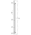
- FIG. FIG. 6 is a perspective view of a housing portion of the housing case of one embodiment. 7 is an enlarged view of the first fixing component of FIG. 6; FIG. FIG.
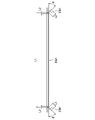
- FIG. 8 is a front view of a first fixation component of one embodiment.
- 9 is an enlarged view of the first fixing component of FIG. 6;
- FIG. FIG. 10 is a perspective view of a cushioning material and a film attached to the first fixing component of one embodiment.
- FIG. 11 is a perspective view including a cross section of the battery pack housed in the housing case of one embodiment.
- FIG. 12 is a perspective view of a bracket of the containment case of one embodiment. 13 is an enlarged view of the bracket of FIG. 11;
- FIG. FIG. 14 is a front view of a second fixation component of one embodiment;
- FIG. 15 is a perspective view of a bracket of the containment case of one embodiment. 16 is an enlarged view of FIG. 3.
- FIG. 17 is a plan view of the bracket and cover plate of one embodiment.
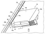
- FIG. 18 is a perspective view of a storage case and battery pack in one manufacturing step of one embodiment.
- FIG. 1 shows a perspective view of a battery unit including a housing case 1 housing a battery pack 10 of one embodiment.
- the housing case 1 includes a housing portion 20 , a bracket 30 and a control circuit 50 .
- the bracket 30 is fixed to the housing portion 20 .
- FIG. 2 shows an exploded perspective view of the housing case 1 with the bracket 30 removed from the state shown in FIG.
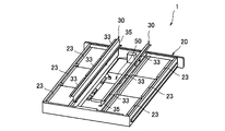
- the housing portion 20 includes a mounting surface 24 on which the battery pack 10 is mounted, four side surfaces 22 and 22A, and a first fixing component installed on a pair of mutually opposing side surfaces 22 among the side surfaces 22 and 22A. 23 and The housing portion 20 is configured so that the mounting surface 24 and the four side surfaces 22 and 22A substantially surround a substantially rectangular parallelepiped housing space 45 .
- the bracket 30 includes a side wall surface 35 provided inside the accommodation space 45 so as to face the side surface 22 on which the first fixing component 23 is installed, and a second fixing component 33 installed on the side wall surface 35. include.
- FIG. 3 is a perspective view of a storage case 1A further provided with a cover plate 40 that covers the storage space 45 of the storage case 1 in addition to the storage case 1 that stores the battery pack 10 .
- Cover plate 40 is fixed to bracket 30 .
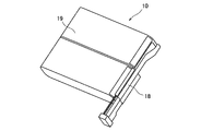
- FIG. 10 A perspective view of the battery pack 10 is shown in FIG.
- the battery pack 10 is entirely covered and fixed with a heat-shrinkable tube 19 .
- a heat-shrinkable tube for example, HISHITUBE (registered trademark) can be used.
- HISHITUBE registered trademark
- Each electrode drawn out from the battery pack 10 is put together in a harness 18 , and the electrical connection between the battery pack 10 and an external circuit is established via the harness 18 .
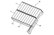
- Battery pack 10 is configured by integrating a plurality of secondary batteries. For example, 20 cylindrical batteries 11 are connected in series via lead plates 12, and lead electrodes 13 are added (FIG. 5A).
- the lead plates 12 may be fixed to the positive and negative electrodes of each battery by, for example, resistance welding.
- FIG. 5B shows an exploded perspective view of a laminate in which 20 assembled batteries are stacked in two stages.
- the lead electrodes 13 drawn out from each assembled battery are connected to the harness 18, and the harness 18 is attached to the laminated body of the assembled battery. Then, with the harness 18 exposed, this laminate is placed in a heat-shrinkable tube 19, and the tube is heat-shrunk to form the battery pack 10 shown in FIG.
- the length direction of the batteries is the first direction A
- the parallel direction of the batteries is the second direction B
- the first direction and the second direction With the direction perpendicular to both directions as the third direction C, the orientation of the battery pack 10 when it is housed in the housing case is shown in FIG.
- the second direction of the battery pack 10 faces the Y direction in FIG. 1
- the third direction of the battery pack 10 faces the Z direction in FIG.
- Both sides of the battery pack 10 in the first direction A are held by the side surface 22 and the side wall surface 35 facing the side surface 22, and both sides in the third direction C are held by the mounting surface 24 and the first fixing It is held by both the part 23 and the second fixing part 33, and both sides in the second direction B are supported by bent portions (described later) provided at both ends of the first fixing part 23 and the second fixing part. be.
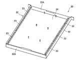
- FIG. 6 is a perspective view of the housing portion 20 of the housing case 1 of one embodiment.
- the housing portion 20 includes a mounting surface 24 on which the battery pack 10 is mounted, a side surface 22 , and a first fixing component 23 installed on the side surface 22 .
- the housing portion 20 is configured to surround a rectangular parallelepiped housing space 45 with a mounting surface 24 formed of a rectangle and four side surfaces 22 and 22A that rise substantially perpendicularly from the respective sides of the mounting surface 24 .
- an opening for placing an object such as the battery pack 10 to the housing portion 20 is arranged on the surface facing the mounting surface 24 having a rectangular parallelepiped shape.
- the receptacle 20 comprises two sides 22 facing each other, with three first fixing parts 23 arranged on each side 22 . These first fixing parts 23 are preferably integrated with the side surface 22 of the housing portion 20 .
- the first fixing part 23 has a rib-like shape rising from the side surface 22 in a substantially vertical direction. This rib-like portion constitutes a flat portion 23 a extending substantially parallel to the mounting surface 24 .
- a connecting portion 23c is arranged between the flat portion 23a and the side surface 22 .
- the flat portion 23a is supported on the side surface 22 by a connecting portion 23c.
- the length direction 23X of the rib-shaped flat portion 23a faces parallel to the side surface 22 on which the first fixing component 23 is installed.
- connection part 23c is not arranged in the vicinity of both ends of the flat part 23a, and two bending parts 23b extending from the vicinity of both ends are arranged.
- the two bent portions 23b are bent in the direction from the flat portion 23a toward the mounting surface 24. As shown in FIG.
- the two bent portions 23b are configured to be symmetrical with respect to the flat portion 23a.
- the side surface 22 of the housing portion 20 and the first fixed component, that is, the connecting portion 23c, the flat portion 23a, and the two bent portions 23b are preferably integrated. These extend continuously from the side surface 22 via the connecting portion 23c and the flat portion 23a to the two bent portions 23b, and can be entirely made of the same material.
- the flat portion 23a has a flat surface 23a1 of length L1, and the connecting portion 23c extends from each bent portion 23b with a margin of L2, that is, the length of (L1 ⁇ 2 ⁇ L2) extends between the side surface 22 and the flat portion. 23a.
- the bent portion 23b has two bent surfaces 23b1 each having a length L3. Each of the two curved surfaces 23b1 forms an angle ⁇ with respect to the flat surface 23a1 and extends from the flat surface 23a1 toward the mounting surface 24.
- the two curved surfaces 33b1 are symmetrical to each other with the flat surface 33a1 interposed therebetween, and form a V-shape.
- the angle ⁇ is preferably about 45 degrees where the curved surface 23b1 is tangent to the arc. .
- the angle ⁇ is preferably 90 degrees.
- the angle ⁇ can be adjusted within a range from 45 degrees to 90 degrees according to the shape of the battery pack 10 .
- FIG. 9 is an enlarged view of the first fixing component 23, and the cushion material 26 is arranged on the surface of the first fixing component 23 facing the mounting surface 24.
- FIG. The cushion material 26 is arranged on the entire connection portion 23c of the first fixing component 23, the flat surface 23a1 of the flat portion 23a, and the curved surface 23b1 of the curved portion 23b.
- the cushion material 26 functions as an elastic body by being sandwiched between the battery pack 10 and the first fixing component 23 when the battery pack 10 is placed in the housing portion 20 .
- the cushioning material 26 can be attached to the surface of the first fixing component 23 with an adhesive such as double-sided tape.
- a film 27 can be added to the surface of the cushion material 26 (Fig. 10). When the film 27 is added, this film 27 contacts the battery pack 10 .
- a material whose surface has good sliding properties For example, a thin film material containing polyethylene terephthalate (PET) as a main component can be used. Mylar (registered trademark) sheets are particularly preferred.
- FIG. 11 shows a perspective view of the battery pack 10 housed in the housing portion 20 of the housing case 1, including a cut surface in the vicinity of the first fixing component 23.
- the surface of the battery pack 10 is covered with a heat-shrinkable tube 19, and the surface that contacts the mounting surface 24 and the surface that is held by the first fixing component 23 are generally flat. is.
- the portion of battery pack 10 that abuts on first fixing member 23 has an arcuate outer shape reflecting the cylindrical shape of each battery constituting battery pack 10 (see FIG. 4).
- the battery pack 10 is held on both sides in the third direction C by the mounting surfaces 24 facing each other and the flat surface 23a1 of the flat portion 23a of the first fixing component 23 .
- Two arcuate portions of the outer shape of battery pack 10 that are opposite to each other are supported from both sides by bent surfaces 23b1 of two bent portions 23b of first fixing component 23 .
- a cushion material 26 and a film 27 are arranged on the flat surface 23a1 and the curved surface 23b1 of the first fixing component 23, and the film 27 and the heat-shrinkable tube 19 of the battery pack 10 are in contact with each other.
- the cushioning material 26 is a force applied from the battery pack 10 to the mounting surface 24 and the flat surface 23a1 of the flat portion 23a of the first fixing component 23, and the vibration of the battery pack 10 caused by the vibration of the housing case 1 as a whole. function as an elastic body against the vibration of This greatly contributes to preventing movement of the battery pack 10 within the housing portion 20 .
- the cushion material 26 functions as an elastic body against the force applied from the battery pack 10 between the bent surfaces 23b1 of the two bent portions 23b and against the vibration of the battery pack 10. It contributes greatly to the deterrence of moving inside.
- FIG. 12 shows a perspective view of part of the bracket 30 of the storage case 1 of one embodiment.
- the bracket 30 includes a side wall surface 35 (shown in FIGS. 1 and 2), a second fixing component 33 and a fixing portion 32 for mounting the second fixing component 33 to the side wall surface 35 .
- three second fixing parts 33 are arranged on the fixing part 32 .
- FIG. 13 is an enlarged view of the second fixing component 33 of the bracket 30.
- the second fixing part 33 has a rib-like shape rising from the fixing part 32 .
- This rib-like portion constitutes a flat surface 33a1 of the flat portion 33a that extends substantially parallel to the mounting surface 24.
- a connecting portion 33c is arranged between the flat surface 33a1 and the fixed portion 32.
- the flat portion 33a is supported by the fixed portion 32 through the connecting portion 33c.
- the length direction 33X of the rib-shaped flat portion 33a faces parallel to the side wall surface 35 on which the second fixing component 33 is installed.
- connection part 33c is not arranged near both ends of the flat part 33a, and two bent parts 33b extending from the vicinity of both ends are arranged.
- the two bent portions 33b are bent in a direction from the flat portion 33a toward the mounting surface 24. As shown in FIG.
- the two bent portions 33b are configured to be symmetrical with respect to the flat portion 33a.
- the fixed part 32 and the second fixed part 33 that is, the connection part 33c, the flat part 33a and the bent part 33b are preferably integrated. These extend continuously from the fixed portion 32 to the bent portion 33b via the connecting portion 33c and the flat portion 33a, and can be entirely made of the same material.
- the second fixing part 33 preferably has the same shape as the first fixing part 23 whose front view is shown in FIG.
- the flat portion 33a has a flat surface 33a1 of length L1, and the connection portion 33c extends from each bent portion 33b with a margin of L2, that is, the length of (L1 ⁇ 2 ⁇ L2) between the side surface 22 and the flat portion. 33a.
- the bent portion 33b has two bent surfaces 33b1 each having a length L3. Each of the two curved surfaces 33b1 forms an angle ⁇ with respect to the flat surface 33a1 and extends from the flat surface 33a1 toward the mounting surface 24.
- the two curved surfaces 33b1 are symmetrical to each other with the flat surface 33a1 interposed therebetween and form a V-shape.
- the angle ⁇ is preferably about 45 degrees where the curved surface 23b1 is tangent to the arc.
- the angle ⁇ is preferably 90 degrees.
- the angle ⁇ can be adjusted within a range from 45 degrees to 90 degrees according to the shape of the battery pack 10 .
- FIG. 15 is a perspective view of the bracket 30 as seen from the mounting surface 24 side.
- the bracket 30 further includes a fence-like side wall surface 35 that is connected to the fixing portion 32 and rises in a direction substantially orthogonal to the flat portion 33 a of the second fixing component 33 .
- the side wall surface 35 extends from one end of the fixed portion 32 to the other end and has approximately the same length as the fixed portion 32 .
- the side wall surface 35 extends substantially parallel to the side surface 22 of the housing portion 20 .
- Both sides of the battery pack 10 in the third direction C are also held by the mounting surface 24 and the flat surface 33 a 1 of the second fixing component 33 .
- Two arcuate portions of the outer shape of battery pack 10 are supported by two curved surfaces 33b1 of second fixing component 33 from both sides.
- Cushion material 36 is arranged on flat surface 33 a 1 and curved surface 33 b 1 of second fixing component 33 and is in contact with heat-shrinkable tube 19 of battery pack 10 .
- the cushion material 36 functions as an elastic body against the force applied from the battery pack 10 between the mounting surface 24 and the flat surface 33a1 and the vibration of the battery pack 10 caused by the vibration of the housing case 1 as a whole. This greatly contributes to restraining the movement of the battery pack 10 within the housing portion 20 .
- the cushion material 36 functions as an elastic body against the force applied from the battery pack 10 between the two curved surfaces 33b1 and the vibration of the battery pack 10, and the movement of the battery pack 10 within the housing portion 20. contribute significantly to the prevention of
- the cushion material 36 is also arranged on the surface of the side wall surface 35 of the bracket 30 .
- Battery pack 10 is held by side wall surface 35 of bracket 30 and side surface 22 of housing portion 20 facing each other.
- the cushion material 36 functions as an elastic body against the force applied from the battery pack 10 between the side surface 22 of the housing portion 20 and the side wall surface 35 of the bracket 30 and against the vibration of the battery pack 10 . It greatly contributes to deterring movement within 20.
- FIG. A state in which three battery packs 10 are placed is shown.
- Bracket 30 holds battery pack 10 with flat surface 3 a 1 of flat portion 33 a of second fixing component 33 and mounting surface 24 of housing portion 20 , and holds battery pack 10 with side wall surface 35 of housing portion 20 and side surface 22 of housing portion 20 .
- the battery pack 10 is supported by the curved surfaces 33b1 of the two curved portions 33b of the second fixing component 33, and is fixed to the mounting surface 24 of the housing portion 20 by the fixing means 52.
- a screw for example, can be used as the fixing means 52 .
- fastening means 52 such as rivets may be used.
- the housing portion 20 includes a mounting surface 24 on which the battery pack 10 is mounted, four side surfaces 22 and 22A, and a first fixed portion installed on a pair of mutually opposing side surfaces 22 among the side surfaces 22 and 22A. a part 23;
- the housing portion 20 is configured so that the mounting surface 24 and the four side surfaces 22 and 22A substantially surround a substantially rectangular parallelepiped housing space 45 .
- One surface of the accommodation space 45 serves as an opening of the accommodation portion 20 for placing an object to be mounted on the accommodation portion 20 such as the battery pack 10 . (See Figure 6).
- the first fixing part 23 is installed on the side surface 22 of the housing part 20 and has a rib-like shape. This rib-like portion constitutes a flat portion 23 a extending substantially parallel to the mounting surface 24 .
- the first fixing component 23 is provided with two bent portions 23b extending from the vicinity of both ends of the flat portion 23a. The two bent portions 23b are bent in the direction from the flat portion 23a toward the mounting surface 24 (see FIG. 7).
- a cushion material 26 is attached to the surface of the first fixing component 23 facing the mounting surface 24 .
- the cushion material 26 is attached to the entire connecting portion 23c, the flat portion 23a, and the two bent portions 23b of the first fixing component 23.
- a film 27 is attached to the cushion material 26 to improve the sliding property of the surface thereof (see FIGS. 9 and 10).
- the bracket 30 that constitutes the storage case 1 is prepared.
- the bracket 30 includes a fixing portion 32 , a second fixing component 33 , and a fence-like side wall surface 35 connected to the fixing portion 32 .
- the second fixing part 33 has a rib-like shape substantially perpendicular to the side wall surface 35 .
- This rib-like portion constitutes a flat portion 33 a of the second fixing component 33 extending substantially parallel to the mounting surface 24 .
- the second fixing component 33 has two bent portions 33b extending from near both ends of the flat portion 33a. The two bent portions 33b are bent in the direction from the flat portion 33a toward the mounting surface 24 (see FIG. 12).
- a cushion material 36 is attached to the surface of the second fixing component 33 facing the mounting surface 24 .
- the cushion material 36 is attached to the entire connecting portion 23c, flat portion 23a, and two bent portions 33b of the first fixing component 23. As shown in FIG. Furthermore, a cushion material 36 is attached to the surface of the side wall surface 35 as well. (See FIG. 15).
- the battery pack 10 is inserted into the housing portion 20 through the opening of the housing portion 20, and the bottom surface 10a of the battery pack 10 is placed. is brought into contact with the mounting surface 24 .
- surface 10b of battery pack 10 is moved. It is brought into contact with the film 27 (see FIG. 11) attached to the surface of the first fixing component 23 .
- the surface 10b of the battery pack 10 is rotated around the contact portion 10c where the surface 10b of the battery pack 10 is in contact with the film 27, while the battery pack 10 is rotated in the direction of the arrow a.
- the battery pack 10 is inserted between the first fixing component 23 and the mounting surface 24 .
- the battery pack 10 is in contact with the film 27 having good sliding properties, and the battery pack 10 is inserted while sliding on the surface thereof. Therefore, the battery pack 10 can be smoothly inserted into the cushion material 26 between the film 27 and the first fixing component 23 without causing unnecessary deformation due to stress in the insertion direction.
- the bracket 30 is temporarily placed on the battery pack 10 .
- the curved surfaces 33b1 of the two curved portions 33b of the second fixing member 33 and the arcuate portions at both ends of the battery pack 10 are in contact with each other, and the flat surface 33a1 of the flat portion 33a of the second fixing member 33 is in contact with the battery pack.
- 10 and the side wall surface 35 of the bracket 30 is temporarily placed in contact with the side surface 10d of the battery pack 10 .
- the side wall surface 35 of the bracket 30 presses the side surface 10 d of the battery pack 10 toward the side surface 22 of the housing portion 20 to bring the battery pack 10 into contact with the side surface 22 of the housing portion 20 . Furthermore, by pressing bracket 30 toward mounting surface 24 , flat surface 33 a 1 of flat portion 33 a of second fixing component 33 and bent surfaces 33 b 1 of two bent portions 33 b of second fixing component 33 support battery pack 10 . is pressed against the mounting surface 24 . In this manner, the bracket 30 is fixed to the mounting surface 24 using the fixing means 52 while the battery pack 10 is in contact with the side surface 22 of the housing portion 20 and pressed against the mounting surface 24 . As the fixing means 52, screws can be screwed together.
- a method for housing the battery pack 10 in the housing case 1 has been described above, and a battery unit including the battery pack 10 and the housing case 1 housing the battery pack 10 can be manufactured by the method described here. . Therefore, it can be used as a method for manufacturing a battery unit having such a configuration. .
Landscapes
- Chemical & Material Sciences (AREA)
- Chemical Kinetics & Catalysis (AREA)
- Electrochemistry (AREA)
- General Chemical & Material Sciences (AREA)
- Battery Mounting, Suspending (AREA)
Abstract
電池パック10を収容する収容ケース1は、収容部20とブラケット30とを備え、収容部は電池パックを載置する載置面24と第1固定部品23が設置された側面22とを含み、ブラケットは収容部の側面と対向する側壁面35とその側壁面に設置された第2固定部品33とを含み、第1固定部品および第2固定部品のそれぞれは平坦面23a1、33a1および平坦面から載置面に向かって延在する2つの屈曲面23b1、33b1を有し、電池パックは、収容部の載置面と第1固定部品および第2固定部品のそれぞれの平坦面の両方とで保持され、収容部の側面とブラケットの側壁面とで保持され、第1固定部品の2つの屈曲面で支持されると共に、第2固定部品の2つの屈曲面で支持される。
Description
本発明は、収容ケースおよびその収容ケースに電池パックを収容する方法に関し、特に、複数の二次電池を組み合わせて構成された電池パックを収容する収容ケースおよびその収容ケースに少なくとも1つの電池パックを収容する方法に関する。
停電時の電源をバックアップする無停電電源装置や非常用の電源装置、あるいは再生エネルギーによる発電システムの蓄電装置などの様々な用途に、充電可能な二次電池を多数組み合わせて構成された電池ユニットが使用されている。このような電池ユニットは、通常、箱形の収容ケースに少なくとも1つの電池パックが収容されている。
電池ユニットを運搬するとき、また所定の場所に設置して稼働するときに、電池ユニットに外部から衝撃や振動が加わることは不可避であり、このような衝撃や振動により電池パックが電池ユニットの中で移動する場合がある。電池パックの移動は、電池パックを接続するソケットが外れる、接続配線が断線する、電池パック自体が破損する、などの不具合を生じさせる虞があり、電池パックは電池ユニットの収容ケースの中でしっかりと固定する必要がある。
電池パックを収容ケースに固定する方法としては、例えば、特許文献1に記載されているように、L字形の固定部品を収容ケースの電池を載置する載置面に配設して仕切壁を構成し、その仕切壁で、収容ケース内での電池パックの載置位置を画定して収容ケースに固定する構造が知られている。
このような技術においては、L字形の固定部品を別途作成する必要があるため部品点数が増加する。また、部品点数が増加するとそれらを取り付ける製造工程を追加することになる。加えて、別途作成した固定部品を追加工程にて取り付けるため、取り付け時に一定程度の位置合わせ余裕を設定しなければならない。これらは、電池パック載置位置の位置精度の低下、および製造コスト増大の要因となる。
本開示はこのような課題を鑑みてなされたものであり、その目的とするところは、固定部品を収容ケースと一体化することにより電池パックの載置位置精度が向上し、部品点数および製造工程数が削減されることでより低廉な製造コストで製造可能である、電池パックを収容する収容ケースおよびその電池パックを収容ケースに収容する方法、、を提供することにある。
本開示の一つの態様による収容ケースは、複数の電池を組み合わせて構成された電池パックを収容する収容ケースであって、収容部と、ブラケットと、を備え、収容部は、電池パックを載置する載置面と、その載置面から立ち上がる少なくとも1つの側面と、側面に設置された第1固定部品と、を含み、第1固定部品は、平坦面と2つの屈曲面とを有し、平坦面は側面に対して概ね垂直であり、かつ載置面に対して略平行に延在し、2つの屈曲面の各々は平坦面から載置面に向かって延在してハの字形状で互いに向き合っており、ブラケットは、収容部の載置面に固定されており、ブラケットは収容部の側面に対して略平行に延在する側壁面と、その側壁面に設置された第2固定部品と、を含み、第2固定部品は、平坦面と2つの屈曲面を有し、平坦面は側壁面に対して概ね垂直であり、かつ載置面に対して略平行に延在し、2つの屈曲面の各々は平坦面から載置面に向かって延在してハの字形状で互いに向き合っており、電池パックは、収容部の載置面と、第1固定部品の平坦面および第2固定部品の平坦面の両方と、で保持され、収容部の側面とブラケットの側壁面とで保持され、第1固定部品の2つの屈曲面で支持されると共に、第2固定部品の2つの屈曲面で支持される、ことを特徴とする。
本開示の一つの態様による電池パックを、本開示の一つの態様による収容ケースに収容する方法であって、電池パックは、収容ケースに収容されたときに載置面と接する底面と、底面と互いに対向する上面とを備え、電池パックの底面が載置面に対して斜めの状態で、電池パックの一方の側の上面の一端を第1固定部品の平坦面に当接させるステップと、第1固定部品の平坦面に当接させた部分を支点として、電池パックの底面が載置面に対して概ね平行になるまで、電池パックを回動させて、電池パックの一方の側を載置面と第1固定部品との間に挿入するステップと、ブラケットの側壁面で電池パックの一方の側と反対側の他方の側を収容部の側面に向かって押圧して、電池パックの一方の側を収容部の側面に当接させるステップと、ブラケットにより電池パックを収容部の載置面に向かって押圧することで、第2固定部品の平坦面および第2固定部品の屈曲面により電池パックを載置面に押し付けて、ブラケットを載置面に固定手段を用いて固定するステップと、を備える、ことを特徴とする方法である。
本開示の収容ケースその収容ケースに電池パックを収容する製造方法は、固定部品を収容ケースと一体化することにより電池パックの載置位置精度が向上し、部品点数および製造工程数が削減されることでより低廉な製造コストで製造可能である、電池パックを収容する収容ケースおよびその電池パックを収容ケースに収容する方法、を提供する。
以下、図面に基づき本発明の一実施形態について説明する。
<一実施形態>
図1に、一実施形態の電池パック10を収容した収容ケース1を備える電池ユニットの斜視図を示す。収容ケース1は、収容部20とブラケット30と制御回路50とを備える。ブラケット30は収容部20に固定されている。図2には、図1の状態からからブラケット30を外した状態の収容ケース1の分解斜視図を示す。
図1に、一実施形態の電池パック10を収容した収容ケース1を備える電池ユニットの斜視図を示す。収容ケース1は、収容部20とブラケット30と制御回路50とを備える。ブラケット30は収容部20に固定されている。図2には、図1の状態からからブラケット30を外した状態の収容ケース1の分解斜視図を示す。
収容部20は、電池パック10を載置する載置面24と、4つの側面22、22Aと、これらの側面22、22Aのうち1対の互いに対向する側面22に設置された第1固定部品23と、を含む。この収容部20は実質的に載置面24と4つの側面22、22Aとはとは、実質的に直方体形状の収容空間45を囲むように構成される。ブラケット30は、第1固定部品23が設置されている側面22と対向するように収容空間45の内に設けられた側壁面35と、側壁面35に設置された第2固定部品33と、を含む。
図3は、電池パック10を収容した収容ケース1に加えて、収容ケース1の収容空間45を覆う蓋板40をさらに備えた収容ケース1Aの斜視図である。蓋板40はブラケット30に固定されている。
図4に、電池パック10の斜視図を示す。電池パック10はその全体を熱収縮チューブ19で覆い固定している。熱収縮チューブとして、例えば、ヒシチューブ(登録商標)を用いることができる。電池パック10から引き出された各電極はハーネス18にまとめられており、電池パック10と外部回路との電気的な接続はハーネス18を介して行われる。
図5Aから図5Cに、電池パック10の内部構造を示す。電池パック10は複数の二次電池を集積して構成される。例えば、20本の円筒形の電池11がリード板12を介して直列接続され、電極を引き出すリード電極13が付加されている(図5A)。リード板12は、各々の電池の正極および負極に、例えば、抵抗溶接により固定し得る。
さらに、20本の電池11をまとめた組電池の電極の各々およびリード板12の各々を外部から絶縁するために、それらの表面は絶縁シート16で覆われている。その組電池のリード板12が配置された面とは反対側の面の電極の各々およびリード板14についても同様に絶縁シート16で覆われている。これらの絶縁シート16は、例えば、両面テープにより貼付することで固定し得る。さらに、この組電池を複数個積層する場合には、それぞれの絶縁シート16の間にさらに絶縁板17を配置することが好ましい。例えば、20本をまとめた組電池を2段積層する積層体の分解斜視図を図5Bに示す。
各組電池から引き出されてるリード電極13をハーネス18に接続し、ハーネス18を組電池の積層体に取り付ける。そして、ハーネス18部分が露出させて状態でこの積層体を熱収縮チューブ19内に入れ、チューブを熱収縮させて図1に記載の電池パック10を構成する。
ここで、上記のような電池パック10において、図5Aに示すように、前記電池の長さ方向を第1方向A、前記電池の並列方向を第2方向B、そして、第1方向と第2方向の両方に直行する方向を第3方向Cとして、電池パック10が、収容ケースに収容される際の向きを、図1を参照して示すと、電池パック10の第1方向が、図1におけるX方向に、電池パック10の第2方向が、図1におけるY方向に、そして、電池パック10の第3方向が、、図1におけるZ方向に向くように配置される。
そして、電池パック10の第1方向Aの両側は、側面22とこの側面22と対向する側壁面35とで保持され、前記第3方向Cの両側が、前記載置面24と、第1固定部品23および第2固定部品33の両方と、で保持され、第2方向Bの両側が、第1固定部品23、第2固定部品のそれぞれの両端に設けられた屈曲部(後述)で支持される。
図6は、一実施形態の収容ケース1の収容部20の斜視図である。収容部20は、電池パック10を載置する載置面24と、側面22と、その側面22に設置された第1固定部品23と、を含む。収容部20は、長方形からなる載置面24と載置面24のそれぞれの辺から概ね垂直に立ち上がる4つの側面22、22Aとで直方体形状の収容空間45を囲むように構成される。ただし、直方体形状の載置面24に対向する面には、電池パック10等の収容部20への搭載物を載置するための開口が配置されている。図6の一実施形態では、収容部20は互いに対向する2つの側面22を含み、それぞれの側面22に3つずつの第1固定部品23が配置されている。これら第1固定部品23は、収容部20の側面22と一体化していることが好ましい。
図7に第1固定部品23の拡大図を示す。第1固定部品23は、側面22から概ね垂直な方向に立ち上がるリブ状の形状を有する。このリブ状の部分は、載置面24に対して略平行に延在する平坦部23aを構成する。平坦部23aと側面22との間には接続部23cが配置されている。平坦部23aは接続部23cにより側面22に支持されている。リブ状の平坦部23aの長さ方向23Xは、当該第1固定部品23が設置される側面22と平行に向いている。
平坦部23aの両端近傍には接続部23cが配置されておらず、それら両端近傍のそれぞれから延伸する2つの屈曲部23bが配置されている。2つの屈曲部23bは、平坦部23aから載置面24へ向かう方向に屈曲している。2つの屈曲部23bは、平坦部23aに対して互いに対称となるように構成される。
収容部20の側面22と第1固定部品、すなわち、接続部23c、平坦部23a、および2つの屈曲部23bは、一体化されていることが好ましい。これらは、側面22から、接続部23c、平坦部23aを経由して2つの屈曲部23bまで連続して延在し、その全体が同一材料で構成され得る。
図8に、第1固定部品23の正面図を示す。平坦部23aは長さL1の平坦面23a1を有し、接続部23cは、それぞれの屈曲部23bから延伸部L2の余裕をもって、すなわち(L1-2×L2)の長さで側面22と平坦部23aとを接続する。屈曲部23bはそれぞれ長さL3の2つの屈曲面23b1を有する。2つの屈曲面23b1の各々は平坦面23a1に対して角度θをなし、平坦面23a1から載置面24に向かって延在する。2つの屈曲面33b1は平坦面33a1を挟んで互いに対称であり、ハの字形状を構成する。例えば、電池パック10の外形に個々の円筒形の電池11の形状が反映されて円弧状の形状を有するとき、この角度θは屈曲面23b1が円弧の接線となる概ね45度とすることが好ましい。また、電池パック10の外形が直方体形状であるときは、角度θは90度とすることが好ましい。このように、角度θは45度から90度までの範囲で電池パック10の形状に応じて調整し得る。
図9は、第1固定部品23の拡大図であり、第1固定部品23の載置面24と対向する面にクッション材26が配置されている。クッション材26は、第1固定部品23の接続部23c、平坦部23aの平坦面23a1、および屈曲部23bの屈曲面23b1の全体に配置されている。このクッション材26は、電池パック10が収容部20に載置された状態で、電池パック10と第1固定部品23の間に挟まれて弾性体として機能する。クッション材26は、接着剤、例えば、両面テープにより第1固定部品23の表面に貼付され得る。
このクッション材26の表面に、さらにフィルム27を付加することができる(図10)。フィルム27が付加されたときは、このフィルム27が電池パック10に当接する。フィルム27としては、その表面の滑り特性が良好な材料を用いることが好ましく、例えば、ポリエチレンテレフタレート(PET)を主成分する薄膜材料が使用され得る。特に、マイラー(登録商標)シートが好適である。
図11に、収容ケース1の収容部20に収容された電池パック10の、第1固定部品23の近傍における切断面を含む斜視図を示す。図中では省略しているが、電池パック10は、その表面が熱収縮チューブ19で覆われており、載置面24と当接する面および第1固定部品23に保持される面は、概ね平坦である。また、電池パック10が第1固定部品23に当接する部分は、電池パック10を構成する個々の電池の円筒形の形状を反映して円弧状の外形を有する(図4参照)。
電池パック10は、その第3方向Cの両側が、互いに対向する載置面24と第1固定部品23の平坦部23aの平坦面23a1とで保持される。電池パック10の外形において互いに反対側にある2つの円弧状の部分は、第1固定部品23の2つの屈曲部23bの屈曲面23b1で両側から支持される。第1固定部品23の平坦面23a1および屈曲面23b1には、クッション材26及びフィルム27が配置され、フィルム27と電池パック10の熱収縮チューブ19とが当接する。
また、クッション材26は、載置面24や第1固定部品23の平坦部23aの平坦面23a1に対して電池パック10から加わる力や、収容ケース1全体の振動に起因して生じる電池パック10の振動に対して弾性体として機能する。これは、電池パック10が収容部20の中で移動することの抑止に大きく貢献する。同様に、クッション材26は、2つの屈曲部23bの屈曲面23b1の間に電池パック10から加わる力や、電池パック10の振動に対しても弾性体として機能し、電池パック10が収容部20の中で移動することの抑止に大きく貢献する。
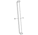
図12に、一実施形態の収容ケース1のブラケット30の一部の斜視図を示す。ブラケット30は、側壁面35(図1,図2に示す)と、第2固定部品33と、第2固定部品33を側壁面35に設置するための固定部32とを含む。図12の実施形態では、固定部32には、3つの第2固定部品33が配置されている。
図13は、ブラケット30の第2固定部品33の拡大図である。第2固定部品33は、固定部32から立ち上がるリブ状の形状を有する。このリブ状の部分は、載置面24に対して略平行に延在する平坦部33aの平坦面33a1を構成する。平坦面33a1と固定部32との間には接続部33cが配置されている。平坦部33aは接続部33cにより固定部32に支持されている。リブ状の平坦部33aの長さ方向33Xは、当該第2固定部品33が設置される側壁面35と平行に向いている。
平坦部33aの両端近傍には接続部33cが配置されておらず、それら両端近傍のそれぞれから延伸する2つの屈曲部33bが配置されている。2つの屈曲部33bは、平坦部33aから載置面24へ向かう方向に屈曲している。2つの屈曲部33bは、平坦部33aに対して対称形となるように構成される。
固定部32と第2固定部品33、すなわち、接続部33c、平坦部33a、および屈曲部33bは、一体化されていることが好ましい。これらは、固定部32から、接続部33c、平坦部33aを経由して、屈曲部33bまで連続して延在し、その全体が同一材料で構成され得る。
図14に第2固定部品33の正面図を示す。第2固定部品33は、図8に正面図が示された第1固定部品23と同一の形状を有することが好ましい。平坦部33aは長さL1の平坦面33a1を有し、接続部33cは、それぞれの屈曲部33bから延伸部L2の余裕をもって、すなわち(L1-2×L2)の長さで側面22と平坦部33aとを接続する。屈曲部33bはそれぞれ長さL3の2つの屈曲面33b1を有する。2つの屈曲面33b1の各々は平坦面33a1に対して角度θをなし、平坦面33a1から載置面24に向かって延在する。2つの屈曲面33b1は平坦面33a1を挟んで互いに対称でありハの字形状を構成する。例えば、電池パック10の外形に個々の円筒形の電池11の形状が反映されて円弧状の形状を有するとき、この角度θは屈曲面23b1が円弧の接線となる概ね45度とすることが好ましい。また、電池パック10の外形が直方体形状であるときは、角度θは90度とすることが好ましい。このように、角度θは45度から90度までの範囲で電池パック10の形状に応じて調整し得る。
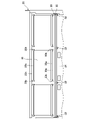
図15は、ブラケット30を載置面24側からみた斜視図である。ブラケット30は、固定部32に接続されて、第2固定部品33の平坦部33aに対して概ね直交する方向に立ち上がる塀状の側壁面35をさらに含む。この側壁面35は、固定部32の一端から他端まで延在し、概ね固定部32と同じ長さを有する。側壁面35は、収容部20の側面22に対し略平行に延在する。
電池パック10は、その第3方向Cの両側が、載置面24と第2固定部品33の平坦面33a1とによっても保持される。電池パック10の外形の2つの円弧状の部分(図11において符号11a、11bで示す部分)は、第2固定部品33の2つの屈曲面33b1で両側から支持される。第2固定部品33の平坦面33a1および屈曲面33b1には、クッション材36が配置され電池パック10の熱収縮チューブ19と当接している。
また、クッション材36は、載置面24と平坦面33a1との間に電池パック10から加わる力や、収容ケース1全体の振動に起因する電池パック10の振動に対して弾性体として機能し、電池パック10の収容部20の中での移動の抑止に大きく貢献する。同様に、クッション材36は、2つの屈曲面33b1の間に電池パック10から加わる力や、電池パック10の振動に対して弾性体として機能し、電池パック10の収容部20の中での移動を抑止することに大きく貢献する。
クッション材36は、さらにブラケット30の側壁面35の表面にも配置されている。電池パック10は、互いに対向するブラケット30の側壁面35と収容部20の側面22とで保持される。クッション材36は、収容部20の側面22とブラケット30の側壁面35との間に電池パック10から加わる力や、電池パック10の振動に対して弾性体として機能し、電池パック10の収容部20の中での移動を抑止することに大きく貢献する。
図16に図1の拡大図を示す。電池パック10が3個載置されている状態を示している。ブラケット30は電池パック10を、その第2固定部品33の平坦部33aの平坦面3a1と収容部20の載置面24とで保持し、その側壁面35と収容部20の側面22とで保持し、その第2固定部品33の2つの屈曲部33bの各々の屈曲面33b1で電池パック10を支持した状態で、収容部20の載置面24に固定手段52で固定されている。固定手段52として、例えば、ねじを用いることができる。また、リベットなどの周知の固定手段52も使用し得る。
<一実施形態の方法>
次に、複数の電池11を組み合わせて構成された電池パック10を収容ケース1に収容する方法について説明する。
次に、複数の電池11を組み合わせて構成された電池パック10を収容ケース1に収容する方法について説明する。
まず、収容ケース1を構成する収容部20を準備する。この収容部20は、電池パック10を載置する載置面24と、4つの側面22、22Aと、これらの側面22、22Aのうち1対の互いに対向する側面22に設置された第1固定部品23と、を含む。この収容部20は実質的に載置面24と4つの側面22、22Aとはとは、実質的に直方体形状の収容空間45を囲むように構成される。収容空間45の一面は、収容部20の開口として、電池パック10等の収容部20への搭載物を載置するために供される。(図6参照)。
第1固定部品23は、収容部20の側面22に設置されており、リブ状の形状を有する。このリブ状の部分は、載置面24に対して略平行に延在する平坦部23aを構成する。第1固定部品23には、その平坦部23aの両端近傍のそれぞれから延伸する2つの屈曲部23bが配置されている。2つの屈曲部23bは、平坦部23aから載置面24へ向かう方向に屈曲している(図7参照)。
また、第1固定部品23の、載置面24と対向する側の面にはクッション材26が貼付されている。クッション材26は、第1固定部品23の接続部23c、平坦部23a、および2つの屈曲部23bの全体に貼付されている。このクッション材26には、その表面の滑り特性を良好するフィルム27がさらに貼付されている(図9、図10参照)。
次に、収容ケース1を構成するブラケット30を準備する。ブラケット30は、固定部32と第2固定部品33と固定部32に接続された塀状の側壁面35とを含む。第2固定部品33は、側壁面35に対して概ね直交するリブ状の形状を有する。このリブ状の部分は、載置面24に対して略平行に延在する第2固定部品33の平坦部33aを構成する。第2固定部品33には、その平坦部33aの両端近傍のそれぞれから延伸する2つの屈曲部33bが配置されている。2つの屈曲部33bは、平坦部33aから載置面24へ向かう方向に屈曲している(図12参照)。
また、第2固定部品33の、載置面24と対向する側の面にはクッション材36が貼付されている。クッション材36は、第1固定部品23の接続部23c、平坦部23a、および2つの屈曲部33bの全体に貼付されている。さらに、側壁面35の表面にもクッション材36が貼付されている。(図15参照)。
続いて、電池パック10を収容部20の載置面24に載置する手順を、図18を参照して説明する。まず、電池パック10をその第1方向Aが載置面24に対して斜めとなる状態で、電池パック10を収容部20の開口から収容部20の内部に入れて、電池パック10の底面10aの一端を載置面24に接触させる。その状態で、電池パック10の両端の円弧形状部分11a、11bと、第1固定部品23の両端近傍の屈曲部23bのそれぞれと、の位置合わせを大まかに行いながら、電池パック10の表面10bを第1固定部品23の表面に貼付されたフィルム27(図11参照)に当接させる。
次に、電池パック10の側面10dを矢印bの方向へ移動させることで、電池パック10の表面10bがフィルム27に当接した当接部10cを支点として電池パック10を回動させながら矢印aの方向へ押し込むことで、電池パック10を第1固定部品23と載置面24との間に挿入する。このとき、電池パック10は、滑り特性が良好なフィルム27と当接しており、その表面上で電池パック10が滑りながら挿入される。そのため、フィルム27と第1固定部品23との間にあるクッション材26に、挿入方向への応力による無用な変形を生じるさせることなく円滑に電池パック10を挿入することができる。
続いて、ブラケット30を収容部20の載置面24に固定する手順を説明する。まず、ブラケット30を電池パック10上に仮置きする。このとき、第2固定部品33の2つの屈曲部33bの屈曲面33b1および電池パック10の両端の円弧形状部分がそれぞれ接触すると共に、第2固定部品33の平坦部33aの平坦面33a1が電池パック10の表面10bに接触し、さらに、ブラケット30の側壁面35が、電池パック10の側面10d接触するように仮置きする。
この仮置きの状態から、ブラケット30の側壁面35で電池パック10の側面10dを収容部20の側面22に向かって押圧して電池パック10を収容部20の側面22に当接させる。さらに、ブラケット30を載置面24の方向へ押圧することで、第2固定部品33の平坦部33aの平坦面33a1および第2固定部品33の2つの屈曲部33bの屈曲面33b1により電池パック10を載置面24に押し付ける。このように、電池パック10を収容部20の側面22に当接させると共に載置面24に押し付けた状態で、ブラケット30を載置面24に固定手段52を用いて固定する。固定手段52としては、ビスによる螺合とすることができる。
以上説明した収容ケース1に電池パック10を収容する方法について説明したが、ここで説明した方法により、電池パック10と電池パック10を収容する収容ケース1とを備える電池ユニットを製造することができる。よって、このような構成の電池ユニットの製造方法として用いることができる。。
1 収容ケース
10 電池パック
10a 底面
10b 表面
10c 当接部
10d 側面
10 電池パック
11 電池
12 リード板
13 リード電極
14 リード板
16 絶縁シート
17 絶縁板
18 ハーネス
19 熱収縮チューブ
20 収容部
22 側面
23 第1固定部品
23a 平坦部
23a1 平坦面
23b 屈曲部
23b1 屈曲面
23c 接続部
24 載置面
26 クッション材
27 フィルム
30 ブラケット
32 固定部
33 第2固定部品
33a 平坦部
33a1 平坦面
33b 屈曲部
33b1 屈曲面
33c 接続部
35 側壁面
36 クッション材
40 蓋板
42 溶接部
45 収容空間
50 制御回路
52 固定手段
L1 平坦面長さ
L2 延伸部
L3 屈曲面長さ
θ 角度
10 電池パック
10a 底面
10b 表面
10c 当接部
10d 側面
10 電池パック
11 電池
12 リード板
13 リード電極
14 リード板
16 絶縁シート
17 絶縁板
18 ハーネス
19 熱収縮チューブ
20 収容部
22 側面
23 第1固定部品
23a 平坦部
23a1 平坦面
23b 屈曲部
23b1 屈曲面
23c 接続部
24 載置面
26 クッション材
27 フィルム
30 ブラケット
32 固定部
33 第2固定部品
33a 平坦部
33a1 平坦面
33b 屈曲部
33b1 屈曲面
33c 接続部
35 側壁面
36 クッション材
40 蓋板
42 溶接部
45 収容空間
50 制御回路
52 固定手段
L1 平坦面長さ
L2 延伸部
L3 屈曲面長さ
θ 角度
Claims (17)
- 複数の電池を組み合わせて構成された電池パックを収容する収容ケースであって、
収容部と、ブラケットと、を備え、
前記収容部は、前記電池パックを載置する載置面と、前記載置面から立ち上がる少なくとも1つの側面と、前記側面に設置された第1固定部品と、を含み、前記第1固定部品は平坦面と2つの屈曲面とを有し、前記第1固定部品の平坦面は前記側面に対して概ね垂直であり、かつ前記載置面に対して略平行に延在し、前記第1固定部品の2つの屈曲面の各々は前記第1固定部品の平坦面から前記載置面に向かって延在してハの字形状で互いに向き合っており、
前記ブラケットは、前記収容部の前記載置面に固定されており、前記ブラケットは前記収容部の前記側面に対して略平行に延在する側壁面と、前記側壁面に設置された第2固定部品と、を含み、前記第2固定部品は平坦面と2つの屈曲面を有し、前記第2固定部品の平坦面は前記側壁面に対して概ね垂直であり、かつ前記載置面に対して略平行に延在し、前記第2固定部品の2つの屈曲面の各々は前記第2固定部品の平坦面から前記載置面に向かって延在してハの字形状で互いに向き合っており、
前記電池パックは、
前記収容部の前記載置面と、前記第1固定部品の平坦面および前記第2固定部品の平坦面の両方と、で保持され、
前記収容部の前記側面と前記ブラケットの前記側壁面とで保持され、
前記第1固定部品の2つの屈曲面で支持されると共に、前記第2固定部品の2つの屈曲面で支持される、収容ケース。 - 前記第1固定部品は、前記第1固定部品が設置されている前記側面と一体化されている、請求項1に記載の収容ケース。
- 前記第1固定部品の2つの屈曲面の各々は、前記第1固定部品の平坦面に対して45度の角度をなす、請求項1又は2に記載の収容ケース。
- 前記第2固定部品の2つの屈曲面の各々は、前記第2固定部品の平坦面に対して45度の角度をなす、請求項1から3までのいずれか1項に記載の収容ケース。
- 前記収容部は、さらにクッション材を備え、
前記クッション材は、前記第1固定部品の平坦面および前記第1固定部品の屈曲面ならびに前記第2固定部品の平坦面および前記第2固定部品の屈曲面のそれぞれに付加されており、前記第1固定部品の平坦面および前記第1固定部品の屈曲面と前記電池パックとの間に挟まれると共に、前記第2固定部品の平坦面および前記第2固定部品の屈曲面と前記電池パックとの間に挟まれる、請求項1から4までのいずれか1項に記載の収容ケース。 - 前記第1固定部品の平坦面および前記第1固定部品の屈曲面に付加された前記クッション材の表面に、滑り特性が良好なフィルムが付加され、前記フィルムが前記電池パックに当接する、請求項5に記載の収容ケース。
- 前記フィルムは、ポリエチレンテレフタレート(PET)を主成分とする、請求項6に記載の収容ケース。
- 前記ブラケットを前記収容部の前記載置面に固定する固定手段をさらに備える、請求項1から7までのいずれか1項に記載の収容ケース。
- 前記収容ケースは前記収容部を覆う蓋板をさらに備え、前記ブラケットと前記蓋板とは、スポット溶接で一体化されている、請求項1から8までのいずれか1項に記載の収容ケース。
- 前記収容ケースに複数個の前記電池パックが収容され、
前記収容部の前記側面に複数個の前記第1固定部品が配置され、前記ブラケットの前記側壁面に複数個の前記第2固定部品が配置される、請求項1から9までのいずれか1項に記載の収容ケース。 - 前記電池パックを構成する前記複数の電池の各々は円筒形を有する、請求項1から10までのいずれか1項に記載の収容ケース。
- 前記側面と互いに対向する他の側面と、前記他の側面に対応して設けられる他のブラケットと、をさらに備え、前記他の側面にも前記第1固定部品が設置され、前記他のブラケットにも前記第2固定部品が設置される、請求項1から11までのいずれか1項に記載の収容ケース。
- 請求項1に記載の電池パックを、請求項1に記載の収容ケースに収容する方法であって、
前記電池パックは、前記収容ケースに収容されたときに前記載置面と接する底面と、前記底面と互いに対向する上面とを備え、
前記電池パックの前記底面が前記載置面に対して斜めの状態で、前記電池パックの一方の側の前記上面の一端を前記第1固定部品の平坦面に当接させるステップと、
前記第1固定部品の平坦面に当接させた部分を支点として、前記電池パックの前記底面が前記載置面に対して概ね平行になるまで、前記電池パックを回動させて、前記電池パックの前記一方の側を前記載置面と前記第1固定部品との間に挿入するステップと、
前記ブラケットの前記側壁面で前記電池パックの前記一方の側と反対側の他方の側を前記収容部の前記側面に向かって押圧して、前記電池パックの前記一方の側を前記収容部の前記側面に当接させるステップと、
前記ブラケットにより前記電池パックを前記収容部の前記載置面に向かって押圧することで、前記第2固定部品の平坦面および前記第2固定部品の屈曲面により前記電池パックを前記載置面に押し付けて、前記ブラケットを前記載置面に固定手段を用いて固定するステップと、を備える方法。 - 前記収容ケースは、さらにクッション材を備え、
前記クッション材は、前記第1固定部品および前記第2固定部品のそれぞれに付加されており、前記クッション材は、前記第1固定部品と前記電池パックとの間に挟まれると共に、前記第2固定部品と前記電池パックとの間に挟まれるようにして前記電池パックを収容する、請求項13に記載の方法。 - 前記第1固定部品に付加された前記クッション材の表面に、ポリエチレンテレフタレート(PET)を主成分とする滑り特性が良好なフィルムが付加され、前記フィルムが前記電池パックに当接するようにして前記電池パックを収容する、請求項14に記載の方法。
- 前記第1固定部品の平坦面に当接させた部分を支点として、前記電池パックを回動させて、前記電池パックを前記載置面と前記第1固定部品との間に挿入するステップにおいて、
前記電池パックが、前記電池パックに当接する前記フィルムの表面上を滑ることで、前記電池パックを前記載置面と前記第1固定部品との間に挿入することを容易にする、請求項15に記載の方法。 - 前記収容ケースは蓋板をさらに備え、前記蓋板と前記ブラケットとをスポット溶接するステップを含む、請求項13から16までのいずれか1項に記載の方法。
Priority Applications (1)
| Application Number | Priority Date | Filing Date | Title |
|---|---|---|---|
| JP2023508622A JP7501987B2 (ja) | 2021-03-24 | 2021-12-16 | 収容ケースおよびその収容ケースに電池パックを収容する方法 |
Applications Claiming Priority (2)
| Application Number | Priority Date | Filing Date | Title |
|---|---|---|---|
| JP2021-050098 | 2021-03-24 | ||
| JP2021050098 | 2021-03-24 |
Publications (1)
| Publication Number | Publication Date |
|---|---|
| WO2022201672A1 true WO2022201672A1 (ja) | 2022-09-29 |
Family
ID=83396600
Family Applications (1)
| Application Number | Title | Priority Date | Filing Date |
|---|---|---|---|
| PCT/JP2021/046482 Ceased WO2022201672A1 (ja) | 2021-03-24 | 2021-12-16 | 収容ケースおよびその収容ケースに電池パックを収容する方法 |
Country Status (2)
| Country | Link |
|---|---|
| JP (1) | JP7501987B2 (ja) |
| WO (1) | WO2022201672A1 (ja) |
Citations (4)
| Publication number | Priority date | Publication date | Assignee | Title |
|---|---|---|---|---|
| JPS5398315U (ja) * | 1977-01-13 | 1978-08-09 | ||
| JP2001097049A (ja) * | 1999-10-01 | 2001-04-10 | Fuji Heavy Ind Ltd | 電気自動車用バッテリボックス構造 |
| JP2006140025A (ja) * | 2004-11-12 | 2006-06-01 | Gs Yuasa Corporation:Kk | 組電池 |
| WO2017073416A1 (ja) * | 2015-10-30 | 2017-05-04 | 日立オートモティブシステムズ株式会社 | 蓄電装置 |
-
2021
- 2021-12-16 JP JP2023508622A patent/JP7501987B2/ja active Active
- 2021-12-16 WO PCT/JP2021/046482 patent/WO2022201672A1/ja not_active Ceased
Patent Citations (4)
| Publication number | Priority date | Publication date | Assignee | Title |
|---|---|---|---|---|
| JPS5398315U (ja) * | 1977-01-13 | 1978-08-09 | ||
| JP2001097049A (ja) * | 1999-10-01 | 2001-04-10 | Fuji Heavy Ind Ltd | 電気自動車用バッテリボックス構造 |
| JP2006140025A (ja) * | 2004-11-12 | 2006-06-01 | Gs Yuasa Corporation:Kk | 組電池 |
| WO2017073416A1 (ja) * | 2015-10-30 | 2017-05-04 | 日立オートモティブシステムズ株式会社 | 蓄電装置 |
Also Published As
| Publication number | Publication date |
|---|---|
| JP7501987B2 (ja) | 2024-06-18 |
| JPWO2022201672A1 (ja) | 2022-09-29 |
Similar Documents
| Publication | Publication Date | Title |
|---|---|---|
| JP3662485B2 (ja) | 電池パック | |
| US7914924B2 (en) | Stacked battery pack housing | |
| JP5288853B2 (ja) | 電池パック | |
| KR101281811B1 (ko) | 구조적 안정성이 향상된 전지팩 | |
| JP2020520060A (ja) | セル組立体に対する初期加圧力強化構造を有するバッテリーモジュール及びその製造方法 | |
| KR101547395B1 (ko) | 전지모듈 하우징 | |
| US20190097284A1 (en) | Power storage device pack | |
| RU2508577C2 (ru) | Блоки аккумуляторных батарей | |
| WO2020166182A1 (ja) | 電池モジュール | |
| CN111433938B (zh) | 电池模块、组装该电池模块的方法、包括该电池模块的电池组和包括该电池组的车辆 | |
| CN106410101A (zh) | 电池模块、包括电池模块的电池组和包括电池组的车辆 | |
| CN110521018B (zh) | 电池模块以及蓄电单元 | |
| JP2023503870A (ja) | 電池セル、電池モジュール、電池パック、電池セルを電源とするデバイス、および電池セルの組立て方法 | |
| US11251488B2 (en) | Battery pack and method for manufacturing battery pack | |
| US12431593B2 (en) | Battery module, battery pack including the same and method of manufacturing battery pack | |
| KR20170032098A (ko) | 배터리 모듈 및 이에 적용되는 보호구조물 | |
| CN116914295A (zh) | 包括感测模块组件的电池模块 | |
| CN113795976B (zh) | 汇流条板 | |
| JP2023535947A (ja) | 電池モジュールおよびこれを含む電池パック | |
| CN107887540B (zh) | 电池组 | |
| CN112740472A (zh) | 蓄电装置以及蓄电模块 | |
| US11239522B2 (en) | Battery pack and method for manufacturing battery pack | |
| CN111868958A (zh) | 电池模块以及电池组 | |
| JP2013243061A (ja) | 電池モジュール | |
| JPWO2020026966A1 (ja) | 電池モジュールの固定構造 |
Legal Events
| Date | Code | Title | Description |
|---|---|---|---|
| 121 | Ep: the epo has been informed by wipo that ep was designated in this application |
Ref document number: 21933264 Country of ref document: EP Kind code of ref document: A1 |
|
| ENP | Entry into the national phase |
Ref document number: 2023508622 Country of ref document: JP Kind code of ref document: A |
|
| NENP | Non-entry into the national phase |
Ref country code: DE |
|
| 122 | Ep: pct application non-entry in european phase |
Ref document number: 21933264 Country of ref document: EP Kind code of ref document: A1 |