WO2022201607A1 - 湯水混合装置 - Google Patents
湯水混合装置 Download PDFInfo
- Publication number
- WO2022201607A1 WO2022201607A1 PCT/JP2021/036779 JP2021036779W WO2022201607A1 WO 2022201607 A1 WO2022201607 A1 WO 2022201607A1 JP 2021036779 W JP2021036779 W JP 2021036779W WO 2022201607 A1 WO2022201607 A1 WO 2022201607A1
- Authority
- WO
- WIPO (PCT)
- Prior art keywords
- flow rate
- hot water
- water supply
- water
- temperature
- Prior art date
- Legal status (The legal status is an assumption and is not a legal conclusion. Google has not performed a legal analysis and makes no representation as to the accuracy of the status listed.)
- Ceased
Links
Images


Classifications
-
- E—FIXED CONSTRUCTIONS
- E03—WATER SUPPLY; SEWERAGE
- E03C—DOMESTIC PLUMBING INSTALLATIONS FOR FRESH WATER OR WASTE WATER; SINKS
- E03C1/00—Domestic plumbing installations for fresh water or waste water; Sinks
- E03C1/02—Plumbing installations for fresh water
- E03C1/04—Water-basin installations specially adapted to wash-basins or baths
- E03C1/044—Water-basin installations specially adapted to wash-basins or baths having a heating or cooling apparatus in the supply line
-
- F—MECHANICAL ENGINEERING; LIGHTING; HEATING; WEAPONS; BLASTING
- F16—ENGINEERING ELEMENTS AND UNITS; GENERAL MEASURES FOR PRODUCING AND MAINTAINING EFFECTIVE FUNCTIONING OF MACHINES OR INSTALLATIONS; THERMAL INSULATION IN GENERAL
- F16K—VALVES; TAPS; COCKS; ACTUATING-FLOATS; DEVICES FOR VENTING OR AERATING
- F16K11/00—Multiple-way valves, e.g. mixing valves; Pipe fittings incorporating such valves
- F16K11/10—Multiple-way valves, e.g. mixing valves; Pipe fittings incorporating such valves with two or more closure members not moving as a unit
- F16K11/20—Multiple-way valves, e.g. mixing valves; Pipe fittings incorporating such valves with two or more closure members not moving as a unit operated by separate actuating members
-
- F—MECHANICAL ENGINEERING; LIGHTING; HEATING; WEAPONS; BLASTING
- F24—HEATING; RANGES; VENTILATING
- F24D—DOMESTIC- OR SPACE-HEATING SYSTEMS, e.g. CENTRAL HEATING SYSTEMS; DOMESTIC HOT-WATER SUPPLY SYSTEMS; ELEMENTS OR COMPONENTS THEREFOR
- F24D17/00—Domestic hot-water supply systems
Definitions
- the present disclosure relates to a hot water mixing device.
- Patent Document 1 discloses a hot water mixing device.
- This hot water mixing device mixes water supplied from a water supply source and hot water supplied from a hot water supply source, and discharges mixed water having a predetermined temperature and a predetermined flow rate.
- This hot water mixing apparatus has diaphragm type constant flow valves arranged in the water supply path and the hot water supply path. With this constant flow valve, at least one of the pressure of the water supply source and the pressure of the hot water supply source becomes lower than a predetermined pressure, or the pressure difference between the pressure of the water supply source and the pressure of the hot water supply source increases. temperature control and flow rate control can be stabilized when there is a pressure fluctuation.
- the present disclosure aims to provide a hot water mixing device capable of stable temperature control without using a constant flow valve for detecting pressure fluctuations.
- the hot water mixing apparatus of the present disclosure includes a water supply passage connected to a water supply source through which water supplied from the water supply source flows, a hot water supply passage connected to the hot water supply source through which hot water supplied from the hot water supply source flows, and the water supply.
- a mixed water channel connected to the water supply channel and the hot water supply channel, through which mixed water obtained by mixing the water supplied from the water supply channel and the hot water supplied from the hot water supply channel flows; and a water side for adjusting the flow rate of the water in the water supply channel a hot water side flow rate adjusting section that adjusts the flow rate of hot water in the hot water supply path; a water side information acquisition section that acquires water information including the temperature and flow rate of water in the water supply path; and the hot water supply path.
- a hot water-side information acquisition unit that acquires hot water information including temperature and flow rate of hot water
- a setting unit that sets the temperature and flow rate of mixed water in the mixing channel, setting information of the setting unit, and the water-side information Based on the temperature of the water in the acquisition unit and the temperature of the hot water in the hot water-side information acquisition unit, the target flow rate of the water-side flow rate adjustment unit and the target flow rate of the hot water-side flow rate adjustment unit are calculated, and the water-side flow rate adjustment is performed.
- the flow rate regulating section with the small opening is controlled.
- FIG. 4 Schematic diagram showing the entirety of the hot water mixing device according to the embodiment.
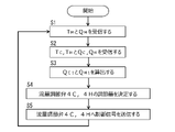
- 4 is a flow chart showing the flow of temperature control and flow rate control of the hot water mixing device according to the embodiment.
- FIG. 3 is a flowchart showing the flow of calculation of each target flow rate in FIG. 2;
- FIG. 3 is a flowchart showing the flow of calculation of each target flow rate in FIG. 2;
- the hot water mixing device 10 is installed in a kitchen or a bathroom.
- the hot water mixing device 10 supplies mixed water at a predetermined temperature and flow rate to a discharge pipe attached to a sink or washing place.
- the hot water mixing device 10, as shown in FIG. 1, includes a water supply pipe 1C, a hot water supply pipe 1H, and a mixing pipe 1M.
- the water supply pipe 1C is connected to the water supply source C, and a water supply channel is formed inside. Water at 20° C., for example, flows through the water supply channel.
- the water supply pipe 1C has a check valve 2C, a temperature sensor 3C, a flow control valve 4C, and a flow sensor 5C in order from upstream to downstream.
- the hot water supply pipe 1H is connected to a hot water supply source H such as a gas water heater, and a hot water supply path is formed inside. Hot water of 60° C., for example, flows through the hot water supply path.
- the hot water supply pipe 1H has a check valve 2H, a temperature sensor 3H, a flow control valve 4H, and a flow sensor 5H in order from the upstream side to the downstream side, like the water supply pipe 1C described above.
- the mixing pipe 1M is connected to the water supply pipe 1C and the hot water supply pipe 1H, and a mixing channel is formed inside.
- Mixed water which is a mixture of water supplied from the water supply channel and hot water supplied from the hot water supply channel, flows through the mixed water channel.
- the mixing pipe 1M has a temperature sensor 3M and an on-off valve 6M in order from upstream to downstream.
- the downstream side of the mixing pipe 1M is connected to various discharge pipes (not shown).
- the temperature sensors 3C, 3H, and 3M are thermistors. Temperature sensors 3C, 3H, 3M detect the temperature of water inside the water supply pipe 1C, the temperature of the hot water inside the hot water supply pipe 1H, and the temperature of the mixed water inside the mixing pipe 1M. The temperature sensors 3C and 3H correspond to part of the cold water side information acquisition section and the hot water side information acquisition section.
- the flow rate control valves 4C and 4H are valve bodies that are rotationally driven by a stepping motor to widen or narrow the flow paths of the water supply path and the hot water supply path to adjust the water side opening degree VPc and the hot water side opening degree VPh. .
- the flow control valves 4C and 4H have the same shape and size.
- the degree of opening of the flow rate control valves 4C and 4H means the extent to which the flow rate control valves 4C and 4H are open, and is the size of the flow path area that changes with the flow rate control valves 4C and 4H.
- the degree of opening of the flow rate control valves 4C and 4H can be grasped from the rotation angle if the flow rate control valves change the flow path area by rotational driving.
- the water side opening degree VPc and the hot water side opening degree VPh are based on one predetermined opening degree, not the difference (change amount) between the opening degrees before and after the flow rate adjustment.
- the flow control valves 4C and 4H regulate the flow rate QC of water flowing through the water supply channel and the flow rate QH of hot water flowing through the hot water supply channel.
- the flow rate control valves 4C and 4H correspond to a cold water side flow rate control section and a hot water side flow rate control section.
- the on-off valve 6M is an electromagnetic valve.
- the on-off valve 6M opens and closes the channel of the mixing water channel to flow or stop the mixed water in the mixing water channel.
- the hot water mixing device 10 includes a setting section 70 and a control section 80 .
- a setting unit 70 is a remote controller installed in a kitchen or a bathroom.
- the setting unit 70 has various operation buttons (not shown) and a display panel for displaying the temperature and flow rate of the mixed water in the mixing channel.
- the setting unit 70 transmits setting information to the control unit 80 .
- the control unit 80 is connected to the temperature sensors 3C, 3H, 3M, the flow sensors 5C, 5H, the flow control valves 4C, 4H, the on-off valve 6M, and the setting unit 70 by wire.
- the control unit 80 receives and stores temperature information detected by the temperature sensors 3C and 3H and flow rate information detected by the flow sensors 5C and 5H.
- the temperature information detected by the temperature sensor 3C and the flow information detected by the flow sensor 5C correspond to water information.
- the temperature information detected by the temperature sensor 3H and the flow information detected by the flow sensor 5H correspond to hot water information.
- the control unit 80 also stores the opening degree VPc on the water side of the flow control valve 4C, the opening degree VPh on the hot water side of the flow control valve 4H, and the open/close state of the on-off valve 6M. Further, the control unit 80 stores in advance how the opening degrees VPc and VPh of the flow control valves 4C and 4H should be adjusted with respect to the target flow rate of the water flowing through the water supply passage and the hot water flowing through the hot water supply passage.
- control unit 80 When the control unit 80 receives setting information for starting or stopping discharge from the setting unit 70, the control unit 80 transmits a control signal to the on-off valve 6M to open and close the on-off valve 6M.
- the control unit 80 calculates the target flow rate of the water flowing through the water supply passage and the hot water flowing through the hot water supply passage based on the setting information of the setting unit 70, the temperature information of the temperature sensors 3C and 3H, and the flow rate information of the flow sensors 5C and 5H. , control signals to the flow control valves 4C and 4H to adjust the opening degrees VPc and VPh of the flow control valves 4C and 4H.
- the controller 80 controls the temperature and flow rate of the mixed water in the mixing flow path, as shown in FIG.
- the control unit 80 receives the set temperature TM and the set flow rate QM of mixed water set by the setting unit 70 (step S1).
- the set temperature TM and the set flow rate QM correspond to set information.
- the control unit 80 detects the current temperature T C of water in the water supply passage detected by the temperature sensors 3C and 3H, the temperature T H of the hot water in the hot water supply passage, and the current temperature T H of the water supply passage detected by the flow rate sensors 5C and 5H.
- the water flow rate QC of the hot water supply passage and the hot water flow rate QH of the hot water supply passage are received (step S2).
- the control unit 80 sets the target flow rate Q C1 , Q C1 , Then, a target flow rate QH1 of hot water to be supplied to the hot water supply passage is calculated (step S3).
- the flow rate QC of water flowing through the water supply channel is the same as the flow rate of water flowing through the flow control valve 4C of the water supply channel.
- the flow rate QH of hot water flowing through the hot water supply passage is the same as the flow rate of hot water flowing through the flow control valve 4H of the hot water supply passage. The details of this calculation method will be described later.
- the control unit 80 adjusts the adjustment amounts of the flow rate control valves 4C and 4H based on the pre-stored opening degrees VPc and VPh of the flow rate control valves 4C and 4H. Determine (step S4).
- the control unit 80 determines the adjustment amounts of the flow control valves 4C and 4H so that the flow rates do not become the same as the target flow rates QC1 and QH1 calculated in step S3. Specifically, the amount of change from the current opening degrees VPc and VPh to the opening degrees VPc and VPh that allows the same flow rate as the target flow rates Q C1 and Q H1 is suppressed to about 80%.
- the control unit 80 transmits control signals to the flow control valves 4C and 4H based on the determined adjustment amounts of the flow control valves 4C and 4H (step S5), and returns to and repeats step S1 of receiving the setting information.
- the number of repetitions may be set to a predetermined number, or may be changed according to the setting information.
- the controller 80 adjusts the flow rate control valves 4C and 4H so that the flow rates are the same as the calculated target flow rates Q C1 and Q H1 in step S4. to decide.
- the method of calculating the target flow rate Q C1 of the water supply passage flow control valve 4C and the target flow rate Q H1 of the hot water supply passage flow control valve 4H is as follows. As shown in FIG. 3, the control unit 80 first determines whether the set temperature TM is lower than the temperature T H of the hot water in the hot water supply passage (step S301). If it is determined in step S301 that the set temperature TM is higher than the hot water temperature TH (determined as No), the control unit 80 calculates the target flow rate QC1 of the flow control valve 4C as zero.
- Step S302 the target flow rate QH1 of the flow control valve 4H is calculated to be the same as the set flow rate QM (Step S303), and the process proceeds to step S4 for determining the adjustment amounts of the flow control valves 4C and 4H. If it is determined in step S301 that the set temperature TM is equal to the hot water temperature T H or that the set temperature TM is lower than the hot water temperature T H ( determined as Yes), the control unit 80 It is determined whether the set temperature TM is higher than the water temperature TC (step S304).
- step S304 If it is determined in step S304 that the set temperature TM is equal to the water temperature TC or that the set temperature TM is higher than the water temperature TC (determined as Yes), the control unit 80 A target flow rate QC1 for the flow control valve 4C is calculated using the following formula 1 (step S307), and a target flow rate QH1 for the flow control valve 4H is calculated using the following formula 2 (step S308).
- Q C1 (T H ⁇ T M ) ⁇ Q M /(T H ⁇ T C ) Equation 1
- Q H1 Q M - Q C1 ... Equation 2
- the control unit 80 determines whether the current temperature T H of the hot water in the hot water supply passage is higher than a predetermined threshold value (step S309).
- the threshold is approximately 40 degrees. If it is determined in step S309 that the temperature T H of the hot water is lower than the threshold value (determined as No), the control unit 80 controls the target flow rate Q C1 calculated in step S307 and the target flow rate Q C1 calculated in step S308. Based on the flow rate QH1 , the process proceeds to step S4 for determining the adjustment amounts of the flow control valves 4C and 4H.
- control unit 80 omits recalculation of the target flow rate, which will be described later.
- step S309 if it is determined that the hot water temperature TH is equal to or higher than the threshold (determined as Yes), the controller 80 controls the water side opening VPc of the flow control valve 4C to It is determined whether it is greater than the hot water side opening VPh of the flow control valve 4H (step S310).
- step S310 If it is determined in step S310 that the water side opening VPc of the flow rate control valve 4C is equal to the hot water side opening VPh of the flow rate control valve 4H or the water side opening VPc is greater than the hot water side opening VPh (Yes is determined), the control unit 80 recalculates and updates the target flow rate QH1 of the flow rate control valve 4H based on the flow rate QC of the water flowing through the flow rate control valve 4C using Equation 3 shown below. (step S311).
- step S3 the control unit 80 controls the flow control valves 4C and 4H based on the target flow rate QC1 of the flow control valve 4C calculated in step S307 and the target flow rate QH1 of the flow control valve 4H calculated and updated in step S311.
- the process proceeds to step S4 for determining the adjustment amount of .
- step S310 If it is determined in step S310 that the water side opening VPc of the flow rate control valve 4C is smaller than the hot water side opening VPh of the flow rate control valve 4H (determined as No), the controller 80 controls the flow rate control valve Based on the flow rate QH of the hot water flowing through the flow control valve 4H, the target flow rate QC1 of 4C is recalculated and updated using the following equation 4 (step S313).
- step S3 (T H ⁇ T M ) ⁇ Q H /(T M ⁇ T C ) Equation 4
- the control unit 80 controls the flow rate control valves 4C and 4H based on the target flow rate QH1 of the flow rate control valve 4H calculated in step S308 and the target flow rate QC1 of the flow rate control valve 4C calculated and updated in step S313.
- the process proceeds to step S4 for determining the adjustment amount of .
- the hot water mixing device 10 of the present embodiment is connected to a water supply source C, and is connected to a water supply pipe 1C having a water supply passage through which water supplied from the water supply source C is formed therein, and a hot water supply source H, and is connected to a hot water supply source H.
- a hot water supply pipe 1H forming a hot water supply channel through which hot water supplied from H is connected to the water supply pipe 1C and the hot water supply pipe 1H, and a mixture in which water supplied from the water supply channel and hot water supplied from the hot water supply channel are mixed.
- a mixing pipe 1M forming a mixing channel through which water flows.
- the hot water mixing device 10 also includes a flow control valve 4C for adjusting the flow rate of water in the water supply channel, and a temperature sensor 3C and a flow sensor 5C for detecting the temperature and flow rate of water in the water supply channel. Further, the hot water mixing device 10 includes a flow control valve 4H for adjusting the flow rate of hot water in the hot water supply channel, and a temperature sensor 3H and a flow sensor 5H for detecting the temperature and flow rate of hot water in the hot water supply channel. The hot water mixing apparatus 10 also includes a setting section 70 for setting the temperature and flow rate of the mixed water in the mixing channel, and a control section 80 for controlling the flow control valves 4C and 4H.
- control unit 80 of the hot water mixing apparatus 10 controls the set temperature T M and set flow rate Q M of the setting unit 70, the temperature T C of the water in the water supply channel obtained from the temperature sensor 3C, and the hot water supply channel obtained from the temperature sensor 3H.
- a target flow rate QC1 of the flow rate control valve 4C and a target flow rate QH1 of the flow rate control valve 4H are calculated based on the hot water temperature TH in the flow rate control valves 4C and 4H. determines and controls the amount of adjustment of As a result, the hot water mixing device 10 can supply mixed water at a temperature and flow rate desired by the user.
- the controller 80 of the hot water mixing device 10 controls the water side opening degree VPc indicating the degree to which the water side flow control valve 4C opens the water supply passage, and the degree to which the hot water side flow control valve 4H opens the hot water passage. is compared with the hot water side opening degree VPh that indicates the degree of opening. Based on the flow rates QC and QH on the larger side of the water side opening degree VPc and the hot water side opening degree VPh , the target flow rates QC1 and QH1 on the smaller opening side are calculated and updated. Based on the target flow rates QC1 and QH1 , the flow control valves 4C and 4H having smaller opening degrees are controlled.
- the hot water mixing device 10 calculates the target flow rates QC1 and QH1 on the side with the small opening degrees VPc and VPh based on the flow rates QC and QH on the side with the large opening degrees VPc and VPh. It is possible to prevent the temperature of the mixed water in the water channel from becoming too high or too low instantaneously. Therefore, the hot water mixing device 10 can perform stable temperature control without using a constant flow valve or the like for detecting pressure fluctuations.
- the controller 80 of the hot water mixing device 10 compares the water side opening degree VPc of the flow control valve 4C with the hot water side opening degree VPh of the flow rate control valve 4H, and determines that the water side opening degree VPc is the hot water side opening degree. degree VPh , the target flow rate QH1 of the hot water side flow control valve 4H is calculated and updated based on the flow rate QC acquired by the water side flow rate sensor 5C, and the updated target flow rate The hot water side flow control valve 4H is controlled based on QH1 .
- the hot water mixing device 10 can perform stable temperature control.
- the controller 80 of the hot water mixing device 10 compares the water side opening degree VPc of the flow control valve 4C with the hot water side opening degree VPh of the flow rate control valve 4H, and the water side opening degree VPc is the hot water side opening degree. If it is determined to be less than VPh , the target flow rate QC1 of the water-side flow control valve 4C is calculated and updated based on the flow rate QH acquired by the hot water-side flow rate sensor 5H, and the updated target flow rate Q The flow control valve 4C on the water side is controlled on the basis of C1 .
- the hot water mixing device 10 can perform stable temperature control.
- the hot water mixing device 10 of the present embodiment has the on-off valve 6M in the mixing pipe 1M, but the mixing pipe 1M may not have the on-off valve.
- the water supply pipe 1C and the hot water supply pipe 1H may have on-off valves, and the flow control valves 4C and 4H of the water supply pipe 1C and the hot water supply pipe 1H have the function of closing the flow paths as on-off valves.
- the water supply pipe 1C and the hot water supply pipe 1H of the present embodiment have flow sensors 5C and 5H, but one of the flow sensors 5C and 5H is omitted, and the mixing pipe 1M has a flow sensor.
- the hot water supply pipe 1H does not have the flow sensor 5H
- the flow rate QH of the hot water in the hot water supply passage is calculated from the flow rate of mixed water detected by the flow sensor of the mixing pipe 1M, and the water detected by the flow sensor 5C of the water supply pipe 1C. It is calculated by subtracting the flow rate QC of (3)
- the control unit 80 of the present embodiment is connected to the flow sensors 5C, 5H, the setting unit 70, etc.
- setting unit 70 and the control unit 80 of the present embodiment set and control the temperature and flow rate of the mixed water
- another setting is to or automatically stop the water supply after discharging the mixed water at a set flow rate.
- Hot water mixing device 1C Water supply pipe (water supply channel) 1H Hot water supply pipe (hot water supply channel) 1M Mixing pipe (mixing water channel) 3C Temperature sensor (part of water side information acquisition unit) 3H Temperature sensor (part of the hot water side information acquisition unit), 4C... flow control valve (water side flow control unit), 4H... flow control valve (hot water side flow control unit), 5C... flow sensor (of the water side information acquisition unit 5H... flow rate sensor (part of hot water side information acquisition part), 70... setting part, 80... control part, C... water supply source, H... hot water supply source, Q M ...
Landscapes
- Engineering & Computer Science (AREA)
- General Engineering & Computer Science (AREA)
- Mechanical Engineering (AREA)
- Chemical & Material Sciences (AREA)
- Thermal Sciences (AREA)
- Combustion & Propulsion (AREA)
- Physics & Mathematics (AREA)
- Health & Medical Sciences (AREA)
- Life Sciences & Earth Sciences (AREA)
- Hydrology & Water Resources (AREA)
- Public Health (AREA)
- Water Supply & Treatment (AREA)
- Domestic Hot-Water Supply Systems And Details Of Heating Systems (AREA)
- Domestic Plumbing Installations (AREA)
Abstract
安定した温度制御ができる湯水混合装置を提供する。 制御部(80)は、流量調節弁(4C)が給水路を開いている大きさを示す水側開度(VPc)と、流量調節弁(4H)が給湯路を開いている大きさを示す湯側開度(VPh)と、を比較し、水側開度(VPc)と湯側開度(VPh)のうち開度が大きい側である給水路及び給湯路のいずれかの流量センサ(5C,5H)が取得した流量(QC,QH)に基づいて、開度が小さい側の給水路及び給湯路のいずれかの流量調節弁(4C,4H)の目標流量(QC1,QH1)を算出して更新し、更新された開度(VPc,VPh)が小さい側の流量調節弁(4C,4H)の目標流量(QC1,QH1)を基準にして開度(VPc,VPh)が小さい側の流量調節弁(4C,4H)を制御する。
Description
本開示は、湯水混合装置に関する。
特許文献1は湯水混合装置を開示している。この湯水混合装置は、給水源から供給された水と給湯源から供給された湯とを混合し、所定の温度及び所定の流量の混合水を吐出する。この湯水混合装置は給水路及び給湯路にダイヤフラム式の定流量弁を配置している。この定流量弁によって、湯水混合装置は、給水源の圧力及び給湯源の圧力の少なくとも一方が所定の圧力より低くなったり、給水源の圧力及び給湯源の圧力の差圧が大きくなったりするなどの圧力変動があった場合、温度制御や流量制御を安定させることができる。
特許文献1の湯水混合装置は、圧力変動によってダイヤフラム式の定流量弁を駆動させるために、圧力室を配置する必要があり、水や湯が流れる流路が複雑になる。
本開示は、このような事情を鑑み、圧力変動を検出する定流量弁などを用いずとも、安定した温度制御ができる湯水混合装置を提供することを目的とする。
本開示の湯水混合装置は、給水源に接続し、前記給水源から供給される水が流れる給水路と、給湯源に接続し、前記給湯源から供給される湯が流れる給湯路と、前記給水路及び前記給湯路に接続し、前記給水路から供給される水及び前記給湯路から供給される湯を混合した混合水が流れる混合水路と、前記給水路に有る水の流量を調節する水側流量調節部と、前記給湯路に有る湯の流量を調節する湯側流量調節部と、前記給水路に有る水の温度及び流量を含む水情報を取得する水側情報取得部と、前記給湯路に有る湯の温度及び流量を含む湯情報を取得する湯側情報取得部と、前記混合水路に有る混合水の温度及び流量を設定する設定部と、前記設定部の設定情報、前記水側情報取得部の水の温度、及び前記湯側情報取得部の湯の温度に基づき、前記水側流量調節部の目標流量、及び前記湯側流量調節部の目標流量を算出し、前記水側流量調節部及び前記湯側流量調節部を制御する制御部と、を備え、前記制御部は、前記水側流量調節部が前記給水路を開いている大きさを示す水側開度と、前記湯側流量調節部が前記給湯路を開いている大きさを示す湯側開度と、を比較し、前記水側開度と前記湯側開度のうち開度が大きい側である前記給水路及び前記給湯路のいずれかの前記情報取得部が取得した流量に基づいて、開度が小さい側の前記給水路及び前記給湯路のいずれかの前記流量調節部の前記目標流量を算出して更新し、更新された前記開度が小さい側の前記流量調節部の前記目標流量を基準にして前記開度が小さい側の前記流量調節部を制御する。
次に、実施形態に係る湯水混合装置について、図面を用いて説明する。湯水混合装置10は、キッチンや浴室に設置される。湯水混合装置10は、シンクや洗い場に取り付けられた吐出管に対し、所定の温度及び流量の混合水を供給する。湯水混合装置10は、図1に示すように、給水管1C、給湯管1H、及び混合管1Mを備えている。
給水管1Cは、給水源Cに接続しており、内部に給水路が形成されている。給水路は例えば20℃の水が流れる。給水管1Cは、上流側から下流側に向かう順番に、逆止弁2C、温度センサ3C、流量調節弁4C、及び流量センサ5Cを有している。
給湯管1Hは、ガス給湯機などの給湯源Hに接続しており、内部に給湯路が形成されている。給湯路は例えば60℃の湯が流れる。給湯管1Hは、前述した給水管1Cと同様に、上流側から下流側に向かう順番に、逆止弁2H、温度センサ3H、流量調節弁4H、及び流量センサ5Hを有している。
混合管1Mは、給水管1C及び給湯管1Hに接続しており、内部に混合水路が形成されている。混合水路は、給水路から供給される水、及び給湯路から供給される湯を混合した混合水が流れる。混合管1Mは、上流側から下流側に向かう順番に、温度センサ3M、及び開閉弁6Mを有している。混合管1Mの下流側は、図示しない各種の吐出管に接続している。
温度センサ3C,3H,3Mは、サーミスタである。温度センサ3C,3H,3Mは、給水管1Cの内部に有る水の温度、給湯管1Hの内部に有る湯の温度、及び混合管1Mの内部に有る混合水の温度を検出する。温度センサ3C,3Hは、水側情報取得部及び湯側情報取得部の一部に対応する。
流量調節弁4C,4Hは、ステッピングモータにより回転駆動し、給水路、及び給湯路の流路を拡げたり狭めたりして水側開度VPc、及び湯側開度VPhを調節する弁体である。流量調節弁4C,4Hは、同一形状、同じ大きさである。ここで、流量調節弁4C,4Hの開度とは、流量調節弁4C,4Hの開いている程度をいい、流量調節弁4C,4Hによって変化する流路面積の大きさである。流量調節弁4C,4Hの開度は、回転駆動によって流路面積を変化させる流量調節弁である場合、回転角度によって把握できる。水側開度VPc及び湯側開度VPhは、流量調節における前後の開度の差(変化量)ではなく、予め定められた一つの開度を基準としている。流量調節弁4C,4Hは、給水路に流れる水の流量QC、及び給湯路に流れる湯の流量QHを調節する。流量調節弁4C,4Hは、水側流量調節部及び湯側流量調節部に対応する。
開閉弁6Mは電磁弁である。開閉弁6Mは、混合水路の流路を開閉して、混合水路に混合水を流したり止めたりする。
流量センサ5C,5Hは、羽根車式の流量計である。流量センサ5C,5Hは、給水路に流れる水、及び給湯路に流れる湯によって羽根車が回転し、その回転数に基づいて、水の流量QC、湯の流量QHを検出する。流量センサ5C,5Hは、水側情報取得部及び湯側情報取得部の一部に対応する。
湯水混合装置10は、設定部70及び制御部80を備えている。設定部70は、キッチンや浴室に設置されたリモコンである。設定部70は、図示しない各種操作ボタンや、混合水路に有る混合水の温度及び流量を表示する表示パネルを有している。使用者は、所望する混合水の温度及び流量の設定値を操作ボタンで入力すると、設定部70は、制御部80へ設定情報を送信する。
制御部80は、温度センサ3C,3H,3M、流量センサ5C,5H、流量調節弁4C,4H、開閉弁6M、及び設定部70とそれぞれ有線で接続している。制御部80は、温度センサ3C,3Hで検出した温度情報、及び流量センサ5C,5Hで検出した流量情報をそれぞれ受信し、記憶している。温度センサ3Cで検出した温度情報、及び流量センサ5Cで検出した流量情報は、水情報に対応する。温度センサ3Hで検出した温度情報、及び流量センサ5Hで検出した流量情報は、湯情報に対応する。また、制御部80は、流量調節弁4Cの水側開度VPc、流量調節弁4Hの湯側開度VPh及び開閉弁6Mの開閉状態をそれぞれ記憶している。さらに、制御部80は、給水路に流す水、及び給湯路に流す湯の目標流量に対し、流量調節弁4C,4Hの開度VPc,VPhをどのくらい調節するかを予め記憶している。
制御部80は、設定部70から吐出開始や吐出停止の設定情報を受信した場合、開閉弁6Mへ制御信号を送信し、開閉弁6Mを開閉する。制御部80は、設定部70の設定情報、温度センサ3C,3Hの温度情報、及び流量センサ5C,5Hの流量情報に基づき、給水路に流す水及び給湯路に流す湯の目標流量を算出し、流量調節弁4C,4Hへ制御信号を送信し、流量調節弁4C,4Hの開度VPc,VPhを調節する。
制御部80は、図2に示すように、混合流路に有る混合水の温度及び流量を制御する。まず、制御部80は、設定部70から設定された混合水の設定温度TM及び設定流量QMを受信する(ステップS1)。設定温度TM及び設定流量QMは、設定情報に対応する。次に、制御部80は、温度センサ3C,3Hで検出した現在の給水路に有る水の温度TC及び給湯路に有る湯の温度TH、流量センサ5C,5Hで検出した現在の給水路の水の流量QC及び給湯路の湯の流量QHを受信する(ステップS2)。次に、制御部80は、設定情報TM,QM、現在の温度情報TC,TH、及び現在の流量情報QC,QHに基づき、給水路に流す水の目標流量QC1、及び給湯路に流す湯の目標流量QH1を算出する(ステップS3)。給水路に流れる水の流量QCは、給水路の流量調節弁4Cに流れる水の流量と同じである。また、給湯路に流れる湯の流量QHは、給湯路の流量調節弁4Hに流れる湯の流量と同じである。この算出方法の詳細は、後述する。
次に、制御部80は、算出した目標流量QC1,QH1に基づき、予め記憶している流量調節弁4C,4Hの開度VPc,VPhに基づいて流量調節弁4C,4Hの調節量を決定する(ステップS4)。制御部80は、ステップS3において算出した目標流量QC1,QH1と同じ流量にならないように、流量調節弁4C,4Hの調節量を決定する。具体的には、現在の開度VPc,VPhから、目標流量QC1,QH1と同じ流量を流せる開度VPc,VPhへの変化量を80%程度に抑える。制御部80は、決定した流量調節弁4C,4Hの調節量に基づき、流量調節弁4C,4Hへ制御信号を送信し(ステップS5)、設定情報を受信するステップS1に戻って繰り返す。繰り返す回数は、所定の回数に定めてもよいし、設定情報に応じて変更できるようにしてもよい。ステップS1からステップS5の繰り返し回数が最後となった場合、制御部80は、ステップS4において、算出した目標流量QC1,QH1と同じ流量となるように、流量調節弁4C,4Hの調節量を決定する。
給水路の流量調節弁4Cの目標流量QC1、及び給湯路の流量調節弁4Hの目標流量QH1の算出方法は、次のとおりである。図3に示すように、制御部80は、まず、設定温度TMが、給湯路に有る湯の温度THよりも低いかを判定する(ステップS301)。ステップS301において、設定温度TMが湯の温度THよりも高いと判定された場合(Noと判定された場合)、制御部80は、流量調節弁4Cの目標流量QC1をゼロと算出し(ステップS302)、流量調節弁4Hの目標流量QH1を設定流量QMと同じと算出し(ステップS303)、流量調節弁4C,4Hの調節量を決定するステップS4へ移る。ステップS301において、設定温度TMが湯の温度THに等しい、若しくは設定温度TMが湯の温度THよりも低いと判定された場合(Yesと判定された場合)、制御部80は、設定温度TMが水の温度TCよりも高いかを判定する(ステップS304)。ステップS304において、設定温度TMが水の温度TCよりも低いと判定された場合(Noと判定された場合)、制御部80は、流量調節弁4Cの目標流量QC1を設定流量QMと同じと算出し(ステップS305)、流量調節弁4Hの目標流量QH1をゼロと算出し(ステップS306)、流量調節弁4C,4Hの調節量を決定するステップS4へ移る。
ステップS304において、設定温度TMが水の温度TCに等しい、若しくは設定温度TMが水の温度TCよりも高いと判定された場合(Yesと判定された場合)、制御部80は、流量調節弁4Cの目標流量QC1を以下に示す式1で算出し(ステップS307)、流量調節弁4Hの目標流量QH1を以下に示す式2で算出する(ステップS308)。
QC1=(TH-TM)×QM/(TH-TC) … 式1
QH1=QM-QC1 … 式2
QC1=(TH-TM)×QM/(TH-TC) … 式1
QH1=QM-QC1 … 式2
次に、制御部80は、現在の給湯路に有る湯の温度THが、所定の閾値よりも高いかを判定する(ステップS309)。閾値は、約40度である。ステップS309において、湯の温度THが閾値よりも低いと判定された場合(Noと判定された場合)、制御部80は、ステップS307において算出した目標流量QC1、及びステップS308において算出した目標流量QH1に基づいて、流量調節弁4C,4Hの調節量を決定するステップS4へ移る。この場合は、給水源Cの圧力、及び給湯源Hの圧力が、所定の圧力よりも低かったり、差圧が大きかったりしても、混合流路に有る混合水の温度が急激に変化する恐れがないため、制御部80は、後述する目標流量の再算出を省略する。
ステップS309において、湯の温度THが閾値に等しい、若しくは閾値よりも高いと判定された場合(Yesと判定された場合)、制御部80は、流量調節弁4Cの水側開度VPcが、流量調節弁4Hの湯側開度VPhよりも大きいか判定する(ステップS310)。ステップS310において、流量調節弁4Cの水側開度VPcが流量調節弁4Hの湯側開度VPhに等しい、若しくは水側開度VPcが湯側開度VPhよりも大きいと判定された場合(Yesと判定された場合)、制御部80は、流量調節弁4Hの目標流量QH1を流量調節弁4Cに流れている水の流量QCに基づいて、以下に示す式3で再度算出して更新する(ステップS311)。
QH1=(TM-TC)×QC/(TH‐TM) … 式3
次に、制御部80は、ステップS307において算出した流量調節弁4Cの目標流量QC1、及びステップS311において算出して更新した流量調節弁4Hの目標流量QH1に基づき、流量調節弁4C,4Hの調節量を決定するステップS4へ移る。
QH1=(TM-TC)×QC/(TH‐TM) … 式3
次に、制御部80は、ステップS307において算出した流量調節弁4Cの目標流量QC1、及びステップS311において算出して更新した流量調節弁4Hの目標流量QH1に基づき、流量調節弁4C,4Hの調節量を決定するステップS4へ移る。
ステップS310において、流量調節弁4Cの水側開度VPcが流量調節弁4Hの湯側開度VPhよりも小さいと判定された場合(Noと判定された場合)、制御部80は、流量調節弁4Cの目標流量QC1を流量調節弁4Hに流れている湯の流量QHに基づいて、以下に示す式4で再度算出して更新する(ステップS313)。
QC1=(TH-TM)×QH/(TM-TC) … 式4
制御部80は、次に、ステップS308において算出した流量調節弁4Hの目標流量QH1、及びステップS313において算出して更新した流量調節弁4Cの目標流量QC1に基づき、流量調節弁4C,4Hの調節量を決定するステップS4へ移る。
QC1=(TH-TM)×QH/(TM-TC) … 式4
制御部80は、次に、ステップS308において算出した流量調節弁4Hの目標流量QH1、及びステップS313において算出して更新した流量調節弁4Cの目標流量QC1に基づき、流量調節弁4C,4Hの調節量を決定するステップS4へ移る。
次に、本実施形態の作用及び効果について、説明する。本実施形態の湯水混合装置10は、給水源Cに接続し、内部に給水源Cから供給される水が流れる給水路を形成した給水管1Cと、給湯源Hに接続し、内部に給湯源Hから供給される湯が流れる給湯路を形成した給湯管1Hと、給水管1C及び給湯管1Hに接続し、内部に給水路から供給される水及び給湯路から供給される湯を混合した混合水が流れる混合水路を形成した混合管1Mと、を備えている。また、湯水混合装置10は、給水路に有る水の流量を調節する流量調節弁4Cと、給水路に有る水の温度及び流量を検出する温度センサ3C及び流量センサ5Cと、を備えている。さらに、湯水混合装置10は、給湯路に有る湯の流量を調節する流量調節弁4Hと、給湯路に有る湯の温度及び流量を検出する温度センサ3H及び流量センサ5Hと、を備えている。また、湯水混合装置10は、混合水路に有る混合水の温度及び流量を設定する設定部70と、流量調節弁4C,4Hを制御する制御部80と、を備えている。さらに、湯水混合装置10の制御部80は、設定部70の設定温度TM及び設定流量QM、温度センサ3Cから取得した給水路に有る水の温度TC、温度センサ3Hから取得した給湯路に有る湯の温度THに基づき、流量調節弁4Cの目標流量QC1、及び流量調節弁4Hの目標流量QH1を算出し、目標流量QC1,QH1に基づき、流量調節弁4C,4Hの調節量を決定して制御する。これにより、湯水混合装置10は、使用者が所望する温度及び流量の混合水を供給することができる。
湯水混合装置10の制御部80は、水側の流量調節弁4Cが給水路を開いている大きさを示す水側開度VPcと、湯側の流量調節弁4Hが給湯路を開いている大きさを示す湯側開度VPhと、を比較する。水側開度VPcと湯側開度VPhのうち開度が大きい側の流量QC,QHに基づいて、開度が小さい側の目標流量QC1,QH1を算出して更新し、更新された目標流量QC1,QH1を基準にして開度が小さい側の流量調節弁4C,4Hを制御する。ここで、開度が大きい側の流量調節弁は、開度が小さい側の流量調節弁よりも、目標の開度に達するまでの時間が多くかかる場合がある。しかしながら、湯水混合装置10は、開度VPc,VPhが大きい側の流量QC,QHに基づいて、開度VPc,VPhが小さい側の目標流量QC1,QH1を算出することによって、混合水路に有る混合水の温度が瞬間的に高くなりすぎたり低くなりすぎたりすることを抑えることができる。よって、湯水混合装置10は、圧力変動を検出する定流量弁などを用いずとも、安定した温度制御ができる。
具体的には、湯水混合装置10の制御部80は、流量調節弁4Cの水側開度VPcと流量調節弁4Hの湯側開度VPhとを比較し、水側開度VPcが湯側開度VPhよりも大きいと判定した場合、水側の流量センサ5Cが取得した流量QCに基づいて、湯側の流量調節弁4Hの目標流量QH1を算出して更新し、更新された目標流量QH1を基準にして湯側の流量調節弁4Hを制御する。これにより、給湯路に有る湯の流量QHは、給水路に有る水の流量QCと比較して急激に多くなったり、若しくは少なくなったりすることがなく、混合水路に有る混合水の温度が高温側、若しくは低温側に急激に変化することを抑えることができる。よって、湯水混合装置10は、安定した温度制御ができる。
また、湯水混合装置10の制御部80は、流量調節弁4Cの水側開度VPcと流量調節弁4Hの湯側開度VPhとを比較し、水側開度VPcの方が湯側開度VPhよりも小さいと判定した場合、湯側の流量センサ5Hが取得した流量QHに基づいて、水側の流量調節弁4Cの目標流量QC1を算出して更新し、更新された目標流量QC1を基準にして水側の流量調節弁4Cを制御する。これにより、給水路に有る水の流量QCは、給湯路に有る湯の流量QHと比較して急激に多くなったり、若しくは少なくなったりすることがなく、混合水路に有る混合水の温度が高温側、若しくは低温側に急激に変化することを抑えることができる。よって、湯水混合装置10は、安定した温度制御ができる。
本開示は、上記記述及び図面によって説明した実施形態に限定されるものではなく、次のような実施形態も本開示の技術的範囲に含まれる。
(1)本実施形態の湯水混合装置10は、混合管1Mに開閉弁6Mを有しているが、混合管1Mに開閉弁がなくてもよい。この場合、給水管1Cと給湯管1Hが開閉弁を有していてもよいし、給水管1Cと給湯管1Hの流量調節弁4C,4Hが、開閉弁として各流路を閉じる機能を有していてもよい。
(2)本実施形態の給水管1C及び給湯管1Hは、流量センサ5C,5Hを有しているが、流量センサ5C,5Hのいずれか一方を省略し、混合管1Mが流量センサを有していてもよい。例えば、給湯管1Hに流量センサ5Hがない場合、給湯路に有る湯の流量QHは、混合管1Mの流量センサで検出した混合水の流量から、給水管1Cの流量センサ5Cで検出した水の流量QCを差分することにより、算出する。
(3)本実施形態の制御部80は、流量センサ5C,5Hや設定部70などと有線で接続しているが、一部または全部と無線で電気的に接続していてもよい。
(4)本実施形態の設定部70及び制御部80は、混合水の温度及び流量を設定して制御することを説明したが、その他の設定として、給湯路に滞留して冷めてしまった湯を排出したり、設定した流量の混合水を吐出した後に、自動で止水したりする制御など、各種の制御をするようにしてもよい。
(1)本実施形態の湯水混合装置10は、混合管1Mに開閉弁6Mを有しているが、混合管1Mに開閉弁がなくてもよい。この場合、給水管1Cと給湯管1Hが開閉弁を有していてもよいし、給水管1Cと給湯管1Hの流量調節弁4C,4Hが、開閉弁として各流路を閉じる機能を有していてもよい。
(2)本実施形態の給水管1C及び給湯管1Hは、流量センサ5C,5Hを有しているが、流量センサ5C,5Hのいずれか一方を省略し、混合管1Mが流量センサを有していてもよい。例えば、給湯管1Hに流量センサ5Hがない場合、給湯路に有る湯の流量QHは、混合管1Mの流量センサで検出した混合水の流量から、給水管1Cの流量センサ5Cで検出した水の流量QCを差分することにより、算出する。
(3)本実施形態の制御部80は、流量センサ5C,5Hや設定部70などと有線で接続しているが、一部または全部と無線で電気的に接続していてもよい。
(4)本実施形態の設定部70及び制御部80は、混合水の温度及び流量を設定して制御することを説明したが、その他の設定として、給湯路に滞留して冷めてしまった湯を排出したり、設定した流量の混合水を吐出した後に、自動で止水したりする制御など、各種の制御をするようにしてもよい。
10…湯水混合装置、1C…給水管(給水路)、1H…給湯管(給湯路)、1M…混合管(混合水路)、3C…温度センサ(水側情報取得部の一部)、3H…温度センサ(湯側情報取得部の一部)、4C…流量調節弁(水側流量調節部)、4H…流量調節弁(湯側流量調節部)、5C…流量センサ(水側情報取得部の一部)、5H…流量センサ(湯側情報取得部の一部)、70…設定部、80…制御部、C…給水源、H…給湯源、QM…設定流量(設定情報の一部)、TM…設定温度(設定情報の一部)、QC…給水路に有る水の流量(水情報の一部)、TC…給水路に有る水の温度(水情報の一部)、QH…給湯路に有る湯の流量(湯情報の一部)、TH…給湯路に有る湯の温度(湯情報の一部)、QC1…給水路に流す水の目標流量、QH1…給湯路に流す湯の目標流量、VPc…水側開度、VPh…湯側開度
Claims (1)
- 給水源に接続し、前記給水源から供給される水が流れる給水路と、
給湯源に接続し、前記給湯源から供給される湯が流れる給湯路と、
前記給水路及び前記給湯路に接続し、前記給水路から供給される水及び前記給湯路から供給される湯を混合した混合水が流れる混合水路と、
前記給水路に有る水の流量を調節する水側流量調節部と、
前記給湯路に有る湯の流量を調節する湯側流量調節部と、
前記給水路に有る水の温度及び流量を含む水情報を取得する水側情報取得部と、
前記給湯路に有る湯の温度及び流量を含む湯情報を取得する湯側情報取得部と、
前記混合水路に有る混合水の温度及び流量を設定する設定部と、
前記設定部の設定情報、前記水側情報取得部の水の温度、及び前記湯側情報取得部の湯の温度に基づき、前記水側流量調節部の目標流量、及び前記湯側流量調節部の目標流量を算出し、前記水側流量調節部及び前記湯側流量調節部を制御する制御部と、を備え、
前記制御部は、前記水側流量調節部が前記給水路を開いている大きさを示す水側開度と、前記湯側流量調節部が前記給湯路を開いている大きさを示す湯側開度と、を比較し、前記水側開度と前記湯側開度のうち開度が大きい側である前記給水路及び前記給湯路のいずれかの前記情報取得部が取得した流量に基づいて、開度が小さい側の前記給水路及び前記給湯路のいずれかの前記流量調節部の前記目標流量を算出して更新し、更新された前記開度が小さい側の前記流量調節部の前記目標流量を基準にして前記開度が小さい側の前記流量調節部を制御する湯水混合装置。
Applications Claiming Priority (2)
| Application Number | Priority Date | Filing Date | Title |
|---|---|---|---|
| JP2021-050891 | 2021-03-25 | ||
| JP2021050891A JP7671607B2 (ja) | 2021-03-25 | 2021-03-25 | 湯水混合装置 |
Publications (1)
| Publication Number | Publication Date |
|---|---|
| WO2022201607A1 true WO2022201607A1 (ja) | 2022-09-29 |
Family
ID=83395271
Family Applications (1)
| Application Number | Title | Priority Date | Filing Date |
|---|---|---|---|
| PCT/JP2021/036779 Ceased WO2022201607A1 (ja) | 2021-03-25 | 2021-10-05 | 湯水混合装置 |
Country Status (2)
| Country | Link |
|---|---|
| JP (1) | JP7671607B2 (ja) |
| WO (1) | WO2022201607A1 (ja) |
Citations (6)
| Publication number | Priority date | Publication date | Assignee | Title |
|---|---|---|---|---|
| JPS62118176A (ja) * | 1985-11-18 | 1987-05-29 | Matsushita Electric Ind Co Ltd | 湯水混合装置 |
| JPS631870A (ja) * | 1986-06-20 | 1988-01-06 | Matsushita Electric Ind Co Ltd | 湯水混合装置 |
| JPS63304841A (ja) * | 1987-06-02 | 1988-12-13 | 株式会社ヨロズ | 湯水混合装置 |
| JPH01159547A (ja) * | 1987-12-14 | 1989-06-22 | Noritz Corp | 湯水混合装置 |
| US6024290A (en) * | 1997-03-25 | 2000-02-15 | Dosani; Nazir | Fluid tempering system |
| JP2008292020A (ja) * | 2007-05-22 | 2008-12-04 | Mitsubishi Electric Corp | 貯湯式給湯装置 |
Family Cites Families (1)
| Publication number | Priority date | Publication date | Assignee | Title |
|---|---|---|---|---|
| JP6304623B2 (ja) | 2014-02-12 | 2018-04-04 | パナソニックIpマネジメント株式会社 | 湯水混合装置 |
-
2021
- 2021-03-25 JP JP2021050891A patent/JP7671607B2/ja active Active
- 2021-10-05 WO PCT/JP2021/036779 patent/WO2022201607A1/ja not_active Ceased
Patent Citations (6)
| Publication number | Priority date | Publication date | Assignee | Title |
|---|---|---|---|---|
| JPS62118176A (ja) * | 1985-11-18 | 1987-05-29 | Matsushita Electric Ind Co Ltd | 湯水混合装置 |
| JPS631870A (ja) * | 1986-06-20 | 1988-01-06 | Matsushita Electric Ind Co Ltd | 湯水混合装置 |
| JPS63304841A (ja) * | 1987-06-02 | 1988-12-13 | 株式会社ヨロズ | 湯水混合装置 |
| JPH01159547A (ja) * | 1987-12-14 | 1989-06-22 | Noritz Corp | 湯水混合装置 |
| US6024290A (en) * | 1997-03-25 | 2000-02-15 | Dosani; Nazir | Fluid tempering system |
| JP2008292020A (ja) * | 2007-05-22 | 2008-12-04 | Mitsubishi Electric Corp | 貯湯式給湯装置 |
Also Published As
| Publication number | Publication date |
|---|---|
| JP2022148985A (ja) | 2022-10-06 |
| JP7671607B2 (ja) | 2025-05-02 |
Similar Documents
| Publication | Publication Date | Title |
|---|---|---|
| EP3483690B1 (en) | A method for controlling a fluid flow through a valve | |
| CN111954741B (zh) | 控制装置和方法以及水龙头 | |
| EP3106764B1 (en) | Hot and cold water mixing device | |
| CN104697387A (zh) | 混水器控制方法及装置 | |
| TWI907486B (zh) | 流量控制裝置及方法以及流體供給系統 | |
| US20240360654A1 (en) | Device and method for controlling faucet, and faucet | |
| WO2022201607A1 (ja) | 湯水混合装置 | |
| JP7296289B2 (ja) | 湯水混合装置 | |
| JP7296290B2 (ja) | 湯水混合装置 | |
| CN116339408A (zh) | 一种花洒智能恒温控制器及花洒恒温出水控制方法 | |
| JP6187911B2 (ja) | 吐水装置 | |
| KR101856980B1 (ko) | 온수 공급 장치 및 상기 온수 공급 장치를 구비한 비데 | |
| CN110107810B (zh) | 一种出水温控方法、装置及供水装置 | |
| CN116105374B (zh) | 热水器的控制方法 | |
| JP6299382B2 (ja) | 湯水混合装置 | |
| JP2025167024A (ja) | 湯水混合装置 | |
| KR102548534B1 (ko) | 수전 제어 장치 및 방법, 그리고 수전 | |
| JP2016186764A (ja) | 湯水混合装置 | |
| JP4234690B2 (ja) | 燃焼装置 | |
| JP2010196404A (ja) | 湯水混合装置 | |
| JP2025137202A (ja) | 水栓装置 | |
| JP2023000718A (ja) | ガス燃焼装置 | |
| JP3248137B2 (ja) | 湯水混合装置 | |
| JP2020085335A (ja) | 給湯装置 | |
| JP2025137329A (ja) | 水栓装置 |
Legal Events
| Date | Code | Title | Description |
|---|---|---|---|
| 121 | Ep: the epo has been informed by wipo that ep was designated in this application |
Ref document number: 21933205 Country of ref document: EP Kind code of ref document: A1 |
|
| NENP | Non-entry into the national phase |
Ref country code: DE |
|
| 122 | Ep: pct application non-entry in european phase |
Ref document number: 21933205 Country of ref document: EP Kind code of ref document: A1 |