WO2022201335A1 - エレベータの非接触式ボタン登録装置 - Google Patents
エレベータの非接触式ボタン登録装置 Download PDFInfo
- Publication number
- WO2022201335A1 WO2022201335A1 PCT/JP2021/012100 JP2021012100W WO2022201335A1 WO 2022201335 A1 WO2022201335 A1 WO 2022201335A1 JP 2021012100 W JP2021012100 W JP 2021012100W WO 2022201335 A1 WO2022201335 A1 WO 2022201335A1
- Authority
- WO
- WIPO (PCT)
- Prior art keywords
- distance
- button
- registration
- elevator
- map
- Prior art date
- Legal status (The legal status is an assumption and is not a legal conclusion. Google has not performed a legal analysis and makes no representation as to the accuracy of the status listed.)
- Ceased
Links
Images



Classifications
-
- B—PERFORMING OPERATIONS; TRANSPORTING
- B66—HOISTING; LIFTING; HAULING
- B66B—ELEVATORS; ESCALATORS OR MOVING WALKWAYS
- B66B1/00—Control systems of elevators in general
- B66B1/34—Details, e.g. call counting devices, data transmission from car to control system, devices giving information to the control system
- B66B1/46—Adaptations of switches or switchgear
Definitions
- the present invention relates to a non-contact elevator button registration device for registering the direction of a destination floor or a destination floor.
- non-contact car operating panel a non-contact sensor is used so that the user can register the destination floor without contact. Since this non-contact type sensor is incorporated and arranged in the vicinity of the conventional contact type registration button, it is necessary to design and manufacture a dedicated car operating panel body. In other words, the conventional car operating panel cannot be used with the non-contact car operating panel, and it is necessary to change to a new dedicated non-contact car operating panel. Therefore, there is a problem that it is technically difficult to incorporate a non-contact button registration device by using an existing elevator car operating panel.
- the present invention has been made to solve the above problems, and its object is to provide a non-contact button registration device that can use the conventional registration button body provided in the car or at the landing. It is to be. Another object of the present invention is to provide a non-contact type button registration device that realizes a non-contact type registration button that can be used as a registration button provided in an existing elevator car or hall with minimal increase in cost.
- each row of registration buttons is positioned at a predetermined distance in the vertical direction from the front surface of a registration button main body provided in an elevator car or hall.
- the distance measurement sensor that measures the first distance to the fingertip of the user detected on the front part of the registration button body, and the second distance between the front part of the registration button body and the distance measurement sensor
- a first distance and a second distance are calculated by comparing a map in which registration information of buttons is defined, a memory in which the map is stored, and a first distance to the fingertip of the customer measured by the distance measurement sensor against the map. and a processing means for outputting registration information defined as the second distance when the two match.
- the present invention provides a non-contact elevator button registration system that utilizes prior art registration buttons in the elevator car or at the landing.
- a non-contact button registration device for an elevator that can be used as a registration button provided in an existing elevator car or hall with minimal cost increase.
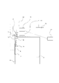
- FIG. 1 is a perspective view showing an elevator non-contact button registration device (whole) according to Embodiment 1 of the present invention
- FIG. 1 is a side view showing the non-contact button registration device (whole) of the elevator of FIG. 1 according to Embodiment 1 of the present invention
- FIG. 1 is an enlarged view (front view) showing a main part of the contactless elevator button registration device of FIG. 1 according to Embodiment 1 of the present invention
- FIG. FIG. 3 is an enlarged view (side view) showing a main part of the contactless elevator button registration device of FIG. 2 according to Embodiment 1 of the present invention
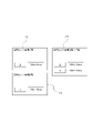
- FIG. 1 is a schematic diagram showing a map of an elevator non-contact button registration device according to Embodiment 1 of the present invention
- FIG. 2 is a front view showing an elevator non-contact button registration device (overall) according to Embodiment 2 of the present invention
- FIG. 5 is a schematic diagram showing a map of the elevator non-contact button registration device according to Embodiment 2 of the present invention
- FIG. 11 is an enlarged view (front view) showing a main part of an elevator non-contact button registration device according to Embodiment 3 of the present invention
- FIG. 11 is a side view showing a non-contact elevator button registration device (overall) according to Embodiment 4 of the present invention
- Embodiment 1. 1 to 5 relate to Embodiment 1 of the present invention
- FIG. 1 is a perspective view showing a non-contact button registration device 1 (whole) for an elevator
- FIG. 3 is an enlarged view (front view) showing essential parts of the contact button registration device 1
- FIG. 4 is an enlarged view (side view) showing the main part of the non-contact button registration device 1 for elevators in FIG. 2
- FIG. 5 is a schematic diagram showing a map of the non-contact button registration device 1 for elevators.
- a car 3 as shown in FIG. 1 is provided in a hoistway (not shown) provided in a building in which an elevator is installed.
- the car 3 is arranged so as to be able to ascend and descend within the hoistway.
- a doorway 4 is provided in the front part of the car 3 .
- a car operating panel 2 is installed on one side wall of the doorway 4 .
- FIG. 1 shows the case where the in-car operating panel 2 is installed on one side wall.
- the in-car operation panel 2 has an operation button 5. - ⁇ The operation button 5 is operated by the user in the car 3 .
- the operation buttons 5 provided on the car operating panel 2 are a destination floor button 51 and a door open button 52, and a destination floor button 53 and a door close button 54 here.
- the destination floor buttons 51 are composed of a plurality of buttons corresponding to the destination floors of the car 3 respectively.
- a plurality of destination floor buttons 51, 53, door open button 52, and door close button 54 are arranged in a matrix here.
- the operation buttons 5 are arranged in two columns, one column of destination floor buttons 51 and door open buttons 52 and one column of destination floor buttons 53 and door close buttons 54 .
- Each of the operation buttons 5 has an operation surface portion that is the target of the user's operation of the operation button 5 .
- the shape of this operation surface portion is circular here.
- the in-car operating panel 2 includes a display section 21 .
- the display unit 21 displays various types of information regarding the operating status of the car 3 .
- the information displayed on the display unit 21 specifically includes, for example, the driving direction of the car 3, the current position of the car 3, and the like.
- a distance measuring sensor 8 is provided between the ceiling 6 and the wall surface 7 inside the car 3 .
- the distance measurement sensor 8 has a distance measurement sensor 81 arranged for the destination floor button 51 and the door open button 52 , and a distance measurement sensor 82 arranged for the destination floor button 53 and the door close button 54 .
- the distance measurement sensor 81 and the distance measurement sensor 82 are arranged at a predetermined distance from the front surface of the operation button 5 in the vertical upward direction.
- the predetermined distance is a range within which the distance measuring sensor 81 and the distance measuring sensor 82 can detect the fingertip 9 of the user operating the car operating panel 2, and This distance is uniquely determined by the size or the like.
- the distance measurement sensor 81 and the distance measurement sensor 82 are optical and measure distance by triangulation.
- the distance measuring sensor 81 and the distance measuring sensor 82 are provided with a light projecting part 11 for emitting the detection beam 10 and a light receiving part 13 for receiving the reflected light 12 of the detection beam 10 reflected from the object to be measured.
- the distance measuring sensor 81 and the distance measuring sensor 82 constantly irradiate the detection beams 10 vertically downward from the upper part of the in-car operating panel 2 toward the front part of the operation button 5 .
- the fingertip 9 When the passenger's fingertip 9 approaches the front surface of the destination floor button 51 or the door open button 52, the destination floor button 53 or the door close button 54, the fingertip 9 is irradiated with the detection beam 10 from the light projector 11. At this time, the light receiving unit 13 receives the reflected light 12 from the fingertip 9, and calculation processing is performed inside the distance measuring sensor 81 or the distance measuring sensor 82 according to the change amount, intensity, etc. of the reflected light 12. A first distance between the fingertip 9 and the distance measurement sensor 81 or the distance measurement sensor 82 can be measured.
- the distance measurement sensor 81 and the distance measurement sensor 82 are each connected to the processing means 14 , and the distance value measured by the distance measurement sensor 81 or the distance measurement sensor 82 is output to the processing means 14 .
- Distance measurement sensors 81 and 82, a memory 15, and an elevator control panel 16 are interconnected to the processing means 14.
- FIG. The processing means 14 has a function of performing data communication with these connected devices and performing calculation and control processing based on the communicated data.
- the memory 15 stores a map 17 in which the floor name of the registration button 5 is defined according to the second distance between the front surface of the main body of the registration button 5 and the distance measuring sensor 8 .
- the map 17 includes a map 171 including registration information such as the floor names of odd-numbered floors such as “1st floor” or “3rd floor” for the destination floor button 51 and the door open button 52, and "2nd floor” for the destination floor button 53.
- a map 172 including registration information such as floor names of even-numbered floors such as "fourth floor” and door close button 54 is set.
- a map 171 is a map for collating the first distance measured by the distance measuring sensor 81
- a map 172 is a map for collating the first distance measured by the distance measuring sensor 82 .
- the processing means 14 communicates with the memory 15 and compares the measured first distance with the map 17 . If the collated first distance matches the second distance, the floor name defined in the second distance of the map 17 or the door open button 52 or the door close button 54 is output to the control panel 16 .
- Embodiment 1 configured as described above will be described.
- the user approaches the front part of the "third floor” of the destination floor button 51 and brings the fingertip 9 close to the fingertip 9.
- a detection beam 10 is emitted from the portion 11 .
- the light receiving portion 13 of the distance measuring sensor 81 receives the reflected light 12 from the fingertip 9 irradiated with the detection beam 10 , and the distance measuring sensor 81 detects the amount of change and intensity of the received reflected light 12 .
- the first distance "1110 mm" between the fingertip 9 and the distance measuring sensor 81 is measured.
- the distance measurement sensor 81 outputs the measured first distance “1110 mm” to the processing means 14 .
- the processing means 14 mutually communicates with the memory 15 based on the input first distance “1110 mm”, and collates the distance matching the first distance “1110 mm” from the map 171.
- FIG. When the measured first distance “1110 mm” and the second distance on the map 171 match, the processing means 14 sets "floor name: 3rd floor” defined in the second distance "1110 mm” on the map 171. Output to the control panel 16 .
- the control panel 16 When “floor name: 3rd floor” is input from the processing means 14, the control panel 16 performs internal processing based on “floor name: 3rd floor”, and sends the in-car operation panel 2 to the destination floor. Instruction information is output so that the same processing as when the button 51 "third floor” is pressed is performed. In the car operation panel 2, internal processing is performed based on the instruction information "floor name: 3rd floor” input from the control panel 16, and "3rd floor” of the destination floor button 51 is registered. to light up the 3rd floor.
- each row of the operation button 5 is positioned vertically apart from the front surface of the operation button 5 provided in the car 3 of the elevator with a predetermined distance. and a distance measuring sensor 8 for measuring a first distance to the user's fingertip 9 detected on the front surface of the operation button 5 main body, and a second distance measuring sensor 8 between the front surface of the operation button 5 main body and the distance measuring sensor 8.
- a map 17 in which the floor name of the operation button 5 is defined according to the distance a memory 15 storing the map 17, and a map 17 showing the first distance to the fingertip 9 of the passenger measured by the distance measuring sensor 8. and a processing means 14 for outputting the floor name defined in the second distance when the first distance and the second distance match with each other. It is possible to realize the non-contact button registration device 1 for an elevator whose main body can be used.
- the distance measuring sensor 81 and the distance measuring sensor 82 are installed between the ceiling inside the car 3 and the inner wall surface 7 of the car 3, so that when using the car operation panel 2, the distance measuring sensor It is possible to realize the non-contact elevator button registration device 1 in which the conventional car operation panel 2 main body can be used without making the 81 and the distance measurement sensor 82 conspicuous.
- Embodiment 2. 6 and 7 illustrate a non-contact button registration device 18 according to Embodiment 2 of the present invention, which is provided at a hall 19.
- the hall button 20 differs from the hall button 20 in that it has the hall button 20, and the same reference numerals are given to the other similar parts, and the description thereof is omitted.
- a hall button 20 as shown in FIG. 6 is provided in a hall 19 provided in a building in which an elevator is installed.
- the hall button 20 is operated by a hall user.
- the hall buttons 20 are an upward button 201 and a downward button 202 here.
- the up button 201 and the down button 202 are arranged in a line here.
- Each of the up button 201 and the down button 202 has an operation surface portion that is targeted for operation by the user. The shape of this operation surface portion is circular here.
- a distance measurement sensor 8 is provided above the boarding point button 20, and is arranged at a predetermined distance vertically upward from the front surfaces of the up button 201 and the down button 202.
- the predetermined distance is a range within which the distance measuring sensor 8 can detect the fingertip 9 of the user who operates the hall button 20, and is uniquely determined by the size of the hall 19 where the hall button 20 is arranged. distance.
- the memory 15 stores a map in which the up button 201 and the down button 202 are defined for each hall according to the second distance between the front part of the main body of the up button 201 and the down button 202 and the distance measuring sensor 81. 173 to 155 are stored.
- the maps 173 to 155 include registration information such as "upward direction” and "downward direction” for each of the 1st to 8th floors of the hall.
- the detection beam 10 is emitted from the light projecting part 11 of the distance measuring sensor 8 to the fingertip 9. be irradiated.
- the light-receiving unit 13 receives the reflected light 12 from the fingertip 9 irradiated with the detection beam 10, and internal calculation processing is performed according to the amount of change and intensity of the received reflected light 12, so that the fingertip A first distance "1310 mm" between 9 and the distance measuring sensor 8 is measured.
- the distance measurement sensor 8 outputs the measured floor name “second floor” and the first distance “1310 mm” to the processing means 14 .
- the processing means 14 performs mutual communication with the memory 15 based on the input floor name “2nd floor” and the first distance “1310 mm”, and selects a map 174 of the floor name "2nd floor” from the maps 173 to 155. to the first distance "1310 mm".
- the processing means 14 instructs the control panel 16 to move the "downward direction" defined in the second distance "1310 mm” on the map 174. Output.
- control panel 16 When "2nd floor” and “downward direction” are input from the processing means 14, the control panel 16 performs internal processing based on the “2nd floor” and “downward direction”. Instruction information is output to perform the same processing as when the direction button 202 is pressed.
- the hall button 20 on the second floor performs internal processing based on the instruction information "down" input from the control panel 16, the down button 202 is registered, and the "down” of the down button 202 is lit. .
- the registration button is the hall button 20 provided in the hall 19 of the elevator. 18 can be realized.
- FIG. 8 illustrates a non-contact button registration device 21 according to Embodiment 3 of the present invention. The difference is that a guide path 22 is provided to limit the detection range of the sensor.
- the guide paths 22 are provided below the light projecting portions 11 of the distance measuring sensor 8, and the guide paths 22 through which the detection beams 10 emitted from the light projecting portions 11 pass are formed. At both ends of the guide path 22 in the width direction, light shielding members 23 for blocking the detection beam 10 in the width direction are arranged. Therefore, the width of the detection beam 10 after passing through the guide path 22 (solid line) is slightly smaller than the original width (chain line).
- the detection range of the detection beam 10 after passing through the guideway 22 is the front surface of the destination floor button 51 and the middle position of the distance from the front surface of the destination floor button 51 to the destination floor button 53. Limited. Further, in this detection range, the shape and mounting position of the guideway 22 are adjusted in advance so that the detection beam 10 is not irradiated from this intermediate position to the destination floor button 53 side.
- the guide path 22 is provided below the light projecting section 11 for irradiating the detection beam 10 of the distance measurement sensor 8 and through which the detection beam 10 passes. Since the guideway 22 is provided with light shielding members 23 for blocking both ends of the detection beam 10 in the width direction, the detection range of the detection beam 10 passing through the guideway 22 is limited to the front surface of the destination floor button 51. Further, the range is limited to the middle position of the distance from the front surface of the destination floor button 51 to the destination floor button 53 adjacent to the destination floor button 51 . As a result, the contactless elevator button registration device 21 capable of preventing erroneous detection can be realized without increasing the directional performance of the distance measurement sensor 8 .
- FIG. 9 illustrates a non-contact button registration device 24 according to Embodiment 4 of the present invention.
- the non-contact button registration device 24 according to Embodiment 4 of the present invention replaces an existing elevator car control panel. It differs in that it has a modification map 25 (not shown) used to implement a non-contact button registration device 24 and a registration mode 26 (not shown). The same symbols are given to the parts, and the explanation is omitted.
- the modification map 25 includes a third distance from the front surface of the registration button main body provided in the car of the existing elevator to the distance measurement sensor 8 arranged at a predetermined distance in the vertical direction, It is a map capable of registering the registration information of the registration button provided in the car of the existing elevator that defines the third distance.
- the basic structure of the repair map 25 is the same as the map 17 of the first embodiment.
- the processing means 14 is connected to a maintenance terminal 27 which is connected to the control panel 16 to perform elevator maintenance and the like.
- the registration mode 26 is a mode in which the maintenance terminal 27 is used to activate the registration work of the repair map 25 to the processing means 14 .
- the repair map 25 is used when performing a registration operation for registering the third distance from the maintenance terminal 27 and the registration information of the operation buttons of the existing car operating panel.
- the contents registered in the repair map 25 using the maintenance terminal 27 are stored in the memory 15 via the processing means 14 .
- Embodiment 4 configured as described above.
- the user installs the distance measuring sensor 8, the processing means 14, and the memory 15 in the car in which the existing car operating panel is installed. connect as possible.
- the maintenance terminal 27 is connected to the processing means 14 and set so as to be mutually communicable with the memory 15 and the control panel 16 , and the registration mode 26 is started from this maintenance terminal 27 .
- the registration mode 26 is started, the distance measurement sensor 8 is set to a state in which the distance measurement sensor 8 can measure a third distance between the user's fingertip 9 brought close to the front surface of the operation button body and the distance measurement sensor 8 .
- the distance sensor 8 measures the third distance "1100 mm” from the fingertip 9 .
- the measured third distance “1100 mm” is output to the processing means 14 .
- the processing means 14 transmits the input third distance “1100 mm” to the maintenance terminal 27 .
- the maintenance terminal 27 displays the fifth distance "1100 mm” transmitted from the processing means 14 in a predetermined field of the repair map 25, and inputs the registration information of the operation button defined as the third distance "1100 mm". Display as a possible state.
- the user inputs “operation button: 4th floor” for the third distance “1100 mm” from the maintenance terminal 27 .
- the registration information of the third distance “1100 mm” and “operation button: 4th floor” is transmitted to the memory 15 via the processing means 14 .
- the memory 15 updates the registered data of the repair map 25 with the third distance "1100 mm” as "operation button: 4th floor”.
- the same measurement work is performed for the other operation buttons, and the registration information of all the operation buttons is input to the repair map 25 to complete the work.
- the distance measuring sensor 8 is arranged at a position separated in the vertical direction by a predetermined distance from the front surface of the registration button main body provided in the car of the existing elevator. a third distance to, a refurbishment map 25 that can define the registration information of a registration button provided on the car of the existing elevator as the third distance, a registration mode 26 for registering the refurbishment map 25 in the memory 15, , there is no need to fabricate the non-contact button registration device 24 in advance in the elevator manufacturing factory according to the specifications of the existing elevator. That is, the non-contact button registration device 24 can be used for various existing elevators with different designs with one specification, so that the registration button provided in the car of the existing elevator can be diverted with a minimum increase in cost. A non-contact type elevator button registration device can be realized.
- Embodiment 4 it is used for the registration button in the car, but the configuration may not necessarily be the same.
- similar functions and effects can be achieved by using the registration button main body provided at the hall of an existing elevator.
- the configuration may not necessarily be the same.
- the processing means 14 or the control panel 16 may be provided with functions equivalent to those of the maintenance terminal 27, thereby achieving similar functions and effects.
- the distance between each operation button is measured and recorded in advance on the operation button main body. After registering distance values and floor names in the map 25 for repair in the same way for other floors, if there are variations in the distances between the registered distance values and floor names, the distance measurement sensor 8 measures again. Alternatively, the measured third distance may be arbitrarily corrected based on the distance between the operation buttons recorded in advance.
- the distance measurement sensor 8 is optical, it does not necessarily have to be optical. Detecting means other than the optical type may be used as long as the means is capable of measuring the distance to the fingertip 9 of the user detected on the front surface of the main body of the operation button 5 .
- non-contact button registration devices 1, 18, 21, and 24 are not necessarily limited to registration buttons provided in elevator cars or at landings.
- the non-contact button registration devices 1, 18, 21, and 24 are also used for devices other than elevators that are turned on or off by contact, such as switches for lighting devices installed on the walls of buildings. be able to.
- the present invention relates to a non-contact elevator button registration device for registering the direction of a destination floor or a destination floor.
Landscapes
- Engineering & Computer Science (AREA)
- Automation & Control Theory (AREA)
- Computer Networks & Wireless Communication (AREA)
- Elevator Control (AREA)
Abstract
この発明におけるエレベータの非接触式ボタン登録装置は、エレベータの乗りかご内に設けられる登録ボタン本体の前面部から鉛直方向に向かって所定距離を有して離れた位置で登録ボタンの列毎に配置され、登録ボタン本体の前面部に検出された利用客の指先までの第1距離を測定する距離測定センサと、登録ボタン本体の前面部と距離測定センサとの第2距離に応じて登録ボタンの登録情報が定義付けされたマップと、マップが記憶されたメモリと、距離測定センサが測定した利用客の指先までの第1距離をマップに照合して、第1距離と第2距離とが合致した場合、第2距離に定義付けされた登録情報を出力する処理手段と、を備えたことを特徴とする。
Description
この発明は、行先階の方向または行先階の登録などをするエレベータの非接触式ボタン登録装置に関するものである。
衛生面への配慮から、かごの行先階登録の操作を非接触で行うことが可能な非接触式のかご操作盤も導入されつつある。この種のかご操作盤では、乗客による行先階登録の操作を、距離センサや光電センサによって非接触で検出している(例えば特許文献1参照)。
非接触式のかご操作盤では、利用者が非接触で行先階登録をおこなうために、非接触式センサが用いられる。この非接触式センサは、従来の接触式登録ボタンの近傍に組み込まれて配置しているため、かご操作盤本体で専用の設計及び製造が必要となる。すなわち、非接触式のかご操作盤では、従来のかご操作盤は利用できず、新たな非接触式専用のかご操作盤に変更する必要がある。そのため、既存のエレベータのかご操作盤を流用して、非接触式ボタン登録装置を組み込むことは技術的に困難であるという課題があった。
この発明は、上記のような課題を解決するためになされたものであり、その目的は、従来技術の乗りかご内または乗場に設けられる登録ボタン本体が利用可能な非接触式ボタン登録装置を提供することである。また、既存のエレベータの乗りかご内または乗場に設けられる登録ボタンを最少限のコストアップで流用可能な、非接触式の登録ボタンを実現する非接触式ボタン登録装置を提供することである。
この発明におけるエレベータの非接触式ボタン登録装置は、エレベータの乗りかご内または乗場に設けられる登録ボタン本体の前面部から鉛直方向に向かって所定距離を有して離れた位置で登録ボタンの列毎に配置され、登録ボタン本体の前面部に検出された利用客の指先までの第1距離を測定する距離測定センサと、登録ボタン本体の前面部と距離測定センサとの第2距離に応じて登録ボタンの登録情報が定義付けされたマップと、マップが記憶されたメモリと、距離測定センサが測定した利用客の指先までの第1距離をマップに照合して、第1距離と第2距離とが合致した場合、第2距離に定義付けされた登録情報を出力する処理手段と、を備えたことを特徴とするものである。
この発明は、従来技術のエレベータの乗りかご内または乗場に設けられる登録ボタンが利用可能なエレベータの非接触式ボタン登録装置を実現できる。また、既存のエレベータの乗りかご内または乗場に設けられる登録ボタンが最少限のコストアップで流用可能なエレベータの非接触式ボタン登録装置を実現できる。
実施の形態1.
図1から図5は、この発明の実施の形態1に係るもので、図1はエレベータの非接触式ボタン登録装置1(全体)を示す斜視図であり、図2は図1のエレベータの非接触式ボタン登録装置1の要部を示す拡大図(正面図)であり、図3は図1のエレベータの非接触式ボタン登録装置1の要部を示す拡大図(正面図)であり、図4は図2のエレベータの非接触式ボタン登録装置1の要部を示す拡大図(側面図)であり、図5はエレベータの非接触式ボタン登録装置1のマップを示す模式図である。
図1から図5は、この発明の実施の形態1に係るもので、図1はエレベータの非接触式ボタン登録装置1(全体)を示す斜視図であり、図2は図1のエレベータの非接触式ボタン登録装置1の要部を示す拡大図(正面図)であり、図3は図1のエレベータの非接触式ボタン登録装置1の要部を示す拡大図(正面図)であり、図4は図2のエレベータの非接触式ボタン登録装置1の要部を示す拡大図(側面図)であり、図5はエレベータの非接触式ボタン登録装置1のマップを示す模式図である。
エレベータが設置される建物に設けられた昇降路内(図示せず)には、図1に示すような乗りかご3が設けられている。この乗りかご3は、昇降路内において昇降自在に配置される。乗りかご3の正面部には、出入口4が設けられている。出入口4の片側の袖壁には、かご内操作盤2が設置されている。なお、ここでは、一方の袖壁にかご内操作盤2が設置されている場合を図1に示している。
かご内操作盤2は操作ボタン5を備えている。操作ボタン5は、乗りかご3内の利用者により操作されるものである。かご内操作盤2が備える操作ボタン5は、ここでは、行先階ボタン51及び戸開ボタン52、行先階ボタン53及び戸閉ボタン54である。行先階ボタン51は、乗りかご3の行先階のそれぞれに対応した複数のボタンからなる。複数の行先階ボタン51、53、戸開ボタン52、戸閉ボタン54は、ここでは行列状に並べられて配置されている。操作ボタン5は、行先階ボタン51及び戸開ボタン52で1列、行先階ボタン53及び戸閉ボタン54で1列の計2列からなる。それぞれの操作ボタン5は、利用者が当該操作ボタン5への操作の目標とする操作面部を備える。この操作面部の形状は、ここでは丸状である。
かご内操作盤2は、表示部21を備えている。この表示部21には、乗りかご3の運転状況に関する各種の情報が表示される。この表示部21に表示される情報には、具体的に例えば、乗りかご3の運転方向、乗りかご3の現在位置等が含まれる。
乗りかご3内の天井6と壁面7との間には、距離測定センサ8が設けられている。距離測定センサ8は、行先階ボタン51及び戸開ボタン52に対して距離測定センサ81が配置され、行先階ボタン53及び戸閉ボタン54に対して距離測定センサ82が配置されている。距離測定センサ81、距離測定センサ82は、操作ボタン5の前面部から鉛直上方向に向かって所定距離を有して離れた位置に配置されている。
ここで所定距離とは、かご内操作盤2を操作する利用者の指先9を距離測定センサ81、距離測定センサ82がそれぞれ検出可能な範囲であって、乗りかご3、かご内操作盤2のサイズなどによって一義的に決定される距離である。
距離測定センサ81及び距離測定センサ82は、光学式であり、三角測量によって距離を測定する。距離測定センサ81及び距離測定センサ82には、検出用ビーム10を照射する投光部11と、測定対象物から反射した検出用ビーム10の反射光12を受光する受光部13とが設けられる。距離測定センサ81及び距離測定センサ82は、かご内操作盤2の上部から鉛直下方へ操作ボタン5の前面部に向けて、それぞれ検出用ビーム10を常に照射している。
利用客の指先9が行先階ボタン51または戸開ボタン52、行先階ボタン53または戸閉ボタン54の前面部に接近したとき、投光部11から検出用ビーム10が指先9に照射される。このとき、指先9からの反射光12を受光部13が受光して、反射光12の変化量、強度などに応じて距離測定センサ81または距離測定センサ82の内部で計算処理されることにより、その指先9と距離測定センサ81または距離測定センサ82との第1距離を測定可能にしている。
距離測定センサ81及び距離測定センサ82は、処理手段14にそれぞれ接続されており、距離測定センサ81または距離測定センサ82で測定された距離値は、処理手段14に出力される。処理手段14には、距離測定センサ81及び距離測定センサ82と、メモリ15と、エレベータの制御盤16とが相互に接続されている。処理手段14は、接続されたこれらの機器とデータ通信をおこない、通信したデータに基づいて計算、制御処理可能な機能を有している。
メモリ15には、登録ボタン5本体の前面部と距離測定センサ8との第2距離に応じて登録ボタン5の階床名が定義付けされたマップ17が格納されている。マップ17には、行先階ボタン51の「1階」または「3階」など奇数階の階床名及び戸開ボタン52などの登録情報が含まれるマップ171、行先階ボタン53の「2階」または「4階」など偶数階の階床名及び戸閉ボタン54などの登録情報が含まれるマップ172が設定されている。マップ171は、距離測定センサ81が測定した第1距離を照合するマップであり、マップ172は、距離測定センサ82が測定した第1距離を照合するマップである。
処理手段14は、距離測定センサ8で測定された第1距離が入力されると、メモリ15と相互通信をおこない、測定された第1距離をマップ17に照合する。ここで、照合した第1距離が第2距離に合致した場合、マップ17の第2距離に定義付けされた階床名または戸開ボタン52または戸閉ボタン54を制御盤16に出力する。
次に、上記のように構成された実施の形態1の動作について説明する。始めに、利用者は乗りかご3のかご内操作盤2において、行先階ボタン51の「3階」の前面部に接近して指先9を近づけると、この指先9に距離測定センサ81の投光部11から検出用ビーム10が照射される。次に、検出用ビーム10が照射された指先9からの反射光12を距離測定センサ81の受光部13が受光し、受光した反射光12の変化量、強さなどに応じて距離測定センサ81の内部で計算処理することで、その指先9と距離測定センサ81との第1距離「1110mm」が測定される。
距離測定センサ81は、測定した第1距離「1110mm」を処理手段14に出力する。処理手段14は、入力された第1距離「1110mm」に基づいてメモリ15と相互通信をおこない、マップ171の中から第1距離「1110mm」と合致する距離を照合する。測定された第1距離「1110mm」とマップ171の第2距離とが合致した場合、処理手段14は、マップ171の第2距離「1110mm」に定義付けされた「階床名:3階」を制御盤16に出力する。
制御盤16は、処理手段14から「階床名:3階」が入力されると、「階床名:3階」に基づいて内部処理をおこない、かご内操作盤2に対して、行先階ボタン51の「3階」が押されたときと同じ処理をおこなうように指示情報を出力する。かご内操作盤2では、制御盤16から入力された指示情報「階床名:3階」に基づいて内部処理を行い、行先階ボタン51の「3階」が登録されて、行先階ボタン51の「3階」を点灯させる。
上記のように実施の形態1によれば、エレベータの乗りかご3内に設けられる操作ボタン5本体の前面部から鉛直方向に向かって所定距離を有して離れた位置で操作ボタン5の列毎に配置され、操作ボタン5本体の前面部に検出された利用客の指先9までの第1距離を測定する距離測定センサ8と、操作ボタン5本体の前面部と距離測定センサ8との第2距離に応じて操作ボタン5の階床名が定義付けされたマップ17と、マップ17が記憶されたメモリ15と、距離測定センサ8が測定した利用客の指先9までの第1距離をマップ17に照合して、第1距離と第2距離とが合致した場合、第2距離に定義付けされた階床名を出力する処理手段14と、を備えことにより、従来技術のかご内操作盤2本体が利用可能なエレベータの非接触式ボタン登録装置1を実現できる。
また、距離測定センサ81及び距離測定センサ82は、乗りかご3内の天井と、乗りかご3内壁面7との間に設置されることにより、かご内操作盤2を利用するとき、距離測定センサ81及び距離測定センサ82を目立たせることなく、従来技術のかご内操作盤2本体が利用可能なエレベータの非接触式ボタン登録装置1を実現できる。
実施の形態2.
図6~図7は、この発明の実施の形態2による非接触式ボタン登録装置18を説明するもので、この発明の実施の形態2による非接触式ボタン登録装置18は、乗場19に設けられる乗場ボタン20乗場ボタン20を備えたことが異なり、それ以外の同様な部分に同じ記号を付記し説明を省略する。
図6~図7は、この発明の実施の形態2による非接触式ボタン登録装置18を説明するもので、この発明の実施の形態2による非接触式ボタン登録装置18は、乗場19に設けられる乗場ボタン20乗場ボタン20を備えたことが異なり、それ以外の同様な部分に同じ記号を付記し説明を省略する。
エレベータが設置される建物に設けられた乗場19には、図6に示すような乗場ボタン20が設けられている。乗場ボタン20は、乗場の利用者により操作されるものである。乗場ボタン20は、ここでは、上方向ボタン201及び下方向ボタン202である。上方向ボタン201及び下方向ボタン202は、ここでは1列状に並べられて配置されている。それぞれの上方向ボタン201及び下方向ボタン202は、利用者が操作の目標とする操作面部を備える。この操作面部の形状は、ここでは丸状である。
乗場ボタン20の上部には距離測定センサ8が設けられており、上方向ボタン201及び下方向ボタン202の前面部から鉛直上方向に向かって所定距離を有して離れた位置に配置されている。ここで所定距離とは、乗場ボタン20を操作する利用者の指先9を距離測定センサ8が検出可能な範囲であって、乗場ボタン20が配置される乗場19のサイズなどによって一義的に決定される距離である。
メモリ15には、上方向ボタン201及び下方向ボタン202本体の前面部と距離測定センサ81との第2距離に応じて上方向ボタン201及び下方向ボタン202が乗場毎にそれぞれ定義付けされたマップ173~155が格納されている。マップ173~155には、乗場1階~8階毎に「上方向」及び「下方向」などの登録情報が含まれる。
次に、上記のように構成された実施の形態2の動作について説明する。始めに、利用者は2階の乗場ボタン20において、下方向ボタン202の前面部に指先9を接近して近づけると、この指先9に距離測定センサ8の投光部11から検出用ビーム10が照射される。次に、検出用ビーム10が照射された指先9からの反射光12を受光部13が受光し、受光した反射光12の変化量や強度などに応じて内部で計算処理することで、その指先9と距離測定センサ8との第1距離「1310mm」が測定される。
距離測定センサ8は、測定した階床名「2階」及び第1距離「1310mm」を処理手段14に出力する。処理手段14は、入力された階床名「2階」及び第1距離「1310mm」に基づいてメモリ15と相互通信をおこない、マップ173~155の中から階床名「2階」のマップ174に第1距離「1310mm」を照合する。測定された第1距離「1310mm」とマップ174の第2距離とが合致した場合、処理手段14は、マップ174の第2距離「1310mm」に定義付けされた「下方向」を制御盤16に出力する。
制御盤16は、処理手段14から「2階」「下方向」が入力されると、「2階」「下方向」に基づいて内部処理をおこない、2階の乗場ボタン20に対して、下方向ボタン202が押されたときと同じ処理をおこなうように指示情報を出力する。2階の乗場ボタン20は、制御盤16から入力された指示情報「下方向」に基づいて内部処理を行い、下方向ボタン202が登録されて、下方向ボタン202の「下方向」を点灯させる。
上記のように実施の形態2によれば、登録ボタンは、エレベータの乗場19に設けられる乗場ボタン20であることから、従来技術の乗場ボタン20本体が利用可能なエレベータの非接触式ボタン登録装置18を実現できる。
実施の形態3.
図8は、この発明の実施の形態3による非接触式ボタン登録装置21を説明するもので、この発明の実施の形態3による非接触式ボタン登録装置21は、距離測定センサ8の出入口幅方向の検出範囲を制限する案内路22を備えたことが異なり、それ以外の同様な部分に同じ記号を付記し説明を省略する。
図8は、この発明の実施の形態3による非接触式ボタン登録装置21を説明するもので、この発明の実施の形態3による非接触式ボタン登録装置21は、距離測定センサ8の出入口幅方向の検出範囲を制限する案内路22を備えたことが異なり、それ以外の同様な部分に同じ記号を付記し説明を省略する。
図8において、案内路22は、距離測定センサ8の投光部11の下方にそれぞれ設けられ、投光部11から照射される検出用ビーム10が通過する案内路22が形成されている。案内路22の幅方向の両端には、検出用ビーム10の幅方向をそれぞれ遮断する遮光部材23が配置されている。そのため、案内路22を通過した後の検出用ビーム10の幅のサイズ(実線)は、元の幅のサイズ(1点鎖線)より少し小さくなっている。
つまり、案内路22を通過した後の検出用ビーム10による検出範囲は、行先階ボタン51の前面部及び、行先階ボタン51の前面部から行先階ボタン53までの距離の中間位置までの範囲に制限される。また、この検出範囲では、検出用ビーム10がこの中間位置から行先階ボタン53側に照射されないように、案内路22の形状および取付位置が予め調整されている。
上記のように実施の形態3によれば、距離測定センサ8の検出用ビーム10を照射する投光部11の下方に設けられ、検出用ビーム10が通過する案内路22が形成されており、案内路22には、検出用ビーム10の幅方向の両端をそれぞれ遮断する遮光部材23を備えたことにより、案内路22を通過した検出用ビーム10の検出範囲は、行先階ボタン51の前面部及び、行先階ボタン51の前面部から行先階ボタン51に隣り合う行先階ボタン53までの距離の中間位置までの範囲に制限される。これにより、距離測定センサ8の指向性能を高めることなく、誤検出を防止可能なエレベータの非接触式ボタン登録装置21を実現できる。
実施の形態4.
図9は、この発明の実施の形態4による非接触式ボタン登録装置24を説明するもので、この発明の実施の形態4による非接触式ボタン登録装置24は、既存のエレベータのかご操作盤を流用して非接触式ボタン登録装置24を実現するために使用する改修用マップ25(図示せず)と、登録モード26(図示せず)と、を備えたことが異なり、それ以外の同様な部分に同じ記号を付記し説明を省略する。
図9は、この発明の実施の形態4による非接触式ボタン登録装置24を説明するもので、この発明の実施の形態4による非接触式ボタン登録装置24は、既存のエレベータのかご操作盤を流用して非接触式ボタン登録装置24を実現するために使用する改修用マップ25(図示せず)と、登録モード26(図示せず)と、を備えたことが異なり、それ以外の同様な部分に同じ記号を付記し説明を省略する。
改修用マップ25は、既存エレベータの乗りかご内設けられる登録ボタン本体の前面部から鉛直方向に向かって所定距離を有して離れた位置に配置される距離測定センサ8までの第3距離と、この第3距離に定義付ける既存エレベータの乗りかご内に設けられる登録ボタンの登録情報と、を登録可能なマップである。改修用マップ25の基本的構造は、実施例1のマップ17と同じである。
処理手段14には、制御盤16と接続してエレベータのメンテナンス等をおこなう保守用端末27が接続されている。登録モード26は、保守用端末27を用いて処理手段14に対して改修用マップ25の登録作業を起動させるモードである。改修用マップ25は、保守用端末27から第3距離及び既存のかご操作盤の操作ボタンの登録情報などを登録する登録作業をおこなう場合に使用される。保守用端末27を用いて改修用マップ25に登録された内容は、処理手段14を経由してメモリ15に格納される。
次に、上記のように構成された実施の形態4の動作について説明する。始めに、利用者は既存のかご操作盤が設けられる乗りかご内に距離測定センサ8、処理手段14、メモリ15を取り付けて、実施の形態1と同様にこれらの機器と制御盤とが相互通信可能に接続する。
次に、保守用端末27を処理手段14に接続して、メモリ15及び制御盤16と相互通信可能にセットして、この保守用端末27から登録モード26を開始する。登録モード26を開始すると、距離測定センサ8が操作ボタン本体の前面部に近づけた利用者の指先9と距離測定センサ8との第3距離を測定可能な状態にセットされる。
始めに、利用者が操作ボタン本体の前面部に指先9を近づけると、距離測定センサ8によって指先9との第3距離「1100mm」が測定される。測定された第3距離「1100mm」は処理手段14に出力される。処理手段14は、入力された第3距離「1100mm」を保守用端末27に送信する。保守用端末27は、処理手段14から送信された第5距離「1100mm」を改修用マップ25の所定欄に表示すると共に、この第3距離「1100mm」に定義付けられる操作ボタンの登録情報を入力可能な状態として表示する。
利用者は、保守用端末27から、第3距離「1100mm」に対して「操作ボタン:4階」を入力する。ここで、保守用端末27から完了操作することで、第3距離「1100mm」及び「操作ボタン:4階」の登録情報が処理手段14を経由してメモリ15に送信される。メモリ15は、第3距離「1100mm」を「操作ボタン:4階」として改修用マップ25の登録データとして更新する。他の操作ボタンにも同様の測定作業をおこない、全ての操作ボタンの登録情報を改修用マップ25に入力して作業は完了する。
上記のように実施の形態4によれば、既存エレベータの乗りかご内に設けられる登録ボタン本体の前面部から鉛直方向に向かって所定距離を有して離れた位置に配置される距離測定センサ8までの第3距離と、既存エレベータの乗りかごに設けられる登録ボタンの登録情報を第3距離に定義付け可能な改修用マップ25と、改修用マップ25をメモリ15に登録する登録モード26と、を備えたことにより、非接触式ボタン登録装置24を既存エレベータの仕様に合わせてエレベータの製造工場で予め作り込む必要が無い。すなわち、非接触式ボタン登録装置24は、1つの仕様で設計が異なる様々な既存エレベータに用いることができるため、既存のエレベータの乗りかご内に設けられる登録ボタンを最少限のコストアップで流用可能なエレベータの非接触式ボタン登録装置を実現できる。
なお、実施の形態4では乗りかご内の登録ボタンに用いられているが、必ずしも同じ構成でなくても良い。例えば、既存エレベータの乗場に設けられる登録ボタン本体に用いることにより、同様の作用・効果を奏することは言うまでもない。
なお、実施の形態4では保守用端末27を用いているが、必ずしも同じ構成でなくても良い。例えば、保守用端末27の代わりに、処理手段14または制御盤16に保守用端末27と同等の機能を備えることにより、同様の作用・効果を奏することができる。
なお、実施の形態4において、登録モード作業を行う前に、操作ボタン本体において各操作ボタンの相互間距離を予め測定して記録しておく。他階も同様に改修用マップ25に距離値と階床名を登録した後、登録された距離値及び階床名の相互間距離にばらつきがある場合、再度、距離測定センサ8により測定をおこなうか、あるいは、予め記録した各操作ボタンの相互間距離に基づいて測定された第3距離を任意に補正しても良い。
なお、距離測定センサ8は光学式であるが、必ずしも光学式である必要はない。操作ボタン5本体の前面部に検出された利用客の指先9までの距離を測定可能な手段であれば、光学式以外の検出手段であっても良い。
なお、非接触式ボタン登録装置1,18,21,24は、必ずしもエレベータの乗りかご内または乗場に設けられる登録ボタンに限定されるものではない。例えば、エレベータ以外であっても、建物の壁に設けられる照明装置のスイッチのように接触式でONまたはOFFをおこなう機器にも、この非接触式ボタン登録装置1,18,21,24を用いることができる。
1,18,21,24 非接触式ボタン登録装置、2 かご内操作盤、3 乗りかご、4 出入口、5 操作ボタン、6 天井、7 壁面、8 距離測定センサ、9 指先、10 検出用ビーム、11 投光部、12 反射光、13 受光部、14 処理手段、15 メモリ、16 制御盤、17 マップ、19 乗場、20 乗場ボタン、22 案内路、23 遮光部材、25 改修用マップ、26 登録モード、27 保守用端末
本発明は、行先階の方向または行先階の登録などをするエレベータの非接触式ボタン登録装置に関するものである。
Claims (5)
- エレベータの乗りかご内に設けられる登録ボタン本体の前面部から鉛直方向に向かって所定距離を有して離れた位置で前記登録ボタンの列毎に配置され、前記登録ボタン本体の前面部に検出された利用客の指先までの第1距離を測定する距離測定センサと、
前記登録ボタン本体の前面部と前記距離測定センサとの第2距離に応じて前記登録ボタンの登録情報が定義付けされたマップと、前記マップが記憶されたメモリと、
前記距離測定センサが測定した前記利用客の指先までの第1距離を前記マップに照合して、前記第1距離と前記第2距離とが合致した場合、前記第2距離に定義付けされた前記登録情報を出力する処理手段と、
を備えたことを特徴とするエレベータの非接触式ボタン登録装置。 - 前記距離測定センサは、前記乗りかご内の天井と、前記乗りかご内の壁面との間に設置されることを特徴とする請求項1に記載のエレベータの非接触式ボタン登録装置。
- 前記登録ボタンは、前記エレベータの乗場に設けられる登録ボタンであることを特徴とする請求項1に記載のエレベータの非接触式ボタン登録装置。
- 前記距離測定センサの検出用ビームを照射する投光部の下方に設けられ、前記検出用ビームが通過する案内路が形成されており、
前記案内路には、前記検出用ビームの幅方向の両端をそれぞれ遮断する遮光部材を備えたことを特徴とする請求項1~3のいずれかに記載のエレベータの非接触式ボタン登録装置。 - 既存エレベータの乗りかご内または乗場に設けられる登録ボタン本体の前面部から鉛直方向に向かって所定距離を有して離れた位置に配置される前記距離測定センサまでの第3距離と、
前記既存エレベータの乗りかご内または乗場に設けられる登録ボタンの登録情報を前記第3距離に定義付け可能な改修用マップと、
前記改修用マップを前記メモリに登録する登録モードと、を備えたことを特徴とする請求項1~4のいずれかに記載のエレベータの非接触式ボタン登録装置。
Priority Applications (1)
| Application Number | Priority Date | Filing Date | Title |
|---|---|---|---|
| PCT/JP2021/012100 WO2022201335A1 (ja) | 2021-03-24 | 2021-03-24 | エレベータの非接触式ボタン登録装置 |
Applications Claiming Priority (1)
| Application Number | Priority Date | Filing Date | Title |
|---|---|---|---|
| PCT/JP2021/012100 WO2022201335A1 (ja) | 2021-03-24 | 2021-03-24 | エレベータの非接触式ボタン登録装置 |
Publications (1)
| Publication Number | Publication Date |
|---|---|
| WO2022201335A1 true WO2022201335A1 (ja) | 2022-09-29 |
Family
ID=83396506
Family Applications (1)
| Application Number | Title | Priority Date | Filing Date |
|---|---|---|---|
| PCT/JP2021/012100 Ceased WO2022201335A1 (ja) | 2021-03-24 | 2021-03-24 | エレベータの非接触式ボタン登録装置 |
Country Status (1)
| Country | Link |
|---|---|
| WO (1) | WO2022201335A1 (ja) |
Citations (4)
| Publication number | Priority date | Publication date | Assignee | Title |
|---|---|---|---|---|
| JP3195888U (ja) * | 2013-10-01 | 2015-02-12 | 陳彦彰 | エレベーターキーパッドのタッチレス制御装置 |
| WO2018042618A1 (ja) * | 2016-09-02 | 2018-03-08 | 三菱電機株式会社 | エレベータ操作盤 |
| CN207810971U (zh) * | 2017-07-14 | 2018-09-04 | 嘉兴职业技术学院 | 一种激光虚拟操纵箱 |
| WO2020170334A1 (ja) * | 2019-02-19 | 2020-08-27 | 三菱電機株式会社 | エレベーターの乗場操作盤装置 |
-
2021
- 2021-03-24 WO PCT/JP2021/012100 patent/WO2022201335A1/ja not_active Ceased
Patent Citations (4)
| Publication number | Priority date | Publication date | Assignee | Title |
|---|---|---|---|---|
| JP3195888U (ja) * | 2013-10-01 | 2015-02-12 | 陳彦彰 | エレベーターキーパッドのタッチレス制御装置 |
| WO2018042618A1 (ja) * | 2016-09-02 | 2018-03-08 | 三菱電機株式会社 | エレベータ操作盤 |
| CN207810971U (zh) * | 2017-07-14 | 2018-09-04 | 嘉兴职业技术学院 | 一种激光虚拟操纵箱 |
| WO2020170334A1 (ja) * | 2019-02-19 | 2020-08-27 | 三菱電機株式会社 | エレベーターの乗場操作盤装置 |
Similar Documents
| Publication | Publication Date | Title |
|---|---|---|
| US7445090B2 (en) | Device and method for elevator information display | |
| US20190322485A1 (en) | Mechanism for improving safety for an elevator system | |
| CN115720566A (zh) | 电梯 | |
| JP2013124166A (ja) | エレベータ | |
| US20190084792A1 (en) | Elevator system | |
| CN103803388B (zh) | 电梯的乘坐检测系统 | |
| JP2010070382A (ja) | 昇降機システム | |
| WO2020170334A1 (ja) | エレベーターの乗場操作盤装置 | |
| CN109552957A (zh) | 电梯传感器阵列系统 | |
| WO2018066051A1 (ja) | エレベーターの制御装置 | |
| WO2022208756A1 (ja) | エレベーターの制御方法及びエレベーター装置 | |
| JP2008265897A (ja) | エレベータのかご内混雑時運行制御装置 | |
| JP7098783B1 (ja) | エレベータ制御システム、エレベータ制御方法、及びエレベータ制御プログラム | |
| JP4658716B2 (ja) | エレベータのガイドレール据付精度測定装置 | |
| WO2022201335A1 (ja) | エレベータの非接触式ボタン登録装置 | |
| KR20230039000A (ko) | 엘리베이터용 비접촉 층수 입력 장치 | |
| US20250019204A1 (en) | System and method for determining the position of an elevator car of an elevator unit, the elevator car being movably arranged in an elevator shaft | |
| US11249483B2 (en) | Method for operating a driverless transport system | |
| JP6313266B2 (ja) | 駐車装置及び駐車装置の制御方法 | |
| CN107304016B (zh) | 电梯照明系统以及电梯装置 | |
| JP2023066676A (ja) | エレベーター装置及びエレベーターの制御方法、並びにエレベーターの操作盤 | |
| US12365565B2 (en) | Elevator installation comprising elevator operating devices for passengers with physical disabilities | |
| JP2012017197A (ja) | エレベータ | |
| WO2018066050A1 (ja) | エレベータの群管理装置 | |
| JP7135156B1 (ja) | 操作検知装置及び操作盤 |
Legal Events
| Date | Code | Title | Description |
|---|---|---|---|
| 121 | Ep: the epo has been informed by wipo that ep was designated in this application |
Ref document number: 21932945 Country of ref document: EP Kind code of ref document: A1 |
|
| NENP | Non-entry into the national phase |
Ref country code: DE |
|
| 122 | Ep: pct application non-entry in european phase |
Ref document number: 21932945 Country of ref document: EP Kind code of ref document: A1 |
|
| NENP | Non-entry into the national phase |
Ref country code: JP |