WO2022196486A1 - 光学スペクトルの測定方法及びその測定装置 - Google Patents
光学スペクトルの測定方法及びその測定装置 Download PDFInfo
- Publication number
- WO2022196486A1 WO2022196486A1 PCT/JP2022/010262 JP2022010262W WO2022196486A1 WO 2022196486 A1 WO2022196486 A1 WO 2022196486A1 JP 2022010262 W JP2022010262 W JP 2022010262W WO 2022196486 A1 WO2022196486 A1 WO 2022196486A1
- Authority
- WO
- WIPO (PCT)
- Prior art keywords
- solution
- optical spectrum
- optical
- cell
- spectrum
- Prior art date
- Legal status (The legal status is an assumption and is not a legal conclusion. Google has not performed a legal analysis and makes no representation as to the accuracy of the status listed.)
- Ceased
Links
Images







Classifications
-
- G—PHYSICS
- G01—MEASURING; TESTING
- G01N—INVESTIGATING OR ANALYSING MATERIALS BY DETERMINING THEIR CHEMICAL OR PHYSICAL PROPERTIES
- G01N21/00—Investigating or analysing materials by the use of optical means, i.e. using sub-millimetre waves, infrared, visible or ultraviolet light
- G01N21/17—Systems in which incident light is modified in accordance with the properties of the material investigated
- G01N21/25—Colour; Spectral properties, i.e. comparison of effect of material on the light at two or more different wavelengths or wavelength bands
- G01N21/27—Colour; Spectral properties, i.e. comparison of effect of material on the light at two or more different wavelengths or wavelength bands using photo-electric detection ; circuits for computing concentration
-
- G—PHYSICS
- G01—MEASURING; TESTING
- G01N—INVESTIGATING OR ANALYSING MATERIALS BY DETERMINING THEIR CHEMICAL OR PHYSICAL PROPERTIES
- G01N21/00—Investigating or analysing materials by the use of optical means, i.e. using sub-millimetre waves, infrared, visible or ultraviolet light
- G01N21/17—Systems in which incident light is modified in accordance with the properties of the material investigated
- G01N21/25—Colour; Spectral properties, i.e. comparison of effect of material on the light at two or more different wavelengths or wavelength bands
- G01N21/31—Investigating relative effect of material at wavelengths characteristic of specific elements or molecules, e.g. atomic absorption spectrometry
- G01N21/35—Investigating relative effect of material at wavelengths characteristic of specific elements or molecules, e.g. atomic absorption spectrometry using infrared light
- G01N21/3577—Investigating relative effect of material at wavelengths characteristic of specific elements or molecules, e.g. atomic absorption spectrometry using infrared light for analysing liquids, e.g. polluted water
Definitions
- the present invention relates to a method and device for measuring the optical spectrum of a solution, and more particularly to a method and device for measuring the optical spectrum of a solution containing air bubbles.
- Patent Document 1 discloses a method of obtaining high-pressure hydrogen and carbon dioxide by performing a reaction in a pressure vessel using a liquid catalyst composed of a metal complex.
- a liquid catalyst composed of a metal complex for in-situ observation of the deterioration state of the metal complex catalyst dissolved in the reaction solution, it is proposed to measure the optical spectrum of the solution.
- light is scattered and/or reflected by the generated bubbles (gas bubbles). Sufficient and stable light intensity cannot be obtained, resulting in a signal with a low signal-to-noise ratio (S/N ratio).
- Patent Literature 2 discloses a method of collecting light using an integrating sphere to increase the light absorption intensity and measuring the light absorption spectrum.
- the surface of the powder in general, in the diffuse reflection method for measuring powders and solid samples, the surface of the powder is impregnated with oil, which is a liquid, and dried, and the surface is mirror-finished. A method for measuring the light absorption spectrum by increasing the intensity of reflected light from fats and oils by the diffuse reflection method is described above.
- the present invention has been made in view of the above circumstances, and its object is to propose a novel technique in a method and apparatus for measuring the optical spectrum of a solution.
- the object of the present invention is to provide a measuring method and an apparatus therefor, which can measure an optical spectrum with high sensitivity, high precision and stability without being affected by the generation and growth of bubbles even in a solution containing the same.
- the inventors of the present application fundamentally reconsidered the concept and measurement method of the diffuse reflection method, which is generally a spectroscopic analysis method for powders and solid samples, and as a result of intensive research, liquid samples, in particular, gas It has been found that even in the case of a reaction system solution, it is possible to provide a measurement method and apparatus capable of temporally and spatially stabilizing the detection signal and increasing the signal intensity.
- the object to be measured is generally a powder, which has a color that absorbs light and separates the individual particles. functions as a bearer of light scattering.
- a colorless and transparent gas such as air or a vacuum state due to degassing is interposed between the particles.
- the solution itself which is the object to be measured, has a color, that is, has light absorption, and colorless and transparent powder particles are contained in the solution. I came up with the basic idea of diffusing or reflecting the light by dispersing the In other words, compared with the conventional diffuse reflection method, it can be said that there is a positive-negative relationship. Based on this idea, the present invention has been completed by combining the rotary stirring method described later.
- the method according to the present invention is a method of measuring the optical spectrum of a solution provided in a cell, adding diffuse reflector particles to said solution and dispersing the flow of said diffuse reflector particles along the optical windows of said cell. While rotating and stirring around the rotation axis so as to form Characterized by
- the above-described invention may be characterized by including a light collecting means for collecting the diffusely reflected light scattered by the diffusely reflecting material particles. According to this feature, the reflected light intensity can be increased, and the optical spectrum can be measured with high sensitivity and high accuracy.
- the solution may contain air bubbles, and the air bubbles may be unevenly distributed around the rotating shaft by centrifugal force due to the rotational stirring. Further, the air bubbles may be characterized by being generated by the reaction of the solution. According to this feature, even if the solution contains air bubbles, the optical spectrum can be measured with high sensitivity and high accuracy without being affected by the generation or growth of the air bubbles.
- An apparatus also provides a cell with a solution to which diffuse reflector particles have been added and measures the optical spectrum of the solution, wherein the dispersion of the diffuse reflector particles along the optical window of the cell.
- measurement can be performed in the solution in the vicinity of the optical window, and highly sensitive, highly accurate, and stable optical spectrum measurement can be performed without being affected by the state of other portions of the solution. It becomes like this. It is now possible to measure even high-concentration solutions and suspensions that could not be spectroscopically analyzed in the past, and it is possible to measure optical spectra in a wide wavelength range from ultraviolet to visible to near-infrared to infrared.
- the above-described invention may be characterized by including light collecting means for collecting the diffusely reflected light scattered by the diffusely reflecting material particles. According to this feature, the intensity of reflected light can be increased, and high-sensitivity, high-precision, and stable optical spectrum measurement can be performed.
- the above invention may be characterized in that the solution contains air bubbles, and a control unit that controls a rotation mechanism so that the air bubbles are unevenly distributed around the rotating shaft by the centrifugal force generated by the rotational stirring. According to this feature, even in a solution containing air bubbles, highly sensitive, highly accurate and stable optical spectrum measurement can be performed without being affected by the generation or growth of the air bubbles.
- FIG. 3 shows the principle of measurement according to the invention
- (b) is a schematic enlarged view of the portion P of (a).
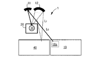
- 1 is a schematic plan view of a device according to the invention
- FIG. 1 is a plan view of essential parts of a device according to the invention
- FIG. 1 is a side view of the main part of the device according to the invention
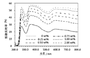
- FIG. 1 is a graph of absorbance versus wavelength according to one embodiment of the present invention
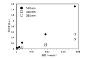
- 4 is a graph of absorbance versus solution concentration at each wavelength according to one embodiment of the present invention
- 4 is a graph of absorbance versus wavelength according to a comparative example
- It is a graph of absorbance versus solution concentration at each wavelength according to a comparative example.
- 1 is a graph of (a) absorbance vs.
- 1 is a graph of (a) absorbance versus solution concentration at each wavelength according to one embodiment of the present invention, and (b) an enlarged vertical axis thereof.
- 1 is a graph showing (a) absorbance versus wavelength and (b) an enlarged vertical axis at each concentration of a diffuse reflector according to one embodiment of the present invention.
- 1 is a graph of (a) absorbance versus amount of diffuse reflector at each wavelength according to one embodiment of the present invention, and (b) an enlarged vertical axis thereof.
- 4 is a graph of light absorption spectra for various amounts of diffuse reflector according to one embodiment of the present invention
- 1 is a structural formula of a catalyst used in one embodiment of the present invention
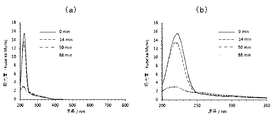
- 1 is a graph of (a) absorbance versus wavelength and (b) an enlarged horizontal axis thereof at each measurement time according to one embodiment of the present invention
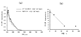
- 2 is a graph of (a) absorbance versus wavelength at various concentrations of iridium complexes, and (b) absorbance versus concentration of iridium complexes at various wavelengths, according to one embodiment of the present invention.
- 1 is a graph of (a) absorbance versus wavelength and (b) absorbance versus measurement time according to one embodiment of the present invention.
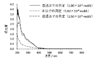
- 4 is a graph of absorbance versus wavelength.
- the solution S is rotated in a rotary stirring vessel 100.
- Rotational stirring at high speed around the shaft is contemplated.
- diffuse reflector particles 112 having a density higher than that of the solvent are put in the solution S and suspended.
- low-density bubbles 110 gather around the rotation axis (central axis) C of the rotary stirring tank 100, while high-density diffuse reflector particles 112 are unevenly distributed along the outer wall 100a of the rotary stirring tank 100.
- the air bubbles 110 are spatially separated.
- the incident light (probe light) L0 is incident on the rotating stirring tank 100 through the transparent outer wall 100a, and the reflected light (diffuse reflected light) L1 scattered by the diffuse reflector particles 112 is collected.
- the measurement can be made without being affected by the air bubble 110 . If the concentration of the diffuse reflector particles 112 is high, the distance between the particles for light reflection is shortened. As a result, the light absorption by the solution existing between the particles is apparently weakened and reflected in the diffuse reflectance spectrum. This will be described later in Examples.
- the incident light L 0 can also measure the optical spectrum using light in a wide range of wavelengths, such as ultraviolet to visible to near infrared to infrared, making it possible to measure the optical spectrum of reactions and solutions that could not be measured before.
- Examples include water as the main solvent and hydrogen as the generated gas, but the combination is not limited to this combination.
- it can be applied to optical spectrum measurement in a system in which a gas (bubbles) mixed with a solution exists.
- the solvent is not limited to water, and inorganic, organic, and mixed solutions thereof can also be applied.
- FIG. 1B is a partially enlarged view of FIG. According to this, the light L 0 incident on the solution S, or the light reflected by or transmitted through a certain diffuse reflector particle 112, is reflected by or transmitted through another diffuse reflector particle 112. Repeat.
- the diffuse reflector particles 112 are made of a transparent material that does not absorb the incident light L0 or the like, the light transmitted through the particles 112 is not attenuated. In other words, the attenuation of light is due to the solution S present between the diffuse reflector particles 112 .
- the concentration of the diffuse reflector particles 112 increases, the average distance between the particles decreases, and the attenuation of light due to the light absorption of the solution S becomes difficult. be.
- the concentration of the diffuse reflector particles 112 is low, the light absorption intensity is apparently stronger.
- the concentration of the diffuse reflector particles 112 is too low, the frequency of diffuse reflection by the diffuse reflector particles 112 will decrease, and the effect of the air bubbles 110 will relatively increase.
- the incident light L0 may pass through the solution S and reach the opposite side of the rotating stirring vessel (cell). For this reason, it should be considered that the measurement accuracy of the wavelength dependence of the light absorption intensity may be lowered. This will be discussed later.
- FIG. 2 shows the concept of a measuring device that accommodates the above-described rotary stirring vessel 100 as a cell 30.
- the apparatus 1 comprises a light source section 10 including a light source 10a, reflecting mirrors 11 and 12, a sample chamber 20 containing a cell 30, and a spectroscopic section 40.
- Incident light ( The probe light) L 0 is directed to the cell 30 of the sample chamber 20 .
- the reflected light L1 from the cell 30 is led to the spectroscopic section 40 via the reflecting mirror 12 to perform spectroscopic analysis.
- FIG. 3 and 4 show a more detailed optical configuration around cell 30.
- FIG. Second reflecting mirrors 11 a and 12 a are inserted in the optical paths of the incident light L 0 and the reflected light L 1 , respectively, forming optical paths from the sample chamber 25 to the cell 30 and to the spectroscopic section 40 .
- the light source 10a of the light source unit 10 is selected according to the purpose of measurement, and is a light source that generates light of wavelengths in each region of ultraviolet, visible, near-infrared, and infrared light or in a region straddling these regions. is.
- the light source in addition to light sources such as halogen lamps, deuterium lamps, xenon lamps, and Globar lamps, monochromatic, high-luminance, and high-coherence light sources such as lasers can be selected according to the purpose.
- Light from the light source 10 a is collected by the reflecting mirror 11 and can be applied to the cell 30 .
- a lens, an optical fiber, or the like may be interposed therebetween.
- a sample made of a mixture of the solution S and the diffuse reflector particles 112 in the cell 30 emits a reflected light L1 along with the irradiation of the incident light L0 .
- the detection sensitivity can be enhanced by condensing the light with a condensing means such as the reflecting mirror 12 at a solid angle as large as possible.
- the diffusely reflected light L1 may be condensed by a lens, an optical fiber, or the like, as in the case of light irradiation.
- the condensed light is introduced into the spectroscopic section 40, and the light intensity corresponding to the wavelength is detected.
- the spectroscopic unit 40 can be selected according to its purpose, for example, a high-performance dual spectrometer with low stray light or a high-sensitivity two-dimensional detector in fluorescence/Raman scattering spectrum measurement.
- the sample (solution) S in the cell 30 is irradiated with the incident light L0 from the light source unit 10 , and the reflected light L1 is spectroscopically detected to detect the light intensity.
- a known measurement method may be used in which the cell 30 is irradiated with monochromatic light that has been dispersed, instead of irradiating the cell 30 with light to be dispersed.
- monochromatic light can be irradiated, and the spectroscopic unit 40 also has a spectroscopic function.
- modulated light that has passed through an interferometer typically a Michelson interferometer
- the concave reflecting mirror 12 is used here, barium sulfate or alumina is used instead of the reflecting mirror 12 for the purpose of condensing the diffusely reflected light L1 from the sample in the cell 30 and guiding it to the spectroscopic section 40 .
- the diffusely reflected light L1 may be condensed at a larger solid angle by using an integrating sphere coated with a white powder such as, for example, or coated with a metal such as aluminum or gold.
- the reflected light L 1 from the solution (sample) in the cell 30 may be mixed with the reflected light L 2 from the surface of the cell 30 (see FIG. 4 in particular). It is also required to prevent this and improve measurement accuracy.
- the diffusely reflected light is emitted at a solid angle of 2 ⁇ . Therefore, as long as the solution in the cell 30 can be irradiated with light, there is no condition on the angle of incidence. The same applies to the direction of the detected reflected light L1.
- the angular dependence of the intensity distribution of the reflected light L1 is maximized when the incident angle and the reflection angle match , as in the case of light reflection in a normal smooth-plane continuum material, It is preferable to collect the diffusely reflected light L1. At this time, since the reflection angle is close to the reflection angle of specularly reflected light from the surface of the cell 30, it is necessary to pay attention to mixing of the specularly reflected light, as described above.
- the sample chamber 20 is a chamber (space) in which the temperature and pressure of the cell 30 can be kept constant, and the sample chamber 20 and the cell 30 may be integrated. It can be appropriately selected according to the temperature and pressure conditions required for the process, the medium to be introduced into the cell 30, and the like.
- a cryostat or the like is used to control the temperature with liquid helium, liquid nitrogen, liquid oxygen, liquid carbon dioxide, etc., and each temperature of -269 ° C., -196 ° C., -183 ° C. or higher can be controlled in At this time, it is necessary that the solution to be measured does not solidify (freeze).
- a heat medium for example, Dowtherm A, silicone oil, water, or the like is used for temperature control, and the temperature can be controlled at each temperature of 257° C., 150° C., and 100° C. or less.
- the pressure can be controlled to a negative pressure of 10 ⁇ 5 Pa, 0.1 Pa, 10 Pa, 1.01325 ⁇ 10 5 Pa (normal pressure) or higher by a vacuum pump.
- the positive pressure of 1 MPa, 10 MPa, 100 MPa, 1 GPa, and 1 PPa (prissascal) can be controlled by a pressure pump.
- the inner wall of the sample chamber 20 can be selected to be a metal such as an aluminum material or a highly reflective material with a metallic luster.
- a metal such as an aluminum material or a highly reflective material with a metallic luster.
- the incident light L 0 introduced into the cell 30 is less likely to be scattered by the diffuse reflector particles 112 and may reach the inner surface of the sample chamber 20 containing the cell 30.
- aluminum can reflect this light back to the surface of the cell 30 that is irradiated with light to increase the intensity of the reflected light.
- the inner wall of the sample chamber 20 can also function as an integrating sphere.
- the amount of bubbles 110 generated is large, or when the size of the bubbles 110 is large, there is a possibility that the reflected light intensity fluctuates over time.
- the surface on which the incident light L0 is incident is preferably spherical, planar, or cylindrical. It can be selected according to the conditions required for measurement, such as a cylindrical shape. Furthermore, as described above, in the diffuse reflectance measurement, the reflected light L2 from the surface of the cell 30 does not travel on the same optical path as the target diffuse reflected light L1 from the solution S, and is not guided to the spectroscopic section 40. It is necessary to A cylindrical (columnar) cell having an axis of rotational symmetry is more suitable if this condition is satisfied and high-speed stirring is possible without sedimentation of the diffuse reflector particles 112 . In addition, since the spherical surface tends to spread the reflected light L2 and become the same optical path as the diffusely reflected light L1, it is necessary to sufficiently consider the optical path design such as the relative angle between the incident light L0 and the cell 30.
- the material of the cell 30 in the sample chamber 20 or the material of the optical window portion of the cell 30 irradiated with the incident light L0 is not particularly limited as long as it is transparent to the wavelength to be used. Any material that is used as a window member for the application and that is chemically stable against the solvent may be used.
- borosilicate glass for example, borosilicate glass, quartz glass, synthetic quartz glass, non-fluorescent quartz glass, black quartz glass, infrared synthetic quartz glass, chalcogenite glass, plastic (main components are polystyrene (PS), polymethyl methacrylate (PMMA) , polyacrylic acid (PAA), etc.), zinc sulfide (ZnS), zinc selenide (ZnSe), thallium bromoiodide (KRS-5), calcium fluoride (CaF 2 ), barium fluoride (BaF 2 ), bromine Potassium chloride (KBr), sapphire (Al 2 O 3 ), diamond (C), germanium (Ge), silicon (Si), or the like can be used as appropriate.
- PS polystyrene
- PMMA polymethyl methacrylate
- PAA polyacrylic acid
- ZnS zinc sulfide
- ZnSe zinc selenide
- KRS-5 thallium bromoiodide
- the solution (medium) S in the cell 30 varies depending on the reaction system, and the material of the diffuse reflector particles 112 is selected according to each solution. It is necessary that the reflector particles 112 themselves be made of a transparent powder material that does not absorb light. In addition, it is preferable that the material has a refractive index greatly different from the refractive index of the solution S because the diffusely reflected light from the diffuse reflector particles 112 is observed. Furthermore, a material that is chemically stable with respect to the solvent used and does not affect the reaction should be appropriately selected.
- various ceramics alumina, zirconia, silica, ceria, calcia, titania, hafnium oxide, magnesia, barium oxide, tungsten oxide, barium titanate, boron nitride, aluminum nitride, hydroxyapatite
- various salts lithium chloride, sodium chloride
- potassium chloride calcium chloride, magnesium chloride, barium chloride, lithium fluoride, sodium fluoride, potassium fluoride, calcium fluoride, magnesium fluoride, barium fluoride, magnesium sulfate, calcium sulfate, barium sulfate, magnesium carbonate, carbonate calcium, barium carbonate), diatomaceous earth, carbon, various glasses (quartz, soda lime glass, crystal glass, etc.), various plastics (polytetrafluoroethylene (PTFE), polystyrene (PS), polymethyl methacrylate (PMMA), polyacrylic Acid (PAA, etc.), polymer fine particles, or
- the particle size of the diffuse reflector particles 112 is required to be a size that effectively diffuses reflection in the wavelength range to be measured.
- the particle size is smaller than the wavelength, Mie scattering and Rayleigh scattering, not scattering due to specular reflection on the particle surface of the diffuse reflector particles 112, occur. Therefore, although it is appropriately selected according to the wavelength, it is preferable that the particle diameter size of the diffuse reflector particles 112 is approximately the same as or larger than the wavelength to be measured.
- it is too large it will be difficult to disperse it in the solution S by stirring, and it will settle. Also, multiple reflections and transmissions resulting in diffuse reflection may not be obtained within the finite size cell 30 .
- the intensity of the diffusely reflected light may become weak and may not be approximated as diffusely reflected light. Therefore, when the diffuse reflector particles 112 having a large particle size are used, the size of the depth direction of the cell 30 with respect to the incident light L0 and the spot size of the incident light L0 irradiated to the cell 30 are detected. Ingenuity is required, such as adjusting the range on the surface of the cell 30 of the diffusely reflected light L1. Typically, for example, when a wavelength of ultraviolet to visible light of 190 to 700 nm is used for measurement, the particle size of the diffuse reflector particles 112 may be about 1 ⁇ m.
- particles having a size or size range of 1 ⁇ m to 1000 ⁇ m which is the size of powders of various ceramics, may be used.
- the concentration of the diffuse reflector particles 112 put into the cell 30 the higher the concentration of the diffuse reflector particles 112 , the stronger the intensity of the diffusely reflected light L1, which improves the measurement sensitivity and reduces the influence of the air bubbles 110. can be reduced, but on the other hand, the amount of solution S is reduced, making it difficult to obtain the optical spectrum itself. Therefore, it is preferable to adjust the concentration appropriately according to the reaction conditions.
- the optimum concentration conditions can be selected and used in the reaction solution in the range of 0.001% by weight or more and 100% by weight or less.
- the solution S inside the cell 30 is rotationally stirred to generate centrifugal force, and the separation of the air bubbles 110 can be promoted, but the required number of rotations depends on the viscosity of the reaction solution and the amount of gas generated. Typically, it can be appropriately adjusted within the range of 1 to 10000 revolutions/minute.
- Rotational stirring of the solution S inside the cell 30 is provided by a rotating mechanism controlled by the controller, and the method is not particularly limited, but includes, for example, a stirrer 32 consisting of a magnetic stirrer and a stirring unit 33 .
- a stirrer 32 consisting of a magnetic stirrer and a stirring unit 33 .
- various methods such as a method using a mechanical stirrer and a method of rotating the cell 30 can be used.
- the diffuse reflector particles 112 in the cell 30 and the generated air bubbles 110 microscopically undergo dynamic changes as the solution S is stirred. This can give temporal intensity fluctuations to the diffusely reflected light L 1.
- the reflected light L 1 detected by the spectroscopic unit 40 is subjected to time smoothing processing, and the time constant is set to 0.1 to 1 second. If so, it was confirmed that there is no particular problem with the observation sensitivity of the examples described later. This is because the area on the surface of the cell 30 illuminated by the incident light L0 and the depth at which the incident light L0 penetrates into the cell 30 are sufficient, and the dynamic changes described above are spatially and temporally It is a situation that is generally averaged. Note that, as described above, when a finite number of large bubbles 110 exist within the spatial region that is the optical path of the incident light L0 , it may not be possible to regard dynamic changes that can be averaged.
- Example 1 (dye: measurement of alizarin solution) Diffuse reflector particles made of alumina powder were added to an aqueous solution of alizarin, which is known as a dye.
- alumina is insoluble in water and chemically stable in solutions (solvents).
- the aqueous solution in which the alumina particles are dispersed becomes cloudy. That is, it satisfies the requirements suitable for the diffuse reflector particles described above.
- a representative example using alumina is shown here, similar results are obtained with diffuse reflector particles made of an equivalent material.
- the suspension was stirred and suspended at a speed of 800 rpm at a height of 20 mm), and the reflected light spectrum was measured.
- the diffuse reflectance of 100% was obtained by placing only the ⁇ -alumina powder in the cylindrical cell described above.
- the diffuse reflectance of 0% was obtained by placing a shielding plate in the middle of the scattered light path to prevent scattered light from entering the detector of the spectrophotometer.
- a Cary 5000 UV-Vis spectrophotometer manufactured by Agilent Technologies, Inc. was used for spectroscopy.
- the irradiation area of the irradiation light was adjusted to about ⁇ 5 mm on the cell surface, and the size of the mirror was a concave mirror with a diameter of 100 mm.
- the measurement range was a wavelength range from 900 nm to 200 nm, and the scan speed was 100 nm/min.
- a transmissive measurement was performed by putting an aqueous solution of alizarin without adding a diffuse reflector into a square quartz cell.
- 2.27 mg of alizarin was dissolved in 25 mL of an aqueous sodium hydrogen carbonate solution (manufactured by Wako Pure Chemical Industries, Ltd.) and diluted to give 0.0378, 0.0189, 0.00378, 0.00189, and 0.000378 mmol/ Each solution of L was prepared.
- Each solution was stored in a quartz prismatic cell with a side length of 10 mm, the temperature was set to 18 ° C., and the transmitted light absorption spectrum was measured using a Cary 60 UV-Vis spectrophotometer manufactured by Agilent Technologies. I made a measurement.
- FIG. 5 shows the light absorption spectrum obtained by converting the measured diffuse reflectance spectrum using the Kubelka-Munk formula described above.
- FIG. 6 shows a graph showing the concentration dependency by setting the absorbance at each wavelength of 520 nm, 330 nm and 261 nm from these light absorption spectra on the vertical axis and the solution concentration on the horizontal axis.
- FIGS. 7 and 8 show graphs showing the light absorption spectrum and the concentration dependency measured in a general transmission cell.
- a result corresponding to the transmitted light absorption spectrum measured using a general transmissive cell in the comparative example was obtained.
- the signal intensity increased linearly with concentration, reflecting the measurement of the transmitted light absorption spectrum using a general transmission cell. That is, it can be seen that the method of the present invention can measure the light absorption spectrum in the same manner as in the conventional method.
- each solution was sequentially placed in a quartz cylindrical cell, the temperature was set to 18° C., and the mixture was stirred and suspended with a Teflon stirrer at a speed of 800 rpm.
- ⁇ Diffuse reflectance spectra were measured with a Cary 5000 UV-Vis spectrophotometer manufactured by Technology Co., Ltd.
- the measured diffuse reflectance spectrum is divided by the diffuse reflectance spectrum of alumina only, and the value is converted into absorbance (KM), which is a dimensionless quantity proportional to the absorption coefficient, according to the Kubelka-Munk equation described above. converted.
- FIG. 9 shows the light absorption spectrum obtained by converting the measured diffuse reflectance spectrum.
- FIG.9(b) expands the vertical axis
- the absorption peak appearing at 300 nm in the figure is due to nitrate ions (NO 3 ⁇ ), and the absorption at 500 nm is due to cobalt ions (Co 2+ ).
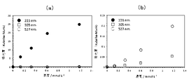
- FIG. 10 shows a graph plotting the concentration and absorbance of the cobalt nitrate solution at wavelengths of 221, 305 and 527 nm. From these, it can be seen that the signal intensity is proportional to the concentration.
- FIG. 10(a) it seems that there is a tendency to saturate at a certain light intensity (approximately 20 KM) or more, but this is due to the dynamic range of the spectroscope.
- Example 3 (Diffuse reflector concentration) An aqueous solution of cobalt (II) nitrate with varying amounts of a diffuse reflector consisting of ⁇ -alumina powder was placed in a quartz cylindrical cell, and the reflection spectrum was measured while stirring and suspending.
- Each solution was placed in a quartz cylindrical cell and measured in the same manner as described above. Divide the measured diffuse reflectance spectrum of the solution containing cobalt (II) nitrate by the diffuse reflectance spectrum measured only with the solution containing only alumina without adding cobalt (II) nitrate, and calculate the value according to the Kubelka-Munk equation. , the diffuse reflectance r was converted into absorbance (KM), which is a dimensionless quantity proportional to the absorption coefficient.
- FIG. 11 shows the light absorption spectrum after conversion.
- FIG. 11(b) is an enlarged view of the vertical axis indicating the light intensity in (a). Almost no diffusely reflected light was obtained with a solution containing no alumina as a diffusely reflecting material. Therefore, a spectrum with a low S/N ratio was obtained over the entire measurement area. In particular, a spectrum corresponding to nitrate ions could not be obtained in the wavelength region of 320 nm or less. On the other hand, when 0.25 wt % (50 mg of alumina/20 g of water) or more of the diffuse reflection material was applied, a diffuse reflection spectrum caused by cobalt (II) nitrate was obtained.
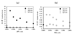
- FIG. 12 shows a graph plotting the concentration and absorbance of the cobalt nitrate solution at wavelengths of 221, 305, and 527 nm. As shown in FIG. 12(a) and FIG. 12(b) in which the vertical axis is enlarged, it can be seen that a solution containing 0.5 wt % or more of alumina as a diffuse reflector exhibits concentration dependence.
- the concentration of the cobalt nitrate solution remains unchanged, it is observed that the apparent absorbance (light absorption intensity) tends to gradually decrease as the concentration of ⁇ -alumina increases. As noted above, this is due to variations in the average distance between diffuse reflector particles.
- the light absorption by cobalt ions in the aqueous solution is not so strong in the first place, and when the concentration of alumina is 0.5 wt% or less, the contribution of the diffuse reflector particles is small, so the incident light does not reach the back surface of the solution cell. , the diffuse reflectance spectrum cannot be measured accurately, and the light absorption is considered to be rather weak. That is, there is a suitable concentration of diffuse reflector particles for accurate diffuse reflectance spectral measurements.
- Example 4 (Decomposition reaction of formic acid) Using a catalyst composed of an iridium complex shown in FIG. 14, a diffuse reflector composed of ⁇ -alumina powder was added to an aqueous solution of formic acid. A diffuse reflectance spectrum was measured while decomposing to obtain carbon dioxide and hydrogen.
- ⁇ -alumina powder manufactured by Kojundo Chemical Laboratory Co., Ltd.
- 20 mg of ⁇ -alumina powder is dispersed in 20 g of a 3.7 mol/L formic acid aqueous solution, and 5.68 mg of an iridium complex (see FIG. 14) is dissolved.
- FIG. 15 shows the converted light absorption spectrum.
- FIG.15(b) is the graph which expanded the horizontal axis of (a).
- FIG. 16(a) shows the light absorption spectrum at each concentration of the iridium complex as a catalyst
- FIG. 16(b) shows a graph plotting the absorbance at each wavelength of 240, 330, 299, and 259 nm. rice field. As can be seen, there is a proportional relationship between catalyst concentration and absorbance.
- FIG. 17(a) shows the light absorption spectrum of only the solution of the iridium complex, which is the catalyst, superimposed on the light absorption spectrum of the solution in which the formic acid is completely decomposed and no bubbles are generated. Furthermore, FIG. 17(b) shows the change in absorbance with time at a wavelength of 222 nm, which corresponds to the absorption of formic acid. From this, it can be seen that the state of decrease due to the decomposition of formic acid has a proportional relationship with the absorbance. In other words, it can be seen that the progress of formic acid decomposition by the catalyst can be observed by this method.
- FIG. 18 shows a comparison with measurement by the transmission method. Since the catalyst concentration is different (this method: 5.00 ⁇ 10 -4 mol / L, transmission method: 1.00 ⁇ 10 -4 mol / L and 2.50 ⁇ 10 -4 mol / L), the optical spectrum Although the absorption intensities are different, the shapes of the spectrum diagrams are almost the same, indicating that this method can be measured in the same way as the transmission method.
Landscapes
- Physics & Mathematics (AREA)
- Spectroscopy & Molecular Physics (AREA)
- Health & Medical Sciences (AREA)
- Life Sciences & Earth Sciences (AREA)
- Chemical & Material Sciences (AREA)
- Analytical Chemistry (AREA)
- Biochemistry (AREA)
- General Health & Medical Sciences (AREA)
- General Physics & Mathematics (AREA)
- Immunology (AREA)
- Pathology (AREA)
- Engineering & Computer Science (AREA)
- Mathematical Physics (AREA)
- Theoretical Computer Science (AREA)
- Investigating Or Analysing Materials By Optical Means (AREA)
Abstract
気泡を含む溶液であっても該気泡の発生や成長の影響を受けることなく、高感度、高精度且つ安定した光学スペクトルの測定を行うことの可能な測定方法及びその装置を提供する。装置は拡散反射材粒子を加えられた溶液をセルに与えて該溶液の光学スペクトルを測定するものである。セルの光学窓に沿って拡散反射材粒子の分散流れを形成させるように回転軸の周りで回転攪拌させる回転機構と、光学窓を介して入射光を与え且つ拡散反射材粒子で散乱してくる拡散反射光を得てその光学スペクトルを測定する光学系と、を含む。かかる装置において、溶液に拡散反射材粒子を加え、セルの光学窓に沿って拡散反射材粒子の分散流れを形成させるように回転軸の周りで回転攪拌させる。この光学窓を介して入射光を与え且つ拡散反射材粒子で散乱してくる拡散反射光を得てその光学スペクトルを測定する。
Description
本発明は、溶液の光学スペクトルの測定方法及びその測定装置に関し、特に、気泡を含む溶液の光学スペクトルの測定方法及びその測定装置に関する。
ギ酸(HCOOH)を適当な触媒下で分解すると、一酸化炭素(CO)をほとんど発生させずに、選択的に水素(H2)及び二酸化炭素(CO2)を得ることができる。例えば、特許文献1では、金属錯体からなる液体触媒を用い、反応を耐圧容器中で行うことで高圧の水素と二酸化炭素を得る方法を開示している。ここで、反応溶液中に溶解させた金属錯体触媒の劣化状態などをin-situ(その場)観察するには、溶液の光学スペクトルを測定することが提案される。一方、かかる反応系の溶液では、生成する気泡(ガス泡)による光の散乱及び/又は反射があるため、透過型又は反射型のいずれの光吸収スペクトルの測定方法であっても、受光系において十分かつ安定した光強度を得られず、信号対ノイズ比(S/N比)の低い信号となって、正確な測定をすることが難しい、微量な変化の検出が難しいといった問題がある。
ここで、光吸収スペクトルの測定におけるS/N比を高める方法が数多く提案されている。例えば、特許文献2では、積分球を使って集光し光吸収強度を上げて光吸収スペクトルを測定する方法が開示されている。また、非特許文献1では、一般的に、粉体や固体試料の測定を対象とする拡散反射法において、液体である油脂を粉体の表面に含浸させて乾燥させ、その表面を鏡面加工した上で拡散反射法により油脂からの反射光強度を高めて光吸収スペクトルを測定する方法について述べている。
藤沢健、「溶液試料滴下拡散反射法による鉱油系潤滑油の定量分析」、長野県工業技術総合センター研究報告、No.14,p.M1~M6,2019年
上記したように、ギ酸の分解反応のようにガスを発生させる反応系では、溶液中に含まれる気泡によって該溶液の正確な光吸収スペクトルの測定が難しくなる。また、気泡(ガス泡)は反応容器の内表面から発生し、その場に付着して成長し、そして最終的には脱離していく。即ち、時間的且つ空間的に気泡の体積や密度、そして分布状態が変化する。そのため、受光系の光感度を高めたとしても、波長掃引型の測定や、経時変化を追跡する繰り返し(インターバル)測定のような、一定の時間を要する測定においては、時間的且つ空間的な気泡の変化が測定データに反映され安定かつ正確な測定が難しい。
本発明は、上記したような事情を鑑みてなされたものであって、その目的とするところは、溶液の光学スペクトルの測定方法及びその測定装置において、新規な手法を提案するもので、気泡を含む溶液であっても該気泡の発生や成長の影響を受けることなく、高感度、高精度且つ安定した光学スペクトルの測定を行うことの可能な測定方法及びその装置を提供することにある。
本願発明者らは、一般的には粉体や固体試料の分光分析法である拡散反射法の概念と測定方法を根本から考え直し、かつ、鋭意研究した結果、液体試料、特に、ガスを発生させる反応系の溶液であっても、時間的且つ空間的に検出信号を安定化させ、しかも、信号強度を高めることのできる測定方法と装置を提供できることを見いだした。
詳細には、従来の拡散反射法による光学スペクトルの測定では、一般的に被測定物は粉体であるが、この粉体が色を有しておりそのため光を吸収し、且つ、個々の粒子が光散乱の担い手として機能する。この際、粒子間には空気などの無色透明なガス(気体)、もしくは脱気による真空状態が介在する。ここで、本願発明では、前記した従来の拡散反射法の概念とは逆に、被測定物である溶液自身が色を有する、つまり、光吸収を有し、溶液内に無色透明な粉体粒子を分散させることで光を拡散又は反射させるという基本着想に想到した。すなわち、従来の拡散反射法と比較すると、ポジとネガの関係とも言える。かかる着想を基軸に、後述する回転撹拌法を組み合わせて、本発明を完成させるに至った。
すなわち、本発明による方法は、セルに与えられた溶液の光学スペクトルの測定方法であって、前記溶液に拡散反射材粒子を加え、前記セルの光学窓に沿って前記拡散反射材粒子の分散流れを形成させるように回転軸の周りで回転攪拌させるとともに、前記光学窓を介して入射光を与え且つ前記拡散反射材粒子で散乱してくる拡散反射光を得てその光学スペクトルを測定することを特徴とする。
かかる特徴によれば、光学窓近傍の溶液で測定を行って、それ以外の溶液部分の状態に影響を受けず、高感度、高精度且つ安定した光学スペクトルの測定を行うことができるのである。従来、分光分析を出来なかった高濃度溶液、懸濁液においても測定が可能であって、しかも、紫外~可視~近赤外~赤外といった幅広い波長範囲の光学スペクトルの測定が可能である。
上記した発明において、前記拡散反射材粒子で散乱してくる前記拡散反射光を集光する集光手段を含むことを特徴としてもよい。かかる特徴によれば、反射光強度を高めることができて、高感度且つ高精度で光学スペクトルの測定を行うことができるのである。
上記した発明において、前記溶液は気泡を含み、前記回転攪拌による遠心力により前記気泡を前記回転軸の周囲に偏在させることを特徴としてもよい。また、前記気泡は前記溶液の反応により生じることを特徴としてもよい。かかる特徴によれば、気泡を含む溶液であっても該気泡の発生や成長の影響を受けることなく、高感度且つ高精度で光学スペクトルの測定を行うことができるのである。
また、本発明による装置は、拡散反射材粒子を加えられた溶液をセルに与えて該溶液の光学スペクトルを測定する装置であって、前記セルの光学窓に沿って前記拡散反射材粒子の分散流れを形成させるように回転軸の周りで回転攪拌させる回転機構と、前記光学窓を介して入射光を与え且つ前記拡散反射材粒子で散乱してくる拡散反射光を得てその光学スペクトルを測定する光学系と、を含むことを特徴とする。
かかる特徴によれば、光学窓近傍の溶液で測定を行うことができて、それ以外の溶液部分の状態に影響を受けず、高感度、高精度且つ安定した光学スペクトルの測定を行うことができるようになるのである。従来、分光分析を出来なかった高濃度溶液、懸濁液においても測定が可能となり、しかも、紫外~可視~近赤外~赤外といった幅広い波長範囲の光学スペクトルの測定が可能である。
上記した発明おいて、前記拡散反射材粒子で散乱してくる前記拡散反射光を集光する集光手段を含むことを特徴としてもよい。かかる特徴によれば、反射光強度を高めることができて、高感度、高精度且つ安定した光学スペクトルの測定を行うことができるのである。
上記した発明において、前記溶液は気泡を含み、前記回転攪拌による遠心力により前記気泡を前記回転軸の周囲に偏在させるように回転機構を制御する制御部を含むことを特徴としてもよい。かかる特徴によれば、気泡を含む溶液であっても該気泡の発生や成長の影響を受けることなく、高感度、高精度且つ安定した光学スペクトルの測定を行うことができるのである。
図1(a)に示すように、ギ酸の分解反応のようなガスを発生させる反応系の溶液Sにおいて、気泡110を均一に分散させるためには、回転攪拌槽100の中で溶液Sを回転軸の周囲に高速で回転攪拌させることが考慮される。ここで、溶液S中には、溶媒よりも密度の高い拡散反射材粒子112を入れて懸濁させておく。すると、遠心力により、密度の低い気泡110が回転攪拌槽100の回転軸(中心軸)Cの周囲に集まる一方、密度の高い拡散反射材粒子112が回転攪拌槽100の外壁100aに沿って偏在し分散流れを形成するとともに、気泡110が空間的に分離される。かかる状態で、入射光(プローブ光)L0を透明な外壁100aを介して回転攪拌槽100に入射させ、拡散反射材粒子112によって散乱される反射光(拡散反射光)L1を集光し光学スペクトルを測定することで、気泡110の影響を受けずにその測定が可能となるのである。なお、拡散反射材粒子112の濃度が高ければ、光反射をさせる粒子間距離を短くさせる結果、粒子間に存在する溶液による光吸収が見かけ上弱まって拡散反射スペクトルに反映されることになる。これについては、実施例にて後述する。
上記した方法では、反応時にガス発生し気泡110を生じる、生じないに関わらず、従来、光学スペクトルの測定が出来なかった高濃度の溶液、懸濁液などでも測定が可能である。入射光L0も、紫外~可視~近赤外~赤外など、幅広い波長範囲の光を用いて光学スペクトルの測定をでき、これまで測定できなかった反応や溶液の光学スペクトルの測定が可能となる。また、主溶媒として水を、発生ガスとして水素を、一例として挙げられるが、この組み合わせに限定されるものではなく、酵素反応や炭酸水からの二酸化炭素の発生を始め、メタン、硫化水素、酸素など、溶液と混合状態となるガス(気泡)が存在する系での光学スペクトルの測定に適用可能である。また、溶媒も水に限らず、無機、有機、及びそれらの混合溶液等についても適用できる。
図1(b)は、図1(a)を部分的に拡大したもので、拡散反射材粒子112による光の拡散について模式的に示したものである。これによれば、溶液Sへの入射光L0、または、ある拡散反射材粒子112によって反射又はこれを透過した光は、更に、他の拡散反射材粒子112にて反射又はこれを透過することを繰り返していく。ここで、拡散反射材粒子112は、入射光L0などに対して光吸収を生じない透明な材質であるから、該粒子112を透過する光は減衰しない。つまり、光の減衰は、拡散反射材粒子112の粒子間に存在する溶液Sによるものとなるのである。
そのため、拡散反射材粒子112の濃度が高くなると、平均粒子間距離が小さくなり、溶液Sの光吸収による光の減衰は生じにくくなり、見かけ上、得られるスペクトルの光吸収強度は弱めに観察される。一方、拡散反射材粒子112の濃度が低くなると、見かけ上、光吸収強度は強めに観察される。これらのことから、拡散反射材粒子112の濃度を低くし過ぎると、該拡散反射材粒子112による拡散反射の頻度が下がり、気泡110の影響を相対的に増大させることになる。また、溶液Sを入射光L0が通過し回転攪拌槽(セル)の反対側に到達してしまうことも生じうる。このため、光吸収強度の波長依存性における測定精度が低下する恐れを考慮すべきである。これについては後述する。
図2には、上記した回転攪拌槽100をセル30として収容する測定装置の概念を示した。装置1は、光源10aを含む光源部10、反射鏡11及び12、セル30を収容するサンプル室20、分光部40から構成され、光源部10の光源10aから反射鏡11を介して入射光(プローブ光)L0をサンプル室20のセル30に導く。また、セル30からの反射光L1について反射鏡12を介して分光部40へと導いて分光分析を行うものである。
図3及び4には、セル30の周囲のより詳細な光学系の構成を示した。入射光L0及び反射光L1のそれぞれの光路中には第2の反射鏡11a及び12aを挿入され、試料室25からセル30へ、また、分光部40へと光路を形成している。
ここで、光源部10の光源10aについては、測定目的に合わせて選択され、紫外~可視~近赤外~赤外光の各領域又はこれらに跨がった領域の波長の光を発生させる光源である。光源としては、ハロゲンランプ、重水素ランプ、キセノンランプ、グローバーランプ等の光源のほか、レーザーなどの単色、高輝度、高コヒーレンスな光源など、目的に応じて選択可能である。
光源10aからの光は、反射鏡11によって集光され、セル30に照射可能である。必要に応じて、反射鏡11に代わり、レンズ、光ファイバ等を間に介していても良い。セル30内の溶液Sと拡散反射材粒子112の混合物からなる試料からは、入射光L0の照射に伴い、反射光L1が発せられる。これを反射鏡12のような集光手段によって可能な限り大きな立体角にて集光することにより、検出感度を高めることができる。なお、光照射時と同様に、レンズや光ファイバ等により拡散反射光L1を集光してもよい。集光された光は分光部40に導入され、波長に対応した光強度を検出される。分光部40はその目的に応じて、例えば、蛍光・ラマン散乱スペクトル測定では低迷光の高性能二重分光器や高感度な二次元検出器等、目的に応じて選択され得る。
なお、光源部10からの入射光L0をセル30内の試料(溶液)Sに照射し、その反射光L1を分光して光強度を検出するが、例えば、光吸収スペクトル測定では、白色光をセル30に照射して分光するのではなく、分光された単色光をセル30に照射する公知の測定方法であってもよい。また、蛍光測定でも単色光の照射ができるが、分光部40においても分光機能を与えることになる。更に、赤外光の領域での光吸収スペクトルでは、干渉計(典型的には、マイケルソン干渉計)を通過した変調光を入射光L0として用いてもよい。
ここでは、凹面型の反射鏡12を用いているが、セル30内の試料からの拡散反射光L1を集光し、分光部40に導く目的において、反射鏡12に代わり、硫酸バリウムやアルミナ等の白色粉末体を塗布した、または,アルミニウム、金などの金属をコーティングした積分球を用いて、更に大きな立体角にて拡散反射光L1を集光しても構わない。ただし、溶液(試料)の光吸収が強い場合、セル30内の溶液(試料)からの反射光L1に、セル30の表面からの反射光L2(特に、図4参照)が混入することを防止し、測定精度を向上させることも求められる。
一般に平坦な固体粉末に光照射させる場合には、拡散反射光は立体角2πで放射される。故に、セル30内の溶液に光照射が可能である限り、入射角には条件はない。また、検出される反射光L1の方向についても同様である。ただし、反射光L1の強度分布の角度依存性は、通常の平滑平面の連続体物質における光反射のように、入射角と反射角とが一致した場合に最大となるため、その角度近傍の拡散反射光L1を集光することが好ましい。このとき、セル30の表面からの正反射光の反射角に近いため、前記した通り、正反射光の混入に注意を払う必要がある。
サンプル室20は、セル30の温度と圧力を一定に保持することができる部屋(空間)であり、サンプル室20とセル30が一体となっていても良く、その温度と圧力の範囲は、測定に必要な温度や圧力条件、セル30に導入する媒体などに応じて適宜、選択できる。
例えば、セル30の温度を冷却するのに、クライオスタットなどを用いて液体ヘリウム、液体窒素、液体酸素、液体二酸化炭素などで温度制御し、-269℃、-196℃、-183℃以上の各温度において制御可能である。この際、測定対象である溶液が固化(凍結)しないことが必要である。また熱媒として、例えば、ダウサムAやシリコーン油、水などで温度制御し、257℃、150℃、100℃以下の各温度において制御可能である。
また、圧力も真空ポンプによって、10-5Pa、0.1Pa、10Pa、1.01325×10⁵Pa(常圧)以上の負圧に制御できる。更に、加圧ポンプによって、1MPa、10MPa、100MPa、1GPa、1PPa(ペタパスカル)の正圧にも制御できる。
サンプル室20の内壁は、アルミニウム素材などの金属あるいは金属光沢をもつ高反射率材料であることを選択できる。例えば、拡散反射材粒子112の密度が低い場合、セル30に導入された入射光L0は拡散反射材粒子112で散乱されにくく、セル30を入れたサンプル室20の内表面に到達する可能性がある。近赤外~可視~紫外光領域の場合、アルミニウムによりこの光を反射させ、光照射されるセル30の表面に戻せば、反射光強度を高めることができる。換言すれば、サンプル室20の内壁を積分球として機能を併せ持つようにできる。但し、気泡110の発生量が多い場合や、気泡110のサイズが大きい場合、反射光強度が時間的に揺らぐ恐れがある。
サンプル室20の中にあるセル30の形は、少なくとも、入射光L0の入射する面を球面、平面、柱面のいずれかの形状にすることが好ましく、球形、四角柱形、三角柱形、円筒形など、測定に必要な条件に応じて選択できる。更に、上記したように、拡散反射測定では、セル30の表面からの反射光L2が目的とする溶液Sからの拡散反射光L1と同一光路上に乗らず、分光部40に導かれないようにする必要がある。この条件を満たした上で、拡散反射材粒子112が沈降しない高速な撹拌を可能とする場合には、回転対称軸を有する円筒状(円柱状)のセルがより好適となる。なお、球面は反射光L2が広がりやすく、拡散反射光L1と同一光路となりやすいため、入射光L0とセル30の相対角などの光路設計を十分に考慮する必要がある。
サンプル室20の中にあるセル30、あるいはセル30の入射光L0の照射される光学窓部の材質は、使用する波長に対して透明であればよく、特に限定されないが、一般的に分光用窓部材として使用されているもの、そして溶媒に対して化学的に安定であればよい。例えば、ホウケイ酸ガラス、石英ガラス、合成石英ガラス、無蛍光石英ガラス、ブラック石英ガラス、赤外用合成石英ガラス、カルコゲナイトガラス、プラスチック(主成分がポリスチレン(PS)、ポリメタクリル酸メチル(PMMA)、ポリアクリル酸(PAA)など)、硫化亜鉛(ZnS)、セレン化亜鉛(ZnSe)、臭沃化タリウム(KRS-5)、フッ化カルシウム(CaF2)、フッ化バリウム(BaF2)、臭化カリウム(KBr)、サファイヤ(Al2O3)、ダイヤモンド(C)、ゲルマニウム(Ge)、シリコン(Si)などを適宜用いることができる。
セル30の中の溶液(媒体)Sは、反応系に応じては様々であり、それぞれの溶液に対応して拡散反射材粒子112の材質を選択するが、測定する波長範囲に対して、拡散反射材粒子112自身が光吸収しない透明粉末材料からなることが必要である。また、拡散反射材粒子112による拡散反射光を観測することから、溶液Sの屈折率と大きく異なる屈折率を有する材料であることが好ましい。更に、用いる溶媒に対して化学的に安定で、反応に影響を与えない材質を適宜選択すべきである。例えば、各種セラミックス(アルミナ、ジルコニア、シリカ、セリア、カルシア、チタニア、酸化ハフニウム、マグネシア、酸化バリウム、酸化タングステン、チタン酸バリウム、窒化ホウ素、窒化アルミニウム、ハイドロキシアパタイト)、各種塩(塩化リチウム、塩化ナトリウム、塩化カリウム、塩化カルシウム、塩化マグネシウム、塩化バリウム、フッ化リチウム、フッ化ナトリウム、フッ化カリウム、フッ化カルシウム、フッ化マグネシウム、フッ化バリウム、硫酸マグネシウム、硫酸カルシウム、硫酸バリウム、炭酸マグネシウム、炭酸カルシウム、炭酸バリウム)、珪藻土、カーボン、各種ガラス(石英、ソーダ石灰ガラス、クリスタルガラスなど)、各種プラスチック(ポリテトラフルオロエチレン(PTFE)、ポリスチレン(PS)、ポリメタクリル酸メチル(PMMA)、ポリアクリル酸(PAA)など)、ポリマ微粒子など、あるいはこれらの複合材料などを用いることができる。更に、これらの素材からなる拡散反射材粒子112と、他の機能性粒子を適宜組み合わせて溶液Sに分散させて用いてもよい。
拡散反射材粒子112の粒径サイズは、測定する波長範囲において効果的に拡散反射する大きさであることが求められる。粒径サイズが波長よりも小さくなると、拡散反射材粒子112の粒子表面での鏡面反射による散乱では無く、ミー散乱やレイリー散乱の影響が生じる。そのため、波長に応じて適宜選択されるが、拡散反射材粒子112の粒径サイズは測定する波長と同程度か、それよりも大きいものが好適である。一方、大きすぎると、撹拌による溶液Sへの分散が困難となり沈降してしまう。また、拡散反射を生じる多重反射と透過が有限サイズのセル30内で得られない場合もある。この場合、拡散反射光の強度が弱くなって、拡散反射としても近似できない場合も生じ得る。このため、粒径サイズの大きな拡散反射材粒子112を用いる場合、入射光L0に対してセル30の深さ方向のサイズ、セル30に照射される入射光L0のスポットサイズ、検出される拡散反射光L1のセル30の表面での範囲を調整するなど、工夫を必要とする。典型的には、例えば、測定に紫外~可視光の190~700nmの波長を用いる場合、拡散反射材粒子112の粒径サイズは、1μm程度であればよい。また、近赤外~赤外線の波長を用いる場合には、700nm~約1000μm(1mm)程度であればよい。そのため、通常、各種セラミックス等の粉体のサイズである1μm~1000μmのいずれかのサイズあるいはサイズ幅をもった粒子であればよい。
セル30の中に入れる拡散反射材粒子112の濃度については、拡散反射材粒子112の濃度が高くなると、拡散反射光L1の強度が強くなり、測定感度を向上させ、且つ、気泡110の影響を低減できるが、一方で、溶液Sの量が減じられて光学スペクトル自体を得にくくさせる。そのため、反応条件に応じて適宜濃度を調整して用いることが好ましい。典型的には、反応溶液に0.001重量%以上100重量%以下の範囲で最適な濃度条件を選択して用いることができる。
セル30の内部の溶液Sを回転攪拌させて遠心力を発生させ、気泡110の分離を促進させ得るが、必要な回転数は、反応溶液の粘度やガス発生量に依存する。典型的には、1~10000回転/分の範囲の範囲で適宜調整することができる。
セル30の内部の溶液Sの回転攪拌は、制御部で制御される回転機構で与えられ、特にその方法は限定されないが、例えば、マグネットスターラからなる攪拌子32及び攪拌ユニット33を含む。もしくは、メカニカルスターラを用いる方法、セル30を回転させる方法など、各種方法を用い得る。
セル30の内部の溶液Sを回転攪拌することで、セル30の内壁に気泡110が付着することを抑制できる。また、撹拌により、溶液Sを機械的に刺激するため、静置状態では気泡110の発生しやすいセル30の内壁に限らず、気泡110が溶液Sの全体で生じる。このことは、気泡110が成長することを抑制し、成長した大きな気泡110が測定に影響を与えることを抑制する。つまり、小さな気泡110が多数発生するが、回転撹拌によりセル30内部の回転中心に集まることとなり、仮に、拡散反射材粒子112と同程度のサイズかそれ以下の気泡110は、拡散反射材粒子112に混在しこれと同様の働きを与えることにもなり得る。
セル30内の拡散反射材粒子112や発生する気泡110は、溶液Sの撹拌に伴って、微視的には動的変化を起こす。これは拡散反射光L1の時間的な強度揺らぎを与えることになり得るが、ここでは、分光部40における検出された反射光L1を時間平滑化処理しその時定数を0.1~1秒とすれば、後述する実施例の観測感度では、特に問題とならないことが確認された。これは、入射光L0の照射されるセル30の表面での面積、及び、入射光L0がセル30内に侵入する深さが充分にあって、前記した動的変化が空間的且つ時間的に平均化されている状況である。なお、上記したように、有限個の大きな気泡110が入射光L0の光路である空間領域内に存在する場合に、平均化可能な動的変化とは見なせないこともあり得る。
実施例1:(色素:アリザリン溶液の測定)
染料として知られるアリザリンの水溶液に、アルミナの粉体からなる拡散反射材粒子を加えた上で、石英製円筒形セルに入れ、攪拌、懸濁させながら拡散反射スペクトルの測定を行った。ここで、アルミナは水に対して不溶で溶液(溶媒)に対して化学的に安定であり、且つ、アルミナと水の屈折率はそれぞれ1.77及び1.33であって大きな屈折率差を有し、アルミナ粒子を分散させた水溶液は白濁状態となる。すなわち、上記した拡散反射材粒子に好適な要求を満たすものである。なお、ここでは、アルミナを用いた代表例を示したが、同等の材料からなる拡散反射材粒子でも同様の結果が得られている。
染料として知られるアリザリンの水溶液に、アルミナの粉体からなる拡散反射材粒子を加えた上で、石英製円筒形セルに入れ、攪拌、懸濁させながら拡散反射スペクトルの測定を行った。ここで、アルミナは水に対して不溶で溶液(溶媒)に対して化学的に安定であり、且つ、アルミナと水の屈折率はそれぞれ1.77及び1.33であって大きな屈折率差を有し、アルミナ粒子を分散させた水溶液は白濁状態となる。すなわち、上記した拡散反射材粒子に好適な要求を満たすものである。なお、ここでは、アルミナを用いた代表例を示したが、同等の材料からなる拡散反射材粒子でも同様の結果が得られている。
詳細には、アリザリン2.56mgを25mLの炭酸水素ナトリウム水溶液(和光純薬株式会社製)に溶解させた上で、それぞれ0.249、0.189、0.122、0.0387、0.0104mmol/Lの各溶液に調製した。各溶液には、拡散反射材として200mgのα-アルミナの粉体(粒子サイズ:平均粒子径約1μm、株式会社高純度化学研究所製)を加えた。これを順次、外径φ25mm、内径φ23.5mm、長さ200mmの石英製円筒形セルに収容し、温度を18℃に設定した上で、テフロン(登録商標)製攪拌子(円柱形φ5mm×長さ20mm)で800回転/分の速度で攪拌、懸濁させて反射光スペクトルの測定を行った。なお、100%の拡散反射率については、α-アルミナ粉体のみを前記した円筒形セルに入れて測定を行って得た。また、0%の拡散反射率については、散乱光路の途中に遮蔽板を配置し、分光光度計の検出器に散乱光が入らないようにして測定を行って得た。測定された拡散反射スペクトルを、アリザリンなしの炭酸水素ナトリウム水溶液のみの拡散反射スペクトルで除し、その値をKubelka-Munk式(KM=(1-r)2/2r)に従って、拡散反射率rを吸収係数に比例する無次元量である吸光度(KM:Kubelka-Munk)に変換処理した。
分光には、アジレント・テクノロジー株式会社製Cary 5000 UV-Vis分光光度計を用いた。照射光の照射面積はセル表面にて約φ5mmに調整し、ミラ-のサイズは直径100mmの凹面鏡である。測定範囲は900nmから200nmの波長範囲であり、スキャンスピードを100nm/minとした。
一方、比較例として、拡散反射材を加えないアリザリンの水溶液を石英製角形セルに入れて透過型の測定を行った。上記同様に、アリザリン2.27mgを25mLの炭酸水素ナトリウム水溶液(和光純薬株式会社製)に溶解させ希釈し、それぞれ0.0378、0.0189、0.00378、0.00189、0.000378mmol/Lの各溶液を調製した。各溶液は、一辺の長さ10mmの石英製角形セルに収容し、温度を18℃に設定した上で、アジレント・テクノロジー株式会社製Cary 60 UV-Vis分光光度計を用いて透過光吸収スペクトルの測定を行った。
図5には、測定された拡散反射スペクトルから前記したKubelka-Munkの式にて変換処理し得られた光吸収スペクトルを示した。また、図6には、これら光吸収スペクトルから520nm、330nm、261nmの各波長における吸光度を縦軸に、溶液濃度を横軸に設定して、濃度依存性を表すグラフを示した。更に、比較例として、図7及び8には、一般的な透過型セルにて測定された光吸収スペクトル、濃度依存性を表すグラフを示した。これらから分かるように、実施例においても、比較例の一般的な透過型セルを用いて測定された透過光吸収スペクトルと対応した結果を得られた。また、濃度による信号強度も同様に直線的に増加し、一般的な透過型セルを用いた透過光吸収スペクトルの測定を反映していた。つまり、本発明の方法により、従来と同様の光吸収スペクトルの測定を行い得ることが分かる。
実施例2:(基質濃度依存性)
実施例1と同様に、硝酸コバルト(II)水溶液に、α-アルミナの粉体からなる拡散反射材を加えた上で、石英製円筒形セルに入れ、攪拌、懸濁させながら反射光スペクトルの測定を行った。
実施例1と同様に、硝酸コバルト(II)水溶液に、α-アルミナの粉体からなる拡散反射材を加えた上で、石英製円筒形セルに入れ、攪拌、懸濁させながら反射光スペクトルの測定を行った。
20.039gの水に拡散反射材として200mgのα-アルミナの粉体(株式会社高純度化学研究所製)を分散させた。そして、硝酸コバルト(II)6水和物(和光純薬株式会社製)を各37.77、56.43、83.47、165.16mg加えた溶液を調製した。実施例1と同様に、各溶液を順次、石英製円筒形セルに収容し、温度を18℃に設定した上で、テフロン製攪拌子で800回転/分の速度で攪拌、懸濁させてアジレント・テクノロジー株式会社製Cary 5000 UV-Vis分光光度計で拡散反射スペクトルの測定を行った。測定された拡散反射スペクトルは、アルミナのみの拡散反射スペクトルで除し、その値を上記したKubelka-Munkの式に従って、拡散反射率rを吸収係数に比例する無次元量である吸光度(KM)に変換処理した。
図9には、測定された拡散反射スペクトルから変換処理を施した光吸収スペクトルを示した。なお、図9(b)は(a)における吸光度を示す縦軸を拡大したものである。なお、図の300nmに現れる吸収ピークは硝酸イオン(NO3
-)、500nmの吸収はコバルトイオン(Co2+)によるものである。また、図10には、波長221、305、527nmにおける硝酸コバルト溶液の濃度と吸光度をプロットしたグラフを示した。これらから、濃度に対して信号強度が比例関係にあることが分かる。なお、図10(a)では、一定の光強度(約20KM)以上で飽和する傾向にあるようにも見えるが、これは分光器のダイナミックレンジによるものである。
実施例3:(拡散反射材濃度)
硝酸コバルト(II)水溶液に、α-アルミナの粉体からなる拡散反射材の量を変化させて、石英製円筒形セルに入れ、攪拌、懸濁させながら反射スペクトルの測定を行った。
硝酸コバルト(II)水溶液に、α-アルミナの粉体からなる拡散反射材の量を変化させて、石英製円筒形セルに入れ、攪拌、懸濁させながら反射スペクトルの測定を行った。
硝酸コバルト(II)6水和物(和光純薬株式会社製)164.59ミリグラムを20.029gの水に溶解させた上で、拡散反射材としてα-アルミナの粉体(株式会社高純度化学研究所製)を、それぞれ51、102、153、203、303、403mg加えた溶液(α-アルミナの量比で、それぞれ、0.25、0.50、0.75、1.00、2.00wt%に対応)を作成した。また、α-アルミナの粉体を加えず、硝酸コバルト(II)のみの溶液も作成した。各溶液は、上記同様、石英製円筒形セルに入れて測定を行った。測定された硝酸コバルト(II)を含む溶液の拡散反射スペクトルを、アルミナのみの硝酸コバルト(II)を加えていない溶液のみで測定した拡散反射スペクトルで除し、その値をKubelka-Munkの式に従って、拡散反射率rを吸収係数に比例する無次元量である吸光度(KM)に変換処理した。
図11には、変換処理した光吸収スペクトルを示した。図11(b)は(a)における光強度を示す縦軸を拡大したものである。拡散反射材としてのアルミナを入れていない溶液では、拡散反射光をほとんど得られていない。そのため、測定領域全体でS/N比の低いスペクトルを得られた。特に、320nm以下の波長領域では、硝酸イオンに相当するスペクトルを得られなかった。一方、拡散反射材を0.25wt%(アルミナ50mg/水20g)以上与えた場合、硝酸コバルト(II)に起因する拡散反射スペクトルを得られている。
図12には、波長221、305、527nmにおける硝酸コバルト溶液の濃度と吸光度をプロットしたグラフを示した。図12(a)および、その縦軸を拡大した図12(b)のように、拡散反射材としてのアルミナを0.5wt%以上含む溶液では、濃度依存性を示すことが分かる。
ここでは、硝酸コバルト溶液の濃度は不変であるにもかかわらず、α-アルミナの濃度が高くなるにつれて、見かけ上の吸光度(光吸収強度)が徐々に低下する傾向が観察される。前記したように、拡散反射材粒子間の平均距離の変化が原因である。なお、水溶液中のコバルトイオンによる光吸収はそもそもそれほど強くなく、且つ、0.5wt%以下のアルミナの濃度では、拡散反射材粒子の寄与が小さいために溶液セルの裏面にまで入射光が到達し、拡散反射スペクトルが精度よく測定できず、光吸収が弱めになっていると考えられる。すなわち、正確な拡散反射スペクトルの測定には、拡散反射材粒子の好適な濃度が存在する。
なお、図13には、拡散反射材としてのアルミナの濃度毎の光吸収スペクトルの強度(拡散反射率)を示したが、これから分かるように、拡散反射材の濃度毎に光吸収スペクトルの強度のベースライン補正をすることが必要である。
実施例4:(ギ酸の分解反応)
図14に示すイリジウム錯体からなる触媒を用いて、ギ酸水溶液に、α-アルミナの粉体からなる拡散反射材を加えた上で、石英製円筒形セルに入れ、攪拌、懸濁させながらギ酸を分解させて二酸化炭素と水素を得ながら拡散反射スペクトルの測定を行った。
図14に示すイリジウム錯体からなる触媒を用いて、ギ酸水溶液に、α-アルミナの粉体からなる拡散反射材を加えた上で、石英製円筒形セルに入れ、攪拌、懸濁させながらギ酸を分解させて二酸化炭素と水素を得ながら拡散反射スペクトルの測定を行った。
拡散反射材として200mgのα-アルミナの粉体(株式会社高純度化学研究所製)を3.7mol/Lのギ酸水溶液20gに分散させ、イリジウム錯体(図14参照)5.68mgを溶解させ、石英製円筒形セルに収容した。このセルを50℃に温度調整し、内部をテフロン製攪拌子で1000回転/分の速度で攪拌した。気泡の発生を確認した後、所定の時間(0、14、50、88分)経過後、拡散反射スペクトルの測定を行った。得られたスペクトルは、Kubelka-Munk式によって変換処理し、光吸収スペクトルを得た。
図15には、変換処理した光吸収スペクトルを示した。なお、図15(b)は(a)の横軸を拡大したグラフである。
また、異なる触媒濃度での測定も行った。詳細には、拡散反射材として200mgのα-アルミナの粉体(株式会社高純度化学研究所製)を0.1mol/Lのギ酸水溶液20gに分散させ、イリジウム錯体(図14参照)5.12mg、更に、4.80mgを追加(合計9.92mg)して溶解させ、上記同様、石英製円筒形セルに収容し、50℃に温度調整、テフロン製攪拌子で1000回転/分の速度で攪拌し、10分後に測定を行った。得られたスペクトルは、Kubelka-Munk式によって変換処理し、光吸収スペクトルを得た。
図16(a)には、触媒であるイリジウム錯体の各濃度における光吸収スペクトルを示し、図16(b)には、240、330、299、259nmの各波長での吸光度をプロットしたグラフを示した。これから分かるように、触媒の濃度と吸光度との間には比例関係が見られる。
図17(a)には、触媒であるイリジウム錯体の溶液のみの光吸収スペクトルに、ギ酸が完全に分解されて気泡を発生しなくなった溶液の光吸収スペクトルを重ねて示した。更に、図17(b)には、ギ酸の吸収に相当する222nmの波長の吸光度の時間変化を示した。これより、ギ酸の分解による減少の様子が吸光度と比例的な関係にあることが分かる。つまり、触媒によるギ酸分解の経過を本方法で観察できることが分かる。
更に、図18には、透過法での測定との比較を示した。触媒濃度が異なるため(本方法:5.00×10⁻⁴mol/L、透過法:1.00×10-4mol/L、及び、2.50×10-4mol/L)、光スペクトル吸収強度が異なるが、そのスペクトル線図の形状はほぼ同じであり、本方法で透過法同様に測定できることが分かる。
ここまで、本発明による代表的な実施形態及びこれに基づく改変例について説明したが、本発明は必ずしもこれらに限定されるものではなく、当業者であれば、添付した特許請求の範囲を逸脱することなく、種々の代替となる実施例を見出すことができるであろう。
1 装置
10 光源部
10a 光源
11、12 反射鏡
20 サンプル室
30 セル
40 分光部
100 回転攪拌槽
110 気泡
112 拡散反射材粒子
10 光源部
10a 光源
11、12 反射鏡
20 サンプル室
30 セル
40 分光部
100 回転攪拌槽
110 気泡
112 拡散反射材粒子
Claims (14)
- セルに与えられた溶液の光学スペクトルの測定方法であって、
前記溶液に拡散反射材粒子を加え、前記セルの光学窓に沿って前記拡散反射材粒子の分散流れを形成させるように回転軸の周りで回転攪拌させるとともに、前記光学窓を介して入射光を与え且つ前記拡散反射材粒子で散乱してくる拡散反射光を得てその光学スペクトルを測定することを特徴とする溶液の光学スペクトルの測定方法。 - 前記拡散反射材粒子で散乱してくる前記拡散反射光を集光する集光手段を含むことを特徴とする請求項1記載の光学スペクトルの測定方法。
- 前記溶液は気泡を含み、前記回転攪拌による遠心力により前記気泡を前記回転軸の周囲に偏在させることを特徴とする請求項1又は2に記載の光学スペクトルの測定方法。
- 前記気泡は前記溶液の反応により生じることを特徴とする請求項3記載の光学スペクトルの測定方法。
- 前記セルは回転対称軸を有する円筒状であって、前記回転対称軸を前記回転軸に一致させていることを特徴とする請求項1乃至4のうちの1つに記載の光学スペクトルの測定方法。
- 前記拡散反射材粒子は、前記入射光に対して光吸収を有さず、前記溶液と異なる屈折率を有する透明粉末材料からなることを特徴とする請求項1乃至5のうちの1つに記載の光学スペクトルの測定方法。
- 前記光学スペクトルは、光吸収スペクトルであることを特徴とする請求項1乃至6のうちの1つに記載の光学スペクトルの測定方法。
- 前記光学スペクトルは、蛍光・ラマン散乱スペクトルであることを特徴とする請求項1乃至6のうちの1つに記載の光学スペクトルの測定方法。
- 拡散反射材粒子を加えられた溶液をセルに与えて該溶液の光学スペクトルを測定する装置であって、
前記セルの光学窓に沿って前記拡散反射材粒子の分散流れを形成させるように回転軸の周りで回転攪拌させる回転機構と、
前記光学窓を介して入射光を与え且つ前記拡散反射材粒子で散乱してくる拡散反射光を得てその光学スペクトルを測定する光学系と、を含むことを特徴とする溶液の光学スペクトルの測定装置。 - 前記拡散反射材粒子で散乱してくる前記拡散反射光を集光する集光手段を含むことを特徴とする請求項9記載の光学スペクトルの測定装置。
- 前記溶液は気泡を含み、前記回転攪拌による遠心力により前記気泡を前記回転軸の周囲に偏在させるように回転機構を制御する制御部を含むことを特徴とする請求項9又は10に記載の光学スペクトルの測定装置。
- 前記セルは回転対称軸を有する円筒状であって、前記回転対称軸を前記回転軸に一致させていることを特徴とする請求項9乃至11のうちの1つに記載の光学スペクトルの測定装置。
- 前記光学スペクトルは、光吸収スペクトルであることを特徴とする請求項9乃至12のうちの1つに記載の光学スペクトルの測定装置。
- 前記光学スペクトルは、蛍光・ラマン散乱スペクトルであることを特徴とする請求項9乃至12のうちの1つに記載の光学スペクトルの測定装置。
Applications Claiming Priority (2)
| Application Number | Priority Date | Filing Date | Title |
|---|---|---|---|
| JP2021045180A JP7603312B2 (ja) | 2021-03-18 | 2021-03-18 | 光学スペクトルの測定方法 |
| JP2021-045180 | 2021-03-18 |
Publications (1)
| Publication Number | Publication Date |
|---|---|
| WO2022196486A1 true WO2022196486A1 (ja) | 2022-09-22 |
Family
ID=83320579
Family Applications (1)
| Application Number | Title | Priority Date | Filing Date |
|---|---|---|---|
| PCT/JP2022/010262 Ceased WO2022196486A1 (ja) | 2021-03-18 | 2022-03-09 | 光学スペクトルの測定方法及びその測定装置 |
Country Status (2)
| Country | Link |
|---|---|
| JP (1) | JP7603312B2 (ja) |
| WO (1) | WO2022196486A1 (ja) |
Citations (6)
| Publication number | Priority date | Publication date | Assignee | Title |
|---|---|---|---|---|
| JPS5246787U (ja) * | 1975-09-12 | 1977-04-02 | ||
| JPH0755697A (ja) * | 1993-08-18 | 1995-03-03 | Fujitsu Ltd | 分光光度計 |
| JPH0989657A (ja) * | 1995-09-22 | 1997-04-04 | Konica Corp | 測定用センサ及び測定用センサを用いる拡散反射スペクトル測定方法並びに乳剤製造装置 |
| JP2001349819A (ja) * | 2000-04-07 | 2001-12-21 | Rohm & Haas Co | 懸濁液の分散安定性を測定するための方法および装置 |
| WO2011004781A1 (ja) * | 2009-07-10 | 2011-01-13 | 株式会社日立ハイテクノロジーズ | 自動分析装置 |
| JP2015057591A (ja) * | 2013-08-09 | 2015-03-26 | 株式会社島津製作所 | 懸濁液中の懸濁物濃度の分析方法および分析装置 |
Family Cites Families (3)
| Publication number | Priority date | Publication date | Assignee | Title |
|---|---|---|---|---|
| JPWO2005083416A1 (ja) | 2004-02-27 | 2007-08-02 | 独立行政法人科学技術振興機構 | 質量スペクトルと略同時に吸収・発光・散乱スペクトルを分析する分析装置および分析方法、並びに、エレクトロスプレーイオン化法を用いた質量分析装置および分析方法 |
| JP2007218771A (ja) | 2006-02-17 | 2007-08-30 | Aloka Co Ltd | 超音波分析装置および超音波分析方法 |
| CN111575747B (zh) | 2020-06-15 | 2021-10-01 | 赣州逸豪新材料股份有限公司 | 一种有效提升铜箔面均匀密度的生箔机 |
-
2021
- 2021-03-18 JP JP2021045180A patent/JP7603312B2/ja active Active
-
2022
- 2022-03-09 WO PCT/JP2022/010262 patent/WO2022196486A1/ja not_active Ceased
Patent Citations (6)
| Publication number | Priority date | Publication date | Assignee | Title |
|---|---|---|---|---|
| JPS5246787U (ja) * | 1975-09-12 | 1977-04-02 | ||
| JPH0755697A (ja) * | 1993-08-18 | 1995-03-03 | Fujitsu Ltd | 分光光度計 |
| JPH0989657A (ja) * | 1995-09-22 | 1997-04-04 | Konica Corp | 測定用センサ及び測定用センサを用いる拡散反射スペクトル測定方法並びに乳剤製造装置 |
| JP2001349819A (ja) * | 2000-04-07 | 2001-12-21 | Rohm & Haas Co | 懸濁液の分散安定性を測定するための方法および装置 |
| WO2011004781A1 (ja) * | 2009-07-10 | 2011-01-13 | 株式会社日立ハイテクノロジーズ | 自動分析装置 |
| JP2015057591A (ja) * | 2013-08-09 | 2015-03-26 | 株式会社島津製作所 | 懸濁液中の懸濁物濃度の分析方法および分析装置 |
Also Published As
| Publication number | Publication date |
|---|---|
| JP7603312B2 (ja) | 2024-12-20 |
| JP2022144260A (ja) | 2022-10-03 |
Similar Documents
| Publication | Publication Date | Title |
|---|---|---|
| Navarro et al. | Resonant light scattering spectroscopy of gold, silver and gold–silver alloy nanoparticles and optical detection in microfluidic channels | |
| US4943159A (en) | Method and apparatus for guiding and collecting light in photometry or the like | |
| Behrend et al. | Brownian modulated optical nanoprobes | |
| KR20100124737A (ko) | 임계 주변 반사 분광법을 위한 방법, 장치 및 키트 | |
| CN101995387B (zh) | 一种多功能紫外-可见光谱仪 | |
| Bogatyrev et al. | Measurement of mean size and evaluation of polydispersity of gold nanoparticles from spectra of optical absorption and scattering | |
| CN110672477A (zh) | 一种多角度测量纳米粒度的检测装置及其检测方法 | |
| US20220113244A1 (en) | System and method for detecting a presence of a particle in a fluid | |
| RU2610942C1 (ru) | Способ оптического измерения счетной концентрации дисперсных частиц в жидких средах и устройство для его осуществления | |
| JP7603312B2 (ja) | 光学スペクトルの測定方法 | |
| JP2013509569A (ja) | 多層機能化誘電体から反射される光の検出により分子の相互作用を直接測定するための方法 | |
| CN111103247A (zh) | 一种紫外可见分光光度计 | |
| JP2010515046A (ja) | 分光測定 | |
| JP7687667B2 (ja) | 発光測定装置および発光測定方法 | |
| JP6931895B2 (ja) | 光学部材、光導光部材、及び、光学部材を生産する方法 | |
| CN114878497B (zh) | 用于测量吸收光谱的积分球及其测量方法 | |
| CN207689377U (zh) | 一种微型检测装置 | |
| CN112540066A (zh) | 用于反应动力学机理研究的原位分子荧光分析装置 | |
| RU172097U1 (ru) | Фотометрическое устройство распознавания многокомпонентных примесей нефтепродуктов в воде | |
| CN110749584A (zh) | 一种便携式荧光光谱仪 | |
| RU2726271C1 (ru) | Способ измерения in situ спектра экстинкции прозрачного образца в фотохимическом процессе | |
| Kuwana et al. | Sensing of pH in multiply scattering media with fluorescence lifetime | |
| Kleinman et al. | Structural and optical characterization of single nanoparticles and single molecule SERS | |
| Khan | UV-visible spectroscopy and diffuse reflectance spectroscopy | |
| Derenko et al. | A compact differential refractive index sensor based on localized surface plasmons |
Legal Events
| Date | Code | Title | Description |
|---|---|---|---|
| 121 | Ep: the epo has been informed by wipo that ep was designated in this application |
Ref document number: 22771237 Country of ref document: EP Kind code of ref document: A1 |
|
| NENP | Non-entry into the national phase |
Ref country code: DE |
|
| 122 | Ep: pct application non-entry in european phase |
Ref document number: 22771237 Country of ref document: EP Kind code of ref document: A1 |