WO2022196318A1 - テクスチャ付きめっき鋼板の製造方法及びテクスチャ付きめっき鋼板の製造装置 - Google Patents
テクスチャ付きめっき鋼板の製造方法及びテクスチャ付きめっき鋼板の製造装置 Download PDFInfo
- Publication number
- WO2022196318A1 WO2022196318A1 PCT/JP2022/008176 JP2022008176W WO2022196318A1 WO 2022196318 A1 WO2022196318 A1 WO 2022196318A1 JP 2022008176 W JP2022008176 W JP 2022008176W WO 2022196318 A1 WO2022196318 A1 WO 2022196318A1
- Authority
- WO
- WIPO (PCT)
- Prior art keywords
- plating
- grinding
- plating layer
- steel sheet
- film thickness
- Prior art date
- Legal status (The legal status is an assumption and is not a legal conclusion. Google has not performed a legal analysis and makes no representation as to the accuracy of the status listed.)
- Ceased
Links
Images



Classifications
-
- B—PERFORMING OPERATIONS; TRANSPORTING
- B24—GRINDING; POLISHING
- B24B—MACHINES, DEVICES, OR PROCESSES FOR GRINDING OR POLISHING; DRESSING OR CONDITIONING OF ABRADING SURFACES; FEEDING OF GRINDING, POLISHING, OR LAPPING AGENTS
- B24B49/00—Measuring or gauging equipment for controlling the feed movement of the grinding tool or work; Arrangements of indicating or measuring equipment, e.g. for indicating the start of the grinding operation
- B24B49/02—Measuring or gauging equipment for controlling the feed movement of the grinding tool or work; Arrangements of indicating or measuring equipment, e.g. for indicating the start of the grinding operation according to the instantaneous size and required size of the workpiece acted upon, the measuring or gauging being continuous or intermittent
- B24B49/03—Measuring or gauging equipment for controlling the feed movement of the grinding tool or work; Arrangements of indicating or measuring equipment, e.g. for indicating the start of the grinding operation according to the instantaneous size and required size of the workpiece acted upon, the measuring or gauging being continuous or intermittent according to the final size of the previously ground workpiece
-
- B—PERFORMING OPERATIONS; TRANSPORTING
- B24—GRINDING; POLISHING
- B24B—MACHINES, DEVICES, OR PROCESSES FOR GRINDING OR POLISHING; DRESSING OR CONDITIONING OF ABRADING SURFACES; FEEDING OF GRINDING, POLISHING, OR LAPPING AGENTS
- B24B49/00—Measuring or gauging equipment for controlling the feed movement of the grinding tool or work; Arrangements of indicating or measuring equipment, e.g. for indicating the start of the grinding operation
- B24B49/02—Measuring or gauging equipment for controlling the feed movement of the grinding tool or work; Arrangements of indicating or measuring equipment, e.g. for indicating the start of the grinding operation according to the instantaneous size and required size of the workpiece acted upon, the measuring or gauging being continuous or intermittent
-
- B—PERFORMING OPERATIONS; TRANSPORTING
- B24—GRINDING; POLISHING
- B24B—MACHINES, DEVICES, OR PROCESSES FOR GRINDING OR POLISHING; DRESSING OR CONDITIONING OF ABRADING SURFACES; FEEDING OF GRINDING, POLISHING, OR LAPPING AGENTS
- B24B7/00—Machines or devices designed for grinding plane surfaces on work, including polishing plane glass surfaces; Accessories therefor
- B24B7/10—Single-purpose machines or devices
- B24B7/12—Single-purpose machines or devices for grinding travelling elongated stock, e.g. strip-shaped work
- B24B7/13—Single-purpose machines or devices for grinding travelling elongated stock, e.g. strip-shaped work grinding while stock moves from coil to coil
-
- C—CHEMISTRY; METALLURGY
- C23—COATING METALLIC MATERIAL; COATING MATERIAL WITH METALLIC MATERIAL; CHEMICAL SURFACE TREATMENT; DIFFUSION TREATMENT OF METALLIC MATERIAL; COATING BY VACUUM EVAPORATION, BY SPUTTERING, BY ION IMPLANTATION OR BY CHEMICAL VAPOUR DEPOSITION, IN GENERAL; INHIBITING CORROSION OF METALLIC MATERIAL OR INCRUSTATION IN GENERAL
- C23C—COATING METALLIC MATERIAL; COATING MATERIAL WITH METALLIC MATERIAL; SURFACE TREATMENT OF METALLIC MATERIAL BY DIFFUSION INTO THE SURFACE, BY CHEMICAL CONVERSION OR SUBSTITUTION; COATING BY VACUUM EVAPORATION, BY SPUTTERING, BY ION IMPLANTATION OR BY CHEMICAL VAPOUR DEPOSITION, IN GENERAL
- C23C2/00—Hot-dipping or immersion processes for applying the coating material in the molten state without affecting the shape; Apparatus therefor
- C23C2/04—Hot-dipping or immersion processes for applying the coating material in the molten state without affecting the shape; Apparatus therefor characterised by the coating material
- C23C2/06—Zinc or cadmium or alloys based thereon
-
- C—CHEMISTRY; METALLURGY
- C23—COATING METALLIC MATERIAL; COATING MATERIAL WITH METALLIC MATERIAL; CHEMICAL SURFACE TREATMENT; DIFFUSION TREATMENT OF METALLIC MATERIAL; COATING BY VACUUM EVAPORATION, BY SPUTTERING, BY ION IMPLANTATION OR BY CHEMICAL VAPOUR DEPOSITION, IN GENERAL; INHIBITING CORROSION OF METALLIC MATERIAL OR INCRUSTATION IN GENERAL
- C23C—COATING METALLIC MATERIAL; COATING MATERIAL WITH METALLIC MATERIAL; SURFACE TREATMENT OF METALLIC MATERIAL BY DIFFUSION INTO THE SURFACE, BY CHEMICAL CONVERSION OR SUBSTITUTION; COATING BY VACUUM EVAPORATION, BY SPUTTERING, BY ION IMPLANTATION OR BY CHEMICAL VAPOUR DEPOSITION, IN GENERAL
- C23C2/00—Hot-dipping or immersion processes for applying the coating material in the molten state without affecting the shape; Apparatus therefor
- C23C2/26—After-treatment
-
- C—CHEMISTRY; METALLURGY
- C23—COATING METALLIC MATERIAL; COATING MATERIAL WITH METALLIC MATERIAL; CHEMICAL SURFACE TREATMENT; DIFFUSION TREATMENT OF METALLIC MATERIAL; COATING BY VACUUM EVAPORATION, BY SPUTTERING, BY ION IMPLANTATION OR BY CHEMICAL VAPOUR DEPOSITION, IN GENERAL; INHIBITING CORROSION OF METALLIC MATERIAL OR INCRUSTATION IN GENERAL
- C23C—COATING METALLIC MATERIAL; COATING MATERIAL WITH METALLIC MATERIAL; SURFACE TREATMENT OF METALLIC MATERIAL BY DIFFUSION INTO THE SURFACE, BY CHEMICAL CONVERSION OR SUBSTITUTION; COATING BY VACUUM EVAPORATION, BY SPUTTERING, BY ION IMPLANTATION OR BY CHEMICAL VAPOUR DEPOSITION, IN GENERAL
- C23C2/00—Hot-dipping or immersion processes for applying the coating material in the molten state without affecting the shape; Apparatus therefor
- C23C2/50—Controlling or regulating the coating processes
-
- C—CHEMISTRY; METALLURGY
- C25—ELECTROLYTIC OR ELECTROPHORETIC PROCESSES; APPARATUS THEREFOR
- C25D—PROCESSES FOR THE ELECTROLYTIC OR ELECTROPHORETIC PRODUCTION OF COATINGS; ELECTROFORMING; APPARATUS THEREFOR
- C25D21/00—Processes for servicing or operating cells for electrolytic coating
- C25D21/12—Process control or regulation
-
- C—CHEMISTRY; METALLURGY
- C25—ELECTROLYTIC OR ELECTROPHORETIC PROCESSES; APPARATUS THEREFOR
- C25D—PROCESSES FOR THE ELECTROLYTIC OR ELECTROPHORETIC PRODUCTION OF COATINGS; ELECTROFORMING; APPARATUS THEREFOR
- C25D3/00—Electroplating: Baths therefor
- C25D3/02—Electroplating: Baths therefor from solutions
- C25D3/22—Electroplating: Baths therefor from solutions of zinc
-
- C—CHEMISTRY; METALLURGY
- C25—ELECTROLYTIC OR ELECTROPHORETIC PROCESSES; APPARATUS THEREFOR
- C25D—PROCESSES FOR THE ELECTROLYTIC OR ELECTROPHORETIC PRODUCTION OF COATINGS; ELECTROFORMING; APPARATUS THEREFOR
- C25D5/00—Electroplating characterised by the process; Pretreatment or after-treatment of workpieces
- C25D5/34—Pretreatment of metallic surfaces to be electroplated
- C25D5/36—Pretreatment of metallic surfaces to be electroplated of iron or steel
-
- C—CHEMISTRY; METALLURGY
- C25—ELECTROLYTIC OR ELECTROPHORETIC PROCESSES; APPARATUS THEREFOR
- C25D—PROCESSES FOR THE ELECTROLYTIC OR ELECTROPHORETIC PRODUCTION OF COATINGS; ELECTROFORMING; APPARATUS THEREFOR
- C25D5/00—Electroplating characterised by the process; Pretreatment or after-treatment of workpieces
- C25D5/48—After-treatment of electroplated surfaces
-
- C—CHEMISTRY; METALLURGY
- C25—ELECTROLYTIC OR ELECTROPHORETIC PROCESSES; APPARATUS THEREFOR
- C25D—PROCESSES FOR THE ELECTROLYTIC OR ELECTROPHORETIC PRODUCTION OF COATINGS; ELECTROFORMING; APPARATUS THEREFOR
- C25D7/00—Electroplating characterised by the article coated
- C25D7/06—Wires; Strips; Foils
Definitions
- the present disclosure relates to a textured plated steel sheet manufacturing method and a textured plated steel sheet manufacturing apparatus.
- a textured plated steel sheet is being studied as a material suitable for such applications.
- a textured plated steel sheet has a plated layer on the surface on which a texture typified by hairlines is formed.
- Patent Document 1 Japanese Patent Application Laid-Open No. 2006-124824
- Patent Document 2 International Publication No. 2008/054419
- a galvanized layer is formed on the surface of a steel sheet, and a hairline is formed on the surface of the galvanized layer by grinding the surface of the galvanized layer using a belt sander (abrasive belt) of about #60 to #320. forming
- Patent Document 2 proposes a polishing method for metal alloy-plated steel sheet products.
- a method of polishing a metal alloy plated steel sheet product to form a polished plated surface having a continuous and consistent stainless steel-like appearance is disclosed in US Pat. providing a metal alloy plated steel sheet product having a dosing spangle coating; embossing said minimized spangle coating to form a metal alloy plated steel sheet product; and c) embossing said textured pattern to form said continuous and consistent stainless steel-like appearance. and polishing the plated film.
- the film thickness of the plating layer is insufficient, or the appearance is poor due to insufficient texture formation, resulting in product defects. sometimes. It is preferable if the cause of the product defect can be quickly identified. If the causes of product defects are quickly identified and eliminated, product defects can be suppressed.
- the purpose of the present disclosure is a method for manufacturing a textured plated steel sheet that can suppress product defects due to insufficient thickness of the plating layer and poor appearance, and insufficient thickness of the plating layer and product defects based on poor appearance.
- An object of the present invention is to provide a textured galvanized steel sheet manufacturing apparatus in which the cause can be easily identified.
- a method for producing a textured plated steel sheet according to the present disclosure includes: A plating layer forming step of forming a plating layer on the surface of a steel sheet by an electroplating method or a hot dip plating method to produce a plated steel sheet; A grinding step of grinding the surface of the plating layer of the plated steel sheet to form a texture on the surface of the plating layer; First plating film thickness information about the film thickness of the plating layer of the plated steel sheet after the plating layer forming step and before the grinding step, and first plating film thickness information about the film thickness of the plating layer of the plated steel sheet after the grinding step 2 a plating film thickness determination step for determining plating film thickness information; Adjustment for adjusting the plating amount of the plating layer formed in the plating layer forming step and the grinding amount of the surface of the plating layer ground in the grinding step based on the first and second plating film thickness information and a step.
- the textured plated steel sheet manufacturing apparatus includes: A plating apparatus that performs hot dip plating or electroplating to form a plating layer on the surface of a steel sheet to manufacture a plated steel sheet; a grinding device disposed downstream of the plating device for grinding the surface of the plating layer of the plated steel sheet to form a texture on the surface of the plating layer; a first plating film thickness determination device that determines first plating film thickness information regarding the film thickness of the plating layer before grinding and outputs the first plating film thickness information; A second plating film thickness determination device is provided downstream of the grinding device and determines second plating film thickness information regarding the thickness of the ground plating layer and outputs the second plating film thickness information.
- the method of manufacturing a textured plated steel sheet according to the present disclosure can suppress product defects due to insufficient film thickness of the plating layer and poor appearance.
- the textured plated steel sheet manufacturing apparatus according to the present disclosure facilitates identification of the cause of product defects due to insufficient film thickness of the plated layer and poor appearance.
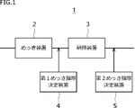
- FIG. 1 is an overall view of a textured plated steel sheet manufacturing apparatus according to a first embodiment.
- FIG. 2 is a cross-sectional view showing a schematic configuration of an example of an electrogalvanizing apparatus.
- FIG. 3 is a side view showing a schematic configuration of an example of a hot dip galvanizing apparatus.
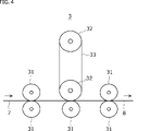
- FIG. 4 is a cross-sectional view showing a schematic configuration of an example of a grinding device.
- FIG. 5 is an overall view of a textured plated steel sheet manufacturing apparatus having a control device according to the second embodiment.
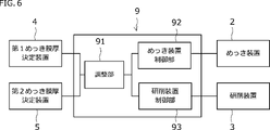
- FIG. 6 is a functional block diagram of the control device.
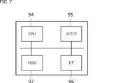
- FIG. 7 is a functional block diagram showing an example of the hardware configuration of the control device.
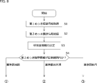
- FIG. 8 is an operation flow chart of a textured plated steel sheet manufacturing apparatus having a control device.
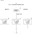
- FIG. 9 is an operation flow diagram of a textured plated steel sheet manufacturing apparatus having a control device when the second plating film thickness information exceeds the reference range.
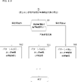
- FIG. 10 is an operation flow diagram of a textured plated steel sheet manufacturing apparatus having a control device when the second plating film thickness information is less than the reference range.
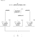
- FIG. 11 is an operation flow diagram of a textured plated steel sheet manufacturing apparatus having a control device when the second plating film thickness information is within the reference range.
- a method of manufacturing a textured plated steel sheet includes, for example, a plating layer forming step and a grinding step after the plating layer forming step.
- a plated steel sheet is manufactured by forming a plated layer on the surface of the steel sheet.
- a grinding process is implemented after a plating layer formation process. In the grinding step, for example, the surface of the plating layer of the plated steel sheet is ground to form a texture on the surface of the plating layer.
- the texture is a pattern formed by unevenness on the surface of the plating layer.
- Textures include, for example, hairlines and vibrations.
- a hairline is a pattern formed by a large number of fine linear grooves.
- Vibration is a pattern formed by a large number of fine arcuate grooves.
- the plating layer of the textured plated steel sheet is ground after being formed on the surface of the steel sheet. That is, the textured plated steel sheet is provided with a plated layer having a final thickness after being formed and ground.
- the plating layer of the textured plated steel sheet enhances the corrosion resistance of the textured plated steel sheet. If the final film thickness of the plating layer is less than a certain value, that is, if the final film thickness is insufficient, the corrosion resistance of the textured plated steel sheet is lowered. Therefore, if the final film thickness of the plating layer is less than a certain value, the product will be defective.
- the texture is sufficiently formed. In this case, the design of the plated steel sheet with texture is enhanced.
- the present inventors considered that the final film thickness of the plating layer would be a certain value or less if the plating layer was sufficiently ground.
- the present inventors set a reference range for the final film thickness of the plated layer of the textured plated steel sheet.
- the present inventors thought that by adjusting the operating conditions based on the final film thickness of the plating layer, product defects due to insufficient final film thickness of the plating layer and poor appearance could be suppressed.
- the final film thickness of the plating layer is insufficient. Even if the plating amount of the plating layer formed in the plating layer forming step is increased in order to increase the final thickness of the plating layer, the final thickness of the plating layer may be less than the reference range. It is a case where the grinding amount of the plated layer ground in the grinding process is too large. On the other hand, if the grinding amount of the plating layer to be ground in the grinding process is reduced in order to increase the final film thickness of the plating layer, the texture may not be sufficiently formed, resulting in poor appearance. That is when the plating amount of the plating layer formed in the plating layer forming step is too small. In this case, it is necessary to increase the grinding amount of the plating layer to be ground in the grinding step and at the same time increase the plating amount of the plating layer to be formed in the plating layer forming step.
- the final film thickness of the plating layer may be less than the standard range. That is when the plating amount of the plating layer formed in the plating layer forming step is too small. In this case, it is necessary to increase the grinding amount of the plating layer to be ground in the grinding step and at the same time increase the plating amount of the plating layer to be formed in the plating layer forming step.
- the final film thickness of the plating layer cannot be used as an indicator of the corrosion resistance and designability of textured plated steel sheets.
- the final film thickness and appearance of the plating layer include (1) the plating amount of the plating layer formed in the plating layer forming process, and (2) the grinding amount of the plating layer ground in the grinding process. It was found that two factors of The present inventors found that by measuring only the final thickness of the plating layer, any of (1) and / or (2) causes product defects due to insufficient final thickness of the plating layer and / or poor appearance. It was found that it was not possible to identify whether it was occurring.
- the inventors investigated a method to solve this problem.
- the information about the film thickness of the plating layer of the plated steel sheet after the plating layer forming process and before the grinding process is referred to as first plating film thickness information.
- Information about the film thickness of the plating layer of the plated steel sheet after the grinding process is referred to as second plating film thickness information.
- the present inventors can obtain not only the second plating film thickness information about the plating film thickness after grinding but also the first plating film thickness information about the plating film thickness before grinding, so that the final film of the plating layer We thought that it would be possible to quickly identify the cause of product defects due to insufficient thickness and/or poor appearance.
- a textured plated steel sheet manufacturing apparatus used in the above textured plated steel sheet manufacturing method includes, for example, a plating apparatus and a grinding apparatus.
- a plating apparatus forms a plating layer on the surface of a steel sheet to manufacture a plated steel sheet.
- the grinding device is arranged downstream of the plating device and grinds the surface of the plating layer of the plated steel sheet to form a texture on the surface of the plating layer.
- the present inventors considered that the textured plated steel sheet manufacturing apparatus should further include a first plating film thickness determining device and a second plating film thickness determining device.
- the first plating film thickness determination device determines first plating film thickness information regarding the film thickness of the plating layer before grinding, and outputs the first plating film thickness information.
- the second plating film thickness determination device is arranged downstream of the grinding device, determines second plating film thickness information regarding the thickness of the ground plating layer, and outputs the second plating film thickness information. If it is a manufacturing apparatus for a plated steel sheet with texture having the above configuration, (1) the amount of plating of the plating layer formed in the plating layer forming step and / or (2) the amount of grinding of the plating layer ground in the grinding step It is considered that it is easy to identify which one of ,
- the method for manufacturing a textured plated steel sheet according to the present embodiment, completed based on the above knowledge, has the following configuration.
- [2] A method for producing a textured plated steel sheet according to [1],
- the adjustment step Based on the first plating film thickness information and the second plating film thickness information, obtain grinding amount information, which is information about the grinding amount in the grinding step, Based on the second plating film thickness information and the grinding amount information, the plating amount of the plating layer formed in the plating layer forming step and the grinding of the surface of the plating layer ground in the grinding step adjust the amount of A method for producing a textured galvanized steel sheet.
- [3] A method for producing a plated steel sheet with texture according to [2], In the adjustment step, When the second plating film thickness information exceeds the reference range and the grinding amount information exceeds the reference range, the plating amount of the plating layer formed in the plating layer forming step is reduced, and the grinding is performed.
- Adjust to reduce the grinding amount of the surface of the plating layer ground in the process When the second plating film thickness information exceeds the reference range and the grinding amount information is less than the reference range, the plating amount of the plating layer formed in the plating layer forming step is maintained, and Adjusting to increase the grinding amount of the surface of the plating layer ground in the grinding step, When the second plating film thickness information exceeds the reference range and the grinding amount information is within the reference range, the plating amount of the plating layer formed in the plating layer forming step is reduced, and the grinding is performed.
- Adjust to maintain the amount of grinding of the surface of the plating layer ground in the process When the second plating film thickness information is less than the reference range and the grinding amount information is greater than the reference range, the plating amount of the plating layer formed in the plating layer forming step is maintained, and Adjusting to reduce the grinding amount of the surface of the plating layer ground in the grinding step, When the second plating film thickness information is less than the reference range and the grinding amount information is less than the reference range, the plating amount of the plating layer formed in the plating layer forming step is increased, and the grinding is performed.
- Adjust to increase the grinding amount of the surface of the plating layer ground in the process When the second plating thickness information is less than the reference range and the grinding amount information is within the reference range, the plating amount of the plating layer formed in the plating layer forming step is increased, and the grinding is performed.
- [4] A method for producing a textured plated steel sheet according to any one of [1] to [3], In the plating film thickness determination step, After the plating layer forming step and before the grinding step, the thickness of the plating layer of the plated steel sheet is measured, and the measured thickness is used as the first plating thickness information. A method for producing a textured galvanized steel sheet.
- [5] A method for producing a textured plated steel sheet according to any one of [1] to [4], In the plating film thickness determination step, Measure the film thickness of the plating layer of the plated steel sheet after the grinding step, and use the measured film thickness as the second plating film thickness information, A method for producing a textured galvanized steel sheet.
- the plating layer is formed by the electroplating method,
- the plating film thickness determination step In the plating layer forming step, the metal ion concentration in the plating solution, the threading speed of the steel sheet into the plating solution, the width direction length of the steel sheet, the current density, the current efficiency, and / or the plating solution determining the first plating film thickness information based on the temperature;
- a method for producing a textured galvanized steel sheet is any one of [1] to [5]
- the plating layer is formed by the electroplating method
- the plating film thickness determination step In the plating layer forming step, the metal ion concentration in the plating solution, the threading speed of the steel sheet into the plating solution, the width direction length of the steel sheet, the current density, the current efficiency, and / or the plating solution determining the first plating film thickness information based on the temperature;
- the plating layer is formed by the hot dip plating method,
- the plating film thickness determination step In the plating layer forming step, the first plating thickness information is determined based on the threading speed of the steel sheet into the plating bath, the collision pressure of the wiping gas, and / or the reduction ratio in the skin pass mill.
- a method for producing a textured plated steel sheet according to [9] In the appearance evaluation step, Two glosses, the glossiness of the surface of the plated steel sheet measured in the longitudinal direction of the plated steel sheet and the glossiness of the surface of the plated steel sheet measured in the width direction of the plated steel sheet. evaluating the appearance of the plated steel sheet based on the degree of A method for producing a textured galvanized steel sheet.
- a method for producing a textured plated steel sheet In the adjustment step, Plating of the plating layer formed in the plating layer forming step based on the first plating thickness information, the second plating thickness information, and the glossiness of the surface of the plated steel sheet after the grinding step and adjusting the grinding amount of the surface of the plating layer to be ground in the grinding step; A method for producing a textured galvanized steel sheet.
- a plating apparatus that performs hot dip plating or electroplating to form a plating layer on the surface of a steel sheet to manufacture a plated steel sheet; a grinding device disposed downstream of the plating device for grinding the surface of the plating layer of the plated steel sheet to form a texture on the surface of the plating layer; a first plating film thickness determination device that determines first plating film thickness information regarding the film thickness of the plating layer before grinding and outputs the first plating film thickness information; A second plating film thickness determining device arranged downstream of the grinding device, determining second plating film thickness information regarding the film thickness of the ground plating layer, and outputting the second plating film thickness information, Manufacturing equipment for textured galvanized steel sheets.
- the textured plated steel sheet manufacturing apparatus further comprising: A control device that controls the plating device and the grinding device, The control device is Based on the first plating film thickness information and the second plating film thickness information, controlling the plating device to adjust the plating amount of the plating layer formed on the surface of the steel sheet by the plating device, and Based on the first plating film thickness information and the second plating film thickness information, controlling the grinding device to adjust the grinding amount of the surface of the plating layer to be ground by the grinding device; Manufacturing equipment for textured galvanized steel sheets.
- the textured plated steel sheet manufacturing apparatus is Based on the first plating film thickness information and the second plating film thickness information, obtain grinding amount information, which is information about the grinding amount in the grinding device, Based on the second plating film thickness information and the grinding amount information, controlling the plating device to adjust the plating amount of the plating layer formed on the surface of the steel sheet by the plating device, and 2 Based on the plating film thickness information and the grinding amount information, controlling the grinding device to adjust the grinding amount of the surface of the plating layer ground by the grinding device; Manufacturing equipment for textured galvanized steel sheets.
- the control device is controlling the plating apparatus to reduce the plating amount of the plating layer formed by the plating apparatus when the second plating film thickness information exceeds the reference range and the grinding amount information exceeds the reference range; and controlling the grinding device to reduce the grinding amount of the surface of the plating layer ground by the grinding device,
- the plating apparatus is controlled to maintain the plating amount of the plating layer formed by the plating apparatus.
- controlling the grinding device to increase the grinding amount of the surface of the plating layer ground by the grinding device controlling the plating apparatus to reduce the plating amount of the plating layer formed by the plating apparatus when the second plating film thickness information exceeds the reference range and the grinding amount information is within the reference range; and controlling the grinding device to maintain the amount of grinding of the surface of the plating layer ground by the grinding device, Controlling the plating apparatus to maintain the plating amount of the plating layer formed by the plating apparatus when the second plating film thickness information is less than the reference range and the grinding amount information is above the reference range and controlling the grinding device to reduce the grinding amount of the surface of the plating layer ground by the grinding device, controlling the plating apparatus to increase the plating amount of the plating layer formed by the plating apparatus when the second plating film thickness information is less than the reference range and the grinding amount information is less than the reference range; and controlling the grinding device to increase the grinding amount of the surface of the plating layer ground by the grinding device, controlling the plating apparatus to increase the plating amount of the plating layer formed by
- [12] The apparatus for producing a plated steel sheet with texture according to any one of [12] to [15], further comprising: A coating film forming device disposed downstream of the grinding device and forming a coating film on the surface of the ground plating layer, Manufacturing equipment for textured galvanized steel sheets.
- the textured plated steel sheet manufacturing apparatus is A gloss meter that measures the glossiness of the surface of the plated steel sheet in the longitudinal direction of the plated steel sheet, and a gloss meter that measures the glossiness of the surface of the plated steel sheet in the width direction of the plated steel sheet. are two glossmeters of a degree meter, Manufacturing equipment for textured galvanized steel sheets.
- the textured plated steel sheet manufacturing apparatus is Based on the first plating film thickness information, the second plating film thickness information, and the glossiness of the surface of the plated steel sheet, the plating amount of the plating layer formed on the surface of the steel sheet by the plating apparatus is determined. Control the plating device to adjust, and based on the first plating film thickness information, the second plating film thickness information, and the glossiness of the surface of the plated steel sheet, the plating to be ground by the grinding device controlling the grinding device to adjust the amount of grinding of the surface of the layer; Manufacturing equipment for textured galvanized steel sheets.
- FIG. 1 is an overall view of a textured plated steel sheet manufacturing apparatus according to a first embodiment.
- a textured plated steel sheet manufacturing apparatus 1 includes a plating device 2 , a grinding device 3 , a first plating film thickness determining device 4 , and a second plating film thickness determining device 5 .
- the textured plated steel sheet manufacturing apparatus 1 of the present embodiment is a continuous line type manufacturing apparatus.
- the plating device 2 and the grinding device 3 are arranged on the same continuous line.
- the grinding device 3 is arranged downstream of the plating device 2 .
- a straight line in FIG. 1 indicates a production line.
- the textured plated steel sheet manufacturing apparatus 1 of the present embodiment includes an uncoiling device and a winding device (not shown).
- the uncoiling device is arranged upstream of the plating device 2 and unwinds the prepared steel sheet coil.
- a winding device is arranged downstream of the grinding device 3 and winds the produced textured plated steel sheet into a coil. Since the textured plated steel sheet manufacturing apparatus 1 is a continuous line type, a winding device and an uncoiling device are not arranged between the plating device 2 and the grinding device 3 .
- the plating apparatus 2 performs hot dip plating or electroplating to form a plating layer on the surface of the steel sheet to manufacture the plated steel sheet.
- Hot-dip plating is, for example, selected from the group consisting of hot-dip galvanizing and hot-dip aluminum plating.
- Electroplating is for example selected from the group consisting of electrogalvanizing, electrocopper plating and electronickel plating.
- the plating device 2 is not particularly limited as long as it is a plating device 2 that performs hot dip plating or electroplating.
- the plating apparatus 2 is a hot dip galvanizing apparatus that performs hot dip galvanizing or an electrogalvanizing apparatus that performs electrogalvanizing.
- the case of using an electrogalvanizing apparatus and the case of using a hot dip galvanizing apparatus will be described.
- FIG. 2 is a cross-sectional view showing a schematic configuration of an example of the electrogalvanizing apparatus 200.
- electrogalvanizing apparatus 200 includes multiple conductor rolls 201 , multiple anodes 202 , and multiple plating tanks 203 .
- the conveying direction of the steel sheet 6 conveyed into the electrogalvanizing apparatus 200 is changed downward by the conductor rolls 201 .
- the steel sheet 6 passes through the vicinity of the anode 202 and is continuously conveyed into the plating tank 203 .
- a zinc plating solution is stored in the plating tank 203 .
- Anode 202 is immersed in a zinc plating solution.
- electrogalvanizing apparatus 200 comprises a plurality of plating tanks 203 .
- a galvanized layer is formed on the steel plate 6 each time it passes through the plurality of plating tanks 203 .
- plated steel sheets 7 are continuously produced.
- the electrogalvanizing apparatus 200 in FIG. 2 includes a plurality of plating tanks 203.
- the number of plating tanks 203 may be one. 2
- the plating tank 203 has an opening at the top.
- the steel plate 6 is conveyed into the plating tank 203 through the upper opening of the plating tank 203 .
- the steel plate 6 or the plated steel plate 7 is carried out of the plating tank 203 through the upper opening of the plating tank 203 .
- the plating tank 203 in FIG. 2 is a so-called vertical plating tank 203 .
- the plating tank 203 may be a so-called horizontal plating tank 203 having one opening on each of two opposing sides.
- the steel sheet 6 is conveyed into the plating tank 203 through an opening on one side of the plating tank 203 .
- the steel sheet 6 or plated steel sheet 7 is carried out of the plating tank 203 through the opening on the other side of the plating tank 203 .
- FIG. 3 is a side view showing a schematic configuration of an example of the hot dip galvanizing apparatus 210.
- a hot dip galvanizing apparatus 210 includes a hot dip galvanizing pot 211, a sink roll 212, a support roll 213, a gas wiping apparatus 214, a turndown roll 215, a top roll 216, and a plurality of transport rolls. 217 and a skin pass mill 218 .
- a hot dip galvanizing bath is stored in the hot dip zinc pot 211 .
- the conveying direction of the steel sheet 6 conveyed into the hot-dip galvanizing apparatus 210 is changed downward by the turndown rolls 215 .
- the steel sheet 6 is continuously immersed in the hot dip galvanizing bath stored in the hot dip zinc pot 211 .
- a sink roll 212 is arranged inside the molten zinc pot 211 .
- the sink roll 212 is immersed in a hot dip galvanizing bath.
- the sink roll 212 changes the conveying direction of the steel plate 6 from downward to upward.
- the support roll 213 is placed above the sink roll 212 in the hot dip galvanizing bath.
- the support rolls 213 sandwich the steel plate 6 and support the steel plate 6 conveyed upward.
- the gas wiping device 214 is arranged above the liquid surface of the hot-dip galvanizing bath.
- the gas wiping device 214 comprises a pair of gas injectors.
- a pair of gas injection devices have gas injection nozzles facing each other.
- the steel plate 6 passes between a pair of gas injection nozzles of the gas wiping device 214 .
- a pair of gas injection nozzles spray a wiping gas onto the surface of the steel sheet 6 pulled up from the hot-dip galvanizing bath. As a result, part of the molten zinc adhering to the surface of the steel plate 6 is scraped off.
- the steel plate 7 from which part of the molten zinc on the surface has been scraped off is transported to the skin pass mill 218 by the top roll 216 and transport rolls 217 .
- the skin pass mill 218 includes a pair of work rolls and a pair of backup rolls.
- a pair of work rolls includes an upper work roll 219 and a lower work roll 220 .
- a pair of backup rolls includes an upper backup roll 221 and a lower backup roll 222 .
- the steel plate 6 is transported between the upper work roll 219 and the lower work roll 220 by the transport roll 217 . Sandwiched between the upper work roll 219 and the lower work roll 220, the steel plate 6 is rolled down. Thus, plated steel sheets 7 are continuously produced.
- the hot-dip galvanizing apparatus 210 may further include an alloying furnace and a cooling furnace.
- the grinding device 3 is arranged downstream of the plating device 2 and grinds the surface of the plating layer of the plated steel sheet 7 to form a texture on the surface of the plating layer. Textures include, for example, hairlines and vibrations.
- FIG. 4 is a cross-sectional view showing a schematic configuration of an example of the grinding device 3.
- grinding device 3 includes a plurality of transport rolls 31 , a pair of contact rolls 32 and a ring-shaped polishing belt 33 .
- a pair of contact rolls 32 hold a ring-shaped polishing belt 33 .
- a ring-shaped polishing belt 33 moves between the pair of contact rolls 32 by rotating the pair of contact rolls 32 .
- the plated steel sheet 7 is transported by transport rolls 31 .
- the plated steel sheet 7 is conveyed by the conveying roll 31 between the conveying roll 31 and the ring-shaped polishing belt 33 .
- the plated steel sheet 7 is pressed against the ring-shaped polishing belt 33 by one of the pair of contact rolls 32 and the transport roll 31 .
- the ring-shaped polishing belt 33 grinds the plating layer on the surface of the plated steel sheet 7 . Thereby, a texture is formed on the surface of the plating layer.
- the grinding device 3 in FIG. 4 is a grinding belt type grinding device 3 .
- the grinding device 3 is not limited to this.
- the grinding device 3 may, for example, comprise grinding brushes.
- the first plating film thickness determination device 4 determines first plating film thickness information regarding the film thickness of the plating layer before grinding, and outputs the first plating film thickness information.
- the first plating film thickness determination device 4 may have a screen, and the first plating film thickness information may be output on this screen.
- the first plating film thickness information is information about the film thickness of the plating layer before grinding.
- the first plating film thickness information may be, for example, the film thickness ( ⁇ m) of the plating layer before grinding, the plating deposition amount (g/m 2 ) of the plating layer before grinding, or the plating It may be the plating conditions in the apparatus 2 .
- the plating conditions in the plating apparatus 2 are, for example, the concentration of metal ions in the plating solution, the speed at which the steel sheet is passed through the plating solution, the length of the steel sheet in the width direction, the temperature and/or pH of the plating solution, and the like.
- the plating conditions are the concentration of metal ions in the plating solution, the speed of passing the steel sheet into the plating solution, the length of the steel sheet in the width direction, the current density, the current It may be the efficiency and/or the temperature of the plating solution.
- the plating conditions are the threading speed of the steel sheet into the plating solution, the collision pressure of the wiping gas, and/or the reduction ratio in the skin pass mill 218. may That is, the first plating film thickness information includes the plating film thickness before grinding and all information that can be used for estimating the plating film thickness before grinding.
- the first plating film thickness determination device 4 determines first plating film thickness information regarding the film thickness of the plating layer before grinding.
- the first plating film thickness information may be determined by measurement. Specifically, after the plating layer is formed by the plating device 2, the thickness ( ⁇ m) of the plating layer before grinding the plating layer by the grinding device 3, or the thickness of the plating layer before grinding The plating adhesion amount (g/m 2 ) may be measured, and the measured film thickness ( ⁇ m) or the plating adhesion amount (g/m 2 ) may be determined as the first plating thickness information.
- the first plating film thickness determination device 4 is, for example, a fluorescent X-ray film thickness gauge.
- the first plating film thickness information may be plating conditions in the plating apparatus 2 .
- the first plating film thickness determining device 4 may measure the plating conditions.
- the first plating film thickness determination device 4 is, for example, a voltmeter, an ammeter, an ion meter, a thermometer, or a gas pressure gauge.
- the film thickness ( ⁇ m) of the plating layer before grinding or the plating deposition amount (g/m 2 ) of the plating layer before grinding is calculated, and is used as the first plating film thickness information. may decide.
- the first plating film thickness determination device 4 measures the plating conditions, and based on the measured plating conditions, the film thickness ( ⁇ m) of the plating layer before grinding, or the plating adhesion amount of the plating layer before grinding (g / m 2 ) is calculated and output.
- the first plating film thickness determination device 4 may include a memory that stores a plating film thickness determination table.
- the first plating film thickness determination device 4 for example, in the plating film thickness determination table, corresponds to the threading speed of the steel sheet and the width direction length of the steel sheet input in advance, and the measured plating conditions,
- the film thickness ( ⁇ m) of the plating layer before grinding or the plating deposition amount (g/m 2 ) of the plating layer before grinding may be specified to determine the first plating thickness information.
- the first plating film thickness determination device 4 uses a pre-stored calculation program from the pre-inputted plate threading speed, the width direction length of the steel plate, and the measured plating conditions, The film thickness ( ⁇ m) of the plating layer before grinding or the plating deposition amount (g/m 2 ) of the plating layer before grinding may be calculated to determine the first plating thickness information.
- the second plating film thickness determination device 5 is arranged downstream of the grinding device 3, determines second plating film thickness information regarding the thickness of the ground plating layer, and outputs the second plating film thickness information.
- the second plating film thickness determination device 5 may have a screen, and the second plating film thickness information may be output on this screen.
- the second plating film thickness information may be, for example, the film thickness ( ⁇ m) of the plated layer after grinding, or may be the plating deposition amount (g/m 2 ) of the plated layer after grinding.
- the second plating film thickness information is determined by measurement. Specifically, the film thickness ( ⁇ m) of the plating layer after grinding the plating layer by the grinding device 3, or the plating adhesion amount (g/m 2 ) of the plating layer after grinding is measured, and the measured film thickness ( ⁇ m) or plating deposition amount (g/m 2 ) may be determined as the second plating film thickness information.
- the second plating film thickness determination device 5 is, for example, a fluorescent X-ray film thickness gauge.
- the apparatus 1 for manufacturing the textured plated steel sheet described above includes not only the second plating film thickness determining device 5 but also the first plating film thickness determining device 4 . Therefore, when a product defect occurs due to insufficient film thickness of the plating layer and poor appearance, (1) the amount of plating of the plating layer formed in the plating layer forming process and (2) the amount of grinding in the grinding process It is easy to identify which of the two factors, ie, the amount of grinding of the plating layer, caused the defective product.
- the method for manufacturing a textured plated steel sheet according to the present embodiment includes a plating layer forming step, a grinding step, a plating film thickness determining step, and an adjusting step.
- the plated steel sheet 7 is manufactured by forming a plated layer on the surface of the steel sheet 6 by electroplating or hot dipping.
- the plating apparatus 2 is, for example, an electrogalvanizing apparatus 200 .
- the plating apparatus 2 is, for example, a hot-dip galvanizing apparatus 210 .
- Electro-galvanizing method As an example, a case where a plated layer is formed on the surface of the steel sheet 6 by electrogalvanizing to manufacture the plated steel sheet 7 will be described.
- the electrogalvanizing method may be implemented by a well-known method.
- the electrogalvanizing method also includes an electrogalvanizing method.
- a well-known plating solution is sufficient for the plating solution used in the electrogalvanizing method. Examples of electrogalvanizing solutions include sulfuric acid baths, chloride baths, zincate baths, cyanide baths, pyrophosphoric acid baths, boric acid baths, citric acid baths, other complex baths and combinations thereof.
- the electrolytic zinc alloy plating solution contains, for example, Zn ions and one or more single ions or complex ions selected from the group consisting of Fe, Ni, Co, Cr and C.
- an appropriate organic additive or the like may be added to the plating solution.
- the plating solution used in the electrogalvanizing method contains zinc sulfate heptahydrate: 200 to 400 g/L, sodium sulfate: 15 to 100 g/L, and has a pH of 1.0 to 2.5. can.
- the zinc ion concentration, temperature, pH, threading speed of the steel sheet 6, current density, etc. in the electrogalvanizing solution and the electrogalvanizing solution can be appropriately set.
- the zinc ion concentration in the plating solution is, for example, 0.8-1.5 mol/L.
- the temperature of the plating solution is, for example, 40-60.degree.
- the threading speed of the steel plate 6 is, for example, 20 to 200 m/min. Current densities are, for example, 10-200 A/dm 2 .
- the thickness of the plating layer formed by performing the electrogalvanizing method for example, adjusts the threading speed and/or the current density of the steel sheet 6 into the plating solution during the electrogalvanizing method. can be adjusted. Thereby, a plating layer is formed on the surface of the steel sheet 6, and the plated steel sheet 7 can be manufactured.
- the hot-dip galvanizing method may be implemented by a well-known method.
- a well-known plating bath is sufficient for the plating bath used in the hot-dip galvanizing method.
- the hot-dip galvanizing bath can be, for example, a plating bath containing Al with the balance being Zn and impurities. Impurities are, for example, Fe.
- the hot-dip galvanizing bath contains Mg, Si, Ca, Y, La, Ce, Sn, Bi, In, Cr, Ti, Ni, Co, V, Nb, Cu, Mn, Sr , Sb, Pb, and B.
- the Al concentration, Fe concentration, concentration of other elements, temperature, pH, threading speed of the steel sheet 6, impingement pressure of the wiping gas, and reduction ratio in the skin pass mill 218 in the hot dip galvanizing bath are It can be set as appropriate.
- Al concentration is, for example, 0.1 to 60.0% by mass.
- the Fe concentration is, for example, 0.01-0.5% by mass.
- the hot dip galvanizing bath contains Mg, Si, Ca, Y, La, Ce, Sn, Bi, In, Cr, Ti, Ni, Co, V, Nb, Cu, Mn, Sr,
- the total content of these elements is, for example, 0.0 to 15.0% by mass.
- the temperature of the hot-dip galvanizing bath is, for example, 430-630°C.
- the threading speed of the steel plate 6 is, for example, 60 to 150 m/min.
- the collision pressure of the wiping gas is, for example, 0-200 kPa.
- the rolling reduction in the skin pass mill 218 is, for example, 0 to 3.0%.
- the thickness of the coating layer formed by performing the hot-dip galvanizing method is, for example, the threading speed of the steel sheet 6 into the plating solution, the collision pressure of the wiping gas, and/or , can be adjusted by adjusting the rolling reduction in the skin pass mill 218 . Thereby, a plating layer is formed on the surface of the steel sheet 6, and the plated steel sheet 7 can be manufactured.
- the surface of the plating layer of the plated steel sheet 7 is ground to form a texture on the surface of the plating layer.
- a texture is, for example, a hairline.
- the grinding device 3 having the grinding belt 33 grinds the surface of the plating layer to form a hairline on the surface of the plating layer.
- the threading speed of the plated steel sheet 7 to the grinding device 3, the rotation speed of the contact roll 32, and the pressing force of the contact roll 32 against the plated steel sheet 7 can be adjusted as appropriate.
- the plated steel sheet 7 is passed through the grinding device 3 at a speed of, for example, 20 to 200 m/min.
- the rotation speed of the contact roll 32 is, for example, 10-1500 rpm.
- the pressing force of the contact roll 32 against the plated steel sheet 7 is, for example, 0.01 to 0.10 MPa.
- the grinding amount of the plated layer ground in the grinding step can be adjusted by adjusting the rotation speed of the contact roll 32 and the rolling force of pressing the contact roll 32 against the plated steel sheet 7 .
- the amount of grinding can be adjusted, for example, by adjusting the rotational speed of the grinding brush and/or the rolling force of pressing the grinding brush against the plated steel sheet 7 .
- first plating film thickness information related to the film thickness of the plating layer of the plated steel sheet 7 after the plating layer forming step and before the grinding step, and the film thickness of the plating layer of the plated steel sheet 8 after the grinding step. and the second plating film thickness information relating to.
- the first plating film thickness information may be determined by measuring the film thickness of the plating layer of the plated steel sheet after the plating layer forming process and before the grinding process.
- the first plating film thickness information may be plating conditions in the plating layer forming step.
- the first plating film thickness information may be determined based on plating conditions in the plating layer forming step.
- the second plating film thickness information is determined by measuring the film thickness of the plating layer of the plated steel sheet after the grinding process.
- Adjustment process the amount of plating of the plating layer formed in the plating layer forming step and the amount of grinding of the surface of the plating layer to be ground in the grinding step are adjusted based on the first and second plating film thickness information.
- the plating amount of the plating layer formed in the plating layer forming step is reduced and the grinding step is performed.
- the first plating film thickness information is checked, and if the first plating film thickness information exceeds the reference range, the plating layer is formed in the plating layer forming step while maintaining the grinding amount of the plating layer to be ground in the grinding step. After that, check the second plating thickness information, and if the second plating thickness information exceeds the reference range, grind while maintaining the plating amount of the plating layer formed in the plating layer forming process The grinding amount of the plating layer ground in the process may be increased.
- the plating amount of the plating layer formed in the plating layer forming step can be reduced by, for example, the following method.
- the threading speed (m/min) of the steel sheet 6 into the plating solution may be increased.
- the current density (A/dm 2 ) may be lowered. Only one of these conditions may be adjusted, or a combination of multiple conditions may be adjusted.
- the plating apparatus 2 is the hot-dip galvanizing apparatus 210
- the plating amount of the plating layer formed in the plating layer forming step can be reduced by, for example, the following method.
- the threading speed (m/min) of the steel sheet 6 into the plating solution may be increased.
- the impingement pressure of the wiping gas may be increased.
- the reduction in skin pass mill 218 may be increased. Only one of these conditions may be adjusted, or a combination of multiple conditions may be adjusted.
- the speed (m/min) of the plated steel sheet 7 passing through the grinding device 3 may be decreased, or the rotation speed (rpm) of the contact roll 32 may be reduced. may be increased, or the rolling force (MPa) of pressing the contact roll 32 against the plated steel sheet 7 may be increased.
- the rotational speed of the grinding brush may be increased, or the pressing force of the grinding brush against the plated steel sheet 7 may be increased. Only one of these conditions may be adjusted, or a combination of multiple conditions may be adjusted.
- the plating amount of the plating layer formed in the plating layer forming process is reduced and the grinding process is performed. You may reduce the amount of grinding of the plating layer which carries out. In this case, the reduction of the plating amount of the plating layer formed in the plating layer forming step and the reduction of the grinding amount of the plating layer ground in the grinding step may be performed at the same time.
- the first plating film thickness information is checked, and if the first plating film thickness information exceeds the reference range, the plating layer is formed in the plating layer forming step while maintaining the grinding amount of the plating layer to be ground in the grinding step.
- the plated steel sheet 7 passing speed (m/min) to the grinding device 3 may be increased, or the rotation speed (rpm) of the contact roll 32 may be increased. may be slowed down, or the rolling force (MPa) of pressing the contact roll 32 against the plated steel sheet 7 may be lowered.
- the grinding device 3 is equipped with a grinding brush, the number of revolutions of the grinding brush may be slowed down, or the pressing force of the grinding brush pressed against the plated steel sheet 7 may be lowered. Only one of these conditions may be adjusted, or a combination of multiple conditions may be adjusted.
- the plating amount of the plating layer formed in the plating layer forming process is maintained, and in the grinding process The amount of grinding of the plating layer to be ground may be increased.
- the plating amount of the plating layer formed in the plating layer forming process is maintained, and in the grinding process Maintain the grinding amount of the plating layer to be ground.
- the plating amount of the plating layer formed in the plating layer forming process is maintained, and in the grinding process The amount of grinding of the plating layer to be ground may be reduced.
- the plating amount of the plating layer formed in the plating layer forming step is increased and the grinding step is performed. You may increase the amount of grinding of the plating layer which carries out. In this case, increasing the plating amount of the plating layer formed in the plating layer forming step and increasing the grinding amount of the plating layer ground in the grinding step may be performed at the same time.
- the first plating film thickness information is checked, and if the first plating film thickness information is less than the reference range, the plating layer is formed in the plating layer forming step while maintaining the grinding amount of the plating layer to be ground in the grinding step. After that, check the second plating thickness information, and if the second plating thickness information exceeds the standard range, grind while maintaining the plating amount of the plating layer formed in the plating layer forming process The grinding amount of the plating layer ground in the process may be increased.
- the plating amount of the plating layer formed in the plating layer forming step can be increased by, for example, the following method.
- the threading speed (m/min) of the steel sheet 6 into the plating solution may be decreased.
- current density (A/dm 2 ) may be increased. Only one of these conditions may be adjusted, or a combination of multiple conditions may be adjusted.
- the plating apparatus 2 is the hot-dip galvanizing apparatus 210
- the plating amount of the plating layer formed in the plating layer forming step can be increased by, for example, the following method.
- the threading speed (m/min) of the steel sheet 6 into the plating solution may be decreased.
- the impingement pressure of the wiping gas may be reduced.
- the reduction in skin pass mill 218 may be reduced. Only one of these conditions may be adjusted, or a combination of multiple conditions may be adjusted.
- the plating amount of the plating layer formed in the plating layer forming step is increased and the grinding step is performed. You may reduce the amount of grinding of the plating layer which carries out. In this case, increasing the plating amount of the plating layer formed in the plating layer forming step and reducing the grinding amount of the plating layer ground in the grinding step may be performed at the same time.
- the first plating film thickness information is checked, and if the first plating film thickness information is less than the reference range, the plating layer is formed in the plating layer forming step while maintaining the grinding amount of the plating layer to be ground in the grinding step.
- the method for manufacturing a textured plated steel sheet according to the present embodiment is carried out using a continuous line type textured plated steel sheet manufacturing apparatus. Therefore, the coiling of the steel sheet and the unwinding of the steel sheet are not performed between the plating layer forming process and the grinding process. Further, in the method for manufacturing a textured plated steel sheet of the present embodiment, in the adjustment step, the first and second plating film thicknesses are applied to the same steel sheet coil as the steel sheet coil for which the first and second plating film thickness information has been acquired. Adjust the amount of plating and the amount of grinding based on the information.
- the reference range of the first plating film thickness information can be set appropriately and is not particularly limited.
- the reference range of the first plating film thickness information may be, for example, 10 to 320 g/m 2 .
- the reference range of the first plating film thickness information is, for example, 1 to 20 kA/m 2 . good too.
- the reference range of the first plating film thickness information is, for example, 30 to 200 m/min. good.
- the reference range of the first plating film thickness information may be, for example, 0 to 200 kPa.
- the reference range of the first plating film thickness information is, for example, 0 to 3.0%. good.
- the reference range of the second plating film thickness information can be set appropriately and is not particularly limited.
- the reference range of the second plating film thickness information may be, for example, 5 to 300 g/m 2 .
- the plating film thickness determination step not only the second plating film thickness information regarding the film thickness of the plating layer after grinding, but also the film thickness of the plating layer before grinding Determining the first plating film thickness information related to the thickness, and further, in the adjustment process, based on the first and second plating film thickness information, the plating amount of the plating layer formed in the plating layer forming process and grinding in the grinding process Adjust the amount of grinding of the surface of the plating layer to be polished.
- FIG. 5 is an overall view of a textured plated steel sheet manufacturing apparatus 1 in the case of including a control device in the second embodiment.
- a textured plated steel sheet manufacturing apparatus 1 has the same configuration as the textured plated steel sheet manufacturing apparatus 1 of the first embodiment, and further includes a control device 9.
- the first plating film thickness determination device 4 outputs the first plating film thickness information to the control device 9
- the second plating film thickness determination device 5 outputs the second plating film thickness information to the control device. output to 9.
- the control device 9 controls the plating device 2 to adjust the plating amount of the plating layer formed on the surface of the steel sheet 6 by the plating device 2 based on the first plating film thickness information and the second plating film thickness information, and , based on the first plating film thickness information and the second plating film thickness information, the grinding device 3 is controlled to adjust the grinding amount of the surface of the plating layer to be ground by the grinding device 3 .
- the controller 9 is provided, the textured plated steel sheet manufacturing apparatus 1 can more easily identify the cause of the product defect due to insufficient film thickness of the plated layer and poor appearance.
- the controller 9 the textured plated steel sheet manufacturing apparatus 1 can easily suppress unnecessary manufacturing costs in addition to suppressing product defects.
- FIG. 6 is a functional block diagram of the control device 9.
- control device 9 includes an adjustment section 91 , a plating device control section 92 and a grinding device control section 93 .
- the adjustment unit 91 determines how the plating device 2 and the grinding device 3 are operated. Decide whether to control and output the result.
- the plating apparatus control section 92 controls the plating apparatus 2 based on the result determined by the adjustment section 91 .
- the plating apparatus control unit 92 controls, for example, the threading speed (m/min) of the steel sheet 6 into the plating solution and/or the current density (A/dm 2 ) is controlled.
- the plating apparatus control unit 92 controls, for example, the threading speed (m/min) of the steel sheet 6 into the plating solution, the collision pressure (kPa) of the wiping gas, and /or to control the reduction (%) in the skin pass mill 218; Thereby, the plating amount of the plating layer formed by the plating apparatus 2 is adjusted.
- the grinding device control section 93 controls the grinding device 3 based on the result determined by the adjustment section 91 .
- the grinding device control unit 93 controls, for example, the threading speed (m/min) of the plated steel sheet 7 to the grinding device 3, the rotation speed of the contact roll 32, (rpm) and the pressing force (MPa) of pressing the contact roll 32 against the plated steel sheet 7 are controlled.
- the grinding device control unit 93 controls, for example, the rotational speed of the grinding brush and the pressing force of the grinding brush against the plated steel sheet 7 . Thereby, the grinding amount of the surface of the plated layer to be ground by the grinding device 3 is adjusted.
- FIG. 7 is a functional block diagram showing an example of the hardware configuration of the control device 9.
- the control device 9 includes a central processing unit (CPU: Central Processing Unit) 94, a memory 95, an interface 96 (indicated as I/F in FIG. 7), and a hard disk 97. (displayed as HDD in FIG. 7). These structures are connected together by a bus.
- the hard disk 97 stores a plating condition adjustment program and a grinding condition adjustment program. The plating condition adjustment program and the grinding condition adjustment program are loaded into the memory 95 and executed by the CPU 94 to implement the operations of the adjusting section 91, the plating apparatus control section 92 and the grinding apparatus control section 93 described above.
- the hard disk 97 is not particularly limited as long as it is a storage medium. For example, an SSD may be used.
- FIG. 8 to 11 are operation flow diagrams of the textured plated steel sheet manufacturing apparatus 1 having the control device 9.
- FIG. 8 to 11 are operation flow diagrams of the textured plated steel sheet manufacturing apparatus 1 having the control device 9.
- the control device 9 first acquires the first plating film thickness information output from the first plating film thickness determining device 4 (S1). The control device 9 subsequently acquires the second plating film thickness information output from the second plating film thickness determining device 5 (S2). In FIG. 8, the second plating film thickness information is obtained after obtaining the first plating film thickness information. However, the control device 9 may acquire the first plating thickness information after acquiring the second plating thickness information, or may acquire the first and second plating thickness information at the same time.
- the adjustment unit 91 of the control device 9 obtains grinding amount information, which is information about the grinding amount in the grinding device 3, based on the obtained first plating film thickness information and second plating film thickness information (S3).
- first and second plating film thickness information is the film thickness ( ⁇ m) of the plating layer
- first plating film thickness information ( ⁇ m) which is the film thickness of the plating layer before grinding
- the grinding amount information ( ⁇ m) is obtained by subtracting the second plating film thickness information ( ⁇ m), which is the film thickness of the plating layer.
- the first and second plating film thickness information is the plating deposition amount (g/m 2 ).
- the adjustment unit 91 of the control device 9 determines the film thickness ( ⁇ m) of the plating layer before grinding or the thickness of the plating layer from the plating conditions of the plating device 2. You may calculate the plating adhesion amount (g/m ⁇ 2 >) before grinding. Subtract the measured second plating thickness ( ⁇ m) or second plating deposition amount (g/m 2 ) from the calculated first plating thickness ( ⁇ m) or first plating deposition amount (g/m 2 ) Thus, the grinding amount information may be obtained.
- the operation after obtaining the grinding amount information (S3) depends on any of patterns 1 to 9.
- the adjustment unit 91 of the control device 9 determines whether the second plating film thickness information is within the reference range (S4 in FIG. 8). When the second plating film thickness information exceeds the reference range (“Exceeds reference range” in S4 of FIG. 8), the adjustment unit 91 of the control device 9 subsequently determines whether the grinding amount information is within the reference range ( S5 in FIG. 9). The adjustment unit 91 of the control device 9 issues an instruction of one of patterns 1 to 3 depending on whether the grinding amount information is above the reference range, below the reference range, or within the reference range.
- the second plating film thickness information exceeds the reference range and the grinding amount information exceeds the reference range, the plating amount of the plating layer formed by the plating device 2 is too large, and the plating layer is required by the grinding device 3. Grinding more than necessary increases unnecessary costs. Therefore, considering the cost, it is preferable to change the operating conditions to reduce the plating amount of the plating layer formed by the plating device 2 and reduce the grinding amount of the plating layer to be ground by the grinding device 2 .
- the plating device 2 is controlled to reduce the plating amount of the plating layer formed by the plating device 2, and the grinding device 3 is controlled to reduce the grinding amount of the surface of the plating layer ground by the grinding device 3.
- the plating apparatus control section 92 controls the plating apparatus 2 so as to reduce the plating amount of the plating layer formed by the plating apparatus 2.
- the grinding device control unit 93 controls the grinding device 3 so as to reduce the grinding amount of the surface of the plated layer ground by the grinding device 3.
- the second plating film thickness information exceeds the reference range and the grinding amount information is less than the reference range, the surface of the plating layer is not sufficiently ground by the grinding device 3, so that the surface of the plating layer has sufficient texture. is not formed, resulting in poor appearance.
- the second plating film thickness information exceeds the reference range, it can be understood that the product defect has occurred due to the grinding amount of the plating layer ground by the grinding device 3 .
- the plating device 2 is controlled to maintain the plating amount of the plating layer formed by the plating device 2, and the grinding device 3 is controlled to increase the grinding amount of the surface of the plating layer ground by the grinding device 3.
- the grinding device control unit 93 controls the plating device 2 so as to maintain the plating amount of the plating layer formed by the plating device 2, and the surface of the plating layer to be ground by the grinding device 3
- the grinding device 3 is controlled so as to increase the grinding amount of .
- the second plating film thickness information exceeds the reference range and the grinding amount information is within the reference range, the plating amount of the plating layer formed by the plating device 2 is too large, resulting in an unnecessary increase in cost. Therefore, considering the cost, it is preferable to change the operating conditions and reduce the plating amount of the plating layer formed by the plating apparatus 2 .
- the plating device 2 is controlled to reduce the plating amount of the plating layer formed by the plating device 2, and the grinding device 3 is controlled to maintain the grinding amount of the surface of the plating layer ground by the grinding device 3.
- the plating device control unit 92 controls the plating device 2 so as to reduce the plating amount of the plating layer formed by the plating device 2, and the surface of the plating layer to be ground by the grinding device 3.
- the grinding device 3 is controlled so as to maintain the grinding amount.
- the adjustment unit 91 of the control device 9 determines whether the second plating film thickness information is within the reference range (S4 in FIG. 8). If the second plating film thickness information is less than the reference range ("less than the reference range" in S4 of FIG. 8), the adjustment unit 91 of the control device 9 subsequently determines whether the grinding amount information is within the reference range ( S9 in FIG. 10). The adjustment unit 91 of the control device 9 issues an instruction of one of patterns 4 to 6 depending on whether the grinding amount information is above the reference range, below the reference range, or within the reference range.
- the second plating film thickness information is less than the reference range and the grinding amount information is more than the reference range, the second plating film thickness information is less than the reference range. Corrosion resistance of the steel sheet is lowered, resulting in defective products. Further, in this case, since the grinding amount information exceeds the reference range, it can be understood that the product defect is caused by the grinding amount of the plating layer ground by the grinding device 3 . In this case, it is necessary to reduce the amount of the plated layer ground by the grinding device 3 by changing the operating conditions.
- the plating device 2 is controlled to maintain the plating amount of the plating layer formed by the plating device 2, and the grinding device 3 is controlled to reduce the grinding amount of the surface of the plating layer ground by the grinding device 3.
- the grinding device control unit 93 controls the plating device 2 so as to maintain the plating amount of the plating layer formed by the plating device 2, and the surface of the plating layer to be ground by the grinding device 3.
- the grinding device 3 is controlled so as to reduce the grinding amount of .
- the second plating thickness information is less than the reference range and the grinding amount information is less than the reference range, the second plating thickness information is less than the reference range. Corrosion resistance of the steel sheet is lowered, resulting in defective products. In this case, further, since the grinding amount information is less than the reference range, the surface of the plating layer is not sufficiently ground by the grinding device 3, so the texture is not formed sufficiently on the surface of the plating layer, and the appearance become defective. In addition, since the second plating film thickness information is less than the reference range, the product It can be seen that a defect has occurred. In this case, it is necessary to change the operating conditions to increase the plating amount of the plating layer formed by the plating device 2 and increase the grinding amount of the plating layer to be ground by the grinding device 3 .
- the plating device 2 is controlled to increase the plating amount of the plating layer formed by the plating device 2, and the grinding device 3 is controlled to increase the grinding amount of the surface of the plating layer ground by the grinding device 3.
- the plating apparatus control section 92 controls the plating apparatus 2 so as to increase the plating amount of the plating layer formed by the plating apparatus 2.
- the grinding device control unit 93 controls the grinding device 3 so as to increase the grinding amount of the surface of the plated layer ground by the grinding device 3.
- the second plating film thickness information is less than the reference range and the grinding amount information is within the reference range, the second plating film thickness information is less than the reference range. Corrosion resistance of the steel sheet is lowered, resulting in defective products. In this case, since the grinding amount information is within the reference range, it can be seen that the plating amount of the plating layer formed by the plating apparatus 2 is insufficient. In this case, it is necessary to increase the plating amount of the plating layer formed by the plating apparatus 2 by changing the operating conditions.
- the plating device 2 is controlled to increase the plating amount of the plating layer formed by the plating device 2, and the grinding device 3 is controlled to maintain the grinding amount of the surface of the plating layer ground by the grinding device 3. is instructed to do so.
- the plating device control unit 92 controls the plating device 2 to increase the plating amount of the plating layer formed by the plating device 2, and the surface of the plating layer to be ground by the grinding device 3.
- the grinding device 3 is controlled so as to maintain the grinding amount.
- the adjustment unit 91 of the control device 9 determines whether the second plating film thickness information is within the reference range (S4 in FIG. 8). If the second plating film thickness information is within the reference range (“within reference range” in S4 of FIG. 8), the adjustment unit 91 of the control device 9 subsequently determines whether the grinding amount information is within the reference range ( S13 in FIG. 11). The adjustment unit 91 of the control device 9 issues an instruction of one of patterns 7 to 9 depending on whether the grinding amount information is above the reference range, below the reference range, or within the reference range.
- the grinding device 3 When the second plating film thickness information is within the reference range and the grinding amount information exceeds the reference range, the grinding device 3 is grinding the surface of the plating layer more than the required amount. Therefore, unnecessary costs increase. Therefore, considering the cost, it is preferable to reduce the amount of the plating layer ground by the grinding device 3 .
- the plating device 2 is controlled to maintain the plating amount of the plating layer formed by the plating device 2, and the grinding device 3 is controlled to reduce the grinding amount of the surface of the plating layer ground by the grinding device 3.
- the grinding device control unit 93 controls the plating device 2 so as to maintain the plating amount of the plating layer formed by the plating device 2, and the surface of the plating layer to be ground by the grinding device 3.
- the grinding device 3 is controlled so as to reduce the grinding amount of .
- the grinding amount information is less than the reference range. Therefore, the surface of the plating layer is not sufficiently textured, resulting in poor appearance. Further, in this case, since the second plating film thickness information is within the reference range, it can be seen that the product defect has occurred due to the grinding amount of the plating layer ground by the grinding device 3 . In this case, it is necessary to increase the grinding amount of the plated layer ground by the grinding device 3 .
- the plating device 2 is controlled to maintain the plating amount of the plating layer formed by the plating device 2, and the grinding device 3 is controlled to increase the grinding amount of the surface of the plating layer ground by the grinding device 3.
- the grinding device control unit 93 controls the plating device 2 so as to maintain the plating amount of the plating layer formed by the plating device 2, and the surface of the plating layer to be ground by the grinding device 3.
- the grinding device 3 is controlled so as to increase the grinding amount of .
- the second plating film thickness information is within the reference range and the grinding amount information is within the reference range, there is no shortage of the final film thickness of the plating layer and no product defects due to poor appearance. are also found to be well maintained. In this case, the operating conditions should be maintained.
- the plating device 2 is controlled to maintain the plating amount of the plating layer formed by the plating device 2, and the grinding device 3 is controlled to maintain the grinding amount of the surface of the plating layer ground by the grinding device 3. You will be instructed to do so.
- the plating device control unit 92 controls the plating device 2 so as to maintain the plating amount of the plating layer formed by the plating device 2, and the surface of the plating layer to be ground by the grinding device 3.
- the grinding device 3 is controlled so as to maintain the grinding amount of .
- the textured plated steel sheet manufacturing apparatus 1 of the present embodiment is controlled by the control device 9 based on the first plating film thickness information and the second plating film thickness information. While controlling the plating device 2 to adjust the plating amount of the plating layer to be formed and controlling the grinding device 3 to adjust the grinding amount of the surface of the plating layer to be ground by the grinding device 3, the textured plated steel sheet 8 to manufacture. This makes it easier to identify the cause of the product defect due to the lack of film thickness of the plating layer and the poor appearance. In this case, it is easier to suppress product defects in which the corrosion resistance is lowered due to insufficient thickness of the plating layer and/or product defects in which the appearance is poor due to insufficient texture formation. When the controller 9 is provided, the textured plated steel sheet manufacturing apparatus 1 can easily suppress manufacturing costs in addition to product defects.
- the method of manufacturing a textured plated steel sheet provided with the control device 9 of the present embodiment is the same as that of the first embodiment except that the textured plated steel sheet manufacturing apparatus provided with the control device 9 is used.
- the control device 9 is used, but without using the control device 9, based on the first plating film thickness information and the second plating film thickness information, the information about the grinding amount in the grinding device can be obtained.
- a certain grinding amount information is obtained, and based on the second plating film thickness information and the grinding amount information, the plating amount of the plating layer formed in the plating layer forming process and the grinding amount of the surface of the plating layer ground in the grinding process are adjusted.
- You may A textured plated steel sheet manufacturing apparatus 1 used in the third embodiment is the same as that in the first embodiment.
- a method for manufacturing a textured plated steel sheet according to the third embodiment includes a plating layer forming step, a grinding step, a plating film thickness determining step, and an adjusting step. Processes other than the adjustment process are the same as in the first embodiment.
- grinding amount information which is information about the grinding amount in the grinding device, is obtained, and based on the second plating film thickness information and the grinding amount information, the plating layer formed in the plating layer forming step and the amount of grinding of the surface of the plating layer to be ground in the grinding step.
- grinding amount information is obtained based on the first plating film thickness and the second plating film thickness.
- the method of obtaining the grinding amount information is the same as in the second embodiment except that the control device 9 is not used.
- the adjustment process based on the second plating film thickness information and the grinding amount information, the plating amount of the plating layer formed in the plating layer forming process based on the following patterns 1 to 9, and the plating layer to be ground in the grinding process Adjust the amount of surface grinding.
- the plating amount of the plating layer formed in the plating layer forming process and the surface of the plating layer ground in the grinding process Adjust to maintain the amount of grinding. Specifically, the plating conditions in the plating layer forming process and the grinding conditions in the grinding process are maintained.
- the textured plated steel sheet manufacturing apparatus 1 may include a coating film forming device in addition to the plating device 2, the grinding device 3, the first plating film thickness determining device 4, and the second plating film thickness determining device 5. good.
- the coating film forming device is arranged downstream of the grinding device 3 and forms a coating film on the surface of the ground plating layer.
- the method for producing a plated steel sheet with a texture includes a coating film forming step in addition to a plating layer forming step, a grinding step, a plating film thickness determining step, and an adjusting step.
- Coating film forming step A well-known method may be used for forming the coating film.
- a paint that constitutes the organic coating is prepared.
- the prepared paint is applied onto the plated layer by a spray method, a roll coater method, a curtain coater method, an immersion pick-up method, or the like. After that, the paint on the plating layer is naturally dried or baked to form an organic coating film.
- the drying temperature, drying time, baking temperature, and baking time can be adjusted as appropriate.
- the agent for the inorganic coating film is applied onto the plating layer by a roll coater method, an immersion ringer method, a spray ringer method, an electrolytic method, or the like. Natural drying or baking drying is performed on the chemical applied on the plating layer to form an inorganic coating film.
- the drying temperature, drying time, baking temperature, and baking time can be adjusted as appropriate.
- a textured plated steel sheet manufacturing apparatus 1 includes a plating device 2, a grinding device 3, a first plating film thickness determining device 4, and a second plating film thickness determining device 5, as well as one or more gloss meters. You may prepare.
- a gloss meter is arranged downstream of the grinding device 3 to evaluate the appearance of the surface of the plated steel sheet with the ground coating layer.
- the glossiness meter measures the glossiness of the surface of the plated steel sheet in the longitudinal direction of the plated steel sheet, and the glossiness meter measures the glossiness of the surface of the plated steel sheet in the width direction of the plated steel sheet. There may be two gloss meters in total. In this case, the appearance of the surface of the plated steel sheet having the ground layer can be evaluated with higher accuracy.
- the method for producing a textured plated steel sheet includes a plating layer forming step, a grinding step, a plating film thickness determination step, and an adjustment step.
- An appearance evaluation step is provided. In the appearance evaluation step, the appearance of the plated steel sheet after the grinding step is evaluated by glossiness.
- the appearance evaluation step the appearance of the plated steel sheet after the grinding step is evaluated by glossiness.
- the glossiness of the surface of the plated steel sheet measured in the longitudinal direction of the plated steel sheet, and the glossiness of the surface of the plated steel sheet measured in the width direction of the plated steel sheet. You may evaluate the appearance of the plated steel sheet based on.
- the plating is performed based on the first plating film thickness information, the second plating film thickness information, and the glossiness of the surface of the plated steel sheet after the grinding step.
- the plating amount of the plating layer formed in the layer forming process and the grinding amount of the surface of the plating layer ground in the grinding process are adjusted.
- the appearance of the plated steel sheet is more accurately compared to the case of estimating the appearance based on the first plating film thickness information and the second plating film thickness information. can be evaluated. Therefore, when evaluating the appearance of a plated steel sheet based on glossiness, it is possible to set a standard for the appearance of the plated steel sheet under stricter conditions. However, in this case, even if the first plating film thickness information and the second plating film thickness information are within the reference range, the texture is not sufficiently formed based on the appearance evaluation of the plated steel sheet based on the glossiness. Otherwise, the appearance may be poor. In this case, the plating amount of the plating layer formed in the plating layer forming step and the grinding amount of the surface of the plating layer ground in the grinding step may be adjusted.
- the texture is not sufficiently formed, and the appearance evaluation of the plated steel sheet based on the glossiness is poor.
- the grinding amount of the plating layer to be ground in the grinding step may be increased while maintaining the plating amount of the plating layer formed in the plating layer forming step.
- the method of increasing the grinding amount of the plated layer ground in the grinding step is the same as in the first embodiment.
- the grinding amount of the plating layer to be ground in the grinding process while maintaining the plating amount of the plating layer formed in the plating layer forming process is increased, if the second plating film thickness information is expected to be less than the reference range, increase the plating amount of the plating layer formed in the plating layer forming process, and grind the plating layer to be ground in the grinding process. You can increase the amount.
- the method of increasing the plating amount of the plating layer formed in the plating layer forming step is the same as in the first embodiment.
- the amount of plating of the plating layer to be formed and the amount of grinding of the surface of the plating layer to be ground in the grinding step may be adjusted.
Landscapes
- Chemical & Material Sciences (AREA)
- Engineering & Computer Science (AREA)
- Chemical Kinetics & Catalysis (AREA)
- Materials Engineering (AREA)
- Metallurgy (AREA)
- Organic Chemistry (AREA)
- Mechanical Engineering (AREA)
- Electrochemistry (AREA)
- Automation & Control Theory (AREA)
- Constituent Portions Of Griding Lathes, Driving, Sensing And Control (AREA)
- Electroplating Methods And Accessories (AREA)
Abstract
Description
電気めっき法又は溶融めっき法により鋼板の表面にめっき層を形成してめっき鋼板を製造するめっき層形成工程と、
前記めっき鋼板の前記めっき層の表面を研削して前記めっき層の前記表面にテクスチャを形成する研削工程と、
前記めっき層形成工程後であって前記研削工程前の前記めっき鋼板の前記めっき層の膜厚に関する第1めっき膜厚情報と、前記研削工程後の前記めっき鋼板の前記めっき層の膜厚に関する第2めっき膜厚情報とを決定するめっき膜厚決定工程と、
前記第1及び第2めっき膜厚情報に基づいて、前記めっき層形成工程で形成する前記めっき層のめっき量、及び、前記研削工程で研削する前記めっき層の前記表面の研削量を調整する調整工程とを備える。
溶融めっき又は電気めっきを実施して、鋼板の表面にめっき層を形成してめっき鋼板を製造するめっき装置と、
前記めっき装置の下流に配置されており、前記めっき鋼板の前記めっき層の表面を研削して前記めっき層の前記表面にテクスチャを形成する研削装置と、
前記めっき層の前記研削前の膜厚に関する第1めっき膜厚情報を決定し、前記第1めっき膜厚情報を出力する第1めっき膜厚決定装置と、
前記研削装置の下流に配置され、研削された前記めっき層の膜厚に関する第2めっき膜厚情報を決定し、前記第2めっき膜厚情報を出力する第2めっき膜厚決定装置とを備える。
電気めっき法又は溶融めっき法により鋼板の表面にめっき層を形成してめっき鋼板を製造するめっき層形成工程と、
前記めっき鋼板の前記めっき層の表面を研削して前記めっき層の前記表面にテクスチャを形成する研削工程と、
前記めっき層形成工程後であって前記研削工程前の前記めっき鋼板の前記めっき層の膜厚に関する第1めっき膜厚情報と、前記研削工程後の前記めっき鋼板の前記めっき層の膜厚に関する第2めっき膜厚情報とを決定するめっき膜厚決定工程と、
前記第1及び第2めっき膜厚情報に基づいて、前記めっき層形成工程で形成する前記めっき層のめっき量、及び、前記研削工程で研削する前記めっき層の前記表面の研削量を調整する調整工程とを備える、
テクスチャ付きめっき鋼板の製造方法。
[1]に記載のテクスチャ付きめっき鋼板の製造方法であって、
前記調整工程では、
前記第1めっき膜厚情報と前記第2めっき膜厚情報とに基づいて、前記研削工程での前記研削量に関する情報である研削量情報を求め、
前記第2めっき膜厚情報と前記研削量情報とに基づいて、前記めっき層形成工程で形成する前記めっき層の前記めっき量、及び、前記研削工程で研削する前記めっき層の前記表面の前記研削量を調整する、
テクスチャ付きめっき鋼板の製造方法。
[2]に記載のテクスチャ付きめっき鋼板の製造方法であって、
前記調整工程では、
前記第2めっき膜厚情報が基準範囲超であって、前記研削量情報が基準範囲超である場合に、前記めっき層形成工程で形成する前記めっき層の前記めっき量を減らし、かつ、前記研削工程で研削する前記めっき層の前記表面の前記研削量を減らすよう調整し、
前記第2めっき膜厚情報が基準範囲超であって、前記研削量情報が基準範囲未満である場合に、前記めっき層形成工程で形成する前記めっき層の前記めっき量を維持し、かつ、前記研削工程で研削する前記めっき層の前記表面の前記研削量を増やすよう調整し、
前記第2めっき膜厚情報が基準範囲超であって、前記研削量情報が基準範囲内である場合に、前記めっき層形成工程で形成する前記めっき層の前記めっき量を減らし、かつ、前記研削工程で研削する前記めっき層の前記表面の前記研削量を維持するよう調整し、
前記第2めっき膜厚情報が基準範囲未満であって、前記研削量情報が基準範囲超である場合に、前記めっき層形成工程で形成する前記めっき層の前記めっき量を維持し、かつ、前記研削工程で研削する前記めっき層の前記表面の前記研削量を減らすよう調整し、
前記第2めっき膜厚情報が基準範囲未満であって、前記研削量情報が基準範囲未満である場合に、前記めっき層形成工程で形成する前記めっき層の前記めっき量を増やし、かつ、前記研削工程で研削する前記めっき層の前記表面の前記研削量を増やすよう調整し、
前記第2めっき膜厚情報が基準範囲未満であって、前記研削量情報が基準範囲内である場合に、前記めっき層形成工程で形成する前記めっき層の前記めっき量を増やし、かつ、前記研削工程で研削する前記めっき層の前記表面の前記研削量を維持するよう調整し、
前記第2めっき膜厚情報が基準範囲内であって、前記研削量情報が基準範囲超である場合に、前記めっき層形成工程で形成する前記めっき層の前記めっき量を維持し、かつ、前記研削工程で研削する前記めっき層の前記表面の前記研削量を減らすよう調整し、
前記第2めっき膜厚情報が基準範囲内であって、前記研削量情報が基準範囲未満である場合に、前記めっき層形成工程で形成する前記めっき層の前記めっき量を維持し、かつ、前記研削工程で研削する前記めっき層の前記表面の前記研削量を増やすよう調整し、
前記第2めっき膜厚情報が基準範囲内であって、前記研削量情報が基準範囲内である場合に、前記めっき層形成工程で形成する前記めっき層の前記めっき量、及び、前記研削工程で研削する前記めっき層の前記表面の前記研削量を維持するよう調整する、
テクスチャ付きめっき鋼板の製造方法。
[1]~[3]のいずれか1項に記載のテクスチャ付きめっき鋼板の製造方法であって、
前記めっき膜厚決定工程では、
前記めっき層形成工程後であって前記研削工程前の前記めっき鋼板の前記めっき層の膜厚を測定し、測定した前記膜厚を前記第1めっき膜厚情報とする、
テクスチャ付きめっき鋼板の製造方法。
[1]~[4]のいずれか1項に記載のテクスチャ付きめっき鋼板の製造方法であって、
前記めっき膜厚決定工程では、
前記研削工程後の前記めっき鋼板の前記めっき層の膜厚を測定し、測定した前記膜厚を前記第2めっき膜厚情報とする、
テクスチャ付きめっき鋼板の製造方法。
[1]~[5]のいずれか1項に記載のテクスチャ付きめっき鋼板の製造方法であって、
前記めっき層形成工程では、前記電気めっき法により前記めっき層を形成し、
前記めっき膜厚決定工程では、
前記めっき層形成工程における、めっき液中の金属イオン濃度、前記めっき液中への前記鋼板の通板速度、前記鋼板の幅方向長さ、電流密度、電流効率、及び/又は、前記めっき液の温度に基づいて前記第1めっき膜厚情報を決定する、
テクスチャ付きめっき鋼板の製造方法。
[1]~[5]のいずれか1項に記載のテクスチャ付きめっき鋼板の製造方法であって、
前記めっき層形成工程では、前記溶融めっき法により前記めっき層を形成し、
前記めっき膜厚決定工程では、
前記めっき層形成工程における、めっき浴中への前記鋼板の通板速度、ワイピングガスの衝突圧力、及び/又は、スキンパスミルでの圧下率に基づいて前記第1めっき膜厚情報を決定する、
テクスチャ付きめっき鋼板の製造方法。
[1]~[7]のいずれか1項に記載のテクスチャ付きめっき鋼板の製造方法であってさらに、
前記研削工程後の前記めっき鋼板の前記表面上にコーティング被膜を形成する、コーティング被膜形成工程を備える、
テクスチャ付きめっき鋼板の製造方法。
[1]~[8]のいずれか1項に記載のテクスチャ付きめっき鋼板の製造方法であってさらに、
前記研削工程後の前記めっき鋼板の外観を、前記研削工程後の前記めっき鋼板の前記表面の光沢度によって評価する、外観評価工程を備える、
テクスチャ付きめっき鋼板の製造方法。
[9]に記載のテクスチャ付きめっき鋼板の製造方法であって、
前記外観評価工程では、
前記めっき鋼板の長手方向に向かって測定された前記めっき鋼板の前記表面の光沢度、及び、前記めっき鋼板の板幅方向に向かって測定された前記めっき鋼板の前記表面の光沢度の2つの光沢度に基づいて前記めっき鋼板の外観を評価する、
テクスチャ付きめっき鋼板の製造方法。
[9]又は[10]に記載のテクスチャ付きめっき鋼板の製造方法であって、
前記調整工程では、
前記第1めっき膜厚情報と、前記第2めっき膜厚情報と、前記研削工程後の前記めっき鋼板の前記表面の光沢度とに基づいて、前記めっき層形成工程で形成する前記めっき層のめっき量、及び、前記研削工程で研削する前記めっき層の前記表面の研削量を調整する、
テクスチャ付きめっき鋼板の製造方法。
溶融めっき又は電気めっきを実施して、鋼板の表面にめっき層を形成してめっき鋼板を製造するめっき装置と、
前記めっき装置の下流に配置されており、前記めっき鋼板の前記めっき層の表面を研削して前記めっき層の前記表面にテクスチャを形成する研削装置と、
前記めっき層の前記研削前の膜厚に関する第1めっき膜厚情報を決定し、前記第1めっき膜厚情報を出力する第1めっき膜厚決定装置と、
前記研削装置の下流に配置され、研削された前記めっき層の膜厚に関する第2めっき膜厚情報を決定し、前記第2めっき膜厚情報を出力する第2めっき膜厚決定装置とを備える、
テクスチャ付きめっき鋼板の製造装置。
[12]に記載のテクスチャ付きめっき鋼板の製造装置であってさらに、
前記めっき装置及び前記研削装置を制御する制御装置を備え、
前記制御装置は、
前記第1めっき膜厚情報及び前記第2めっき膜厚情報に基づいて、前記めっき装置で前記鋼板の前記表面に形成する前記めっき層のめっき量を調整するよう前記めっき装置を制御し、かつ、前記第1めっき膜厚情報及び前記第2めっき膜厚情報に基づいて、前記研削装置で研削する前記めっき層の前記表面の前記研削量を調整するよう前記研削装置を制御する、
テクスチャ付きめっき鋼板の製造装置。
[13]に記載のテクスチャ付きめっき鋼板の製造装置であって、
前記制御装置は、
前記第1めっき膜厚情報と前記第2めっき膜厚情報とに基づいて、前記研削装置での前記研削量に関する情報である研削量情報を求め、
前記第2めっき膜厚情報及び前記研削量情報に基づいて、前記めっき装置で前記鋼板の前記表面に形成する前記めっき層の前記めっき量を調整するよう前記めっき装置を制御し、かつ、前記第2めっき膜厚情報及び前記研削量情報に基づいて、前記研削装置で研削する前記めっき層の前記表面の前記研削量を調整するよう前記研削装置を制御する、
テクスチャ付きめっき鋼板の製造装置。
[14]に記載のテクスチャ付きめっき鋼板の製造装置であって、
前記制御装置は、
前記第2めっき膜厚情報が基準範囲超であって、前記研削量情報が基準範囲超である場合に、前記めっき装置で形成する前記めっき層の前記めっき量を減らすよう前記めっき装置を制御し、かつ、前記研削装置で研削する前記めっき層の前記表面の前記研削量を減らすよう前記研削装置を制御し、
前記第2めっき膜厚情報が基準範囲超であって、前記研削量情報が基準範囲未満である場合に、前記めっき装置で形成する前記めっき層の前記めっき量を維持するよう前記めっき装置を制御し、かつ、前記研削装置で研削する前記めっき層の前記表面の前記研削量を増やすよう前記研削装置を制御し、
前記第2めっき膜厚情報が基準範囲超であって、前記研削量情報が基準範囲内である場合に、前記めっき装置で形成する前記めっき層の前記めっき量を減らすよう前記めっき装置を制御し、かつ、前記研削装置で研削する前記めっき層の前記表面の前記研削量を維持するよう前記研削装置を制御し、
前記第2めっき膜厚情報が基準範囲未満であって、前記研削量情報が基準範囲超である場合に、前記めっき装置で形成する前記めっき層の前記めっき量を維持するよう前記めっき装置を制御し、かつ、前記研削装置で研削する前記めっき層の前記表面の前記研削量を減らすよう前記研削装置を制御し、
前記第2めっき膜厚情報が基準範囲未満であって、前記研削量情報が基準範囲未満である場合に、前記めっき装置で形成する前記めっき層の前記めっき量を増やすよう前記めっき装置を制御し、かつ、前記研削装置で研削する前記めっき層の前記表面の前記研削量を増やすよう前記研削装置を制御し、
前記第2めっき膜厚情報が基準範囲未満であって、前記研削量情報が基準範囲内である場合に、前記めっき装置で形成する前記めっき層の前記めっき量を増やすよう前記めっき装置を制御し、かつ、前記研削装置で研削する前記めっき層の前記表面の前記研削量を維持するよう前記研削装置を制御し、
前記第2めっき膜厚情報が基準範囲内であって、前記研削量情報が基準範囲超である場合に、前記めっき装置で形成する前記めっき層の前記めっき量を維持するよう前記めっき装置を制御し、かつ、前記研削装置で研削する前記めっき層の前記表面の前記研削量を減らすよう前記研削装置を制御し、
前記第2めっき膜厚情報が基準範囲内であって、前記研削量情報が基準範囲未満である場合に、前記めっき装置で形成する前記めっき層の前記めっき量を維持するよう前記めっき装置を制御し、かつ、前記研削装置で研削する前記めっき層の前記表面の前記研削量を増やすよう前記研削装置を制御し、
前記第2めっき膜厚情報が基準範囲内であって、前記研削量情報が基準範囲内である場合に、前記めっき装置で形成する前記めっき層の前記めっき量を維持するよう前記めっき装置を制御し、かつ、前記研削装置で研削する前記めっき層の前記表面の前記研削量を維持するよう前記研削装置を制御する、
テクスチャ付きめっき鋼板の製造装置。
[12]~[15]のいずれか1項に記載のテクスチャ付きめっき鋼板の製造装置であってさらに、
前記研削装置の下流に配置され、前記研削された前記めっき層の前記表面上にコーティング被膜を形成するコーティング被膜形成装置を備える、
テクスチャ付きめっき鋼板の製造装置。
[12]~[16]のいずれか1項に記載のテクスチャ付きめっき鋼板の製造装置であってさらに、
前記研削装置の下流に配置され、前記研削された前記めっき層を備える前記めっき鋼板の前記表面の光沢度を測定する、1又は複数の光沢度計を備える、
テクスチャ付きめっき鋼板の製造装置。
[17]に記載のテクスチャ付きめっき鋼板の製造装置であって、
前記光沢度計は、
前記めっき鋼板の長手方向に向かって前記めっき鋼板の前記表面の光沢度を測定する光沢度計、及び、前記めっき鋼板の板幅方向に向かって前記めっき鋼板の前記表面の光沢度を測定する光沢度計の2つの光沢度計である、
テクスチャ付きめっき鋼板の製造装置。
[17]又は[18]に記載のテクスチャ付きめっき鋼板の製造装置であって、
前記制御装置は、
前記第1めっき膜厚情報、前記第2めっき膜厚情報及び前記めっき鋼板の前記表面の前記光沢度に基づいて、前記めっき装置で前記鋼板の前記表面に形成する前記めっき層の前記めっき量を調整するよう前記めっき装置を制御し、かつ、前記第1めっき膜厚情報、前記第2めっき膜厚情報及び前記めっき鋼板の前記表面の前記光沢度に基づいて、前記研削装置で研削する前記めっき層の前記表面の前記研削量を調整するよう前記研削装置を制御する、
テクスチャ付きめっき鋼板の製造装置。
[テクスチャ付きめっき鋼板の製造装置について]
図1は、第1の実施形態におけるテクスチャ付きめっき鋼板の製造装置の全体図である。図1を参照して、テクスチャ付きめっき鋼板の製造装置1は、めっき装置2と、研削装置3と、第1めっき膜厚決定装置4と、第2めっき膜厚決定装置5とを備える。本実施形態のテクスチャ付きめっき鋼板の製造装置1は、連続ライン式の製造装置である。めっき装置2と研削装置3とは、同一の連続ライン上に配置される。研削装置3は、めっき装置2の下流に配置される。図1中の直線は製造ラインを示す直線である。本実施形態のテクスチャ付きめっき鋼板の製造装置1は、図示しないアンコイル装置及び巻取り装置を備える。アンコイル装置は、めっき装置2の上流に配置され、準備された鋼板コイルを巻き戻す。巻取り装置は、研削装置3の下流に配置され、製造されたテクスチャ付きめっき鋼板をコイルに巻き取る。テクスチャ付きめっき鋼板の製造装置1は連続ライン式であるため、めっき装置2と、研削装置3との間に、巻取り装置及びアンコイル装置は配置されない。
めっき装置2は、溶融めっき又は電気めっきを実施して、鋼板の表面にめっき層を形成してめっき鋼板を製造する。溶融めっきとはたとえば、溶融亜鉛めっき、及び、溶融アルミめっきからなる群から選択される。電気めっきはたとえば、電気亜鉛めっき、電気銅めっき、及び、電気ニッケルめっきからなる群から選択される。めっき装置2は、溶融めっき又は電気めっきを実施するめっき装置2であれば、特に限定されない。好ましくは、めっき装置2は、溶融亜鉛めっきを実施する溶融亜鉛めっき装置、又は、電気亜鉛めっきを実施する電気亜鉛めっき装置である。以下、一例として、電気亜鉛めっき装置を用いる場合と、溶融亜鉛めっき装置を用いる場合とについて説明する。
図2は、電気亜鉛めっき装置200の一例の概略構成を示す断面図である。図2を参照して、電気亜鉛めっき装置200は、複数のコンダクタロール201と、複数のアノード202と、複数のめっきタンク203とを備える。電気亜鉛めっき装置200内に搬送されてきた鋼板6は、コンダクタロール201によって搬送方向が下向きに変えられる。鋼板6は、アノード202の近傍を通過してめっきタンク203内に連続的に搬送される。めっきタンク203内には、亜鉛めっき液が貯留されている。アノード202は、亜鉛めっき液に浸漬している。めっきタンク203内に搬送された鋼板6は、連続的に亜鉛めっき液に浸漬される。亜鉛めっき液中で、鋼板6をカソードとして、鋼板6へアノード202から電流が流れることで、鋼板6の表面に亜鉛めっき層が形成される。めっきタンク203内のコンダクタロール201によって、鋼板6の搬送方向が下向きから上向きに変えられる。鋼板6は、めっきタンク203内のアノード202の近傍を通過しながらさらに亜鉛めっき層が形成される。亜鉛めっき層が形成された鋼板6は、めっきタンク203外に連続的に搬送される。図2では、電気亜鉛めっき装置200は複数のめっきタンク203を備える。鋼板6は、複数のめっきタンク203の中を通過する度に、亜鉛めっき層が形成される。これにより、連続的にめっき鋼板7が製造される。
図3は、溶融亜鉛めっき装置210の一例の概略構成を示す側面図である。図3を参照して、溶融亜鉛めっき装置210は、溶融亜鉛ポット211と、シンクロール212と、サポートロール213と、ガスワイピング装置214と、ターンダウンロール215と、トップロール216、複数の搬送ロール217と、スキンパスミル218とを備える。溶融亜鉛ポット211内には、溶融亜鉛めっき浴が貯留されている。溶融亜鉛めっき装置210内に搬送されてきた鋼板6は、ターンダウンロール215により搬送方向が下向きに変えられる。鋼板6は、溶融亜鉛ポット211内に貯留されている溶融亜鉛めっき浴に連続的に浸漬される。溶融亜鉛ポット211の内部には、シンクロール212が配置されている。シンクロール212は、溶融亜鉛めっき浴に浸漬している。シンクロール212は、鋼板6の搬送方向を下向きから上向きに変える。サポートロール213は、溶融亜鉛めっき浴中であって、シンクロール212よりも上方に配置されている。サポートロール213は、鋼板6を挟んで、上方に搬送される鋼板6を支持する。
研削装置3は、めっき装置2の下流に配置されており、めっき鋼板7のめっき層の表面を研削してめっき層の表面にテクスチャを形成する。テクスチャはたとえば、ヘアライン、及び、バイブレーションを含む。
第1めっき膜厚決定装置4は、めっき層の研削前の膜厚に関する第1めっき膜厚情報を決定し、第1めっき膜厚情報を出力する。第1めっき膜厚決定装置4が画面を備え、この画面に第1めっき膜厚情報が出力されてもよい。
第2めっき膜厚決定装置5は、研削装置3の下流に配置され、研削されためっき層の膜厚に関する第2めっき膜厚情報を決定し、第2めっき膜厚情報を出力する。第2めっき膜厚決定装置5が画面を備え、この画面に第2めっき膜厚情報が出力されてもよい。
上述のテクスチャ付きめっき鋼板の製造装置1を用いた、テクスチャ付きめっき鋼板の製造方法を説明する。本実施形態のテクスチャ付きめっき鋼板の製造方法は、めっき層形成工程と、研削工程と、めっき膜厚決定工程と、調整工程とを備える。
めっき層形成工程では、電気めっき法又は溶融めっき法により鋼板6の表面にめっき層を形成してめっき鋼板7を製造する。電気めっき法により上述のテクスチャ付きめっき鋼板を製造する場合、めっき装置2はたとえば、電気亜鉛めっき装置200である。溶融めっき法により上述のテクスチャ付きめっき鋼板を製造する場合、めっき装置2はたとえば、溶融亜鉛めっき装置210である。
一例として、電気亜鉛めっき法により鋼板6の表面にめっき層を形成して、めっき鋼板7を製造する場合について説明する。電気亜鉛めっき法は、周知の方法で実施すればよい。本明細書において、電気亜鉛めっき法には、電気亜鉛合金めっき法も含まれる。電気亜鉛めっき法で用いるめっき液は、周知のめっき液を用いれば足りる。電気亜鉛めっき液はたとえば、硫酸浴、塩化物浴、ジンケート浴、シアン化物浴、ピロりん酸浴、ホウ酸浴、クエン酸浴、その他錯体浴及びこれらの組合せ等である。電気亜鉛合金めっき液はたとえば、Znイオンの他に、Fe、Ni、Co、Cr及びCからなる群から選択される1つ以上の単イオン又は錯イオンを含有する。また、レベリング効果や硬度上昇などの所望の効果を得るために適宜有機添加剤などをめっき液に添加してもよい。
一例として、溶融亜鉛めっき法により鋼板6の表面にめっき層を形成して、めっき鋼板7を製造する場合について説明する。溶融亜鉛めっき法は、周知の方法で実施すればよい。溶融亜鉛めっき法で用いるめっき浴は、周知のめっき浴を用いれば足りる。溶融亜鉛めっき浴はたとえば、Alを含有し、残部がZn及び不純物からなるめっき浴が使用できる。不純物はたとえばFeである。溶融亜鉛めっき浴は、Zn、Al及びFeに加えて、Mg、Si、Ca、Y、La、Ce、Sn、Bi、In、Cr、Ti、Ni、Co、V、Nb、Cu、Mn、Sr、Sb、Pb、及び、Bからなる群から選択される1種以上を含んでもよい。
研削工程では、めっき鋼板7のめっき層の表面を研削してめっき層の表面にテクスチャを形成する。テクスチャとはたとえば、ヘアラインである。上述のテクスチャ付きめっき鋼板の製造装置1では、研磨ベルト33を有する研削装置3により、めっき層の表面を研削してめっき層の表面にヘアラインを形成する。
めっき膜厚決定工程では、めっき層形成工程後であって研削工程前のめっき鋼板7のめっき層の膜厚に関する第1めっき膜厚情報と、研削工程後のめっき鋼板8のめっき層の膜厚に関する第2めっき膜厚情報とを決定する。第1めっき膜厚情報は、めっき層形成工程後であって研削工程前のめっき鋼板のめっき層の膜厚を測定することによって決定してもよい。第1めっき膜厚情報は、めっき層形成工程における、めっき条件であってもよい。第1めっき膜厚情報は、めっき層形成工程におけるめっき条件に基づいて決定してもよい。第2めっき膜厚情報は、研削工程後のめっき鋼板のめっき層の膜厚を測定することによって決定する。
調整工程では、第1及び第2めっき膜厚情報に基づいて、めっき層形成工程で形成するめっき層のめっき量、及び、研削工程で研削するめっき層の表面の研削量を調整する。
図5は、第2の実施形態における、制御装置を備える場合のテクスチャ付きめっき鋼板の製造装置1の全体図である。図5を参照して、第2の実施形態では、テクスチャ付きめっき鋼板の製造装置1は、第1の実施形態のテクスチャ付きめっき鋼板の製造装置1と同じ構成を備え、さらに、制御装置9を備える。第2の実施形態では、第1めっき膜厚決定装置4は、第1めっき膜厚情報を制御装置9に出力し、第2めっき膜厚決定装置5は、第2めっき膜厚情報を制御装置9に出力する。
制御装置9は、第1めっき膜厚情報及び第2めっき膜厚情報に基づいて、めっき装置2で鋼板6の表面に形成するめっき層のめっき量を調整するようめっき装置2を制御し、かつ、第1めっき膜厚情報及び第2めっき膜厚情報に基づいて、研削装置3で研削するめっき層の表面の研削量を調整するよう研削装置3を制御する。制御装置9を備える場合、テクスチャ付きめっき鋼板の製造装置1は、めっき層の膜厚不足、及び、外観不良に基づく製品不良の原因をさらに特定しやすい。したがって、めっき層の膜厚不足により耐食性が低下した製品不良、及び/又は、テクスチャが十分に形成されていないことにより外観不良が生じた製品不良をさらに抑制しやすい。制御装置9を備える場合、テクスチャ付きめっき鋼板の製造装置1はさらに、製品不良の抑制に加え、不要な製造コストの抑制が容易にできる。
上述の構成を有するテクスチャ付きめっき鋼板の製造装置1の動作について説明する。図8~11は、制御装置9を備えるテクスチャ付きめっき鋼板の製造装置1の動作フロー図である。
制御装置9の調整部91は、第2めっき膜厚情報が、基準範囲内であるかを判断する(図8のS4)。第2めっき膜厚情報が基準範囲超の場合(図8のS4の「基準範囲超」)、制御装置9の調整部91はつづいて、研削量情報が基準範囲内であるかを判断する(図9のS5)。研削量情報が基準範囲超か、基準範囲未満か、基準範囲内かによって、制御装置9の調整部91は、パターン1~3のいずれかの指示を出す。
研削量情報が基準範囲超の場合(図9のS5の「基準範囲超」)、制御装置9の調整部91は、第2めっき膜厚情報が基準範囲超であって、研削量情報が基準範囲超であると判断し、パターン1の指示を出す(S6)。
研削量情報が基準範囲未満の場合(図9のS5の「基準範囲未満」)、制御装置9の調整部91は、第2めっき膜厚情報が基準範囲超であって、研削量情報が基準範囲未満であると判断し、パターン2の指示を出す(図9のS7)。
研削量情報が基準範囲内の場合(図9のS5の「基準範囲内」)、制御装置9の調整部91は、第2めっき膜厚情報が基準範囲超であって、研削量情報が基準範囲内であると判断し、パターン3の指示を出す(図9のS8)。
制御装置9の調整部91が、第2めっき膜厚情報が、基準範囲内であるかを判断し(図8のS4)。第2めっき膜厚情報が基準範囲未満の場合(図8のS4の「基準範囲未満」)、制御装置9の調整部91はつづいて、研削量情報が基準範囲内であるかを判断する(図10のS9)。研削量情報が基準範囲超か、基準範囲未満か、基準範囲内かによって、制御装置9の調整部91は、パターン4~6のいずれかの指示を出す。
研削量情報が基準範囲超の場合(図10のS9の「基準範囲超」)、制御装置9の調整部91は、第2めっき膜厚情報が基準範囲未満であって、研削量情報が基準範囲超であると判断し、パターン4の指示を出す(図10のS10)。
研削量情報が基準範囲未満の場合(図10のS9の「基準範囲未満」)、制御装置9の調整部91は、第2めっき膜厚情報が基準範囲未満であって、研削量情報が基準範囲未満であると判断し、パターン5の指示を出す(図10のS11)。
研削量情報が基準範囲内の場合(図10のS9の「基準範囲内」)、制御装置9の調整部91は、第2めっき膜厚情報が基準範囲未満であって、研削量情報が基準範囲内であると判断し、パターン6の指示を出す(図10のS12)。
制御装置9の調整部91が、第2めっき膜厚情報が、基準範囲内であるかを判断し(図8のS4)。第2めっき膜厚情報が基準範囲内の場合(図8のS4の「基準範囲内」)、制御装置9の調整部91はつづいて、研削量情報が基準範囲内であるかを判断する(図11のS13)。研削量情報が基準範囲超か、基準範囲未満か、基準範囲内かによって、制御装置9の調整部91は、パターン7~9のいずれかの指示を出す。
研削量情報が基準範囲超の場合(図11のS13の「基準範囲超」)、制御装置9の調整部91は、第2めっき膜厚情報が基準範囲内であって、研削量情報が基準範囲超であると判断し、パターン7の指示を出す(図11のS14)。
研削量情報が基準範囲未満の場合(図11のS13の「基準範囲未満」)、制御装置9の調整部91は、第2めっき膜厚情報が基準範囲内であって、研削量情報が基準範囲未満であると判断し、パターン8の指示を出す(図11のS15)。
研削量情報が基準範囲内の場合(図11のS13の「基準範囲内」)、制御装置9の調整部91は、第2めっき膜厚情報が基準範囲内であって、研削量情報が基準範囲内であると判断し、パターン9の指示を出す(図11のS16)。
本実施形態の制御装置9を備えるテクスチャ付きめっき鋼板の製造方法は、制御装置9を備えるテクスチャ付きめっき鋼板の製造装置を用いる点以外は、第1の実施形態と同じである。
第2の実施形態では、制御装置9を用いたが、制御装置9を用いずに、第1めっき膜厚情報と第2めっき膜厚情報とに基づいて、研削装置での研削量に関する情報である研削量情報を求め、第2めっき膜厚情報及び研削量情報に基づいて、めっき層形成工程で形成するめっき層のめっき量、及び、研削工程で研削するめっき層の表面の研削量を調整してもよい。第3の実施形態で使用するテクスチャ付きめっき鋼板の製造装置1は、第1の実施形態と同じである。
第3の実施形態によるテクスチャ付きめっき鋼板の製造方法は、めっき層形成工程と、研削工程と、めっき膜厚決定工程と、調整工程とを備える。調整工程以外の工程は、第1の実施形態と同じである。第3の実施形態では、調整工程において、研削装置での研削量に関する情報である研削量情報を求め、第2めっき膜厚情報及び研削量情報に基づいて、めっき層形成工程で形成するめっき層のめっき量、及び、研削工程で研削するめっき層の表面の研削量を調整する。
調整工程では、第1めっき膜厚と第2めっき膜厚とに基づいて研削量情報を求める。研削量情報の求め方は、制御装置9を用いない点を除いて、第2の実施形態と同じである。調整工程では、第2めっき膜厚情報及び研削量情報に基づいて、以下のパターン1~9に基づいてめっき層形成工程で形成するめっき層のめっき量、及び、研削工程で研削するめっき層の表面の研削量を調整する。
第2めっき膜厚情報が基準範囲超であって、研削量情報が基準範囲超である場合に、めっき層形成工程で形成するめっき層のめっき量を減らし、かつ、研削工程で研削するめっき層の表面の研削量を減らすよう調整する。めっき層形成工程で形成するめっき層のめっき量を減らす調製方法、及び、研削工程で研削するめっき層の表面の研削量を減らす調整方法は、第1の実施形態と同じである。
第2めっき膜厚情報が基準範囲超であって、研削量情報が基準範囲未満である場合に、めっき層形成工程で形成するめっき層のめっき量を維持し、かつ、研削工程で研削するめっき層の表面の研削量を増やすよう調整する。研削工程で研削するめっき層の表面の研削量を増やす調整方法は、第1の実施形態と同じである。
第2めっき膜厚情報が基準範囲超であって、研削量情報が基準範囲内である場合に、めっき層形成工程で形成するめっき層のめっき量を減らし、かつ、研削工程で研削するめっき層の表面の研削量を維持するよう調整する。めっき層形成工程で形成するめっき層のめっき量を減らす調整方法は、第1の実施形態と同じである。
第2めっき膜厚情報が基準範囲未満であって、研削量情報が基準範囲超である場合に、めっき層形成工程で形成するめっき層のめっき量を維持し、かつ、研削工程で研削するめっき層の表面の研削量を減らすよう調整する。研削工程で研削するめっき層の表面の研削量を減らす調整方法は、第1の実施形態と同じである。
第2めっき膜厚情報が基準範囲未満であって、研削量情報が基準範囲未満である場合に、めっき層形成工程で形成するめっき層のめっき量を増やし、かつ、研削工程で研削するめっき層の表面の研削量を増やすよう調整する。めっき層形成工程で形成するめっき層のめっき量を増やす調製方法、及び、研削工程で研削するめっき層の表面の研削量を増やす調整方法は、第1の実施形態と同じである。
第2めっき膜厚情報が基準範囲未満であって、研削量情報が基準範囲内である場合に、めっき層形成工程で形成するめっき層のめっき量を増やし、かつ、研削工程で研削するめっき層の表面の研削量を維持するよう調整する。めっき層形成工程で形成するめっき層のめっき量を増やす調整方法は、第1の実施形態と同じである。
第2めっき膜厚情報が基準範囲内であって、研削量情報が基準範囲超である場合に、めっき層形成工程で形成するめっき層のめっき量を維持し、かつ、研削工程で研削するめっき層の表面の研削量を減らすよう調整する。研削工程で研削するめっき層の表面の研削量を減らす調整方法は、第1の実施形態と同じである。
第2めっき膜厚情報が基準範囲内であって、研削量情報が基準範囲未満である場合に、めっき層形成工程で形成するめっき層のめっき量を維持し、かつ、研削工程で研削するめっき層の表面の研削量を増やすよう調整する。研削工程で研削するめっき層の表面の研削量を増やす調整方法は、第1の実施形態と同じである。
第2めっき膜厚情報が基準範囲内であって、研削量情報が基準範囲内である場合に、めっき層形成工程で形成するめっき層のめっき量、及び、研削工程で研削するめっき層の表面の研削量を維持するよう調整する。具体的には、めっき層形成工程におけるめっき条件及び研削工程における研削条件を維持する。
テクスチャ付きめっき鋼板の製造装置1は、めっき装置2と、研削装置3と、第1めっき膜厚決定装置4と、第2めっき膜厚決定装置5に加えて、コーティング被膜形成装置を備えてもよい。コーティング被膜形成装置は、研削装置3の下流に配置され、研削されためっき層の表面上にコーティング被膜を形成する。
コーティング被膜を形成する場合、テクスチャ付きめっき鋼板の製造方法は、めっき層形成工程と、研削工程と、めっき膜厚決定工程と、調整工程に加えて、コーティング被膜形成工程を備える。
コーティング被膜を形成する方法は、周知の方法でよい。有機コーティング被膜を形成する場合、有機コーティングを構成する塗料を準備する。準備された塗料を、吹き付け法、ロールコーター法、カーテンコーター法、又は、浸漬引き上げ法等により、めっき層上に塗布する。その後、めっき層上の塗料に対して、自然乾燥、又は、焼付け乾燥を実施して、有機コーティング被膜を形成する。乾燥温度、乾燥時間、焼付き温度、焼付時間は、適宜調整可能である。
テクスチャ付きめっき鋼板の製造装置1は、めっき装置2と、研削装置3と、第1めっき膜厚決定装置4と、第2めっき膜厚決定装置5に加えて、1又は複数の光沢度計を備えてもよい。光沢度計は、研削装置3の下流に配置され、研削されためっき層を備えるめっき鋼板の表面の外観を評価する。
研削されためっき層を備えるめっき鋼板の表面の外観を評価する場合、テクスチャ付きめっき鋼板の製造方法は、めっき層形成工程と、研削工程と、めっき膜厚決定工程と、調整工程に加えて、外観評価工程を備える。外観評価工程では、研削工程後のめっき鋼板の外観を光沢度によって評価する。
外観評価工程では、研削工程後のめっき鋼板の外観を光沢度によって評価する。外観評価工程では、めっき鋼板の長手方向に向かって測定されためっき鋼板の表面の光沢度、及び、めっき鋼板の板幅方向に向かって測定されためっき鋼板の表面の光沢度の2つの光沢度に基づいてめっき鋼板の外観を評価してもよい。
本実施形態のテクスチャ付きめっき鋼板の製造方法では、調整工程において、第1めっき膜厚情報と、第2めっき膜厚情報と、研削工程後のめっき鋼板の表面の光沢度とに基づいて、めっき層形成工程で形成するめっき層のめっき量、及び、研削工程で研削するめっき層の表面の研削量を調整する。
2:めっき装置
3:研削装置
4:第1めっき膜厚決定装置
5:第2めっき膜厚決定装置
6:鋼板
7:めっき鋼板
8:テクスチャ付きめっき鋼板
9:制御装置
Claims (19)
- 電気めっき法又は溶融めっき法により鋼板の表面にめっき層を形成してめっき鋼板を製造するめっき層形成工程と、
前記めっき鋼板の前記めっき層の表面を研削して前記めっき層の前記表面にテクスチャを形成する研削工程と、
前記めっき層形成工程後であって前記研削工程前の前記めっき鋼板の前記めっき層の膜厚に関する第1めっき膜厚情報と、前記研削工程後の前記めっき鋼板の前記めっき層の膜厚に関する第2めっき膜厚情報とを決定するめっき膜厚決定工程と、
前記第1及び第2めっき膜厚情報に基づいて、前記めっき層形成工程で形成する前記めっき層のめっき量、及び、前記研削工程で研削する前記めっき層の前記表面の研削量を調整する調整工程とを備える、
テクスチャ付きめっき鋼板の製造方法。 - 請求項1に記載のテクスチャ付きめっき鋼板の製造方法であって、
前記調整工程では、
前記第1めっき膜厚情報と前記第2めっき膜厚情報とに基づいて、前記研削工程での前記研削量に関する情報である研削量情報を求め、
前記第2めっき膜厚情報と前記研削量情報とに基づいて、前記めっき層形成工程で形成する前記めっき層の前記めっき量、及び、前記研削工程で研削する前記めっき層の前記表面の前記研削量を調整する、
テクスチャ付きめっき鋼板の製造方法。 - 請求項2に記載のテクスチャ付きめっき鋼板の製造方法であって、
前記調整工程では、
前記第2めっき膜厚情報が基準範囲超であって、前記研削量情報が基準範囲超である場合に、前記めっき層形成工程で形成する前記めっき層の前記めっき量を減らし、かつ、前記研削工程で研削する前記めっき層の前記表面の前記研削量を減らすよう調整し、
前記第2めっき膜厚情報が基準範囲超であって、前記研削量情報が基準範囲未満である場合に、前記めっき層形成工程で形成する前記めっき層の前記めっき量を維持し、かつ、前記研削工程で研削する前記めっき層の前記表面の前記研削量を増やすよう調整し、
前記第2めっき膜厚情報が基準範囲超であって、前記研削量情報が基準範囲内である場合に、前記めっき層形成工程で形成する前記めっき層の前記めっき量を減らし、かつ、前記研削工程で研削する前記めっき層の前記表面の前記研削量を維持するよう調整し、
前記第2めっき膜厚情報が基準範囲未満であって、前記研削量情報が基準範囲超である場合に、前記めっき層形成工程で形成する前記めっき層の前記めっき量を維持し、かつ、前記研削工程で研削する前記めっき層の前記表面の前記研削量を減らすよう調整し、
前記第2めっき膜厚情報が基準範囲未満であって、前記研削量情報が基準範囲未満である場合に、前記めっき層形成工程で形成する前記めっき層の前記めっき量を増やし、かつ、前記研削工程で研削する前記めっき層の前記表面の前記研削量を増やすよう調整し、
前記第2めっき膜厚情報が基準範囲未満であって、前記研削量情報が基準範囲内である場合に、前記めっき層形成工程で形成する前記めっき層の前記めっき量を増やし、かつ、前記研削工程で研削する前記めっき層の前記表面の前記研削量を維持するよう調整し、
前記第2めっき膜厚情報が基準範囲内であって、前記研削量情報が基準範囲超である場合に、前記めっき層形成工程で形成する前記めっき層の前記めっき量を維持し、かつ、前記研削工程で研削する前記めっき層の前記表面の前記研削量を減らすよう調整し、
前記第2めっき膜厚情報が基準範囲内であって、前記研削量情報が基準範囲未満である場合に、前記めっき層形成工程で形成する前記めっき層の前記めっき量を維持し、かつ、前記研削工程で研削する前記めっき層の前記表面の前記研削量を増やすよう調整し、
前記第2めっき膜厚情報が基準範囲内であって、前記研削量情報が基準範囲内である場合に、前記めっき層形成工程で形成する前記めっき層の前記めっき量、及び、前記研削工程で研削する前記めっき層の前記表面の前記研削量を維持するよう調整する、
テクスチャ付きめっき鋼板の製造方法。 - 請求項1~3のいずれか1項に記載のテクスチャ付きめっき鋼板の製造方法であって、
前記めっき膜厚決定工程では、
前記めっき層形成工程後であって前記研削工程前の前記めっき鋼板の前記めっき層の膜厚を測定し、測定した前記膜厚を前記第1めっき膜厚情報とする、
テクスチャ付きめっき鋼板の製造方法。 - 請求項1~4のいずれか1項に記載のテクスチャ付きめっき鋼板の製造方法であって、
前記めっき膜厚決定工程では、
前記研削工程後の前記めっき鋼板の前記めっき層の膜厚を測定し、測定した前記膜厚を前記第2めっき膜厚情報とする、
テクスチャ付きめっき鋼板の製造方法。 - 請求項1~5のいずれか1項に記載のテクスチャ付きめっき鋼板の製造方法であって、
前記めっき層形成工程では、前記電気めっき法により前記めっき層を形成し、
前記めっき膜厚決定工程では、
前記めっき層形成工程における、めっき液中の金属イオン濃度、前記めっき液中への前記鋼板の通板速度、前記鋼板の幅方向長さ、電流密度、電流効率、及び/又は、前記めっき液の温度に基づいて前記第1めっき膜厚情報を決定する、
テクスチャ付きめっき鋼板の製造方法。 - 請求項1~5のいずれか1項に記載のテクスチャ付きめっき鋼板の製造方法であって、
前記めっき層形成工程では、前記溶融めっき法により前記めっき層を形成し、
前記めっき膜厚決定工程では、
前記めっき層形成工程における、めっき浴中への前記鋼板の通板速度、ワイピングガスの衝突圧力、及び/又は、スキンパスミルでの圧下率に基づいて前記第1めっき膜厚情報を決定する、
テクスチャ付きめっき鋼板の製造方法。 - 請求項1~7のいずれか1項に記載のテクスチャ付きめっき鋼板の製造方法であってさらに、
前記研削工程後の前記めっき鋼板の前記表面上にコーティング被膜を形成する、コーティング被膜形成工程を備える、
テクスチャ付きめっき鋼板の製造方法。 - 請求項1~8のいずれか1項に記載のテクスチャ付きめっき鋼板の製造方法であってさらに、
前記研削工程後の前記めっき鋼板の外観を、前記研削工程後の前記めっき鋼板の前記表面の光沢度によって評価する、外観評価工程を備える、
テクスチャ付きめっき鋼板の製造方法。 - 請求項9に記載のテクスチャ付きめっき鋼板の製造方法であって、
前記外観評価工程では、
前記めっき鋼板の長手方向に向かって測定された前記めっき鋼板の前記表面の光沢度、及び、前記めっき鋼板の板幅方向に向かって測定された前記めっき鋼板の前記表面の光沢度の2つの光沢度に基づいて前記めっき鋼板の外観を評価する、
テクスチャ付きめっき鋼板の製造方法。 - 請求項9又は請求項10に記載のテクスチャ付きめっき鋼板の製造方法であって、
前記調整工程では、
前記第1めっき膜厚情報と、前記第2めっき膜厚情報と、前記研削工程後の前記めっき鋼板の前記表面の光沢度とに基づいて、前記めっき層形成工程で形成する前記めっき層のめっき量、及び、前記研削工程で研削する前記めっき層の前記表面の研削量を調整する、
テクスチャ付きめっき鋼板の製造方法。 - 溶融めっき又は電気めっきを実施して、鋼板の表面にめっき層を形成してめっき鋼板を製造するめっき装置と、
前記めっき装置の下流に配置されており、前記めっき鋼板の前記めっき層の表面を研削して前記めっき層の前記表面にテクスチャを形成する研削装置と、
前記めっき層の前記研削前の膜厚に関する第1めっき膜厚情報を決定し、前記第1めっき膜厚情報を出力する第1めっき膜厚決定装置と、
前記研削装置の下流に配置され、研削された前記めっき層の膜厚に関する第2めっき膜厚情報を決定し、前記第2めっき膜厚情報を出力する第2めっき膜厚決定装置とを備える、
テクスチャ付きめっき鋼板の製造装置。 - 請求項12に記載のテクスチャ付きめっき鋼板の製造装置であってさらに、
前記めっき装置及び前記研削装置を制御する制御装置を備え、
前記制御装置は、
前記第1めっき膜厚情報及び前記第2めっき膜厚情報に基づいて、前記めっき装置で前記鋼板の前記表面に形成する前記めっき層のめっき量を調整するよう前記めっき装置を制御し、かつ、前記第1めっき膜厚情報及び前記第2めっき膜厚情報に基づいて、前記研削装置で研削する前記めっき層の前記表面の前記研削量を調整するよう前記研削装置を制御する、
テクスチャ付きめっき鋼板の製造装置。 - 請求項13に記載のテクスチャ付きめっき鋼板の製造装置であって、
前記制御装置は、
前記第1めっき膜厚情報と前記第2めっき膜厚情報とに基づいて、前記研削装置での前記研削量に関する情報である研削量情報を求め、
前記第2めっき膜厚情報及び前記研削量情報に基づいて、前記めっき装置で前記鋼板の前記表面に形成する前記めっき層の前記めっき量を調整するよう前記めっき装置を制御し、かつ、前記第2めっき膜厚情報及び前記研削量情報に基づいて、前記研削装置で研削する前記めっき層の前記表面の前記研削量を調整するよう前記研削装置を制御する、
テクスチャ付きめっき鋼板の製造装置。 - 請求項14に記載のテクスチャ付きめっき鋼板の製造装置であって、
前記制御装置は、
前記第2めっき膜厚情報が基準範囲超であって、前記研削量情報が基準範囲超である場合に、前記めっき装置で形成する前記めっき層の前記めっき量を減らすよう前記めっき装置を制御し、かつ、前記研削装置で研削する前記めっき層の前記表面の前記研削量を減らすよう前記研削装置を制御し、
前記第2めっき膜厚情報が基準範囲超であって、前記研削量情報が基準範囲未満である場合に、前記めっき装置で形成する前記めっき層の前記めっき量を維持するよう前記めっき装置を制御し、かつ、前記研削装置で研削する前記めっき層の前記表面の前記研削量を増やすよう前記研削装置を制御し、
前記第2めっき膜厚情報が基準範囲超であって、前記研削量情報が基準範囲内である場合に、前記めっき装置で形成する前記めっき層の前記めっき量を減らすよう前記めっき装置を制御し、かつ、前記研削装置で研削する前記めっき層の前記表面の前記研削量を維持するよう前記研削装置を制御し、
前記第2めっき膜厚情報が基準範囲未満であって、前記研削量情報が基準範囲超である場合に、前記めっき装置で形成する前記めっき層の前記めっき量を維持するよう前記めっき装置を制御し、かつ、前記研削装置で研削する前記めっき層の前記表面の前記研削量を減らすよう前記研削装置を制御し、
前記第2めっき膜厚情報が基準範囲未満であって、前記研削量情報が基準範囲未満である場合に、前記めっき装置で形成する前記めっき層の前記めっき量を増やすよう前記めっき装置を制御し、かつ、前記研削装置で研削する前記めっき層の前記表面の前記研削量を増やすよう前記研削装置を制御し、
前記第2めっき膜厚情報が基準範囲未満であって、前記研削量情報が基準範囲内である場合に、前記めっき装置で形成する前記めっき層の前記めっき量を増やすよう前記めっき装置を制御し、かつ、前記研削装置で研削する前記めっき層の前記表面の前記研削量を維持するよう前記研削装置を制御し、
前記第2めっき膜厚情報が基準範囲内であって、前記研削量情報が基準範囲超である場合に、前記めっき装置で形成する前記めっき層の前記めっき量を維持するよう前記めっき装置を制御し、かつ、前記研削装置で研削する前記めっき層の前記表面の前記研削量を減らすよう前記研削装置を制御し、
前記第2めっき膜厚情報が基準範囲内であって、前記研削量情報が基準範囲未満である場合に、前記めっき装置で形成する前記めっき層の前記めっき量を維持するよう前記めっき装置を制御し、かつ、前記研削装置で研削する前記めっき層の前記表面の前記研削量を増やすよう前記研削装置を制御し、
前記第2めっき膜厚情報が基準範囲内であって、前記研削量情報が基準範囲内である場合に、前記めっき装置で形成する前記めっき層の前記めっき量を維持するよう前記めっき装置を制御し、かつ、前記研削装置で研削する前記めっき層の前記表面の前記研削量を維持するよう前記研削装置を制御する、
テクスチャ付きめっき鋼板の製造装置。 - 請求項12~15のいずれか1項に記載のテクスチャ付きめっき鋼板の製造装置であってさらに、
前記研削装置の下流に配置され、前記研削された前記めっき層の前記表面上にコーティング被膜を形成するコーティング被膜形成装置を備える、
テクスチャ付きめっき鋼板の製造装置。 - 請求項12~16のいずれか1項に記載のテクスチャ付きめっき鋼板の製造装置であってさらに、
前記研削装置の下流に配置され、前記研削された前記めっき層を備える前記めっき鋼板の前記表面の光沢度を測定する、1又は複数の光沢度計を備える、
テクスチャ付きめっき鋼板の製造装置。 - 請求項17に記載のテクスチャ付きめっき鋼板の製造装置であって、
前記光沢度計は、
前記めっき鋼板の長手方向に向かって前記めっき鋼板の前記表面の光沢度を測定する光沢度計、及び、前記めっき鋼板の板幅方向に向かって前記めっき鋼板の前記表面の光沢度を測定する光沢度計の2つの光沢度計である、
テクスチャ付きめっき鋼板の製造装置。 - 請求項17又は請求項18に記載のテクスチャ付きめっき鋼板の製造装置であって、
前記制御装置は、
前記第1めっき膜厚情報、前記第2めっき膜厚情報及び前記めっき鋼板の前記表面の前記光沢度に基づいて、前記めっき装置で前記鋼板の前記表面に形成する前記めっき層の前記めっき量を調整するよう前記めっき装置を制御し、かつ、前記第1めっき膜厚情報、前記第2めっき膜厚情報及び前記めっき鋼板の前記表面の前記光沢度に基づいて、前記研削装置で研削する前記めっき層の前記表面の前記研削量を調整するよう前記研削装置を制御する、
テクスチャ付きめっき鋼板の製造装置。
Priority Applications (4)
| Application Number | Priority Date | Filing Date | Title |
|---|---|---|---|
| CN202280022069.7A CN116997685A (zh) | 2021-03-19 | 2022-02-28 | 带纹理镀覆钢板的制造方法和带纹理镀覆钢板的制造装置 |
| JP2023506932A JP7667489B2 (ja) | 2021-03-19 | 2022-02-28 | テクスチャ付きめっき鋼板の製造方法及びテクスチャ付きめっき鋼板の製造装置 |
| KR1020237035278A KR20230156421A (ko) | 2021-03-19 | 2022-02-28 | 텍스처 구비 도금 강판의 제조 방법 및 텍스처 구비 도금 강판의 제조 장치 |
| US18/281,413 US20240149394A1 (en) | 2021-03-19 | 2022-02-28 | Method for producing textured plated steel sheet, and apparatus for producing textured plated steel sheet |
Applications Claiming Priority (2)
| Application Number | Priority Date | Filing Date | Title |
|---|---|---|---|
| JP2021045928 | 2021-03-19 | ||
| JP2021-045928 | 2021-03-19 |
Publications (1)
| Publication Number | Publication Date |
|---|---|
| WO2022196318A1 true WO2022196318A1 (ja) | 2022-09-22 |
Family
ID=83321291
Family Applications (1)
| Application Number | Title | Priority Date | Filing Date |
|---|---|---|---|
| PCT/JP2022/008176 Ceased WO2022196318A1 (ja) | 2021-03-19 | 2022-02-28 | テクスチャ付きめっき鋼板の製造方法及びテクスチャ付きめっき鋼板の製造装置 |
Country Status (5)
| Country | Link |
|---|---|
| US (1) | US20240149394A1 (ja) |
| JP (1) | JP7667489B2 (ja) |
| KR (1) | KR20230156421A (ja) |
| CN (1) | CN116997685A (ja) |
| WO (1) | WO2022196318A1 (ja) |
Families Citing this family (2)
| Publication number | Priority date | Publication date | Assignee | Title |
|---|---|---|---|---|
| CN118024049A (zh) * | 2024-03-28 | 2024-05-14 | 玫德集团有限公司 | 热镀锌表面处理后的工件表面打磨方法、系统及打磨机 |
| CN119615306A (zh) * | 2024-11-05 | 2025-03-14 | 重庆清平机械有限责任公司 | 套轴齿轮电镀层修整方法 |
Citations (3)
| Publication number | Priority date | Publication date | Assignee | Title |
|---|---|---|---|---|
| WO2013176219A1 (ja) * | 2012-05-23 | 2013-11-28 | 新日鐵住金株式会社 | ヘアライン外観を有するAl系合金めっき鋼材 |
| WO2018230716A1 (ja) * | 2017-06-16 | 2018-12-20 | 新日鐵住金株式会社 | めっき鋼材 |
| WO2019194229A1 (ja) * | 2018-04-03 | 2019-10-10 | 日本製鉄株式会社 | 亜鉛系電気めっき鋼板 |
Family Cites Families (2)
| Publication number | Priority date | Publication date | Assignee | Title |
|---|---|---|---|---|
| JP4546848B2 (ja) | 2004-09-28 | 2010-09-22 | 新日本製鐵株式会社 | ヘアライン外観を有する高耐食性Zn系合金めっき鋼材 |
| US7699686B2 (en) | 2006-11-03 | 2010-04-20 | Severstal Sparrows Point, Llc | Method for polishing and aluminum-zinc hot-dip coating |
-
2022
- 2022-02-28 CN CN202280022069.7A patent/CN116997685A/zh active Pending
- 2022-02-28 KR KR1020237035278A patent/KR20230156421A/ko active Pending
- 2022-02-28 JP JP2023506932A patent/JP7667489B2/ja active Active
- 2022-02-28 US US18/281,413 patent/US20240149394A1/en active Pending
- 2022-02-28 WO PCT/JP2022/008176 patent/WO2022196318A1/ja not_active Ceased
Patent Citations (3)
| Publication number | Priority date | Publication date | Assignee | Title |
|---|---|---|---|---|
| WO2013176219A1 (ja) * | 2012-05-23 | 2013-11-28 | 新日鐵住金株式会社 | ヘアライン外観を有するAl系合金めっき鋼材 |
| WO2018230716A1 (ja) * | 2017-06-16 | 2018-12-20 | 新日鐵住金株式会社 | めっき鋼材 |
| WO2019194229A1 (ja) * | 2018-04-03 | 2019-10-10 | 日本製鉄株式会社 | 亜鉛系電気めっき鋼板 |
Also Published As
| Publication number | Publication date |
|---|---|
| CN116997685A (zh) | 2023-11-03 |
| JPWO2022196318A1 (ja) | 2022-09-22 |
| US20240149394A1 (en) | 2024-05-09 |
| KR20230156421A (ko) | 2023-11-14 |
| JP7667489B2 (ja) | 2025-04-23 |
Similar Documents
| Publication | Publication Date | Title |
|---|---|---|
| CN106917039B (zh) | 一种薄镀层冷轧镀锡钢板及其制造方法 | |
| JP7667489B2 (ja) | テクスチャ付きめっき鋼板の製造方法及びテクスチャ付きめっき鋼板の製造装置 | |
| BR122019027139B1 (pt) | método para produzir um membro prensado a quente | |
| US20230416937A1 (en) | Method of manufacturing a zinc-nickel alloy electroplated steel sheet | |
| US10836138B2 (en) | Laminated body having corrosion-resistant coating, and method for manufacturing same | |
| US9157165B2 (en) | Method of production of chemically treated steel sheet | |
| JP4102144B2 (ja) | 均一塗装性と耐食性に優れた溶融亜鉛メッキ鋼材およびその製造方法 | |
| US6872469B2 (en) | Alloyed zinc dip galvanized steel sheet | |
| JPS5839236B2 (ja) | 合金電気メッキ方法 | |
| JP2015036426A (ja) | 溶融亜鉛系めっき用鋼板の製造方法 | |
| TWI656225B (zh) | 熱浸鍍鋅鋼片之製造方法 | |
| JP5884181B2 (ja) | 通電ロールのスリップ制御方法および電気めっき鋼板の製造方法 | |
| JP2023075027A (ja) | 粒界酸化層の膜厚算出方法、めっき性判定方法、めっき鋼板の製造方法、及び膜厚算出装置 | |
| JP2004156111A (ja) | 合金化溶融亜鉛めっき鋼板及びその製造方法 | |
| JPH0215154A (ja) | 耐疵付き性に優れた溶融亜鉛めっき鋼帯の製法 | |
| JP3367456B2 (ja) | スパングル模様の均一な溶融めっき鋼板の製造方法 | |
| JP2013136825A (ja) | 外観の優れた化成処理電気亜鉛系めっき鋼板の製造方法 | |
| JP3277158B2 (ja) | 外観に優れた溶融亜鉛めっき鋼板および合金化処理溶融亜鉛めっき鋼板 | |
| JP3277159B2 (ja) | 外観に優れた溶融亜鉛めっき鋼板および合金化処理溶融亜鉛めっき鋼板 | |
| JPS61253397A (ja) | カチオン電着塗装用合金化溶融亜鉛めつき鋼板 | |
| JP2019035106A (ja) | 発色用ステンレス鋼板とその製造方法 | |
| JP6720943B2 (ja) | 冷延鋼板の製造方法 | |
| WO2023090093A1 (ja) | 粒界酸化層の膜厚算出方法、めっき性判定方法、めっき鋼板の製造方法、及び膜厚算出装置 | |
| JPH09324251A (ja) | 優れた塗装後外観を与える溶融亜鉛系めっき鋼板 | |
| JP2833533B2 (ja) | 表面外観の均一性に優れた電気亜鉛めっき鋼板 |
Legal Events
| Date | Code | Title | Description |
|---|---|---|---|
| 121 | Ep: the epo has been informed by wipo that ep was designated in this application |
Ref document number: 22771073 Country of ref document: EP Kind code of ref document: A1 |
|
| WWE | Wipo information: entry into national phase |
Ref document number: 2023506932 Country of ref document: JP |
|
| WWE | Wipo information: entry into national phase |
Ref document number: 18281413 Country of ref document: US |
|
| WWE | Wipo information: entry into national phase |
Ref document number: 202280022069.7 Country of ref document: CN |
|
| ENP | Entry into the national phase |
Ref document number: 20237035278 Country of ref document: KR Kind code of ref document: A |
|
| WWE | Wipo information: entry into national phase |
Ref document number: 1020237035278 Country of ref document: KR |
|
| NENP | Non-entry into the national phase |
Ref country code: DE |
|
| 122 | Ep: pct application non-entry in european phase |
Ref document number: 22771073 Country of ref document: EP Kind code of ref document: A1 |