WO2022196314A1 - 磁気ディスク装置および磁気ディスク装置を製造する方法 - Google Patents
磁気ディスク装置および磁気ディスク装置を製造する方法 Download PDFInfo
- Publication number
- WO2022196314A1 WO2022196314A1 PCT/JP2022/008147 JP2022008147W WO2022196314A1 WO 2022196314 A1 WO2022196314 A1 WO 2022196314A1 JP 2022008147 W JP2022008147 W JP 2022008147W WO 2022196314 A1 WO2022196314 A1 WO 2022196314A1
- Authority
- WO
- WIPO (PCT)
- Prior art keywords
- magnetic disk
- clamp
- spacer
- magnetic
- less
- Prior art date
- Legal status (The legal status is an assumption and is not a legal conclusion. Google has not performed a legal analysis and makes no representation as to the accuracy of the status listed.)
- Ceased
Links
Images



Classifications
-
- G—PHYSICS
- G11—INFORMATION STORAGE
- G11B—INFORMATION STORAGE BASED ON RELATIVE MOVEMENT BETWEEN RECORD CARRIER AND TRANSDUCER
- G11B19/00—Driving, starting, stopping record carriers not specifically of filamentary or web form, or of supports therefor; Control thereof; Control of operating function ; Driving both disc and head
- G11B19/20—Driving; Starting; Stopping; Control thereof
- G11B19/2009—Turntables, hubs and motors for disk drives; Mounting of motors in the drive
- G11B19/2045—Hubs
-
- G—PHYSICS
- G11—INFORMATION STORAGE
- G11B—INFORMATION STORAGE BASED ON RELATIVE MOVEMENT BETWEEN RECORD CARRIER AND TRANSDUCER
- G11B23/00—Record carriers not specific to the method of recording or reproducing; Accessories, e.g. containers, specially adapted for co-operation with the recording or reproducing apparatus ; Intermediate mediums; Apparatus or processes specially adapted for their manufacture
-
- G—PHYSICS
- G11—INFORMATION STORAGE
- G11B—INFORMATION STORAGE BASED ON RELATIVE MOVEMENT BETWEEN RECORD CARRIER AND TRANSDUCER
- G11B33/00—Constructional parts, details or accessories not provided for in the other groups of this subclass
- G11B33/14—Reducing influence of physical parameters, e.g. temperature change, moisture, dust
Definitions
- the present invention relates to a magnetic disk device and a method of manufacturing a magnetic disk device.
- HDD Hard Disk Drive
- Cited Document 1 in order to reduce the thickness of a housing that houses a magnetic recording medium, a disc-shaped resinous substrate having a central through-hole is provided at a predetermined distance from the inner peripheral edge of at least one surface of the substrate.
- a substrate for a magnetic recording medium is disclosed, characterized in that it has a shape that is thicker than the portion outside the predetermined distance.
- the present invention has been made in view of such circumstances, and aims to provide a magnetic disk device having excellent shock resistance and high data capacity, and a method of manufacturing a magnetic disk device.
- a magnetic disk device includes: a plurality of disk-shaped magnetic disks having a through hole in the center; a spacer disposed between the magnetic disks and having a through hole in the center; a hub inserted into the through holes of the magnetic disk and the spacer; a clamp that presses and holds the magnetic disk and the spacer; a fastening member that fastens the clamp to the hub; The clamp is fastened to the hub by the fastening member with a torque of 5 cN-m or more and 45 cN-m or less.
- the clamp may be fastened to the hub with a torque of 20 cN ⁇ m or more and 45 cN ⁇ m or less by the fastening member.
- the clamp may be fastened to the hub with a torque of 20 cN ⁇ m or more and 35 cN ⁇ m or less by the fastening member.
- the magnetic disk has an inner diameter of 25 mm, an outer diameter of 95 mm or more and 97 mm or less, and a plate thickness of 0.35 mm or more and 0.635 mm or less.
- the distance is 6 mm or more and 1.8 mm or less, and the distance from the center of the fastening member to the center of the protrusion provided on the clamp is preferably 5 mm.
- the first contact length in the radial direction between the magnetic disk and the clamp is preferably half or more of the second contact length in the radial direction between the magnetic disk and the spacer.
- a plurality of spacers may be stacked between the magnetic disk contacting the clamp and the magnetic disk adjacent to the magnetic disk.
- the thickness of the magnetic disk is preferably 0.48 mm or less.
- the thickness of the magnetic disk is preferably 0.36 mm or less.
- a method for manufacturing a magnetic disk device includes: a plurality of disk-shaped magnetic disks having a through hole in the center; a spacer disposed between the magnetic disks and having a through hole in the center; a hub inserted into the through holes of the magnetic disk and the spacer; a clamp that presses and holds the magnetic disk and the spacer; a fastening member for fastening the clamp to the hub, comprising: A fastening step of fastening the clamp to the hub with the fastening member with a torque of 5 cN ⁇ m or more and 45 cN ⁇ m or less.
- FIG. 1A is a top view showing a magnetic disk device according to an embodiment
- FIG. 1B is a side view showing the magnetic disk device
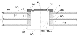
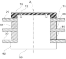
- FIG. 3 is a cross-sectional view showing a magnetic disk and spacers included in the magnetic disk device according to the embodiment
- FIG. 2 is an enlarged cross-sectional view showing a magnetic disk and spacers included in the magnetic disk device according to the embodiment
- FIG. 11 It is a figure which shows that the impact was applied to the magnetic disk with which the magnetic disk apparatus which concerns on embodiment is provided.
- FIG. 11 is an enlarged cross-sectional view showing a magnetic disk and spacers included in a magnetic disk device according to a modification
- FIG. 11 is an enlarged cross-sectional view showing a magnetic disk and spacers included in a magnetic disk device according to a modification;
- a magnetic disk device (HDD: Hard Disk Drive) according to an embodiment of the present invention will be described below with reference to the drawings.
- the magnetic disk device 100 of this embodiment is a box-shaped recording/reproducing device, and as shown in FIGS. a head stack assembly 40; a voice coil motor 50; a ramp load 60; a clamp 70; 2 and 3, the magnetic disk device 100 includes a plurality of spacers 80 arranged between the plurality of magnetic disks 30 and a hub for rotating the plurality of magnetic disks 30 around the rotation axis Z. 90 and.
- the dimensions of the magnetic disk drive 100 are defined by a common standard.
- a 3.5-inch magnetic disk drive with dimensions complying with the SFF-8301 standard is preferably used.
- the height H of the housing 10 is defined as 26.1 mm, the width W as 101.6 mm, and the depth D as 147 mm.
- the housing 10 is generally made of metal, has a cubic box shape with one side open, and includes a base 20, a magnetic disk 30, a head stack assembly 40, a voice coil motor 50, and a lamp.
- a load 60, a clamp 70, and necessary members such as a spindle motor and a circuit board are sealed by a top cover (not shown).
- the base 20 is located at the bottom of the housing 10, and is the part on which the voice coil motor 50, the spindle motor, the circuit board, etc. are mounted.
- the base 20 and the housing 10 are often integrated.
- the magnetic disk 30, as shown in FIGS. 2 and 3, is a disc-shaped medium having a through hole in the center for magnetically recording information, and includes a substrate, an underlayer, a magnetic layer, a protective layer, a lubricating layer, and a magnetic layer. It is composed of layers and rotates about the axis Z of rotation. Perpendicular magnetic recording (PMR) and shingled magnetic recording (SMR) are preferably used as magnetic recording methods. Technologies such as a heat assisted magnetic recording method (HAMR) and a microwave assisted magnetic recording method (MAMR) are being developed in order to achieve even higher capacities.
- the substrate an aluminum alloy substrate or a glass substrate is preferably used as the substrate. Details of the aluminum alloy substrate and the glass substrate will be described later.
- the thickness Td of the magnetic disk 30 is preferably 0.2 mm or more, more preferably 0.35 mm or more.
- the thickness Td of the magnetic disk 30 is 1.75 mm or less, more preferably 0.635 mm or less, even more preferably 0.50 mm or less, particularly preferably 0.48 mm or less, and most preferably 0.48 mm or less. 36 mm or less.
- the outer diameter 2 ⁇ Rd of the magnetic disk 30 is preferably 95 mm or more and 97 mm or less, and the inner diameter is 25 mm.
- the number N of the magnetic disks 30 included in the magnetic disk device 100 of the present embodiment is preferably 8 or more and 16 or less.
- the head stack assembly 40 has an arm 41 and a head section 42 attached to the tip of the arm 41 .
- a laser element is mounted on the head section 42
- a microwave generating element is mounted on the head section 42.
- the voice coil motor 50 is a driving motor that rotates the head stack assembly 40 .
- the ramp load 60 is a part made of resin, and is mounted at a position closest to the magnetic disk 30 on the outer peripheral side of the magnetic disk 30 for the purpose of withdrawing the head portion 42 when the magnetic disk device 100 is not in operation. It is.
- the clamp 70 is made of a non-ferromagnetic metal such as an aluminum alloy, and as shown in FIGS. , a plurality of magnetic disks 30 and spacers 80 are pressed and held against the hub 90 and fixed.
- the surface of the clamp 70 may be coated with Ni--P plating or the like.
- the fastening member 72 is, for example, a screw or a hexalobed (hexagonal star) screw.
- the pitch of the fastening member 72 is coarse, such as 0.4 mm pitch.
- Stainless steel or the like is used as the material of the fastening member 72 .
- the first contact length L1 in the radial direction between the magnetic disk 30 and the protrusion 71 is preferably at least half the second contact length L2 in the radial direction between the magnetic disk 30 and the spacer 80.
- the distance L3 from the center of the fastening member 72 that fixes the clamp 70 to the center of the protrusion 71 is preferably 4.0 to 6.5 mm.
- the hole diameter d1 of the clamp 70 for inserting the fastening member 72 is preferably 2.0 to 3.5 mm.
- the height t1 of the protrusion 71 is preferably 0.1 to 0.5 mm.
- the spacer 80 is a ring-shaped thin plate and is arranged between the multiple magnetic disks 30 .
- the role of the spacer 80 is to secure the intervals between the plurality of magnetic disks 30 and to contact and adhere closely to the magnetic disks 30 , so that the hub 90 is not in direct contact with the hub 90 or the clamp 70 . It is to transmit the rotational driving force.
- the thickness Ts of the spacer 80 the narrower the distance between the magnetic disks 30, the more magnetic disks 30 can be mounted in a limited space. You need a space to let In particular, in the high-capacity technology of HAMR and MAMR described above, when recording by HAMR, it is necessary to mount a laser element in the head section 42, and when recording by MAMR, it is necessary to mount a microwave generation element on the head section 42. Miniaturization of the stack assembly 40 is not easy.
- the distance between the magnetic disks 30, that is, the thickness Ts of the spacer should be at least 1 mm or more, preferably 1.5 mm, more preferably 1.6 mm or more. Moreover, the thickness Ts of the spacer is preferably 1.8 mm or less so that as many magnetic disks 30 as possible can be mounted in the magnetic disk device 100 .
- the shape of the spacer 80 it is desired that the flatness of both surfaces of the spacer 80 is small. Furthermore, it is desirable that the boundary between the surface of the spacer 80 and the inner and outer peripheral end faces (hereinafter referred to as the inner and outer peripheral portions of the spacer) be chamfered for the purpose of deburring. This is because when the magnetic disk 30 and the spacer 80 are laminated, there is a concern that burrs on the inner and outer peripheral portions of the spacer 80 may come into contact with the magnetic disk 30 and cause scratches.
- the material of the spacer 80 is desirably selected from materials that reduce the difference in thermal expansion coefficient between the spacer 80 and the magnetic disk 30 . If the difference between the thermal expansion coefficients of the two is large, positional deviation between the spacer 80 and the surface of the magnetic disk 30 occurs when the environmental temperature during operation of the magnetic disk device 100 changes, causing a read/write error.
- the spacer 80 is preferably made of aluminum.
- the spacer 80 is preferably made of glass, stainless steel, titanium, or the like.
- the spacer 80 preferably has conductivity.
- glass it is desirable that the surface and side surfaces of the spacer 80 made of glass be provided with a metal film such as Ni--P plating.
- Rd is the outer radius of the magnetic disk
- Td is the thickness of the magnetic disk
- Rso is the outer radius of the spacer
- Ts is the thickness of the spacer 80
- T is the stacking height.
- the inner diameter 2Rsi of the magnetic disk 30 and the spacer 80 is, for example, 25 mm.
- the outer diameter 2Rso of the spacer 80 is preferably 32 mm or more and 33 mm or less.
- parts such as the base 20, the circuit board, the spindle motor, the clamp 70, the hub 90, and the top cover are mounted in the space inside the device.
- the stacking height T of the magnetic disk 30 and the spacer 80 is preferably 20 mm or less, more preferably 19 mm or less.
- the lower limit of the thickness Td of the magnetic disk 30 is 0.3 mm
- the lower limit of the thickness Ts of the spacer 80 is 1 mm
- the upper limit of the lamination height T of the magnetic disk 30 and the spacer 80 is 20 mm. Therefore, the upper limit of the number N of the magnetic disks 30 is 16 sheets. Also, in order to increase the capacity of the magnetic disk device 100, the number N of the magnetic disks 30 is preferably eight or more.
- the hub 90 is made of a non-ferromagnetic metal such as an aluminum alloy, and has a shape in which a cylindrical small-diameter portion 91 and a large-diameter portion 92 are connected in the direction of the rotation axis Z. It is rotated by a spindle motor as a central axis.
- the diameter of the small diameter portion 91 is the same as the inner diameter of the magnetic disk 30 and the inner diameter 2Rsi of the spacer 80 . Together with the clamp 70 , the large-diameter portion 92 sandwiches and fixes the magnetic disk 30 and the spacer 80 .
- the magnetic disk 30 is a disc-shaped medium for magnetically recording information, and is composed of a substrate, an underlayer, a magnetic layer, a protective layer, and a lubricating layer.
- An aluminum alloy substrate or a glass substrate is preferably used as the substrate.
- Al alloy substrate As the aluminum alloy substrate, a conventionally used Al--Mg alloy such as JIS5086 alloy is preferably used because of its high strength. Alternatively, an Al—Fe alloy is preferably used because of its high rigidity.
- the Al-Mg alloy contains Mg: 1.0 to 6.5% by mass, Cu: 0.070% by mass or less, Zn: 0.60% by mass or less, Fe: 0.50 % by mass or less, Si: 0.50 mass % or less, Cr: 0.20 mass % or less, Mn: 0.50 mass % or less, Zr: 0.20 mass % or less.
- the balance is an aluminum alloy composed of aluminum, unavoidable impurities, and other trace elements.
- Other trace elements include Be, Sr, etc., and if each of them is 0.1% by mass or less, the effect of the present disclosure is not impaired.
- the Al—Fe alloy contains Fe as an essential element and one or two of Mn and Ni as optional elements, and the total content of these Fe, Mn and Ni is 1.00 to 7.00. 00% by mass, and further, Si: 14.0% by mass or less, Zn: 0.7% by mass or less, Cu: 1.0% by mass or less, Mg: 3.5% by mass or less, Cr: 0 .30% by mass or less and Zr: 0.20% by mass or less, which further contains one or more elements, and the balance is aluminum and inevitable impurities and other trace elements.
- Other trace elements include Be, Sr, etc., and if each of them is 0.1% by mass or less, the effect of the present disclosure is not impaired.
- a semi-continuous casting method is used to produce an ingot, which is hot-rolled and cold-rolled to produce a plate material of a desired thickness.
- a plate material is produced by continuous casting and then cold-rolled to produce a plate material having a desired thickness.
- a heat treatment may be applied to the ingot for the purpose of homogenizing the structure.
- the sheet material may be subjected to heat treatment before cold rolling, during cold rolling, or after cold rolling.
- the plate material produced as described above is stamped with a press to produce a disk-shaped blank having desired inner diameter and outer diameter. After that, in order to reduce the flatness of the blanks, the blanks are laminated together, a load is applied to the laminated blanks, and heat treatment is performed.
- the inner diameter and outer diameter of the blank are cut with a lathe to produce a T-sub having a desired inner diameter, outer diameter and chamfered length. Further, the surfaces of both sides of the blank may be machined to form a T-sub with a desired thickness. Furthermore, the T-sub may be subjected to heat treatment for the purpose of removing processing strain generated inside the material due to cutting.
- the surfaces of both sides of the T-sub are ground by a grinding machine to produce a G-sub of a desired thickness. Further, the G-sub may be subjected to heat treatment for the purpose of removing processing strain generated inside the material due to grinding.
- an M-sub is produced by depositing a desired thickness of plating on all surfaces of the G-sub, including the surface, side surfaces, and chamfered surfaces.
- pretreatment is performed on the G sub for the purpose of improving plating adhesion.
- plating treatment is performed.
- Ni—P electroless plating is preferably used for plating.
- the M-sub may be subjected to heat treatment for the purpose of removing the internal stress of the Ni—P electroless plating.
- the lower limit of the thickness of the aluminum alloy substrate produced by this method is 0.3 mm. This is due to the thickness of a component called a carrier that holds the aluminum alloy substrate during polishing with a polishing machine.
- the thickness of the carrier can be arbitrarily selected as long as it is equal to or greater than the thickness of the aluminum alloy substrate, which is the work piece. From the viewpoint of carrier strength, the thickness of the carrier is preferably 0.3 mm or more. Therefore, the lower limit of the thickness of the aluminum alloy substrate, which is the workpiece, is 0.3 mm.
- a carrier made of a resin such as an aramid resin or an epoxy resin is preferably used. For the purpose of improving strength, a fibrous reinforcing material such as carbon fiber or glass fiber may be contained.
- the magnetic disk 30 is obtained.
- Aluminosilicate glass is preferably used as the glass substrate because of its high hardness.
- the aluminosilicate glass contains SiO 2 : 55 to 70% by mass as a main component, Al 2 O 3 : 25% by mass or less, Li 2 O: 12% by mass or less, and Na 2 O: 12% by mass or less.
- K 2 O 8% by mass or less
- MgO 7% by mass or less
- CaO 10% by mass or less
- ZrO 2 10% by mass or less
- TiO 2 1% by mass or less.
- the balance consists of unavoidable impurities and other trace elements.
- a glass material prepared with a predetermined chemical composition is melted, and the molten mass is press-molded from both sides by a direct press method to produce a glass base plate having a desired thickness.
- the production of the glass base plate is not limited to the direct press method, and may be a float method, a fusion method, a redraw method, or the like.
- this glass base plate is annularly cored, and the inner diameter portion and outer diameter portion are further polished to form an annular glass plate having desired inner diameter dimensions, outer diameter dimensions, and chamfer length.
- annular glass substrate having a desired plate thickness and flatness.
- this annular glass substrate is polished with a polishing machine to produce a substrate having a desired thickness, that is, a glass substrate.
- a chemical strengthening treatment using a sodium nitrate solution, a potassium nitrate solution, or the like may be performed during the polishing process.
- the lower limit of the thickness of the glass substrate produced by this method is 0.3 mm. This is due to the thickness of a part called a carrier that holds the glass substrate during polishing with a polishing machine.
- the thickness of the carrier can be arbitrarily selected as long as it is equal to or greater than the thickness of the glass substrate to be processed. From the viewpoint of carrier strength, the thickness of the carrier is preferably 0.3 mm or more. Therefore, the lower limit of the thickness of the glass substrate, which is the object to be processed, is 0.3 mm.
- a carrier made of a resin such as an aramid resin or an epoxy resin is preferably used.
- a fibrous reinforcing material such as carbon fiber or glass fiber may be contained.
- the magnetic disk 30 When the magnetic disk device 100 receives an external impact, the magnetic disk 30 is bent, and the magnetic disk 30 collides with, for example, the ramp load 60, as shown in FIG.
- the ramp load 60 is made of resin and mounted at a position closest to the magnetic disk 30 on the outer peripheral side of the magnetic disk 30 for the purpose of retracting the head portion 42 when the magnetic disk device 100 is not in operation. is a part of If the magnetic disk 30 collides with the ramp road 60, a part of the ramp road 60 may be chipped to generate foreign matter, or the magnetic disk 30 may be scratched, resulting in failure.
- the magnetic disk 30 rotates at high speed. Its rotation speed is, for example, 7200 rpm.
- turbulence occurs in the gas inside the magnetic disk 30 device, causing the magnetic disk 30 to vibrate. This vibration phenomenon is called fluttering. Vibration of the magnetic disk 30 lowers the positional accuracy of the head unit 42 and causes reading errors.
- a technique of filling the magnetic disk device 100 with helium instead of air is known.
- the impact resistance of the magnetic disk 30 is indicated by the amount of deflection of the magnetic disk 30 when the magnetic disk 30 receives acceleration due to impact.
- the fluttering resistance of the magnetic disk 30 is indicated by the amount of deflection of the magnetic disk 30 when subjected to gas turbulence generated by the high-speed rotation of the magnetic disk 30 .
- the impact resistance and fluttering resistance of the magnetic disk 30 are determined by whether the magnetic disk 30 is flexible or not.
- the clamp 70 is fastened to the hub 90 by a fastening member 72 with a torque of 5 cN ⁇ m or more and 45 cN ⁇ m or less.
- a fastening member 72 As the fastening member 72, a hexalobe screw or the like of T6 to T8 size is preferably used. Note that the diameter of the bolt is M2 or the like.
- the upper limit of torque for fastening is 45 cN ⁇ m, preferably 40 cN ⁇ m, more preferably 35 cN ⁇ m.
- the impact resistance of the magnetic disk device 100 can be improved by setting the upper limit values of the torque at the time of fastening to these values.
- these values are the upper limit values of the torque during fastening, so that it is possible to prevent a gap from forming in a portion of the contact portion between the magnetic disk 30 and the spacer 80 . Since there is no gap in a part of the contact portion between the magnetic disk 30 and the spacer 80, even if the magnetic disk device 100 is subjected to an external impact, the magnetic disk 30 is prevented from being deformed, and the magnetic disk device 100 is durable. Excellent impact resistance.
- the lower limit of the tightening torque is 5 cN ⁇ m, preferably 20 cN ⁇ m, more preferably 25 cN ⁇ m. The magnetic disk 30 and the spacer 80 can be sufficiently fastened by setting the fastening torque to these values. Further, if the lower limit of the tightening torque is less than 5 cN ⁇ m, the tightening member 72 may loosen.
- the first radial contact length L1 between the magnetic disk 30 and the clamp 70 is preferably half or more of the second radial contact length L2 between the magnetic disk 30 and the spacer 80 .
- Impact resistance can be improved by setting the ratio of the first contact length L1/the second contact length L2 to 1/2 or more. Since the first contact length L1/second contact length L2 is 1/2 or more, the contact portion between the magnetic disk 30 and the clamp 70 is large, and the gap between the magnetic disk 30 and the clamp 70 is reduced. can. Since the gap is small, the magnetic disk 30 can be prevented from being deformed even if the magnetic disk device 100 is subjected to an external shock, and the magnetic disk device 100 is excellent in shock resistance.
- the first contact length L1/second contact length L2 is preferably 1/2 or more, more preferably 0.9 or more. From the viewpoint of impact resistance, it is preferable that the first contact length L1/second contact length L2 be close to 1.0. It is preferable to set the upper limit to about 0.95.
- the magnetic disk 30 and the spacer 80 are arranged on the hub 90 in the arranging step, and the clamp 70 is clamped with a torque of 5 cNm or more and 45 cNm or less in the fastening step. are fastened to the hub 90 with the fastening member 72 .
- the magnetic disks 30 and the spacers 80 are alternately stacked and arranged on the hub 90 .
- the clamp 70 is placed on the hub 90 on which the magnetic disk 30 and the spacer 80 are arranged. Magnetic disk 30 and spacer 80 are thereby fixed to hub 90 .
- the upper limit of the torque when fastening the clamp 70 with the fastening member 72 is 45 cN ⁇ m, preferably 40 cN ⁇ m, more preferably 35 cN ⁇ m, as described above.
- the lower limit of torque is 5 cN ⁇ m, preferably 20 cN ⁇ m, more preferably 25 cN ⁇ m.
- six fastening members 72 are used for fastening, but it is preferable that the fastening torque is the same.
- the tightening torque can be adjusted, for example, with a Kanon idling torque driver manufactured by Nakamura Seisakusho.
- the fastening torque can be measured using, for example, a torque driver manufactured by Tohnichi Seisakusho.
- the magnetic disk device 100 of the present embodiment by appropriately adjusting the torque when tightening the clamp 70, the impact resistance can be improved without reducing the recording area. Therefore, it is possible to provide a 3.5-inch magnetic disk drive equipped with a magnetic disk made of an aluminum alloy substrate and a glass substrate having excellent shock resistance and high data capacity.
- the first contact length L1 in the radial direction between the magnetic disk 30 and the clamp 70 is half or more of the second contact length L2 in the radial direction between the magnetic disk 30 and the spacer 80.
- the magnetic disk device 100 can improve impact resistance without reducing the recording area. By installing the magnetic disk device 100 in the data center, it is possible to contribute to increasing the capacity of the data center.
- the recording area is reduced by appropriately adjusting the torque when tightening the clamp 70, or by making the first contact length L1 half or more of the second contact length L2.
- the idea of the present embodiment that the impact resistance can be improved without the need to reduce the impact can be applied not only to the 3.5-inch magnetic disk device 100 but also to magnetic disk devices 100 of any size.
- the type of the magnetic disk 30 is not limited to the magnetic disk 30 made of an aluminum alloy substrate and a glass substrate, and can be applied to all kinds of magnetic disks 30 .
- FIG. 5 An example in which the spacers 80 are arranged between the magnetic disks 30 without being overlapped has been described.
- a plurality of spacers 80 may be laminated. Normally, one spacer 80 is inserted between the magnetic disks 30, but the impact resistance can be improved by stacking two or more spacers.
- the number of spacers 80 should be as large as possible. However, if the number of spacers 80 is too large, the number of magnetic disks 30 to be mounted is reduced, so the upper limit is three. Further, as shown in FIG. 6, if the number of spacers 80 is two or more, the number of magnetic disks 30 to be mounted is reduced.
- the magnetic disk device 100 is a 3.5-inch magnetic disk device
- the magnetic disk device 100 may be a device other than a 3.5-inch device. It may be a 5-inch magnetic disk device.
- a plated aluminum alloy substrate having the composition shown in Table 1 and a glass substrate having the composition shown in Table 2 were produced as the magnetic disk substrate 31 .
- the substrate size was set to an inner diameter of 25 mm, an outer diameter of 97 mm, and a plate thickness of 0.50 mm.
- the spacer 80 was made of aluminum and had an inner diameter of 25 mm, an outer diameter of 32 mm, and a thickness of 1.7 mm.
- the clamp 70 has a distance L3 of 5 mm from the center of the fastening member 72 shown in FIG. A clamp was used in which the height t1 of the protrusion 71 shown was set to 0.2 mm.
- a T6 size hexalobe screw with a bolt diameter of M2 was used as the fastening member 72.
- the magnetic disk substrate 31 was fixed to the hub 90 with spacers 80 and clamps 70, and they were installed in an impact test apparatus.
- Tightening torque when fixing the magnetic disk substrates 31 of Examples 1 to 9 and Comparative Examples 1 to 5 is shown in Table 1
- fastening torque when fixing the magnetic disk substrates 31 of Examples 10 to 11 and Comparative Example 6. are shown in Table 2.
- the fastening torque was adjusted with a Kanon idling torque driver manufactured by Nakamura Seisakusho. Torque was measured using a torque driver manufactured by Tohnichi Seisakusho.
- the amount of deflection due to impact between the outer peripheral position of the magnetic disk substrate 31 (distance r1 from the substrate center: 44.2 mm) and the inner peripheral position of the magnetic disk substrate 31 (distance r2 from the substrate center: 23 mm) was measured by a capacitance type distance sensor by applying an impact with an acceleration of 55 to 60 G and an action time of 2.7 to 3.0 ms.
- Examples 1 and 2 are Comparative Example 1
- Examples 3 and 4 are Comparative Example 2
- Examples 5 and 6 are Comparative Example 3
- Examples 7 and 9 are Comparative Example 4, and
- Examples 10 and 11 are Comparative Example 6.
- a relative value of the maximum amount of deflection was obtained based on the results.
- the relative value of the maximum deflection amount of Comparative Example 5 was obtained by setting the maximum deflection amount of Comparative Example 4 as 100%.
- Comparative Example 5 since the fastening torque was 60 cN ⁇ m, the relative value of the maximum deflection amount was larger than that in Comparative Example 4, in which the fastening torque was 50 cN ⁇ m.
- Tables 1 and 2 show the relative values of the maximum deflection amounts obtained as described above.
- the fastening torques of Examples 1 to 11 are 10 to 40 cN m, and the relative values of the maximum deflection amounts of Examples 1 to 11 are in the corresponding Comparative Examples 1 to 4 and 6. less than 100%. As described above, it was found that when the engagement torque is 10 to 40 cN ⁇ m, the relative value of the maximum deflection amount is smaller than when the engagement torque is 50 cN ⁇ m.
- an aluminum alloy substrate having the composition shown in Table 3 was produced as the magnetic disk substrate 31, as the magnetic disk substrate 31, an aluminum alloy substrate having the composition shown in Table 3 was produced.
- the substrate size was 25 mm in inner diameter, 97 mm in outer diameter, and 0.35 mm in thickness.
- the spacers 80 of Examples 12 and 13 and Comparative Example 7 were made of aluminum with an inner diameter of 25 mm, an outer diameter of 32 mm, and a thickness of 1.7 mm.
- the spacers 80 of Examples 16 to 18 and Comparative Examples 9 and 10 are made of aluminum with an inner diameter of 25 mm, an outer diameter of 33 mm, and a thickness of 1.8 mm. used.
- the distance L3 from the center of the fastening member 72 to the center of the protrusion 71 is 5 mm
- the hole diameter d1 of the clamp 70 for inserting the fastening member 72 is 2 mm
- the protrusion 71 is A height t1 of 0.2 mm was used.
- the fastening member 72 has a bolt diameter of M2 and uses a T6 size hexalobe screw.
- the magnetic disk substrate 31 was fixed to the hub 90 with spacers 80 and clamps 70, and they were installed in an impact test apparatus.
- Table 3 shows the fastening torque when fixing the magnetic disk substrates 31 of Examples 12-18 and Comparative Examples 7-10.
- the fastening torque was adjusted with a Kanon idling torque driver manufactured by Nakamura Seisakusho. Moreover, when measuring the torque, it was implemented with a torque driver manufactured by Tohnichi Seisakusho.
- the amount of deflection due to impact between the outer peripheral position of the magnetic disk substrate 31 (distance r1 from the substrate center: 44.2 mm) and the inner peripheral position of the magnetic disk substrate 31 (distance r2 from the substrate center: 23 mm) was measured by a capacitance type distance sensor by applying an impact with an acceleration of 31 to 33 G and an action time of 3.6 to 3.85 ms.
- Relative values of the maximum amount of deflection were determined based on Comparative Example 7 for Examples 12 and 13, Comparative Example 8 for Examples 14 and 15, and Comparative Example 9 for Examples 16-18.
- the relative value of the maximum deflection amount of Comparative Example 10 was obtained by setting the maximum deflection amount of Comparative Example 9 as 100%.
- Comparative Example 10 since the fastening torque was 60 cN ⁇ m, the relative value of the maximum deflection amount was larger than that in Comparative Example 9, in which the fastening torque was 50 cN ⁇ m. As described above, it was found that when the engagement torque is 10 to 40 cN ⁇ m, the relative value of the maximum deflection amount is smaller than when the engagement torque is 50 cN ⁇ m.
- the magnetic disk substrate 31 an aluminum alloy substrate having the composition shown in Table 4 and a glass substrate having the composition shown in Table 5 were produced.
- the aluminum alloy substrate had an inner diameter of 25 mm, an outer diameter of 95 mm and a thickness of 0.635 mm
- the glass substrate had an inner diameter of 25 mm, an outer diameter of 97 mm and a thickness of 0.5 mm.
- the spacer 80 was made of aluminum and had an inner diameter of 25 mm, an outer diameter of 32 mm, and a thickness of 1.6 mm.
- the distance L3 from the center of the fastening member 72 to the center of the protrusion 71 is 5 mm
- the hole diameter d1 of the clamp 70 for inserting the fastening member 72 is 2 mm
- the protrusion 71 is A height t1 of 0.2 mm was used.
- the fastening member 72 has a bolt diameter of M2 and uses a T6 size hexalobe screw.
- the magnetic disk substrate 31 was fixed to the hub 90 with spacers 80 and clamps 70, and they were installed in an impact test apparatus.
- Table 4 shows the tightening torque when fixing the magnetic disk substrates 31 of Examples 19 and 20 and Comparative Example 11, and Table 4 shows the tightening torque when fixing the magnetic disk substrates 31 of Examples 21 and 22 and Comparative Example 12. 5.
- the fastening torque was adjusted with a Kanon idling torque driver manufactured by Nakamura Seisakusho. Moreover, when measuring the torque, it was implemented with a torque driver manufactured by Tohnichi Seisakusho.
- the amount of deflection due to impact between the outer peripheral position of the magnetic disk substrate 31 (distance r1 from the substrate center: 44.2 mm) and the inner peripheral position of the magnetic disk substrate 31 (distance r2 from the substrate center: 23 mm) was measured by a capacitive distance sensor by applying an impact with an acceleration of 51 to 56 G and an action time of 2.7 to 3.0 ms.
- the maximum absolute value of ”/“acceleration”, hereinafter referred to as the maximum deflection amount) was calculated. Measurement was performed once for each sample. After that, relative values of the maximum deflection amounts of each of the fastening torques of Examples 19 to 22 were obtained, with the maximum deflection amounts of Comparative Examples 11 and 12 having fastening torques of 50 cN ⁇ m being taken as 100%. The relative value of the maximum amount of deflection was determined based on Comparative Example 11 for Examples 19 and 20 and Comparative Example 12 for Examples 21 and 22. As described above, it was found that when the engagement torque is 30 to 40 cN ⁇ m, the relative value of the maximum deflection amount is smaller than when the engagement torque is 50 cN ⁇ m.
- the maximum amount of deflection of the magnetic disk substrate 31 due to the impact is large, it will strongly collide with parts in the magnetic disk device, for example, the ramp road, and a part of the ramp road will be chipped to generate foreign matter, or the magnetic disk will be scratched. may stick and cause malfunction.
- Examples 23-25 are identical in composition to the corresponding Comparative Examples 13-15.
- Tables 6 and 7 show the relative values of the maximum deflection amounts obtained as described above. Referring to Tables 6 and 7, the relative values of maximum deflection for Examples 23-25 are less than 100% relative to the corresponding Comparative Examples 13-15.
- the relative values of the maximum deflection amounts of Examples 23 to 25, in which L1/L2 is 1.00, are smaller than the relative values of the maximum deflection amounts in Comparative Examples 13 to 15, in which L1/L2 is 0.06.
- An impact resistance of ⁇ 25 was found to be good.
- the magnetic disk substrate 31 was fixed to the hub 90 with the spacers 80 and the clamps 70 by changing the number of the spacers 80 by setting the tightening torque to 40 cN ⁇ m and L1/L2 to 1.00. Then, they were installed in the same impact test apparatus as above, and the same test was performed. After that, relative values of the maximum deflection amounts of Examples 26 to 28, in which two spacers 80 were provided, were obtained, with the maximum deflection amounts in Comparative Examples 16 to 18, in which one spacer 80 was provided, as 100%. The relative value of the maximum deflection amount was determined based on Comparative Example 16 for Example 26, Comparative Example 17 for Example 27, and Comparative Example 18 for Example 28.
- Examples 26-28 are identical in composition to the corresponding Comparative Examples 16-18.
- Tables 8 and 9 show the relative values of the maximum deflection amounts obtained as described above. Referring to Tables 8 and 9, the relative values of maximum deflection for Examples 26-28 with two spacers 80 are 100% higher than the corresponding Comparative Examples 16-18 with one spacer 80. It was found that the impact resistance of Examples 26-28 was good.
- the thickness of the magnetic disk substrate 31 can be kept as it is and the impact resistance can be improved.
- the ratio of the first contact length L1 and the second contact length L2 is improved while keeping the fastening torque and the thickness of the magnetic disk substrate 31 as they are. be able to.
- the impact resistance can be improved while keeping the fastening torque, L1/L2 and the thickness of the magnetic disk substrate 31 as they are.
- the magnetic disk substrate 31 is different from the magnetic disk 30 in that it does not include a magnetic layer or the like, but is considered to be equivalent to the magnetic disk 30 in terms of impact resistance and the like. Therefore, by setting the fastening torque and L1/L2 to the values described above, or by setting the number of spacers 80 to two, it is possible to provide a magnetic disk drive having excellent shock resistance and high data capacity. rice field.
Landscapes
- Holding Or Fastening Of Disk On Rotational Shaft (AREA)
- Magnetic Record Carriers (AREA)
Priority Applications (3)
| Application Number | Priority Date | Filing Date | Title |
|---|---|---|---|
| CN202280022510.1A CN117015825A (zh) | 2021-03-19 | 2022-02-28 | 磁盘装置及制造磁盘装置的方法 |
| US18/547,728 US12394440B2 (en) | 2021-03-19 | 2022-02-28 | Magnetic disk device and method for manufacturing magnetic disk device |
| JP2023506930A JP7633378B2 (ja) | 2021-03-19 | 2022-02-28 | 磁気ディスク装置および磁気ディスク装置を製造する方法 |
Applications Claiming Priority (2)
| Application Number | Priority Date | Filing Date | Title |
|---|---|---|---|
| JP2021-046121 | 2021-03-19 | ||
| JP2021046121 | 2021-03-19 |
Publications (1)
| Publication Number | Publication Date |
|---|---|
| WO2022196314A1 true WO2022196314A1 (ja) | 2022-09-22 |
Family
ID=83321418
Family Applications (1)
| Application Number | Title | Priority Date | Filing Date |
|---|---|---|---|
| PCT/JP2022/008147 Ceased WO2022196314A1 (ja) | 2021-03-19 | 2022-02-28 | 磁気ディスク装置および磁気ディスク装置を製造する方法 |
Country Status (4)
| Country | Link |
|---|---|
| US (1) | US12394440B2 (https=) |
| JP (1) | JP7633378B2 (https=) |
| CN (1) | CN117015825A (https=) |
| WO (1) | WO2022196314A1 (https=) |
Citations (5)
| Publication number | Priority date | Publication date | Assignee | Title |
|---|---|---|---|---|
| JP2007185035A (ja) * | 2006-01-06 | 2007-07-19 | Victor Co Of Japan Ltd | ディスク駆動用モータ |
| JP2008276942A (ja) * | 2008-08-19 | 2008-11-13 | Fujitsu Ltd | 密閉型記録ディスク駆動装置並びに記録ディスク駆動装置向けクランプおよびスペーサおよびスピンドルモータ |
| WO2008139537A1 (ja) * | 2007-04-27 | 2008-11-20 | Fujitsu Limited | 記憶媒体駆動装置 |
| JP2010211909A (ja) * | 2009-03-11 | 2010-09-24 | Hitachi Global Storage Technologies Netherlands Bv | ディスクスタックアセンブリ |
| WO2020111282A1 (ja) * | 2018-11-30 | 2020-06-04 | Hoya株式会社 | ガラス板の製造方法、ガラス板の面取り方法、および磁気ディスクの製造方法 |
Family Cites Families (19)
| Publication number | Priority date | Publication date | Assignee | Title |
|---|---|---|---|---|
| JPS6368187U (https=) * | 1986-10-22 | 1988-05-09 | ||
| JP2755156B2 (ja) * | 1994-01-31 | 1998-05-20 | 日本電気株式会社 | 磁気ディスク装置 |
| US5982581A (en) * | 1994-04-04 | 1999-11-09 | Seagate Technology, Inc. | Disc clamp with head clearance |
| US5659443A (en) * | 1995-12-01 | 1997-08-19 | International Business Machines Corporation | Split band retainer for radially clamping a disk to a hub in a disk drive |
| KR100251949B1 (ko) * | 1996-03-30 | 2000-04-15 | 윤종용 | 하드디스크 드라이브의 디스크 클램핑 장치 |
| JP2000076762A (ja) | 1998-08-26 | 2000-03-14 | Mitsubishi Chemicals Corp | 光記録媒体の装着装置 |
| US6255750B1 (en) * | 1999-04-21 | 2001-07-03 | Seagate Technology Llc | Apparatus and method for reducing disc flutter and disc vibration effects in a disc drive |
| JP2001331995A (ja) | 2000-05-17 | 2001-11-30 | Matsushita Electric Ind Co Ltd | 磁気ディスク装置 |
| JP4031953B2 (ja) * | 2001-06-11 | 2008-01-09 | 株式会社日立グローバルストレージテクノロジーズ | 磁気ディスク装置 |
| US7209320B1 (en) * | 2004-01-16 | 2007-04-24 | Excelstor Technology, Inc. | Offset angle disc clamp |
| JP2009054254A (ja) | 2007-08-28 | 2009-03-12 | Konica Minolta Opto Inc | 磁気記録媒体用基板及び磁気記録装置 |
| JP5227711B2 (ja) | 2007-09-28 | 2013-07-03 | Hoya株式会社 | 磁気ディスク用ガラス基板及びその製造方法 |
| KR20100104168A (ko) * | 2009-03-17 | 2010-09-29 | 삼성전자주식회사 | 하드디스크 드라이브의 fod 전압 제어 방법 |
| JPWO2011096310A1 (ja) | 2010-02-03 | 2013-06-10 | コニカミノルタアドバンストレイヤー株式会社 | 情報記録媒体用ガラス基板、情報記録媒体用ガラス基板の製造方法及び情報記録媒体 |
| JP2013218752A (ja) | 2012-04-05 | 2013-10-24 | Samsung Electromechanics Japan Advanced Technology Co Ltd | ディスク駆動装置 |
| WO2017188320A1 (ja) | 2016-04-27 | 2017-11-02 | 株式会社Uacj | 磁気ディスク用基板 |
| CN109563572B (zh) | 2016-08-01 | 2021-03-23 | 株式会社Uacj | 磁盘基板用铝合金板及其制造方法、磁盘 |
| US12051442B2 (en) * | 2020-09-30 | 2024-07-30 | Hoya Corporation | Hard disk drive spacer having chamfered surface and main surface with inclined region |
| US12555601B2 (en) * | 2021-10-01 | 2026-02-17 | Western Digital Technologies, Inc. | Magnetic recording disk with high internal stress to reduce disk deflections from shock forces and methods for use with the disk |
-
2022
- 2022-02-28 WO PCT/JP2022/008147 patent/WO2022196314A1/ja not_active Ceased
- 2022-02-28 JP JP2023506930A patent/JP7633378B2/ja active Active
- 2022-02-28 CN CN202280022510.1A patent/CN117015825A/zh active Pending
- 2022-02-28 US US18/547,728 patent/US12394440B2/en active Active
Patent Citations (5)
| Publication number | Priority date | Publication date | Assignee | Title |
|---|---|---|---|---|
| JP2007185035A (ja) * | 2006-01-06 | 2007-07-19 | Victor Co Of Japan Ltd | ディスク駆動用モータ |
| WO2008139537A1 (ja) * | 2007-04-27 | 2008-11-20 | Fujitsu Limited | 記憶媒体駆動装置 |
| JP2008276942A (ja) * | 2008-08-19 | 2008-11-13 | Fujitsu Ltd | 密閉型記録ディスク駆動装置並びに記録ディスク駆動装置向けクランプおよびスペーサおよびスピンドルモータ |
| JP2010211909A (ja) * | 2009-03-11 | 2010-09-24 | Hitachi Global Storage Technologies Netherlands Bv | ディスクスタックアセンブリ |
| WO2020111282A1 (ja) * | 2018-11-30 | 2020-06-04 | Hoya株式会社 | ガラス板の製造方法、ガラス板の面取り方法、および磁気ディスクの製造方法 |
Also Published As
| Publication number | Publication date |
|---|---|
| CN117015825A (zh) | 2023-11-07 |
| US20240233766A9 (en) | 2024-07-11 |
| US20240135971A1 (en) | 2024-04-25 |
| JPWO2022196314A1 (https=) | 2022-09-22 |
| JP7633378B2 (ja) | 2025-02-19 |
| US12394440B2 (en) | 2025-08-19 |
Similar Documents
| Publication | Publication Date | Title |
|---|---|---|
| US12020735B2 (en) | Substrate for magnetic disk and magnetic disk | |
| US6678120B2 (en) | Multiple-modular actuators having a common axis of rotation | |
| CN111383667A (zh) | 磁记录介质用基板、磁记录介质、硬盘驱动器 | |
| CN110431627A (zh) | 磁盘用基板和磁盘 | |
| CN111383668A (zh) | 磁记录介质用基板、磁记录介质、硬盘驱动器 | |
| JPH04123314A (ja) | ディスク型記録媒体および記憶装置 | |
| WO2022196314A1 (ja) | 磁気ディスク装置および磁気ディスク装置を製造する方法 | |
| JP7069279B1 (ja) | 磁気ディスク装置 | |
| JP7490615B2 (ja) | ディスク装置およびディスク装置の製造方法 | |
| JP7633370B2 (ja) | 磁気ディスク装置 | |
| US7933093B2 (en) | Spindle motor, and recording and reproducing apparatus equipped with the same | |
| JP5486039B2 (ja) | 磁気ディスク装置に用いるスペーサーおよび磁気ディスク装置 | |
| WO2011162279A1 (ja) | 磁気記録媒体およびその製造方法 | |
| JP2014067475A (ja) | ハードディスクドライブ用ベースプレート及びその製造方法、ハードディスクドライブ | |
| JP3128069U (ja) | 磁気記録媒体用の基板とそれを用いた磁気記録媒体 | |
| JP2009515286A (ja) | 読み出し/書き込み時の振動を抑制する光ディスク及びその製造方法 | |
| CN1967683B (zh) | 抑制读写时振动的光盘及其制造方法 | |
| WO2025206376A1 (ja) | 磁気記録装置、及び積層構造体 | |
| JPH10208241A (ja) | 磁気ディスク及びその製造方法 | |
| JP2004280961A (ja) | ディスク基板及びその製造方法、磁気ディスク | |
| JPH033106A (ja) | 磁気ヘッド研磨用ディスク |
Legal Events
| Date | Code | Title | Description |
|---|---|---|---|
| 121 | Ep: the epo has been informed by wipo that ep was designated in this application |
Ref document number: 22771069 Country of ref document: EP Kind code of ref document: A1 |
|
| WWE | Wipo information: entry into national phase |
Ref document number: 2023506930 Country of ref document: JP |
|
| WWE | Wipo information: entry into national phase |
Ref document number: 18547728 Country of ref document: US |
|
| WWE | Wipo information: entry into national phase |
Ref document number: 202280022510.1 Country of ref document: CN |
|
| NENP | Non-entry into the national phase |
Ref country code: DE |
|
| 122 | Ep: pct application non-entry in european phase |
Ref document number: 22771069 Country of ref document: EP Kind code of ref document: A1 |
|
| WWG | Wipo information: grant in national office |
Ref document number: 18547728 Country of ref document: US |