WO2022196305A1 - 動力伝達装置 - Google Patents
動力伝達装置 Download PDFInfo
- Publication number
- WO2022196305A1 WO2022196305A1 PCT/JP2022/008044 JP2022008044W WO2022196305A1 WO 2022196305 A1 WO2022196305 A1 WO 2022196305A1 JP 2022008044 W JP2022008044 W JP 2022008044W WO 2022196305 A1 WO2022196305 A1 WO 2022196305A1
- Authority
- WO
- WIPO (PCT)
- Prior art keywords
- oil
- case member
- rotation axis
- shaft
- gear
- Prior art date
- Legal status (The legal status is an assumption and is not a legal conclusion. Google has not performed a legal analysis and makes no representation as to the accuracy of the status listed.)
- Ceased
Links
Images


Classifications
-
- F—MECHANICAL ENGINEERING; LIGHTING; HEATING; WEAPONS; BLASTING
- F16—ENGINEERING ELEMENTS AND UNITS; GENERAL MEASURES FOR PRODUCING AND MAINTAINING EFFECTIVE FUNCTIONING OF MACHINES OR INSTALLATIONS; THERMAL INSULATION IN GENERAL
- F16H—GEARING
- F16H57/00—General details of gearing
- F16H57/02—Gearboxes; Mounting gearing therein
- F16H57/021—Shaft support structures, e.g. partition walls, bearing eyes, casing walls or covers with bearings
-
- B—PERFORMING OPERATIONS; TRANSPORTING
- B60—VEHICLES IN GENERAL
- B60K—ARRANGEMENT OR MOUNTING OF PROPULSION UNITS OR OF TRANSMISSIONS IN VEHICLES; ARRANGEMENT OR MOUNTING OF PLURAL DIVERSE PRIME-MOVERS IN VEHICLES; AUXILIARY DRIVES FOR VEHICLES; INSTRUMENTATION OR DASHBOARDS FOR VEHICLES; ARRANGEMENTS IN CONNECTION WITH COOLING, AIR INTAKE, GAS EXHAUST OR FUEL SUPPLY OF PROPULSION UNITS IN VEHICLES
- B60K1/00—Arrangement or mounting of electrical propulsion units
-
- F—MECHANICAL ENGINEERING; LIGHTING; HEATING; WEAPONS; BLASTING
- F16—ENGINEERING ELEMENTS AND UNITS; GENERAL MEASURES FOR PRODUCING AND MAINTAINING EFFECTIVE FUNCTIONING OF MACHINES OR INSTALLATIONS; THERMAL INSULATION IN GENERAL
- F16H—GEARING
- F16H48/00—Differential gearings
- F16H48/06—Differential gearings with gears having orbital motion
- F16H48/08—Differential gearings with gears having orbital motion comprising bevel gears
-
- F—MECHANICAL ENGINEERING; LIGHTING; HEATING; WEAPONS; BLASTING
- F16—ENGINEERING ELEMENTS AND UNITS; GENERAL MEASURES FOR PRODUCING AND MAINTAINING EFFECTIVE FUNCTIONING OF MACHINES OR INSTALLATIONS; THERMAL INSULATION IN GENERAL
- F16H—GEARING
- F16H48/00—Differential gearings
- F16H48/38—Constructional details
- F16H48/40—Constructional details characterised by features of the rotating cases
-
- B—PERFORMING OPERATIONS; TRANSPORTING
- B60—VEHICLES IN GENERAL
- B60K—ARRANGEMENT OR MOUNTING OF PROPULSION UNITS OR OF TRANSMISSIONS IN VEHICLES; ARRANGEMENT OR MOUNTING OF PLURAL DIVERSE PRIME-MOVERS IN VEHICLES; AUXILIARY DRIVES FOR VEHICLES; INSTRUMENTATION OR DASHBOARDS FOR VEHICLES; ARRANGEMENTS IN CONNECTION WITH COOLING, AIR INTAKE, GAS EXHAUST OR FUEL SUPPLY OF PROPULSION UNITS IN VEHICLES
- B60K1/00—Arrangement or mounting of electrical propulsion units
- B60K2001/001—Arrangement or mounting of electrical propulsion units one motor mounted on a propulsion axle for rotating right and left wheels of this axle
-
- B—PERFORMING OPERATIONS; TRANSPORTING
- B60—VEHICLES IN GENERAL
- B60Y—INDEXING SCHEME RELATING TO ASPECTS CROSS-CUTTING VEHICLE TECHNOLOGY
- B60Y2306/00—Other features of vehicle sub-units
- B60Y2306/03—Lubrication
-
- B—PERFORMING OPERATIONS; TRANSPORTING
- B60—VEHICLES IN GENERAL
- B60Y—INDEXING SCHEME RELATING TO ASPECTS CROSS-CUTTING VEHICLE TECHNOLOGY
- B60Y2400/00—Special features of vehicle units
- B60Y2400/70—Gearings
- B60Y2400/73—Planetary gearings
-
- B—PERFORMING OPERATIONS; TRANSPORTING
- B60—VEHICLES IN GENERAL
- B60Y—INDEXING SCHEME RELATING TO ASPECTS CROSS-CUTTING VEHICLE TECHNOLOGY
- B60Y2410/00—Constructional features of vehicle sub-units
- B60Y2410/10—Housings
-
- B—PERFORMING OPERATIONS; TRANSPORTING
- B60—VEHICLES IN GENERAL
- B60Y—INDEXING SCHEME RELATING TO ASPECTS CROSS-CUTTING VEHICLE TECHNOLOGY
- B60Y2410/00—Constructional features of vehicle sub-units
- B60Y2410/102—Shaft arrangements; Shaft supports, e.g. bearings
-
- F—MECHANICAL ENGINEERING; LIGHTING; HEATING; WEAPONS; BLASTING
- F16—ENGINEERING ELEMENTS AND UNITS; GENERAL MEASURES FOR PRODUCING AND MAINTAINING EFFECTIVE FUNCTIONING OF MACHINES OR INSTALLATIONS; THERMAL INSULATION IN GENERAL
- F16H—GEARING
- F16H48/00—Differential gearings
- F16H48/38—Constructional details
- F16H2048/382—Methods for manufacturing differential gearings
-
- F—MECHANICAL ENGINEERING; LIGHTING; HEATING; WEAPONS; BLASTING
- F16—ENGINEERING ELEMENTS AND UNITS; GENERAL MEASURES FOR PRODUCING AND MAINTAINING EFFECTIVE FUNCTIONING OF MACHINES OR INSTALLATIONS; THERMAL INSULATION IN GENERAL
- F16H—GEARING
- F16H57/00—General details of gearing
- F16H57/02—Gearboxes; Mounting gearing therein
- F16H2057/02008—Gearboxes; Mounting gearing therein characterised by specific dividing lines or planes of the gear case
-
- F—MECHANICAL ENGINEERING; LIGHTING; HEATING; WEAPONS; BLASTING
- F16—ENGINEERING ELEMENTS AND UNITS; GENERAL MEASURES FOR PRODUCING AND MAINTAINING EFFECTIVE FUNCTIONING OF MACHINES OR INSTALLATIONS; THERMAL INSULATION IN GENERAL
- F16H—GEARING
- F16H57/00—General details of gearing
- F16H57/0018—Shaft assemblies for gearings
- F16H57/0025—Shaft assemblies for gearings with gearing elements rigidly connected to a shaft, e.g. securing gears or pulleys by specially adapted splines, keys or methods
-
- F—MECHANICAL ENGINEERING; LIGHTING; HEATING; WEAPONS; BLASTING
- F16—ENGINEERING ELEMENTS AND UNITS; GENERAL MEASURES FOR PRODUCING AND MAINTAINING EFFECTIVE FUNCTIONING OF MACHINES OR INSTALLATIONS; THERMAL INSULATION IN GENERAL
- F16H—GEARING
- F16H57/00—General details of gearing
- F16H57/02—Gearboxes; Mounting gearing therein
- F16H57/037—Gearboxes for accommodating differential gearings
-
- F—MECHANICAL ENGINEERING; LIGHTING; HEATING; WEAPONS; BLASTING
- F16—ENGINEERING ELEMENTS AND UNITS; GENERAL MEASURES FOR PRODUCING AND MAINTAINING EFFECTIVE FUNCTIONING OF MACHINES OR INSTALLATIONS; THERMAL INSULATION IN GENERAL
- F16H—GEARING
- F16H57/00—General details of gearing
- F16H57/04—Features relating to lubrication or cooling or heating
- F16H57/042—Guidance of lubricant
- F16H57/0421—Guidance of lubricant on or within the casing, e.g. shields or baffles for collecting lubricant, tubes, pipes, grooves, channels or the like
- F16H57/0424—Lubricant guiding means in the wall of or integrated with the casing, e.g. grooves, channels, holes
-
- F—MECHANICAL ENGINEERING; LIGHTING; HEATING; WEAPONS; BLASTING
- F16—ENGINEERING ELEMENTS AND UNITS; GENERAL MEASURES FOR PRODUCING AND MAINTAINING EFFECTIVE FUNCTIONING OF MACHINES OR INSTALLATIONS; THERMAL INSULATION IN GENERAL
- F16H—GEARING
- F16H57/00—General details of gearing
- F16H57/04—Features relating to lubrication or cooling or heating
- F16H57/042—Guidance of lubricant
- F16H57/043—Guidance of lubricant within rotary parts, e.g. axial channels or radial openings in shafts
-
- F—MECHANICAL ENGINEERING; LIGHTING; HEATING; WEAPONS; BLASTING
- F16—ENGINEERING ELEMENTS AND UNITS; GENERAL MEASURES FOR PRODUCING AND MAINTAINING EFFECTIVE FUNCTIONING OF MACHINES OR INSTALLATIONS; THERMAL INSULATION IN GENERAL
- F16H—GEARING
- F16H57/00—General details of gearing
- F16H57/04—Features relating to lubrication or cooling or heating
- F16H57/045—Lubricant storage reservoirs, e.g. reservoirs in addition to a gear sump for collecting lubricant in the upper part of a gear case
-
- F—MECHANICAL ENGINEERING; LIGHTING; HEATING; WEAPONS; BLASTING
- F16—ENGINEERING ELEMENTS AND UNITS; GENERAL MEASURES FOR PRODUCING AND MAINTAINING EFFECTIVE FUNCTIONING OF MACHINES OR INSTALLATIONS; THERMAL INSULATION IN GENERAL
- F16H—GEARING
- F16H57/00—General details of gearing
- F16H57/04—Features relating to lubrication or cooling or heating
- F16H57/0457—Splash lubrication
-
- F—MECHANICAL ENGINEERING; LIGHTING; HEATING; WEAPONS; BLASTING
- F16—ENGINEERING ELEMENTS AND UNITS; GENERAL MEASURES FOR PRODUCING AND MAINTAINING EFFECTIVE FUNCTIONING OF MACHINES OR INSTALLATIONS; THERMAL INSULATION IN GENERAL
- F16H—GEARING
- F16H57/00—General details of gearing
- F16H57/04—Features relating to lubrication or cooling or heating
- F16H57/0467—Elements of gearings to be lubricated, cooled or heated
- F16H57/0469—Bearings or seals
- F16H57/0471—Bearing
-
- F—MECHANICAL ENGINEERING; LIGHTING; HEATING; WEAPONS; BLASTING
- F16—ENGINEERING ELEMENTS AND UNITS; GENERAL MEASURES FOR PRODUCING AND MAINTAINING EFFECTIVE FUNCTIONING OF MACHINES OR INSTALLATIONS; THERMAL INSULATION IN GENERAL
- F16H—GEARING
- F16H57/00—General details of gearing
- F16H57/04—Features relating to lubrication or cooling or heating
- F16H57/0467—Elements of gearings to be lubricated, cooled or heated
- F16H57/0479—Gears or bearings on planet carriers
-
- F—MECHANICAL ENGINEERING; LIGHTING; HEATING; WEAPONS; BLASTING
- F16—ENGINEERING ELEMENTS AND UNITS; GENERAL MEASURES FOR PRODUCING AND MAINTAINING EFFECTIVE FUNCTIONING OF MACHINES OR INSTALLATIONS; THERMAL INSULATION IN GENERAL
- F16H—GEARING
- F16H57/00—General details of gearing
- F16H57/04—Features relating to lubrication or cooling or heating
- F16H57/048—Type of gearings to be lubricated, cooled or heated
- F16H57/0482—Gearings with gears having orbital motion
- F16H57/0483—Axle or inter-axle differentials
-
- F—MECHANICAL ENGINEERING; LIGHTING; HEATING; WEAPONS; BLASTING
- F16—ENGINEERING ELEMENTS AND UNITS; GENERAL MEASURES FOR PRODUCING AND MAINTAINING EFFECTIVE FUNCTIONING OF MACHINES OR INSTALLATIONS; THERMAL INSULATION IN GENERAL
- F16H—GEARING
- F16H57/00—General details of gearing
- F16H57/04—Features relating to lubrication or cooling or heating
- F16H57/048—Type of gearings to be lubricated, cooled or heated
- F16H57/0482—Gearings with gears having orbital motion
- F16H57/0486—Gearings with gears having orbital motion with fixed gear ratio
-
- F—MECHANICAL ENGINEERING; LIGHTING; HEATING; WEAPONS; BLASTING
- F16—ENGINEERING ELEMENTS AND UNITS; GENERAL MEASURES FOR PRODUCING AND MAINTAINING EFFECTIVE FUNCTIONING OF MACHINES OR INSTALLATIONS; THERMAL INSULATION IN GENERAL
- F16H—GEARING
- F16H57/00—General details of gearing
- F16H57/08—General details of gearing of gearings with members having orbital motion
- F16H57/082—Planet carriers
-
- F—MECHANICAL ENGINEERING; LIGHTING; HEATING; WEAPONS; BLASTING
- F16—ENGINEERING ELEMENTS AND UNITS; GENERAL MEASURES FOR PRODUCING AND MAINTAINING EFFECTIVE FUNCTIONING OF MACHINES OR INSTALLATIONS; THERMAL INSULATION IN GENERAL
- F16H—GEARING
- F16H63/00—Control outputs from the control unit to change-speed- or reversing-gearings for conveying rotary motion or to other devices than the final output mechanism
- F16H63/02—Final output mechanisms therefor; Actuating means for the final output mechanisms
- F16H63/30—Constructional features of the final output mechanisms
- F16H63/34—Locking or disabling mechanisms
- F16H63/3416—Parking lock mechanisms or brakes in the transmission
- F16H63/3425—Parking lock mechanisms or brakes in the transmission characterised by pawls or wheels
Definitions
- the present invention relates to a power transmission device.
- Patent Document 1 discloses a power transmission device having a bevel gear type differential mechanism.
- the differential mechanism includes a pinion mate gear and a pinion mate shaft housed in a differential case.
- a power transmission device includes a case configured by assembling a first case member and a second case member;
- a power transmission device comprising a shaft member supported by the case, a convex portion provided on the first case member and protruding in an axial direction along the assembly direction of the case; a concave portion provided in the second case member and recessed in the axial direction;
- the shaft member is supported by the protrusion within the recess.
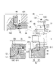
- FIG. 1 is a skeleton diagram illustrating a power transmission device.
- FIG. 2 is a schematic cross-sectional view for explaining the power transmission device.
- FIG. 3 is an enlarged view around the planetary reduction gear of the power transmission device.
- FIG. 4 is an enlarged view around the differential mechanism of the power transmission device.
- FIG. 5 is a perspective view around the differential case of the differential mechanism.
- FIG. 6 is an exploded perspective view around the differential case of the differential mechanism.
- FIG. 7 is a perspective view of the case member 6 of the differential mechanism viewed from the case member 7 side.
- FIG. 8 is a plan view of the case member 6 of the differential mechanism viewed from the case member 7 side.
- FIG. 9 is a schematic diagram of the AA cross section in FIG.
- FIG. 10 is a view taken along the line AA in FIG. 9.
- FIG. 11 is a schematic diagram of the AA cross section in FIG.
- FIG. 12 shows the upper region of the rotation axis X in FIG. 9 and shows the stepped pinion gear with a solid line.
- 13 is a perspective view of the case member 7 viewed from the opposite side of the case member 6.
- FIG. 14 is a plan view of the case member 7 viewed from the opposite side of the case member 6.
- FIG. FIG. 15 is a perspective view of the case member 7 viewed from the case member 6 side.
- FIG. 16 is a plan view of the case member 7 viewed from the case member 6 side.
- FIG. 17 is a schematic diagram of the AA cross section in FIG. 18 is a view taken along line AA in FIG. 17.
- FIG. 17 is a schematic diagram of the AA cross section
- FIG. 19 is a schematic diagram of the AA cross section in FIG.
- FIG. 20 is a schematic diagram of the AA cross section in FIG. 21A and 21B are diagrams for explaining the assembly of the case member 6 and the case member 7.
- FIG. 22A and 22B are diagrams for explaining the assembly of the case member 6 and the case member 7.
- FIG. 23A and 23B are diagrams illustrating the assembly of the case member 6 and the case member 7 according to Modification 1.
- FIG. 24A and 24B are diagrams illustrating the assembly of the case member 6 and the case member 7 according to Modification 1.
- a power transmission device is a device having at least a power transmission mechanism.
- the power transmission device is, for example, a gear mechanism and/or a differential gear mechanism.
- a second element (part, portion, etc.) connected to the first element (part, portion, etc.); a second element (part, portion, etc.) connected downstream of the first element (part, portion, etc.);
- a second element (part, section, etc.) connected upstream of an element (part, section, etc.)
- the first element and the second element are power-transmittably connected.
- the power input side is upstream, and the power output side is downstream.
- the first element and the second element may be connected via another element (clutch, other gear mechanism, etc.).
- “Overlapping when viewed from a predetermined direction” means that a plurality of elements are arranged in a predetermined direction, and has the same meaning as “overlapping in a predetermined direction”.
- the "predetermined direction” is, for example, an axial direction, a radial direction, a gravitational direction, a vehicle running direction (vehicle forward direction, vehicle backward direction), or the like. If a drawing shows that multiple elements (parts, parts, etc.) are lined up in a predetermined direction, there is a sentence in the description explaining that they overlap when viewed in a predetermined direction. can be regarded as
- not overlapped when viewed from a predetermined direction and “offset when viewed from a predetermined direction” mean that a plurality of elements are not aligned in a predetermined direction, and "not overlapped in a predetermined direction”. , is synonymous with the description of "offset in a predetermined direction".
- the "predetermined direction” is, for example, an axial direction, a radial direction, a gravitational direction, a vehicle running direction (vehicle forward direction, vehicle backward direction), or the like. If a drawing shows that multiple elements (parts, parts, etc.) are not aligned in a predetermined direction, the description of the specification includes a sentence explaining that they do not overlap when viewed in a predetermined direction. can be regarded as
- the first element is located between the second element (part, portion, etc.) and the third element (part, portion, etc.) when viewed from a predetermined direction" In the case it means that the first element can be observed to be between the second and third elements.
- the "predetermined direction” includes an axial direction, a radial direction, a gravity direction, a vehicle running direction (vehicle forward direction, vehicle backward direction), and the like. For example, when the second element, the first element, and the third element are arranged in this order along the axial direction, the first element is between the second element and the third element when viewed in the radial direction.
- the drawing shows that the first element is between the second element and the third element when viewed from a predetermined direction
- the first element is the second element when viewed from a predetermined direction in the description of the specification. It can be considered that there is a sentence explaining what is between the third element.
- Axial direction means the axial direction of the rotating shaft of the parts that make up the power transmission device.
- Rotary direction means a direction perpendicular to the rotation axis of the parts that constitute the power transmission device.
- the parts are, for example, motors, gear mechanisms, differential gear mechanisms, and the like.
- a rotating element of a planetary gear mechanism (for example, a sun gear, a carrier, a ring gear, etc.) is "fixed" to another element, which means that it may be directly fixed or fixed via another member. good.
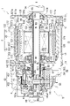
- FIG. 1 is a skeleton diagram for explaining the power transmission device 1.
- FIG. FIG. 2 is a schematic cross-sectional view for explaining the power transmission device 1.
- FIG. 3 is an enlarged view around the planetary reduction gear 4 of the power transmission device 1.
- FIG. 4 is an enlarged view around the differential mechanism 5 of the power transmission device 1.
- FIG. 1 is a skeleton diagram for explaining the power transmission device 1.
- FIG. 2 is a schematic cross-sectional view for explaining the power transmission device 1.
- FIG. 3 is an enlarged view around the planetary reduction gear 4 of the power transmission device 1.
- FIG. 4 is an enlarged view around the differential mechanism 5 of the power transmission device 1.
- the power transmission device 1 has a motor 2 , a planetary reduction gear 4 (reduction mechanism), and a differential mechanism 5 .
- the power transmission device 1 also has drive shafts 9A and 9B and a parking lock mechanism 3.
- a parking lock mechanism 3 a planetary reduction gear 4, a differential mechanism 5, and drive shafts 9A and 9B are provided along the transmission path of the output rotation of the motor 2 about the rotation axis X.
- a planetary reduction gear 4 is connected downstream of the motor 2 .
- the differential mechanism 5 is connected downstream of the planetary reduction gear 4 .
- the drive shafts 9A, 9B are connected downstream of the differential mechanism 5 .
- the drive shafts 9A and 9B are connected to one side and the other side of the differential mechanism 5 in the rotation axis X direction, respectively. Axes of the drive shafts 9A and 9B are coaxial with the rotation axis X of the motor 2 . Left and right drive wheels W, W of the vehicle are connected to the drive shafts 9A, 9B, respectively.
- the motor 2 is a rotating electric machine that has at least one of a motor function and a generator function.
- the output rotation of the motor 2 is reduced by the planetary reduction gear 4 and input to the differential mechanism 5 .
- the differential mechanism 5 transmits rotation to drive wheels W, W via drive shafts 9A, 9B.
- the main body box 10 of the power transmission device 1 has a first box 11 that houses the motor 2 and a second box 12 that is externally inserted into the first box 11 .
- the main box 10 also has a third box 13 attached to the first box 11 and a fourth box 14 attached to the second box 12 .
- the first box 11 has a cylindrical support wall portion 111 and a flange-like joint portion 112 provided at one end 111 a of the support wall portion 111 .
- the first box 11 is provided with a supporting wall portion 111 oriented along the rotation axis X of the motor 2 .
- the motor 2 is accommodated inside the support wall portion 111 .
- the joint 112 is provided in a direction orthogonal to the rotation axis X.
- the joint portion 112 is formed with an outer diameter larger than that of the support wall portion 111 .
- the second box 12 includes a cylindrical peripheral wall portion 121, a flange-shaped joint portion 122 provided at one end 121a of the peripheral wall portion 121, and a flange-shaped joint portion 123 provided at the other end 121b of the peripheral wall portion 121. ,have.
- the peripheral wall portion 121 is formed with an inner diameter that allows it to be externally inserted into the support wall portion 111 of the first box 11 .
- the first box 11 and the second box 12 are assembled together by extrapolating the peripheral wall portion 121 of the second box 12 to the supporting wall portion 111 of the first box 11 .
- a joint portion 122 on the one end 121a side of the peripheral wall portion 121 contacts the joint portion 112 of the first box 11 from the rotation axis X direction. These joints 122 and 112 are connected to each other by bolts (not shown).
- a plurality of grooves 111b are provided on the outer periphery of the support wall portion 111. As shown in FIG. The plurality of grooves 111b are provided at intervals in the rotation axis X direction. Each of the concave grooves 111b is provided over the entire circumference of the rotation axis X in the circumferential direction.
- the peripheral wall portion 121 of the second box 12 is fitted onto the support wall portion 111 of the first box 11 .
- the peripheral wall portion 121 closes the opening of the groove 111b.
- a plurality of cooling paths CP through which cooling water flows are formed between the support wall portion 111 and the peripheral wall portion 121 .
- Ring grooves 111c, 111c are formed on both sides of the region in which the concave groove 111b is provided on the outer circumference of the support wall portion 111 of the first box 11. As shown in FIG. Seal rings 113, 113 are fitted in the ring grooves 111c, 111c. These seal rings 113 are pressed against the inner periphery of the peripheral wall portion 121 fitted on the support wall portion 111 to seal the gap between the outer periphery of the support wall portion 111 and the inner periphery of the peripheral wall portion 121 .
- a wall portion 120 extending radially inward is provided at the other end 121b of the second box 12 .
- the wall portion 120 is provided in a direction perpendicular to the rotation axis X.
- An opening 120a through which the drive shaft 9A is inserted is provided in a region of the wall portion 120 that intersects with the rotation axis X.
- a cylindrical motor support portion 125 surrounding the opening 120a is provided on the surface on the side of the motor 2 (on the right side in the drawing).
- the motor support portion 125 is inserted inside a coil end 253b, which will be described later.
- the motor support portion 125 faces the end portion 21b of the rotor core 21 with a gap in the rotation axis X direction.
- the peripheral wall portion 121 of the second box 12 is thicker in the radial direction in the lower region in the vertical direction than in the upper region with respect to the mounting state of the power transmission device 1 on the vehicle.
- An oil reservoir portion 128 is provided to penetrate in the direction of the rotation axis X in this region having a large thickness in the radial direction.
- the oil reservoir portion 128 communicates with an axial oil passage 138 provided in the joint portion 132 of the third box 13 through the communication hole 112a.
- the communication hole 112 a is provided in the joint portion 112 of the first box 11 .
- the third box 13 has a wall portion 130 perpendicular to the axis X of rotation.
- a joint portion 132 having a ring shape when viewed from the rotation axis X direction is provided on the outer peripheral portion of the wall portion 130 .
- the third box 13 is located on the side opposite to the differential mechanism 5 (on the right side in the drawing).
- the joint 132 of the third box 13 is joined to the joint 112 of the first box 11 from the rotation axis X direction.
- the third box 13 and the first box 11 are connected to each other with bolts (not shown). In this state, the third box 13 closes the opening of the first box 11 on the joint portion 122 side (right side in the drawing) of the support wall portion 111 .
- an insertion hole 130a for the drive shaft 9A is provided in the central portion of the wall portion 130.
- a lip seal RS is provided on the inner circumference of the insertion hole 130a.
- the lip seal RS brings the lip portion (not shown) into elastic contact with the outer circumference of the drive shaft 9A.
- a gap between the inner periphery of the insertion hole 130a and the outer periphery of the drive shaft 9A is sealed with a lip seal RS.
- a peripheral wall portion 131 surrounding the insertion hole 130a is provided on the surface of the wall portion 130 on the first box 11 side (left side in the drawing).
- a drive shaft 9A is supported on the inner periphery of the peripheral wall portion 131 via a bearing B4.
- a motor support portion 135 is provided on the motor 2 side (on the left side in the figure) when viewed from the peripheral wall portion 131 .
- the motor support portion 135 has a tubular shape surrounding the rotation axis X with a space therebetween.
- a cylindrical connection wall 136 is connected to the outer periphery of the motor support portion 135 .
- the connection wall 136 is formed with a larger outer diameter than the peripheral wall portion 131 on the wall portion 130 side (right side in the drawing).
- the connection wall 136 is oriented along the rotation axis X and extends away from the motor 2 .
- the connection wall 136 connects the motor support portion 135 and the wall portion 130 of the third box 13 .
- the motor support portion 135 is supported by the third box 13 via the connection wall 136 .
- One end 20a side of the motor shaft 20 penetrates the inside of the motor support portion 135 from the motor 2 side to the peripheral wall portion 131 side.
- a bearing B ⁇ b>1 is supported on the inner periphery of the motor support portion 135 .
- the outer circumference of the motor shaft 20 is supported by a motor support portion 135 via a bearing B1.
- a lip seal RS is provided at a position adjacent to the bearing B1.
- an oil hole 136a which will be described later, opens on the inner periphery of the connection wall 136.
- the oil OL flows into the space (internal space Sc) surrounded by the connection wall 136 through the oil hole 136a.
- the lip seal RS is provided to prevent the oil OL in the connection wall 136 from flowing into the motor 2 side.
- the fourth box 14 has a peripheral wall portion 141 surrounding the outer periphery of the planetary reduction gear 4 and the differential mechanism 5, and a flange-shaped joint portion 142 provided at the end portion of the peripheral wall portion 141 on the second box 12 side. is doing.
- the fourth box 14 functions as a box that accommodates the planetary reduction gear 4 and the differential mechanism 5 .
- the fourth box 14 is located on the differential mechanism 5 side (left side in the figure) when viewed from the second box 12 .
- the joint 142 of the fourth box 14 is joined to the joint 123 of the second box 12 from the rotation axis X direction.
- the fourth box 14 and the second box 12 are connected to each other with bolts (not shown).
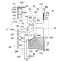
- a motor chamber Sa that houses the motor 2 and a gear chamber Sb that houses the planetary reduction gear 4 and the differential mechanism 5 are formed inside the main body box 10 of the power transmission device 1.
- the motor chamber Sa is formed inside the first box 11 between the wall 120 of the second box 12 and the wall 130 of the third box 13 .
- the gear chamber Sb is formed between the wall portion 120 of the second box 12 and the peripheral wall portion 141 of the fourth box 14 on the inner diameter side of the fourth box 14 .
- a plate member 8 is provided inside the gear chamber Sb.
- the plate member 8 is fixed to the fourth box 14 .
- the plate member 8 divides the gear chamber Sb into a first gear chamber Sb1 containing the planetary reduction gear 4 and the differential mechanism 5 and a second gear chamber Sb2 containing the parking lock mechanism 3 .
- the second gear chamber Sb2 is located between the first gear chamber Sb1 and the motor chamber Sa in the rotation axis X direction.
- the motor 2 has a motor shaft 20 , a rotor core 21 and a stator core 25 .
- Motor shaft 20 and rotor core 21 are cylindrical.
- a rotor core 21 is fitted over the motor shaft 20 .
- the stator core 25 surrounds the outer circumference of the rotor core 21 with a space therebetween.
- bearings B ⁇ b>1 and B ⁇ b>1 are externally inserted and fixed on both sides of the rotor core 21 .
- a bearing B ⁇ b>1 located on the one end 20 a side (right side in the drawing) of the motor shaft 20 when viewed from the rotor core 21 is supported on the inner periphery of the motor support portion 135 of the third box 13 .
- the bearing B1 located on the other end 20b side is supported on the inner periphery of the cylindrical motor support portion 125 of the second box 12 .
- the motor support portions 135, 125 are arranged on the inner diameter side of coil ends 253a, 253b, which will be described later.
- the motor support portions 135 and 125 are arranged to face one end portion 21a and the other end portion 21b of the rotor core 21 with a gap in the rotation axis X direction.
- the rotor core 21 is formed by laminating a plurality of silicon steel plates. Each of the silicon steel plates is fitted over the motor shaft 20 in a state where relative rotation with the motor shaft 20 is restricted.
- the silicon steel plate has a ring shape when viewed from the rotation axis X direction of the motor shaft 20 .
- N-pole and S-pole magnets are provided alternately in the circumferential direction around the rotation axis X on the outer peripheral side of the silicon steel plate.
- a stator core 25 surrounding the outer periphery of the rotor core 21 is formed by laminating a plurality of electromagnetic steel sheets.
- the stator core 25 is fixed to the inner circumference of the cylindrical support wall portion 111 of the first box 11 .
- Each of the electromagnetic steel sheets has a yoke portion 251 , a tooth portion 252 and a coil 253 .
- the yoke portion 251 is ring-shaped.
- the yoke portion 251 is fixed to the inner circumference of the support wall portion 111 . Teeth portion 252 protrudes from the inner periphery of yoke portion 251 toward rotor core 21 .
- the coil 253 is formed, for example, by winding a wire (not shown) over a plurality of teeth 252 .
- a known copper wire or the like can be used for the winding that forms the coil 253 .
- the coil 253 may have a configuration in which the winding is distributedly wound around each of the plurality of tooth portions 252 that protrude toward the rotor core 21 side, or may have a configuration in which the winding is concentratedly wound.
- the length of the coil 253 in the direction of the rotation axis X is set to be longer than the rotor core 21 .
- coil ends 253a and 253b located at both end portions of the coil 253 in the rotation axis X direction protrude from the rotor core 21 in the rotation axis X direction.
- Coil ends 253a and 253b have a symmetrical shape with tooth portion 252 interposed therebetween.
- the wall portion 120 (motor support portion 125) of the second box 12 is provided with an opening 120a.
- the other end 20b side of the motor shaft 20 passes through the opening 120a to the differential mechanism 5 side (left side in the figure) and is located in the fourth box 14 .
- the other end 20b of the motor shaft 20 faces a side gear 54A, which will be described later, inside the fourth box 14 with a gap in the rotation axis X direction.
- the motor shaft 20 is provided with a stepped portion 201 in a region located inside the fourth box 14 .
- the stepped portion 201 is positioned near the motor support portion 125 .
- a lip seal RS supported on the inner circumference of the motor support portion 125 is in contact with the outer circumference of the region between the stepped portion 201 and the bearing B1.
- the lip seal RS separates the motor chamber Sa containing the motor 2 from the gear chamber Sb in the fourth box 14 .
- An oil OL for lubricating the planetary reduction gear 4 and the differential mechanism 5 is sealed in the inner diameter side of the fourth box 14 (see FIG. 2).
- a lip seal RS is provided to prevent the oil OL from flowing into the motor chamber Sa.
- a region from the stepped portion 201 to the vicinity of the other end 20b serves as a fitting portion 202 having a spline on the outer periphery.
- the park gear 30 and the sun gear 41 are spline-fitted to the outer periphery of the fitting portion 202 .
- One side surface of the park gear 30 in the direction of the rotation axis X is in contact with the stepped portion 201 (right side in the drawing).
- One end 410a of a cylindrical base portion 410 of the sun gear 41 is in contact with the other side surface of the park gear 30 in the rotation axis X direction (left side in the figure).
- a nut N is pressed against the other end 410b of the base portion 410 from the rotation axis X direction.
- a nut N is screwed onto the other end 20 b of the motor shaft 20 .
- the sun gear 41 and the park gear 30 are sandwiched between the nut N and the stepped portion 201 so as not to rotate relative to the motor shaft 20 .
- the sun gear 41 has teeth 411 on the outer circumference of the motor shaft 20 on the other end 20b side.
- a large-diameter gear portion 431 of a stepped pinion gear 43 as a pinion gear meshes with the outer periphery of the tooth portion 411 .
- the stepped pinion gear 43 has a large-diameter gear portion 431 that meshes with the sun gear 41 and a small-diameter gear portion 432 smaller in diameter than the large-diameter gear portion 431 .
- the stepped pinion gear 43 is a gear component in which a large-diameter gear portion 431 and a small-diameter gear portion 432 are arranged in the direction of an axis line X1 parallel to the rotation axis X and integrally provided.
- the large-diameter gear portion 431 is formed with an outer diameter R ⁇ b>1 larger than the outer diameter R ⁇ b>2 of the small-diameter gear portion 432 .
- the stepped pinion gear 43 is oriented along the axis X1.
- the large diameter gear portion 431 is located on the motor 2 side (right side in the figure) of the small diameter gear portion 432 .
- the outer periphery of the small diameter gear portion 432 meshes with the inner periphery of the ring gear 42 .
- the ring gear 42 has a ring shape surrounding the rotation axis X with a space therebetween.
- a plurality of engaging teeth 421 projecting radially outward are provided on the outer periphery of the ring gear 42 .
- the plurality of engaging teeth 421 are provided circumferentially around the rotation axis X at intervals.
- Engagement teeth 421 are provided on the outer circumference of the ring gear 42 .
- a support wall portion 146 of the fourth box 14 is provided with a tooth portion 146a.
- An engagement tooth 421 is spline-fitted to the tooth portion 146a. The rotation of the ring gear 42 around the rotation axis X is restricted.
- the stepped pinion gear 43 has a through hole 430.
- the through-hole 430 penetrates the inner diameter sides of the large-diameter gear portion 431 and the small-diameter gear portion 432 in the direction of the axis X1.
- the pinion shaft 44 is inserted through the through hole 430 .
- Needle bearings NB, NB are provided on the outer circumference of the pinion shaft 44 .
- the stepped pinion gear 43 is rotatably supported via needle bearings NB, NB.
- the needle bearing NB on one side (the right side in the drawing) in the direction of the rotation axis X supports the inner periphery of the large-diameter gear portion 431 . It supports the needle bearing NB on the other side (the left side in the figure) in the direction of the rotation axis X and the inner circumference of the small diameter gear portion 432 .
- An intermediate spacer MS is interposed between the needle bearings NB, NB.
- shaft internal oil passages 440A and 440B are provided inside the pinion shaft 44.
- the in-shaft oil passage 440A extends from one end 44a (right side in the drawing) of the pinion shaft 44 to the inner diameter side of the large-diameter gear portion 431 along the axis X1.
- the in-shaft oil passage 440B extends from the other end 44b (left side in the drawing) of the pinion shaft 44 to the inner diameter side of the small diameter gear portion 432 along the axis X1.
- the pinion shaft 44 is provided with oil holes 441 , 442 , 443 and 444 .
- the oil holes 441 and 442 allow the in-shaft oil passage 440A and the outer circumference of the pinion shaft 44 to communicate with each other.
- the oil holes 443 and 444 allow the in-shaft oil passage 440B and the outer circumference of the pinion shaft 44 to communicate with each other.
- the oil hole 441 opens in a region where the needle bearing NB is provided.
- the needle bearing NB supports the inner circumference of the large-diameter gear portion 431 .
- the oil hole 441 in the pinion shaft 44 opens in a region where the stepped pinion gear 43 is externally inserted.
- the oil hole 442 opens into a gap CL1 between the axial side surface 431a of the large-diameter gear portion 431 and the facing surface 61b of the case member 6 of the differential case 50 in the direction of the axis X1.
- the oil OL that has flowed into the in-shaft oil passage 440A is discharged radially outward from the oil hole 441 .
- the oil OL discharged from the oil hole 441 lubricates the needle bearing NB externally fitted on the pinion shaft 44 .
- the oil hole 443 opens in a region where the needle bearing NB that supports the inner circumference of the small diameter gear portion 432 is provided.
- the oil hole 443 in the pinion shaft 44 opens in a region where the stepped pinion gear 43 is externally inserted.
- the oil hole 444 allows the in-shaft oil passage 440B and the outer circumference of the pinion shaft 44 to communicate with each other.
- the oil hole 444 opens into a gap CL2 between a side wall portion 432a of the small-diameter gear portion 432 in the direction of the axis X1 and a plate portion 68 of the case member 6, which will be described later.
- the clearance CL2 Into the clearance CL2, the oil OL that is raked up by the differential case 50 described later and directed toward the outer diameter side flows.
- the oil OL that has flowed into the oil hole 444 through the clearance CL2 flows into the in-shaft oil passage 440B of the pinion shaft 44 .
- the oil OL that has flowed into the in-shaft oil passage 440B is discharged radially outward from the oil hole 443 .
- the oil OL discharged from the oil hole 443 lubricates the needle bearing NB externally fitted on the pinion shaft 44 . That is, the clearance CL2 functions as an oil path that guides the oil OL that has been scraped up by the differential case 50 to the pinion shaft 44 .
- the pinion shaft 44 has a first shaft portion 445 on one longitudinal end 44a side (right side in FIG. 4).
- the first shaft portion 445 is a region protruding from the stepped pinion gear 43 .
- the first shaft portion 445 is supported by a support hole 61 a provided in the case member 6 of the differential case 50 .
- the pinion shaft 44 has a second shaft portion 446 on the other longitudinal end 44b side (left side in FIG. 4).
- the second shaft portion 446 is a region protruding from the stepped pinion gear 43 .
- the second shaft portion 446 is supported by a support hole 68 a provided in the case member 6 of the differential case 50 .
- the second shaft portion 446 is press-fitted into the support hole 68a.
- the second shaft portion 446 is supported so as not to rotate relative to the case member 6 .
- the first shaft portion 445 is a region on the one end 44a side of the pinion shaft 44 where the stepped pinion gear 43 is not externally inserted.
- the second shaft portion 446 is a region on the other end 44b side of the pinion shaft 44 where the stepped pinion gear 43 is not externally inserted. In the pinion shaft 44, the second shaft portion 446 is longer than the first shaft portion 445 in the direction of the axis X1.
- FIG. 5 is a perspective view around the differential case 50 of the differential mechanism 5.
- FIG. 6 is an exploded perspective view around the differential case 50 of the differential mechanism 5.
- FIG. 6 one stepped pinion gear 43 is omitted to expose the inside of the differential mechanism 5 .
- a differential case 50 as a case accommodates the differential mechanism 5 .
- the differential case 50 is formed by assembling the case member 6 (second case member) and the case member 7 (first case member) in the rotation axis X direction.
- the case member 6 of the differential case 50 functions as a carrier that supports the pinion shaft 44 of the planetary reduction gear 4 .
- the pinion mate shaft 51 functions as a support shaft that supports the pinion mate gear 52 .
- the pinion mate shaft 51 includes three shaft members 511 that are circumferentially spaced around the rotation axis X (see FIG. 6). An inner diameter side end of each of the shaft members 511 is connected to a central member 510 arranged on the rotation axis X. As shown in FIG. That is, the shaft members 511 are radially arranged with the central member 510 as the center.
- the pinion mate shaft 51 one obtained by integrally molding the central member 510 and the shaft member 511 can be used.
- One pinion mate gear 52 is fitted onto each of the shaft members 511 .
- Each of the pinion mate gears 52 is in contact with the central member 510 from the radially outer side of the rotation axis X. As shown in FIG. In this state, each pinion mate gear 52 is rotatably supported by the shaft member 511 .
- a spherical washer 53 is fitted onto the shaft member 511 .
- the spherical washer 53 is in contact with the spherical outer periphery of the pinion mate gear 52 .
- the side gear 54A is positioned on one side of the central member 510 in the direction of the rotation axis X, and the side gear 54B is positioned on the other side.
- the side gear 54A is rotatably supported by the case member 6.
- the side gear 54B is rotatably supported by the case member 7.
- the side gear 54A meshes with the three pinion mate gears 52 from one side in the rotation axis X direction.
- the side gear 54B meshes with the three pinion mate gears 52 from the other side in the rotation axis X direction.
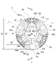
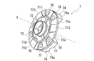
- FIG. 7 to 12 are diagrams for explaining the case member 6.
- FIG. FIG. 7 is a perspective view of the case member 6 of the differential mechanism 5 viewed from the case member 7 side.
- FIG. 8 is a plan view of the case member 6 of the differential mechanism 5 viewed from the case member 7 side.
- the plate portion 68 is cross-hatched for clarity.
- FIG. 9 is a schematic diagram of the AA cross section in FIG.
- FIG. 9 shows the arrangement of the shaft member 511 of the pinion mate shaft 51 in phantom lines.
- 10 is a view taken along the line AA in FIG. 9.
- FIG. FIG. 11 is a schematic diagram of the AA cross section in FIG. FIG.
- FIG. 11 omits illustration of the plate portion 68 and the connecting beam 62 on the far side of the paper surface.
- FIG. 11 shows the side gear 54A, the stepped pinion gear 43, and the drive shaft 9A in phantom lines.
- FIG. 12 shows the area above the rotation axis X in FIG.
- FIG. 12 shows the stepped pinion gear 43 in solid lines.
- the case member 6 has a ring-shaped base portion 61 .
- the base 61 is a plate-like member having a thickness W61 in the rotation axis X direction.
- an opening 60 is provided in the central portion of the base portion 61 .
- a cylindrical wall portion 611 surrounding the opening 60 is provided in the base portion 61 .
- the cylindrical wall portion 611 is provided on the surface of the base portion 61 opposite to the case member 7 (right side in FIG. 9). The outer circumference of the cylinder wall portion 611 is supported by the plate member 8 via the bearing B3 (see FIG. 2).
- the base 61 is provided with three connecting beams 62 extending toward the case member 7 .
- the connecting beam 62 is provided on the surface of the base portion 61 on the case member 7 side (the left side in FIG. 9).
- the three connecting beams 62 are provided at regular intervals in the circumferential direction around the rotation axis X (see FIGS. 7 and 8).
- the connecting beam 62 has a base 63 that connects to the base 61 .
- the base 63 extends in a direction perpendicular to the base 61 .
- the connecting beam 62 has a connecting portion 64 that connects the base portion 63 to the case member 7 side (the left side in the drawing).
- the connecting portion 64 is wider than the base portion 63 .
- the connecting portion 64 has a larger width in the circumferential direction around the rotation axis X than the base portion 63 .
- a circular space is formed on the inner diameter side of the connecting portion 64 when viewed from the rotation axis X direction. As shown in FIG. 6 , this space accommodates the central member 510 of the pinion mate shaft 51 , the pinion mate gear 52 and the spherical washer 53 . A spherical washer 53 is positioned on the outer circumference of the pinion mate gear 52 . A central member 510 is positioned on the inner circumference of the pinion mate gear 52 .
- the connecting portions 64 are provided at regular intervals in the circumferential direction around the rotation axis X, as shown in FIG.
- Three plate portions 68 are arranged between the connecting portions 64 .
- the plate portion 68 extends along the circumferential direction around the rotation axis X. As shown in FIG.
- the plate portion 68 connects adjacent connecting portions 64 .
- the plate portion 68 has an arc shape when viewed from the rotation axis X direction. As shown in FIG. 9 , the plate portion 68 protrudes further toward the case member 7 (to the left in the drawing) than the connecting portion 64 .
- the plate portion 68 faces the base portion 61 with a gap therebetween. A stepped pinion gear 43 and a pinion shaft 44 are accommodated in this gap (see FIG. 5).
- a stepped portion 63a is formed on the outer peripheral surface of the base portion 63 along the circumferential direction around the rotation axis X.
- the case member 6 has a first portion 6A on the case member 7 side (the left side in the drawing) and a base portion 61 side (the right side in the drawing) separated from the case member 7 with the stepped portion 63a as a boundary. and a second portion 6B.
- the diameter of the outer peripheral surface of the second portion 6B is larger than the diameter of the outer peripheral surface of the first portion 6A.
- a recess 640 is provided in the center of the connecting portion 64 in the circumferential direction around the rotation axis X.
- the concave portion 640 is recessed toward the base portion 61 with respect to the plate portion 68 .
- the recess 640 includes a bottom portion 643 and sidewall portions 644 .
- the arc-shaped bottom portion 643 extends along the circumferential direction around the rotation axis X of the recess 640 .
- the side wall portion 644 extends in the rotation axis X direction from the bottom surface portion 643 toward the plate portion 68 .
- a groove portion 645 extending in the radial direction of the rotation axis X is formed at the boundary between the bottom portion 643 and the side wall portion 644 .
- a bottom surface portion 643 of the concave portion 640 is a surface extending along a direction perpendicular to the rotation axis X. As shown in FIG. The bottom surface portion 643 is provided with a support groove 65 (second cutout portion) for supporting the shaft member 511 of the pinion mate shaft 51 .
- the support groove 65 is linearly formed along the radial line L of the ring-shaped base portion 61 when viewed from the rotation axis X direction.
- the support groove 65 crosses the central portion of the concave portion 640 in the circumferential direction around the rotation axis X from the inner diameter side to the outer diameter side.
- the support groove 65 is semicircular.
- the support groove 65 is formed by cutting the bottom surface portion 643 along the outer diameter of the shaft member 511 of the pinion mate shaft 51 .
- a circular arc portion 641 is formed along the outer circumference of the pinion mate gear 52 on the inner diameter side (the rotation axis X side) of the connecting portion 64 .
- the arc portion 641 supports the outer periphery of the pinion mate gear 52 via the spherical washer 53 .
- an oil groove 642 is provided along the radial line L described above.
- the oil groove 642 is provided in a range from the support groove 65 that supports the shaft member 511 to the gear support portion 66 fixed to the inner circumference of the connecting portion 64 .
- the gear support portion 66 is connected to the boundary portion between the base portion 63 and the connecting portion 64 .
- the gear support portion 66 is provided in a direction orthogonal to the rotation axis X.
- the gear support portion 66 has a through hole 660 in its central portion.
- the outer circumference of the gear support portion 66 is connected to the inner circumferences of the three connecting portions 64 .
- the center of the through hole 660 is located on the rotation axis X in this state.
- the gear support portion 66 is provided with a concave portion 661 on the surface opposite to the base portion 61 (on the left side in the drawing).
- a recess 661 surrounds the through hole 660 .
- a ring-shaped washer 55 is accommodated in the recess 661 .
- the washer 55 supports the back surface of the side gear 54A.
- a cylindrical wall portion 541 is provided on the back surface of the side gear 54A.
- the washer 55 is externally inserted on the cylinder wall portion 541 .
- Three oil grooves 662 are provided on the surface of the gear support portion 66 on the concave portion 661 side when viewed from the rotation axis X direction.
- the oil grooves 662 are provided circumferentially around the rotation axis X at predetermined intervals.
- the oil groove 662 extends from the inner periphery to the outer periphery of the gear support portion 66 along the radial line L described above.
- the oil groove 662 communicates with the oil groove 642 on the arc portion 641 side.
- the base portion 61 has a support hole 61a for the pinion shaft 44.
- the support hole 61a opens in a region between the connecting beams 62, 62 which are spaced apart in the circumferential direction around the rotation axis X.
- the base portion 61 is provided with a boss portion 616 surrounding the support hole 61a.
- a washer Wc (see FIG. 11) externally fitted on the pinion shaft 44 contacts the boss portion 616 from the rotation axis X direction.
- An oil groove 617 is provided in the base portion 61 in a range from the central opening 60 to the boss portion 616 . As shown in FIG. 7 , the oil groove 617 is formed in a tapered shape in which the width in the circumferential direction around the rotation axis X becomes narrower as it approaches the boss portion 616 . Oil groove 617 communicates with oil groove 618 provided in boss portion 616 .
- Bolt holes 67 , 67 are provided on both sides of the support groove 65 in the connecting portion 64 .
- the connecting portion 74 on the side of the case member 7 is joined to the connecting portion 64 of the case member 6 from the rotation axis X direction.
- Case member 6 and case member 7 are joined together by bolts B (see FIG. 5).
- the bolt B passes through the connecting portion 74 on the case member 7 side and is screwed into the bolt hole 67 .
- the plate portion 68 includes an arc-shaped base portion 680 and an outer peripheral wall 681 provided on the outer peripheral edge of the base portion 680 when viewed from the rotation axis X direction.
- the base 680 is a plate-like member arranged with its thickness direction along the rotation axis X direction.
- One end surface 680a and the other end surface 680b of the base 680 in the rotation axis X direction are flat surfaces orthogonal to the rotation axis X.
- the outer peripheral wall 681 protrudes from one end surface 680a of the base 680 in the rotation axis X direction.
- the outer peripheral wall 681 is formed over the entire length of the base 680 in the circumferential direction around the rotation axis X when viewed from the rotation axis X direction.
- An inner peripheral surface 681a of the outer peripheral wall 681 is formed so as to overlap an imaginary circle Im1 having a diameter D1.
- An inner peripheral surface 680c of the base portion 680 is formed so as to overlap an imaginary circle Im2 having a diameter D2.
- the plate portion 68 is formed with a support hole 68a penetrating through the base portion 680 in the rotation axis X direction.
- the support hole 68a and the support hole 61a are arranged concentrically along an axis X1 parallel to the rotation axis X.
- the support hole 68a is formed in the central portion of the base portion 680 in the circumferential direction around the rotation axis X. As shown in FIG.
- an area on the inner diameter side of the support hole 68a in the radial direction of the rotation axis X constitutes an oil receiving portion 682 (see FIG. 9).
- the oil receiving portion 682 receives the oil OL raked up by the rotation of the differential case 50 .
- the region of the base portion 680 on the inner diameter side of the support hole 68a is defined as one end surface 680a, the other end surface 680b, and the inner peripheral surface 680c of the base portion 680, the one end surface 680a, the other end surface 680b, and the inner peripheral surface 680c of the oil receiving portion 682. Also referred to as peripheral surface 680c.
- a concave portion 683 is provided on an inner peripheral surface 680c of the oil receiving portion 682.
- the concave portion 683 is formed by cutting out the central portion in the circumferential direction around the rotation axis X of the inner peripheral surface 680c. As viewed from the rotation axis X direction, the recess 683 opens radially inward.
- the recess 683 has inclined surfaces 683a and 683b.
- the inclined surfaces 683a and 683b have a circumferential opening width W68 that narrows from the inner peripheral surface 680c toward the outer diameter side.
- the inclined surface 683a and the inclined surface 683b of the concave portion 683 intersect at the vertex P. As shown in FIG. Vertex P is located on diameter line Lr passing through rotation axis X and axis X1.
- the inner peripheral surface 680c and recessed portion 683 of the oil receiving portion 682 are inclined radially outward from one end surface 680a toward the other end surface 680b in the rotation axis X direction.
- the inclined surfaces 683a and 683b of the recessed portion 683 are inclined radially outward from one end surface 680a toward the other end surface 680b in the direction of the rotation axis X.
- an oil groove 685 is formed in the other end surface 680b of the oil receiving portion 682 in the X direction of the rotation axis.
- the oil groove 685 connects the recess 683 and the support hole 68a.
- the oil groove 685 linearly extends from the vertex P of the recess 683 along the diameter line Lr (see FIG. 10).
- the stepped pinion gear 43 is assembled to the case member 6 while the stepped pinion gear 43 is arranged in the space between the base portion 61 and the plate portion 68 in the rotation axis X direction. .
- the pinion shaft 44 is inserted from the support hole 61a side (the direction of the arrow in the figure).
- a washer Wc is interposed between the large-diameter gear portion 431 and the base portion 61 in the rotation axis X direction.
- a washer Wc is also interposed between the small diameter gear portion 432 and the base portion 680 .
- One end 44a side and the other end 44b side of the pinion shaft 44 are supported by support holes 61a and 68a, respectively.
- the diameter of the support hole 61 a is set slightly larger than the outer diameter of the pinion shaft 44 .
- the diameter of the support hole 68 a is set to substantially match the outer diameter of the pinion shaft 44 .
- the other end 44b of the pinion shaft 44 is press-fitted into the support hole 68a. Thereby, the pinion shaft 44 is fixed to the case member 6 so as not to rotate relative to it.
- a stepped pinion gear 43 is fitted onto the pinion shaft 44 .
- the stepped pinion gear 44 is rotatably supported by the pinion shaft 44 about the axis X1.
- the stepped pinion gear 43 is assembled to the case member 6.
- the other end surface 680b of the base portion 680 faces the side wall portion 432a of the small diameter gear portion 432 with the washer Wc interposed therebetween in the rotation axis X direction.
- a clearance CL2 is formed in a region of the base portion 680 where the oil groove 685 of the oil receiving portion 682 is formed.
- the clearance CL2 is formed between the oil groove 685 in the rotation axis X direction and the side wall portion 432a of the small-diameter gear portion 432 with the washer Wc interposed therebetween.
- the oil hole 444 of the pinion shaft 44 opens into the clearance CL2.
- the case member 7 (see the phantom line in the figure) is attached to the case member 6 from the plate portion 68 side in the rotation axis X direction.
- FIG. 13 to 20 are diagrams for explaining the case member 7.
- FIG. 13 is a perspective view of the case member 7 viewed from the opposite side of the case member 6.
- FIG. 14 is a plan view of the case member 7 viewed from the side opposite to the case member 6.
- FIG. 15 is a perspective view of the case member 7 viewed from the case member 6 side.
- FIG. 16 is a plan view of the case member 7 viewed from the case member 6 side.
- the guide portion 78 is cross-hatched in order to make the position of the guide portion 78 easier to understand.
- FIG. 17 is a schematic diagram of the AA cross section in FIG.
- FIG. 17 shows the arrangement of the pinion mate gear 52 in phantom lines.
- FIG. 17 is a schematic diagram of the AA cross section in FIG.
- FIG. 17 shows the arrangement of the pinion mate gear 52 in phantom lines.
- FIG. 17 is a view taken along line AA in FIG. 17.
- FIG. 18 is a view taken along line AA in FIG. 17.
- FIG. 18 cross-hatching is added to facilitate understanding of the position of the guide portion 78 .
- FIG. 19 is a schematic diagram of the AA cross section in FIG. FIG. 19 omits illustration of the connecting portion 74 on the far side of the paper surface.
- FIG. 19 shows the stepped pinion gear 43, the plate portion 68, the side gear 54B and the drive shaft 9B in phantom lines.
- FIG. 20 is a schematic diagram of the AA cross section in FIG.
- the case member 7 has a ring-shaped base portion 71 (plate) when viewed from the rotation axis X direction.
- the base portion 71 is a plate-like member having a thickness W71 (see FIG. 19) in the rotation axis X direction.
- a through hole 70 is provided in the central portion of the base portion 71 .
- the through hole 70 penetrates the base portion 71 in the thickness direction.
- the diameter (2R4, see FIG. 14) of the outer peripheral surface 71c of the base portion 71 is slightly smaller than the diameter D1 of the virtual circle Im1 (see FIG. 8) (2R4 ⁇ D1).
- the virtual circle Im1 follows the inner peripheral surface 681a of the outer peripheral wall 681 of the plate portion 68 described above.
- one end surface 71a and the other end surface 71b of the base 71 in the rotation axis X direction are flat surfaces orthogonal to the rotation axis X.
- a cylindrical wall portion 72 and a guide portion 73 (second guide portion) are provided on one end surface 71 a of the base portion 71 .
- the cylinder wall portion 72 surrounds the through hole 70 .
- the guide portion 73 surrounds the cylindrical wall portion 72 .
- the guide portion 73 has an annular shape when viewed from the rotation axis X direction.
- three ribs 711 are provided on the inner diameter side of the guide portion 73 in the base portion 71 .
- the three ribs 711 are provided circumferentially around the rotation axis X at intervals. These ribs 711 are formed on one end face 71 a of the base portion 71 .
- the rib 711 extends linearly in the radial direction of the rotation axis X. As shown in FIG.
- the rib 711 is provided across the guide portion 73 on the outer diameter side and the tubular wall portion 72 on the inner diameter side.
- oil holes 710 (openings) penetrating through the base 71 in the thickness direction are provided between three ribs 711 arranged in the circumferential direction around the rotation axis X.
- the oil hole 710 opens to the outside and the inside of the differential case 50 in the rotation axis X direction.
- three ribs 713 are provided on the outer diameter side of the guide portion 73 in the base portion 71 .
- the three ribs 713 are provided circumferentially around the rotation axis X at intervals. These ribs 713 are formed on one end surface 71 a of the base portion 71 .
- the rib 713 linearly extends in the radial direction of the rotation axis X from the guide portion 73 toward the outer peripheral surface 71 c of the base portion 71 .
- the base portion 71 is provided with bolt accommodating portions 76 , 76 recessed toward the back side of the paper between adjacent ribs 713 . These bolt accommodating portions 76, 76 are provided in a symmetrical positional relationship with the radius line L interposed therebetween.
- the bolt accommodating portion 76 opens to the outer peripheral surface 71 c of the base portion 71 .
- a bolt insertion hole 77 is opened inside the bolt accommodating portion 76 .
- the insertion hole 77 penetrates the base portion 71 in the thickness direction (rotational axis X direction).
- three ribs 713 are formed on the outer diameter side of the oil hole 710 in the radial direction of the rotation axis X.
- the oil holes 710 are provided in the case member 7 at intervals in the circumferential direction around the rotation axis X.
- the oil hole 710 has a substantially rectangular shape when viewed from the rotation axis X direction.
- the oil hole 710 includes long side portions 710a and 710b along the circumferential direction around the rotation axis X, and short side portions 710c and 710d connecting ends of the long side portions 710a and 710b.
- the long side portion 710a is located on the outer diameter side of the long side portion 710b.
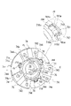
- the other end surface 71b of the base portion 71 on the case member 6 side is provided with three guide portions 78 (first guide portions).
- Each of the three guide portions 78 surrounds the oil hole 710 .
- the three guide portions 78 are spaced apart in the circumferential direction around the rotation axis X. As shown in FIG.
- the guide portion 78 is a continuous wall that surrounds the oil hole 710 and opens toward the inner diameter side. Specifically, as shown in the enlarged area of FIG. 15, the guide portion 78 has a long wall portion 781 along the long side portion 710a of the oil hole 710 and short wall portions along the short side portions 710c and 710d of the oil hole 710. 783, 784.
- the long wall portion 781 and the short wall portions 783 and 784 are integrally formed.
- the outer peripheral surface 781b of the long wall portion 781 overlaps an imaginary circle Im3 with a diameter D4.
- the diameter D4 of the virtual circle Im3 is smaller than the diameter D2 of the virtual circle Im2 (see FIG. 8) (D4 ⁇ D2).
- the virtual circle Im2 follows the inner peripheral surface 680c of the base portion 680 of the plate portion 68 of the case member 6 described above.
- the long wall portion 781 of the guide portion 78 is an arcuate wall along the circumferential direction around the rotation axis X when viewed from the rotation axis X direction.
- the short wall portions 783 and 784 extend radially inward from both ends of the long wall portion 781 in the circumferential direction around the rotation axis X, respectively.
- the short wall portions 783, 784 linearly extend along the straight lines Lm2, Lm3.
- the straight lines Lm2 and Lm3 are straight lines parallel to the straight line Lm1.
- the straight line Lm1 is a straight line that passes through the rotational axis X and an intermediate point C of the inner peripheral surface 781a of the long wall portion 781 in the circumferential direction around the rotational axis X.
- the boundary between the oil hole 710 and the guide portion 78 is indicated by a broken line.
- an inner peripheral surface 781a of the long wall portion 781 and inner peripheral surfaces 783a and 784a of the short wall portions 783 and 784 are located on the front side of the paper surface from the broken line.
- the long side portion 710a of the oil hole 710 and the inner peripheral surface 781a of the short wall portions 783, 783 are located on the back side of the paper surface from the broken line.
- the inner peripheral surface 781a is connected to the long side portion 710a without a step.
- the inner peripheral surfaces 783a and 784a are connected to the short side portions 710d and 710c without steps.
- the guide portions 73 and 78 extend away from the base portion 71 in the rotation axis X direction.
- the inner peripheral surface 731 of the guide portion 73 is a flat surface parallel to the rotation axis X when viewed from the radial direction of the rotation axis X.
- a long side portion 710a of the oil hole 710 is connected to an inner peripheral surface 731 of the guide portion 73 on the one end surface 71a side of the base portion 71 in the rotation axis X direction.
- a long side portion 710a of the oil hole 710 is an inclined surface.
- the long side portion 710a is inclined so as to be located on the outer diameter side as it is separated from the inner peripheral surface 731 of the guide portion 73 in the rotation axis X direction.
- the long side portion 710a of the oil hole 710 is connected to the inner peripheral surface 781a of the long wall portion 781 of the guide portion 78 on the other end surface 71b side of the base portion 71 in the rotation axis X direction.
- An inner peripheral surface 781a of the long wall portion 781 of the guide portion 78 is an inclined surface.
- the inner peripheral surface 781a is inclined so as to be located on the outer diameter side as it separates from the inner peripheral surface 731 of the guide portion 73 in the rotation axis X direction.
- the inclination angle of the inner peripheral surface 781 a of the long wall portion 781 is the same as the inclination angle of the long side portion 710 a of the oil hole 710 .
- the other end surface 71b of the base portion 71 on the case member 6 side is provided with three connecting portions 74 (convex portions) that protrude toward the case member 6 side.
- the connecting portions 74 are provided at regular intervals in the circumferential direction around the rotation axis X.
- the connecting portion 74 has a tip surface 743 protruding toward the case member 6 .
- the connecting portion 74 also has side wall portions 744 that connect both end portions of the distal end surface 743 in the circumferential direction around the rotation axis X and the base portion 71 .
- the connecting portion 74 has a width W2 in the circumferential direction.
- the recess 640 of the connecting portion 64 on the case member 6 side has a circumferential width W1 (see FIG. 5).
- Width W2 is smaller than width W1.
- the width W1 means the length from the side wall portion 644 connected to one end of the bottom portion 643 in the circumferential direction around the rotation axis X to the side wall portion 644 connected to the other end.
- the width W2 means the length from the side wall portion 744 connected to one end in the circumferential direction of the distal end surface 743 around the rotation axis X to the side wall portion 744 connected to the other end.
- the tip surface 743 of the connecting portion 74 is an arc-shaped surface extending along the circumferential direction around the rotation axis X when viewed from the rotation axis X direction.
- the side wall portion 744 extends from the distal end surface 743 toward the base portion 71 along the rotation axis X direction.
- a bolt insertion hole 77 is opened in the tip surface 743 .
- One end of the bolt insertion hole 77 opens into the bolt accommodating portion 76 (see FIG. 13) and penetrates the base portion 71 in the thickness direction (rotational axis X direction).
- the other end of the through hole 77 is open to the tip surface 743 .
- the tip surface 743 is provided with a support groove 75 (first notch).
- the support groove 75 supports the pinion mate shaft 51 .
- the support groove 75 is formed between the bolt insertion holes 77 in the circumferential direction around the rotation axis X. As shown in FIG.
- the support groove 75 is linearly formed along the radius line L of the base 71 when viewed from the rotation axis X direction.
- the support groove 75 is formed across the connecting portion 74 from the inner diameter side to the outer diameter side.
- the support groove 75 is semicircular.
- the outer peripheral surface 74 a of the connecting portion 74 protrudes radially outward of the rotation axis X from the outer peripheral surface 71 c of the base portion 71 .
- the outer peripheral surface 74 a of the connecting portion 74 and the outer peripheral surface 71 c of the base portion 71 are connected by a stepped portion 79 . That is, the stepped portion 79 is provided on the outer peripheral surface of the boundary between the connecting portion 74 and the base portion 71 .
- the outer peripheral surface 74a is positioned on the connecting portion 74 side of the stepped portion 79, and the outer peripheral surface 71c is positioned on the base portion 71 side.
- a diameter R3 of the outer peripheral surface 74a is longer than a diameter R4 of the outer peripheral surface 71c.
- the radii R3 and R4 mean radii from the rotation axis X, respectively.
- an arc portion 741 is provided on the inner diameter side (the rotation axis X side) of the connecting portion 74 .
- Arc portion 741 extends along the outer periphery of pinion mate gear 52 .
- the arc portion 741 supports the outer periphery of the pinion mate gear 52 via the spherical washer 53 (see FIG. 17).
- an oil groove 742 is provided along the radial line L described above.
- the oil groove 742 is provided in a range from the support groove 75 of the shaft member 511 to the base portion 71 positioned on the inner circumference of the connecting portion 74 .
- the oil groove 742 communicates with the oil groove 712 provided in the other end surface 71 b of the base portion 71 .
- the oil groove 712 is provided along the radius line L when viewed from the rotation axis X direction.
- the oil groove 712 is formed up to the through hole 70 provided in the base portion 71 .
- a ring-shaped washer 55 is placed on the other end surface 71 b of the base portion 71 , as shown in the lower enlarged area of FIG. 19 .
- the washer 55 supports the back surface of the side gear 54B.
- a cylindrical wall portion 540 is provided on the back surface of the side gear 54B.
- the washer 55 is externally inserted on the cylinder wall portion 540 .
- an oil groove 721 is formed on the inner circumference of the cylindrical wall portion 72 surrounding the through hole 70 .
- Oil groove 721 is formed at a position that intersects with oil groove 712 .
- An oil groove 721 is provided on the inner periphery of the cylindrical wall portion 72 along the rotation axis X over the entire length of the cylindrical wall portion 72 in the rotation axis X direction.
- 21A and 21B are diagrams for explaining the assembly of the case member 6 and the case member 7.
- FIG. 22A and 22B are diagrams for explaining the assembly of the case member 6 and the case member 7.
- FIG. 21 shows the state before the case members 6 and 7 are assembled.
- FIG. 22 shows the state after the case members 6 and 7 are assembled.
- 21 and 22 show the differential case 50 viewed from the AA direction in FIG. In FIGS. 21 and 22, the connecting portions 64 and 74 are hatched for easy viewing.
- 21 and 22 show the shaft member 511 of the pinion mate shaft 51 in phantom lines.
- the differential case 50 is constructed by assembling the case member 6 and the case member 7 in the rotation axis X direction.
- the rotation axis X direction is along the assembly direction of the differential case 50 .
- the connection portion 74 (projection) of the case member 7 is inserted into the recess 640 of the connection portion 64 of the case member 6 .
- the length L2 of the side wall portion 744 of the case member 7 in the rotation axis X direction matches the length L1 of the side wall portion 644 of the case member 6 in the rotation axis X direction. Therefore, as shown in FIG. 22 , the tip surface 743 of the connecting portion 74 inserted into the recess 640 contacts the bottom surface portion 643 . Thereby, the case member 7 and the case member 6 are positioned in the rotation axis X direction.
- the outer peripheral surface 71 c of the base portion 71 of the case member 7 is fitted into the inner peripheral surface 681 a of the outer peripheral wall 681 of the plate portion 68 of the case member 6 .
- the case member 7 and the case member 6 are arranged concentrically on the rotation axis X. As shown in FIG. 21 , the case member 7 and the case member 6 are arranged concentrically on the rotation axis X. As shown in FIG.
- case member 6 and the case member 7 are connected by screwing the bolt B (see FIG. 5) passing through the connecting portion 74 on the case member 7 side into the bolt holes 67, 67 on the case member 6 side. joined to each other.
- the support groove 65 of the bottom surface 643 and the support groove 75 of the tip surface 743 are formed at overlapping positions when viewed from the rotation axis X direction.
- the semicircular support grooves 65, 75 face each other.
- the support grooves 65 and 75 are symmetrical with respect to the bottom surface portion 643 and the tip end surface 743 .
- the openings of the support grooves 65 and 75 communicate with each other to form a circular hole along the outer diameter of the shaft member 511 as a whole. The shaft member 511 is held by passing through this circular hole.
- the width W1 of the recess 640 in the circumferential direction around the rotation axis X is greater than the width W2 of the connecting portion 74 in the circumferential direction (W1>W2). Therefore, as shown in FIG. 22, the side wall portion 644 of the recess 640 faces the side wall portion 744 of the connecting portion 74 with a gap therebetween.
- This gap serves as an oil passage 56 that communicates the inside and outside of the differential case 50 .
- the oil passages 56 are formed on both end sides of the connecting portion 74 in the circumferential direction around the rotation axis X. As shown in FIG.
- the width of each oil passage 56 in the circumferential direction around the rotation axis X is (W1-W2)/2.
- the oil passage 56 is positioned between the recess 640 and the connecting portion 74 in the circumferential direction around the rotation axis X of the differential case 50 .
- the positions of the oil passages 56 are indicated by hatching in the case member 6.
- the oil passage 56 extends radially outward of the rotating shaft X from the inner diameter side end of the connecting portion 64 and opens to the outer peripheral surface of the differential case 50 .
- the pinion mate gear 52 and the side gear 54B are accommodated on the inner diameter side of the connecting portion 64 .
- the oil OL stirred by the pinion mate gear 52 and the side gear 54B flows into the inner diameter side end portion of the oil passage 56 .
- the oil passage 56 discharges the oil OL to the outside of the differential case 50 by centrifugal force.
- the oil passage 56 has a longitudinal shape extending along the rotation axis X direction.
- a groove portion 645 is positioned at one end of the oil passage 56 in the rotation axis X direction.
- the groove portion 645 is formed at the boundary between the bottom portion 643 and the side wall portion 644 .
- the groove portion 645 extends in the radial direction of the rotation axis X.
- the base portion 71 of the case member 7 is positioned at the other end of the oil passage 56 in the direction of the rotation axis X. As shown in FIG.
- the outer peripheral surface 71 c of the base portion 71 of the case member 7 is fitted into the inner peripheral surface 681 a of the outer peripheral wall 681 of the plate portion 68 of the case member 6 .
- the guide portion 78 of the case member 7 is arranged on the inner diameter side of the oil receiving portion 682 of the case member 6 .
- the tip end surface 78a of the guide portion 78 is arranged between one end surface 680a and the other end surface 680b of the oil receiving portion 682 in the rotation axis X direction.
- the guide portion 78 of the case member 7, the oil receiving portion 682 of the case member 6, and the pinion shaft 44 overlap in the radial direction of the rotation axis X. As shown in FIG.
- FIG. 20 illustrates a diameter line Lr passing through the rotation axis X and the axis X1.
- the oil hole 710 of the case member 7, the guide portion 78, the recessed portion 683 of the case member 6, the oil groove 685, the oil hole 444 of the pinion shaft 44, and the in-shaft oil passage 440B are aligned with the diameter line. They are arranged in order along Lr.
- the oil hole 710, the guide portion 78, the recess 683, the oil groove 685, the oil hole 444, and the in-shaft oil passage 440B have overlapping portions.
- a vertex P of the recess 683 is arranged on the diameter line Lr.
- a bearing B2 is externally fitted on the tubular wall portion 72 of the case member 7. As shown in FIG. The inner race of the bearing B2 abuts against a stepped portion 722 provided on the outer periphery of the cylindrical wall portion 72 from the rotation axis X direction.
- the bearing B ⁇ b>2 externally inserted into the cylindrical wall portion 72 is held by the support portion 145 of the fourth box 14 .
- a tubular wall portion 72 of the differential case 50 is rotatably supported by the fourth box 14 (see FIG. 4) via a bearing B2.
- the drive shaft 9B penetrating through the opening 145a of the fourth box 14 is inserted into the supporting portion 145 from the rotation axis X direction.
- the drive shaft 9B is rotatably supported by a support portion 145.
- the cylinder wall portion 72 functions as a shaft support portion that supports the outer circumference of the drive shaft 9B.
- a lip seal RS is fixed to the inner circumference of the opening 145a.
- a lip portion (not shown) of the lip seal RS is in elastic contact with the outer circumference of the cylinder wall portion 540 of the side gear 54B externally fitted on the drive shaft 9B. As a result, the gap between the outer circumference of the cylindrical wall portion 540 of the side gear 54B and the inner circumference of the opening 145a is sealed.
- the case member 6 of the differential case 50 is supported by the plate member 8 via a bearing B3 externally inserted into the cylindrical wall portion 611 (see FIG. 2).
- a drive shaft 9A passing through the insertion hole 130a of the third box 13 is inserted into the case member 6 from the rotation axis X direction.
- the drive shaft 9A is provided across the inner diameter side of the motor shaft 20 of the motor 2 and the sun gear 41 of the planetary reduction gear 4 in the rotation axis X direction.
- side gears 54A and 54B are spline-fitted to the outer peripheries of the tip portions of the drive shafts 9A and 9B.
- the side gears 54A, 54B and the drive shafts 9A, 9B are connected to each other so as to rotate about the rotation axis X together.
- the side gears 54A and 54B are arranged opposite to each other with a gap in the rotation axis X direction.
- a central member 510 of the pinion mate shaft 51 is positioned between the side gears 54A, 54B.
- three shaft members 511 extend radially outward from central member 510 .
- a pinion mate gear 52 is supported on each of the shaft members 511 of the pinion mate shaft 51 .
- a side gear 54A is positioned on one side of the pinion mate gear 52 in the direction of the rotation axis X, and a side gear 54B is positioned on the other side.
- the pinion mate gear 52 is assembled to the side gears 54A and 54B in a state in which their teeth are meshed with each other.
- lubricating oil OL is stored inside the fourth box 14 .
- the lower side of the differential case 50 is positioned within the stored oil OL.
- the oil OL is stored, for example, up to a height where the connecting beam 62 is positioned within the oil OL when the connecting beam 62 is positioned at the lowest side.
- the stored oil OL is raked up by the differential case 50 rotating around the rotation axis X when the output rotation of the motor 2 is transmitted.
- an oil catch portion 15 is provided on the upper portion of the fourth box 14 .
- the oil catch portion 15 communicates with an oil passage 151a extending radially inside the fourth box 14 .
- the inner diameter side end of the oil passage 151a opens between the lip seal RS and the bearing B2.
- the oil catch portion 15 also communicates with an oil hole 136a (see FIG. 2) provided in the cylindrical connection wall 136 of the third box 13 via a pipe (not shown).
- the oil OL is supplied to the internal space Sc of the connection wall 136 through the guide portion 154 of the oil catch portion 15 and the pipe 127 .
- the third box 13 is provided with a radial oil passage 137 communicating with the internal space Sc.
- the radial oil passage 137 extends radially downward from the internal space Sc.
- the radial oil passage 137 communicates with an axial oil passage 138 provided inside the joint portion 132 .
- a joint portion 112 of the first box 11 is provided with a communication hole 112a.
- the axial oil passage 138 communicates with an oil reservoir 128 provided in the lower portion of the second box 12 via a communication hole 112a.
- the oil reservoir portion 128 penetrates the inside of the peripheral wall portion 121 in the rotation axis X direction.
- the oil reservoir portion 128 communicates with the second gear chamber Sb2 provided in the fourth box 14 .
- a planetary reduction gear 4 As shown in FIG. 1, in the power transmission device 1, a planetary reduction gear 4, a differential mechanism 5, and a drive shaft 9 (9A, 9B) are provided along the transmission path of the output rotation of the motor 2. ing.
- the sun gear 41 serves as an input portion for the output rotation of the motor 2 .
- a differential case 50 that supports the stepped pinion gear 43 serves as an output portion for the input rotation.
- the stepped pinion gear 43 (the large-diameter gear portion 431 and the small-diameter gear portion 432) rotates around the axis X1 due to the rotation input from the sun gear 41 side. do.
- the small diameter gear portion 432 of the stepped pinion gear 43 meshes with the ring gear 42 fixed to the inner circumference of the fourth box 14 . Therefore, the stepped pinion gear 43 revolves around the rotation axis X while rotating around the axis X1.
- the drive shaft 9B is positioned on the inner circumference of the revolution track of the stepped pinion gear 43 .
- the outer diameter R2 of the small-diameter gear portion 432 of the stepped pinion gear 43 is smaller than the outer diameter R1 of the large-diameter gear portion 431 (see FIG. 3).
- the differential case 50 (case member 6, case member 7) supporting the stepped pinion gear 43 rotates around the rotation axis X at a rotation speed lower than the rotation input from the motor 2 side. Therefore, the rotation input to the sun gear 41 of the planetary reduction gear 4 is greatly reduced by the stepped pinion gear 43 . The reduced rotation is output to the differential case 50 (differential mechanism 5).
- lubricating oil OL is stored inside the fourth box 14 . Therefore, the stored oil OL is raked up by the differential case 50 rotating around the rotation axis X when the output rotation of the motor 2 is transmitted.
- the raking oil OL forms a meshing portion between the sun gear 41 and the large diameter gear portion 431, a meshing portion between the small diameter gear portion 432 and the ring gear 42, and a meshing portion between the pinion mate gear 52 and the side gears 54A and 54B. is lubricated. Most of the oil OL scraped up by the differential case 50 flows into the oil catch portion 15 .
- the end on the inner diameter side of the oil passage 151a opens to the inner circumference of the support portion 145 (see FIG. 2). Therefore, the oil OL that has flowed into the oil passage 151a is discharged into the clearance Rx between the inner periphery of the support portion 145 of the fourth box 14 and the tubular wall portion 540 of the side gear 54B.
- a part of the oil OL discharged into the clearance Rx lubricates the bearing B2 supported by the support portion 145 .
- the oil OL that has lubricated the bearing B2 moves outside the differential case 50 (bearing B2 side) toward the outer diameter side due to the centrifugal force generated by the rotation of the differential case 50 .
- a guide portion 73 having an annular shape when viewed from the rotation axis X direction is provided on the outer diameter side of the differential case 50 . Therefore, the oil OL that has moved to the outer diameter side is captured by the guide portion 73 .
- a rib 711 is provided on the inner peripheral side of the guide portion 73 .
- a recess is formed between the guide portion 73 , the rib 711 and the cylindrical wall portion 72 .
- This depression makes it easier for the oil OL to accumulate on the inner peripheral side of the guide portion 73 .
- an oil hole 710 is provided along the inner peripheral surface 731 of the guide portion 73 . Further movement of the oil OL to the outer diameter side is prevented by the guide portion 73 .
- the oil OL whose movement is hindered passes through an oil hole 710 opening on the inner circumference of the guide portion 73 toward the case member 6 .
- the oil OL reaches the inner peripheral surface 731 of the guide portion 73 due to the centrifugal force caused by the rotation of the differential case 50 . Most of the oil OL that reaches the inner peripheral surface 731 of the guide portion 73 flows into the oil hole 710 that opens in the rotation axis X direction without getting over the guide portion 73 .
- oil OL supplied to oil hole 710 moves to guide portion 78 .
- the long side portion 710a of the oil hole 710 and the inner peripheral surface 781a of the long wall portion 781 of the guide portion 78 are inclined so as to be positioned radially outward as they move away from the inner peripheral surface 731 of the guide portion 73 in the rotation axis X direction.
- the oil OL passing through the oil hole 710 and the guide portion 78 moves along the slope while receiving centrifugal force. This promotes movement of the oil OL toward the case member 6 side.
- this inclination can prevent the oil OL that has moved from the guide portion 73 to the case member 6 side to return to the guide portion 73 side and be discharged to the outside of the differential case 50 .
- the guide portion 78 is a continuous wall composed of a long wall portion 781 and short wall portions 783 and 784 (see FIG. 18).
- the guide portion 78 opens toward the inner diameter side.
- the oil OL scattering inside the differential case 50 can also be caught (white arrow in FIG. 19).
- the oil OL that has moved through the guide portion 78 from the oil hole 710 toward the case member 6 is discharged from the tip surface 78a.
- the inner peripheral surface 680c of the oil receiving portion 682 and the recessed portion 683 cross the tip end surface 78a of the guide portion 78 from the base portion 71 side of the case member 7 in the rotation axis X direction to the pinion gear 43 side. Accordingly, the oil OL discharged from the tip surface 78a of the guide portion 78 moves radially outward due to centrifugal force, and is then caught by the inner peripheral surface 680c of the oil receiving portion 682 and the recess 683 (see FIG. 20).
- the inner peripheral surface 680c and the recessed portion 683 are inclined so as to be positioned radially outward as they move away from the guide portion 78 in the rotation axis X direction.
- the oil OL caught by the recessed portion 683 moves along the inclination from the one end surface 680a side of the oil receiving portion 682 to the other end surface 680b side. Also, most of the oil OL caught by the inner peripheral surface 680c gathers in the recess 683 in the process of moving along the slope.
- the oil OL in the recess 683 moves on the inclined surfaces 683a and 683b in the circumferential direction about the rotation axis X due to centrifugal force and gathers around the vertex P. .
- the recess 683 communicates with the oil groove 685 (clearance CL2) at the vertex P.
- the oil OL in the recessed portion 683 is discharged to the oil groove 685 after gathering at the apex P by centrifugal force.
- the oil OL in the oil groove 685 moves radially outward due to centrifugal force and flows into the oil hole 444 of the pinion shaft 44 .
- the washer Wc is also lubricated with the oil OL.
- the oil OL that has flowed into the oil hole 444 of the pinion shaft 44 moves to the in-shaft oil passage 440B and is finally discharged from the oil hole 443 (see FIG. 4). At this time, the oil OL lubricates the needle bearing NB.
- part of the oil OL discharged into the clearance Rx passes through an oil groove 721 provided in the inner circumference of the cylindrical wall portion 72 of the case member 7, as shown in FIG.
- the oil OL that has passed through the oil groove 721 is supplied to the washer 55 that supports the back surface of the side gear 54B and lubricates the washer 55 .
- the oil OL passes through an oil groove 712 provided in the base portion 71 of the case member 7 and an oil groove 742 provided in the arc portion 741 .
- the oil OL that has passed through the oil groove 742 is supplied to the spherical washer 53 that supports the back surface of the pinion mate gear 52 to lubricate the spherical washer 53 .
- a portion of the oil OL captured by the oil catch portion 15 is supplied to an oil hole 136a (see FIG. 2) provided in the cylindrical connection wall 136 of the third box 13 through a pipe (not shown). be.
- the oil OL discharged from the oil hole 136a into the internal space Sc is stored in the internal space Sc.
- Oil OL also lubricates bearing B4 supported by peripheral wall portion 131 of third box 13 .
- a portion of the oil OL discharged into the internal space Sc moves to the other end 20b side of the motor shaft 20 through the gap between the outer circumference of the drive shaft 9A and the inner circumference of the motor shaft 20 .
- the other end 20b of the motor shaft 20 is inserted inside the cylindrical wall portion 541 of the side gear 54A.
- a communication path 542 is provided on the inner periphery of the cylindrical wall portion 541 to communicate with the back surface of the side gear 54A. Therefore, part of the oil OL that has moved to the other end 20 b side of the motor shaft 20 and is discharged inside the cylinder wall portion 541 passes through the communication path 542 .
- the oil OL that has passed through the communication path 542 is supplied to the washer 55 on the back surface of the side gear 54A to lubricate the washer 55 .
- the oil OL that has lubricated the washer 55 on the back surface of the side gear 54A passes through an oil groove 662 provided in the gear support portion 66 of the case member 6 and an oil groove 642 provided in the arc portion 641. .
- the oil OL that has passed through the oil groove 642 is supplied to the spherical washer 53 that supports the back surface of the pinion mate gear 52 to lubricate the spherical washer 53 .
- the internal space Sc of the third box 13 includes a radial oil passage 137, an axial oil passage 138, a communication hole 112a, and an oil reservoir 128 provided in the lower portion of the second box 12. , to the second gear chamber Sb2 provided in the fourth box 14 . Therefore, the oil OL inside the internal space Sc is held at the same height position as the oil OL stored inside the fourth box 14 .
- the oil OL in the fourth box 14 is raked up when the drive wheels W rotate and is used to lubricate the bearings and the meshing portions of the gears.
- the oil OL used for lubrication is returned into the fourth box 14 and raked up again.
- the connecting portion 74 of the case member 7 is inserted into the concave portion 640 of the case member 6 and brought into contact therewith, so that the support grooves 65 and 75 face each other to support the shaft member 511 .
- a circular hole is formed.
- the case members 6 and 7 can be assembled with the shaft member 511 previously arranged in the support groove 65 of the recess 640 .
- the three shaft members 511 can be arranged in the case member 6 in a state of being connected to the central member 510 in advance.
- a pinion mate shaft 51 in which the shaft member 511 and the central member 510 are integrally formed can also be used.
- the width W2 of the connecting portion 74 in the circumferential direction around the rotation axis X is set smaller than the width W1 of the recess 640 in the circumferential direction. Therefore, the connecting portion 74 can be easily inserted into the concave portion 640 .
- a groove portion 645 is formed at the boundary between the bottom portion 643 and the side wall portion 644 of the case member 6 .
- the groove portion 645 extends from the inner diameter side of the rotating shaft X to the outer diameter side along the oil passage 56 .
- the oil OL stirred by the pinion mate gear 52 and the side gears 54A and 54B enters the groove portion 645 and flows along the groove portion 645 toward the outer diameter side. This improves the ability of the oil OL to be discharged from the inside of the differential case 50 to the outside.
- the power transmission device 1 is a differential case 50 (case) configured by assembling the case member 7 (first case member) and the case member 6 (second case member); and a shaft member 511 supported by the differential case 50 .
- the power transmission device 1 includes a connecting portion 74 (convex portion) that is provided in the case member 7 and protrudes in the rotation axis X direction (axial direction) along the assembly direction of the differential case 50; and a concave portion 640 provided in the case member 6 and recessed in the rotation axis X direction.
- the shaft member 511 is supported by the connecting portion 74 in the recess 640 .
- the degree of freedom in assembly is improved.
- the shaft member 511 is previously arranged in the recess 640 of the case member 6 .
- the connecting portion 74 of the case member 7 is inserted into the recess 640 and brought into contact with the shaft member 511 to assemble the case members 6 and 7 .
- the degree of freedom of assembly can be improved.
- the shaft member 511 may be inserted into the circular hole formed by the support grooves 65 and 75 for assembly.
- the shaft member 511 and the central member 510 of the pinion mate shaft 51 are molded separately.
- the central member 510 is pre-arranged in the case member 6 together with the pinion mate gear 52 and the spherical washer 53, and the case member 7 is assembled.
- the shaft member 511 is then inserted into the circular hole and connected to the central member 510 .
- the case member 7 preferably has the support groove 75 (first notch) on the tip surface 743 (tip) of the connecting portion 74 .
- the shaft member 511 is accommodated in the support groove 75 .
- the shaft member 511 is supported within the recess 640 while being accommodated in the support groove 75 of the connecting portion 74 . Thereby, the shaft member 511 can be stably supported.
- the case member 6 preferably has a support groove 65 (second notch) for accommodating the shaft member 511 in the recess 640 .
- the shaft member 511 is supported within the recess 640 while being accommodated in the support groove 65 of the recess 640 . Thereby, the shaft member 511 can be stably supported. Further, when the support groove 65 is provided in addition to the support groove 75, the shaft member 511 is accommodated in the support groove 75 and the support groove 65 from both sides in the rotation axis X direction. It can be stably supported.
- the support grooves 65, 75 are formed as semicircular cutouts that are symmetrical with respect to the contact surface (the tip end surface 743 and the bottom surface portion 643) when the connecting portion 74 is accommodated in the recess 640. can be done. Thereby, the support grooves 65 , 75 form circular holes matching the outer diameter of the shaft member 511 . By accommodating the shaft member 511 in this circular hole, the shaft member 511 can be stably supported.
- the power transmission device 1 preferably has the oil passage 56 between the recess 640 and the connecting portion 74 in the circumferential direction (circumferential direction) of the differential case 50 around the rotation axis X.
- the oil passage 56 opens to the outer peripheral surface of the differential case 50 .
- the oil passage 56 facilitates the discharge of the oil OL from the inside of the differential case 50 to the outside, and reduces the agitation resistance of the oil OL of the pinion mate gear 52 arranged inside the differential case 50.
- the circumferential width W1 of the concave portion 640 around the rotation axis X is set larger than the circumferential width W2 of the connecting portion 74 . Accordingly, when the connecting portion 74 is inserted into the recess 640, the side wall portion 644 of the recess 640 faces the side wall portion 744 of the connecting portion 74 with a gap therebetween. In the embodiment, this gap is used as the oil passage 56 . As a result, there is no need to separately form the oil passage 56, and the manufacturing cost can be reduced.
- the oil passage 56 is not limited to the gap between the side wall portion 644 and the side wall portion 744, and may be formed separately.
- the oil passage 56 preferably has a longitudinal shape extending in the rotation axis X direction.
- the oil passage 56 positioned between the recess 640 and the connecting portion 74 has a longitudinal shape extending in the direction of the rotation axis X, there is play between the recess 640 and the connecting portion 74 . This makes it easier to insert the connecting portion 74 into the recessed portion 640 , making it easier to assemble the case member 6 and the case member 7 .
- the power transmission device 1 preferably has a plurality of shaft members 511 .
- case member 6 and case member 7 can be assembled with shaft member 511 arranged in case member 6 in advance.
- the degree of freedom in assembly can be improved.
- the pinion mate shaft 51 includes three shaft members 511 in the embodiment, the number of shaft members 511 may be two or four or more.
- the power transmission device 1 preferably has three or more shaft members 511 . According to the configuration of the embodiment, even when three or more shaft members 511 are provided, the shaft members 511 can be arranged in the case member 6 in advance for assembly. As a result, the degree of freedom in assembly can be improved.
- the power transmission device 1 preferably has a pinion mate shaft 51 composed of a plurality of shaft members 511 and a central member 510 supporting the plurality of shaft portions.
- the shaft member 511 and the central member 510 can be pre-connected and arranged in the case member 6 for assembly. As a result, the degree of freedom in assembly can be improved.
- the state in which the shaft member 511 and the central member 510 are connected in advance also includes the case where the shaft member 511 and the central member 510 are integrally molded.
- the central member 510 and the plurality of shaft members 511 are preferably integrally molded.
- the assembly efficiency can be improved.
- the case member 7 preferably has a base portion 71 (plate).
- the base portion 71 is connected to the connecting portion 74 and fitted to the case member 6 .
- the case member 6 has a plate portion 68 that connects to the recessed portion 640 of the connecting portion 64 .
- the base portion 71 is provided on the side of the connecting portion 74 away from the case member 6 .
- the plate portion 68 is provided on the case member 7 side of the concave portion 640 .
- the case member 7 preferably has a stepped portion 79 provided on the outer peripheral surface of the boundary between the base portion 71 and the connecting portion 74 .
- the diameter R4 of the outer peripheral surface 71c of the stepped portion 79 on the base portion 71 side is smaller than the diameter R3 of the outer peripheral surface 74a on the connecting portion 74 side.
- the side of the connecting portion 74 that supports the shaft member 511 in the case member 7 is thickened to increase rigidity, and the side of the base portion 71, which does not require rigidity, is thinned to reduce the weight of the differential case 50. be able to.
- the case member 6 preferably has a first portion 6A on the side of the case member 7; and a second portion 6 ⁇ /b>B on the side away from the case member 7 .
- the case member 6 has a stepped portion 63a on the outer peripheral surface of the boundary between the first portion 6A and the second portion 6B.
- the thicknesses of the first portion 6A and the second portion 6B of the case member 6 in the radial direction of the rotation axis X can be changed, and the weight of the differential case 50 can be reduced.
- FIG. 23A and 23B are diagrams illustrating the assembly of the case member 6 and the case member 7 in Modification 1.
- FIG. 24A and 24B are diagrams for explaining the assembly of the case member 6 and the case member 7 in Modification 1.
- FIG. 23 shows the state before assembly
- FIG. 24 shows the state after assembly.
- the case member 6 has a recess 640A recessed in the rotation axis X direction.
- the case member 7 has a connecting portion 74A, which is a convex portion that protrudes in the rotation axis X direction.
- a support groove for supporting shaft member 511 is not formed in recess 640A and connecting portion 74A.
- the recessed portion 640A of the case member 6 has a bottom portion 643A and side wall portions 644A connected to both ends of the bottom portion 643A in the circumferential direction around the rotation axis X.
- the bottom portion 643A is formed to have an arcuate cross section along the outer diameter of the shaft member 511 .
- the connecting portion 74A of the case member 7 has a tip surface 743A and a side wall portion 744A.
- the side wall portions 744A are connected to both end sides in the circumferential direction around the rotation axis X of the distal end surface 743A.
- the circumferential width W10 of the recess 640A is set larger than the circumferential width W20 of the connecting portion 74A. That is, the connecting portion 74A can be inserted into the recess 640A.
- the width W10 means the length from one sidewall portion 644A connected to the bottom surface portion 643A to the other sidewall portion 644A.
- the width W20 means the length from one side wall portion 744A connected to the tip surface 743A to the other side wall portion 744A.
- the length L20 of the connecting portion 74A in the direction of the rotation axis X matches the length L10 shown on the case member 6.
- the length L10 means the length from the tangent line Im10 passing through the outer peripheral edge of the shaft member 511 closest to the case member 7 to the end of the side wall portion 644A on the case member 7 side.
- the case member 6 and the case member 7 can be assembled by arranging the shaft member 511 in the recess 640A of the case member 6 in advance.
- the shaft member 511 is arranged in contact with the bottom surface portion 643A.
- the connecting portion 74A is inserted into the recess 640A, the tip surface 743A of the connecting portion 74A contacts the outer peripheral edge of the shaft member 511.
- the shaft member 511 is supported in the concave portion 640A by being sandwiched between the bottom surface portion 643A and the tip end surface 743A (see FIG. 24).
- the power transmission device 1 includes the connecting portion 74A (convex portion) provided on the case member 7 and protruding in the direction of the rotation axis X, and the connection portion 74A (convex portion) provided on the case member 6 and recessed in the direction of the rotation axis X. and a recess 640A.
- the shaft member 511 is supported by the connecting portion 74A in the recess 640A.
- the case where the power transmission device is applied to the vehicle is exemplified.
- the invention is not limited to this aspect.
- the power transmission device can be applied to other than vehicles.
Landscapes
- Engineering & Computer Science (AREA)
- General Engineering & Computer Science (AREA)
- Mechanical Engineering (AREA)
- Chemical & Material Sciences (AREA)
- Combustion & Propulsion (AREA)
- Transportation (AREA)
- Retarders (AREA)
- General Details Of Gearings (AREA)
Priority Applications (5)
| Application Number | Priority Date | Filing Date | Title |
|---|---|---|---|
| EP22769556.6A EP4310366B1 (en) | 2021-03-19 | 2022-02-25 | Power transmission device |
| EP25155188.3A EP4524431A3 (en) | 2021-03-19 | 2022-02-25 | Transmission device |
| CN202280021467.7A CN116981866A (zh) | 2021-03-19 | 2022-02-25 | 动力传递装置 |
| JP2023506921A JP7337474B2 (ja) | 2021-03-19 | 2022-02-25 | 動力伝達装置 |
| US18/264,817 US11994197B2 (en) | 2021-03-19 | 2022-02-25 | Transmission device |
Applications Claiming Priority (2)
| Application Number | Priority Date | Filing Date | Title |
|---|---|---|---|
| JP2021046564 | 2021-03-19 | ||
| JP2021-046564 | 2021-03-19 |
Publications (1)
| Publication Number | Publication Date |
|---|---|
| WO2022196305A1 true WO2022196305A1 (ja) | 2022-09-22 |
Family
ID=83321241
Family Applications (1)
| Application Number | Title | Priority Date | Filing Date |
|---|---|---|---|
| PCT/JP2022/008044 Ceased WO2022196305A1 (ja) | 2021-03-19 | 2022-02-25 | 動力伝達装置 |
Country Status (5)
| Country | Link |
|---|---|
| US (1) | US11994197B2 (https=) |
| EP (2) | EP4310366B1 (https=) |
| JP (1) | JP7337474B2 (https=) |
| CN (1) | CN116981866A (https=) |
| WO (1) | WO2022196305A1 (https=) |
Families Citing this family (2)
| Publication number | Priority date | Publication date | Assignee | Title |
|---|---|---|---|---|
| JP7616137B2 (ja) * | 2022-03-31 | 2025-01-17 | 株式会社アイシン | 車両用駆動装置 |
| EP4538559A4 (en) * | 2022-06-13 | 2025-09-24 | Jatco Ltd | UNIT |
Citations (2)
| Publication number | Priority date | Publication date | Assignee | Title |
|---|---|---|---|---|
| WO2004076891A1 (ja) | 2003-02-27 | 2004-09-10 | Ondo Corporation | 車両用差動装置 |
| JP2009019769A (ja) * | 2007-07-10 | 2009-01-29 | Ford Global Technologies Llc | ディファレンシャル組立体 |
Family Cites Families (9)
| Publication number | Priority date | Publication date | Assignee | Title |
|---|---|---|---|---|
| US6061907A (en) * | 1998-08-10 | 2000-05-16 | Ford Global Technologies, Inc. | Method for making a differential mechanism for an automotive vehicle |
| WO2009134667A1 (en) * | 2008-04-29 | 2009-11-05 | Transform Automotive Llc | Laser welded differential casings for vehicle axles |
| DE102012014950A1 (de) * | 2011-07-30 | 2013-01-31 | Daimler Ag | Gehäuse für ein Ausgleichsgetriebe sowie Ausgleichsgetriebe für einen Kraftwagen |
| DE102014000430B4 (de) * | 2014-01-16 | 2017-07-13 | Audi Ag | Differenzialgetriebe |
| JP6587975B2 (ja) * | 2016-05-16 | 2019-10-09 | 武蔵精密工業株式会社 | 回転部材の支持構造 |
| JP6863115B2 (ja) * | 2017-06-19 | 2021-04-21 | 株式会社ジェイテクト | 差動装置 |
| JP2019157973A (ja) * | 2018-03-12 | 2019-09-19 | 武蔵精密工業株式会社 | 差動装置 |
| JP7122913B2 (ja) * | 2018-09-10 | 2022-08-22 | 株式会社ミツバ | 減速機構、及び減速機付モータ |
| JP2020118203A (ja) * | 2019-01-22 | 2020-08-06 | 武蔵精密工業株式会社 | 差動装置 |
-
2022
- 2022-02-25 EP EP22769556.6A patent/EP4310366B1/en active Active
- 2022-02-25 EP EP25155188.3A patent/EP4524431A3/en active Pending
- 2022-02-25 WO PCT/JP2022/008044 patent/WO2022196305A1/ja not_active Ceased
- 2022-02-25 US US18/264,817 patent/US11994197B2/en active Active
- 2022-02-25 CN CN202280021467.7A patent/CN116981866A/zh active Pending
- 2022-02-25 JP JP2023506921A patent/JP7337474B2/ja active Active
Patent Citations (2)
| Publication number | Priority date | Publication date | Assignee | Title |
|---|---|---|---|---|
| WO2004076891A1 (ja) | 2003-02-27 | 2004-09-10 | Ondo Corporation | 車両用差動装置 |
| JP2009019769A (ja) * | 2007-07-10 | 2009-01-29 | Ford Global Technologies Llc | ディファレンシャル組立体 |
Non-Patent Citations (1)
| Title |
|---|
| See also references of EP4310366A4 |
Also Published As
| Publication number | Publication date |
|---|---|
| JP7337474B2 (ja) | 2023-09-04 |
| EP4310366B1 (en) | 2025-05-21 |
| EP4310366A4 (en) | 2024-08-14 |
| EP4524431A2 (en) | 2025-03-19 |
| JPWO2022196305A1 (https=) | 2022-09-22 |
| EP4310366A1 (en) | 2024-01-24 |
| US20240102544A1 (en) | 2024-03-28 |
| EP4524431A3 (en) | 2025-06-11 |
| CN116981866A (zh) | 2023-10-31 |
| US11994197B2 (en) | 2024-05-28 |
Similar Documents
| Publication | Publication Date | Title |
|---|---|---|
| EP4086482B1 (en) | Power transmission device | |
| JP7596050B2 (ja) | 動力伝達装置 | |
| JP7109875B2 (ja) | 動力伝達装置 | |
| JP7337474B2 (ja) | 動力伝達装置 | |
| EP4086481B1 (en) | Power transmission device | |
| JP7143052B2 (ja) | 動力伝達装置 | |
| JP7573932B2 (ja) | 動力伝達装置 | |
| JP7109874B2 (ja) | 動力伝達装置 | |
| JP2022145243A (ja) | 動力伝達装置 | |
| JP7118578B2 (ja) | 動力伝達装置 | |
| JP7350450B2 (ja) | 動力伝達装置 | |
| JP7350452B2 (ja) | 動力伝達装置 | |
| JP7375262B2 (ja) | 動力伝達装置 | |
| WO2021137280A1 (ja) | 動力伝達装置 | |
| JP7392220B2 (ja) | 動力伝達装置 | |
| JP7350451B2 (ja) | 動力伝達装置 | |
| JP7371310B2 (ja) | 動力伝達装置 | |
| JP7139090B2 (ja) | 動力伝達装置 |
Legal Events
| Date | Code | Title | Description |
|---|---|---|---|
| 121 | Ep: the epo has been informed by wipo that ep was designated in this application |
Ref document number: 22769556 Country of ref document: EP Kind code of ref document: A1 |
|
| ENP | Entry into the national phase |
Ref document number: 2023506921 Country of ref document: JP Kind code of ref document: A |
|
| WWE | Wipo information: entry into national phase |
Ref document number: 18264817 Country of ref document: US |
|
| WWE | Wipo information: entry into national phase |
Ref document number: 202280021467.7 Country of ref document: CN |
|
| WWE | Wipo information: entry into national phase |
Ref document number: 2022769556 Country of ref document: EP |
|
| NENP | Non-entry into the national phase |
Ref country code: DE |
|
| ENP | Entry into the national phase |
Ref document number: 2022769556 Country of ref document: EP Effective date: 20231019 |
|
| WWG | Wipo information: grant in national office |
Ref document number: 2022769556 Country of ref document: EP |