WO2022196254A1 - 路面描画装置および路面描画システム - Google Patents
路面描画装置および路面描画システム Download PDFInfo
- Publication number
- WO2022196254A1 WO2022196254A1 PCT/JP2022/006920 JP2022006920W WO2022196254A1 WO 2022196254 A1 WO2022196254 A1 WO 2022196254A1 JP 2022006920 W JP2022006920 W JP 2022006920W WO 2022196254 A1 WO2022196254 A1 WO 2022196254A1
- Authority
- WO
- WIPO (PCT)
- Prior art keywords
- road surface
- surface drawing
- unit
- drawing pattern
- control unit
- Prior art date
- Legal status (The legal status is an assumption and is not a legal conclusion. Google has not performed a legal analysis and makes no representation as to the accuracy of the status listed.)
- Ceased
Links
Images






Classifications
-
- B—PERFORMING OPERATIONS; TRANSPORTING
- B60—VEHICLES IN GENERAL
- B60Q—ARRANGEMENT OF SIGNALLING OR LIGHTING DEVICES, THE MOUNTING OR SUPPORTING THEREOF OR CIRCUITS THEREFOR, FOR VEHICLES IN GENERAL
- B60Q1/00—Arrangement of optical signalling or lighting devices, the mounting or supporting thereof or circuits therefor
- B60Q1/26—Arrangement of optical signalling or lighting devices, the mounting or supporting thereof or circuits therefor the devices being primarily intended to indicate the vehicle, or parts thereof, or to give signals, to other traffic
-
- F—MECHANICAL ENGINEERING; LIGHTING; HEATING; WEAPONS; BLASTING
- F21—LIGHTING
- F21V—FUNCTIONAL FEATURES OR DETAILS OF LIGHTING DEVICES OR SYSTEMS THEREOF; STRUCTURAL COMBINATIONS OF LIGHTING DEVICES WITH OTHER ARTICLES, NOT OTHERWISE PROVIDED FOR
- F21V14/00—Controlling the distribution of the light emitted by adjustment of elements
- F21V14/04—Controlling the distribution of the light emitted by adjustment of elements by movement of reflectors
-
- F—MECHANICAL ENGINEERING; LIGHTING; HEATING; WEAPONS; BLASTING
- F21—LIGHTING
- F21V—FUNCTIONAL FEATURES OR DETAILS OF LIGHTING DEVICES OR SYSTEMS THEREOF; STRUCTURAL COMBINATIONS OF LIGHTING DEVICES WITH OTHER ARTICLES, NOT OTHERWISE PROVIDED FOR
- F21V7/00—Reflectors for light sources
-
- F—MECHANICAL ENGINEERING; LIGHTING; HEATING; WEAPONS; BLASTING
- F21—LIGHTING
- F21W—INDEXING SCHEME ASSOCIATED WITH SUBCLASSES F21K, F21L, F21S and F21V, RELATING TO USES OR APPLICATIONS OF LIGHTING DEVICES OR SYSTEMS
- F21W2103/00—Exterior vehicle lighting devices for signalling purposes
- F21W2103/60—Projection of signs from lighting devices, e.g. symbols or information being projected onto the road
-
- F—MECHANICAL ENGINEERING; LIGHTING; HEATING; WEAPONS; BLASTING
- F21—LIGHTING
- F21Y—INDEXING SCHEME ASSOCIATED WITH SUBCLASSES F21K, F21L, F21S and F21V, RELATING TO THE FORM OR THE KIND OF THE LIGHT SOURCES OR OF THE COLOUR OF THE LIGHT EMITTED
- F21Y2115/00—Light-generating elements of semiconductor light sources
- F21Y2115/10—Light-emitting diodes [LED]
-
- F—MECHANICAL ENGINEERING; LIGHTING; HEATING; WEAPONS; BLASTING
- F21—LIGHTING
- F21Y—INDEXING SCHEME ASSOCIATED WITH SUBCLASSES F21K, F21L, F21S and F21V, RELATING TO THE FORM OR THE KIND OF THE LIGHT SOURCES OR OF THE COLOUR OF THE LIGHT EMITTED
- F21Y2115/00—Light-generating elements of semiconductor light sources
- F21Y2115/30—Semiconductor lasers
Definitions
- the present disclosure relates to a road surface rendering device and a road surface rendering system.
- a road surface drawing pattern is drawn on the road surface around the vehicle in order to present information indicating the behavior of the vehicle (for example, information indicating whether the vehicle is turning left, right, or moving in reverse) to pedestrians and others present in the vicinity of the vehicle.
- Equipping a vehicle with a road rendering device configured to irradiate is currently under consideration (see, for example, US Pat.
- the conventional road surface rendering device has room for improvement in this respect.
- An object of the present disclosure is to provide a road surface drawing device and a road surface drawing system capable of suppressing a decrease in visibility of a road surface drawing pattern.
- an arrow road drawing pattern may be drawn on the road surface.
- the apparent shape of the road surface drawing pattern is distorted, and it is possible that it is not clear what is being drawn on the road surface. I found the problem.
- Another object of the present disclosure is to provide a road surface drawing device and a road surface drawing system that facilitate correct recognition of drawn contents even for distant objects.
- a road surface drawing device includes: a road surface drawing unit that irradiates a road surface drawing pattern onto the road surface; an object identification unit that identifies an object existing in a predetermined area based on surrounding environment information from a detection unit configured to detect the object; an angle calculator for calculating a solid angle formed by a first arbitrary point on the road surface irradiated with the road surface drawing pattern by the road surface drawing unit and a second arbitrary point on the target object; a lighting control unit that controls the road surface drawing unit; The illumination control section changes the road drawing pattern according to the solid angle calculated by the angle calculation section.
- a road surface drawing system includes: a road surface drawing unit that irradiates a road surface drawing pattern onto the road surface; a detection unit that detects an object existing in a predetermined area; an object identification unit that identifies the object based on the surrounding environment information from the detection unit; an angle calculator for calculating a solid angle formed by a first arbitrary point on the road surface irradiated with the road surface drawing pattern by the road surface drawing unit and a second arbitrary point on the target object; a lighting control unit that controls the road surface drawing unit; The illumination control section changes the road drawing pattern according to the solid angle calculated by the angle calculation section.
- the road surface drawing pattern can be changed according to the solid angle formed by the road surface drawing pattern and the object. Therefore, for example, even when the solid angle formed by the road surface drawing pattern and the target object is small, the visibility of the road surface drawing pattern does not deteriorate.
- a road surface rendering device includes: a road surface drawing unit that irradiates a road surface drawing pattern onto the road surface; an object identification unit that identifies an object existing in a predetermined area based on surrounding environment information from a detection unit configured to detect the object; a distance calculation unit that calculates a distance between a third point that is an arbitrary point on the road surface irradiated with the road surface drawing pattern by the road surface drawing unit and a fourth point that is an arbitrary point on the object; a lighting control unit that controls the road surface drawing unit; The lighting control unit controlling the road surface drawing unit to irradiate the road surface with the road surface drawing pattern in a first display form that conveys a specific meaning when the distance of the farthest object is less than a predetermined distance; When the distance to the furthest object is equal to or greater than a predetermined distance, the road surface drawing is performed so that the specific meaning is transmitted and the road surface drawing pattern is projected onto the road surface in a second display form different from the first
- a road surface drawing system includes: a road surface drawing unit that irradiates a road surface drawing pattern onto the road surface; a detection unit that detects one or more objects existing in a predetermined area; an object identification unit that identifies the object based on the surrounding environment information from the detection unit; a distance calculation unit that calculates a distance between a third point that is an arbitrary point on the road surface irradiated with the road surface drawing pattern by the road surface drawing unit and a fourth point that is an arbitrary point on the object; a lighting control unit that controls the road surface drawing unit; The lighting control unit controlling the road surface drawing unit to irradiate the road surface with the road surface drawing pattern in a first display form that conveys a specific meaning when the distance of the farthest object is less than a predetermined distance; When the distance to the furthest object is equal to or greater than a predetermined distance, the road surface drawing is performed so that the specific meaning is transmitted and the road surface drawing pattern is projected onto the road surface
- the road surface drawing apparatus having the above configuration can correctly recognize the drawn content even for a distant object.
- FIG. 1 is a plan view of a vehicle equipped with a road surface drawing system according to the first embodiment.
- FIG. 2 is a block diagram of the road surface drawing system according to the first embodiment.
- FIG. 3 is a diagram illustrating the positional relationship between a vehicle and an object.
- FIG. 4 is a diagram illustrating a reference road drawing pattern.
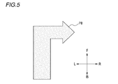
- FIG. 5 is a diagram illustrating a non-reference road surface drawing pattern.
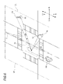
- FIG. 6 is a diagram illustrating the positional relationship between a vehicle and an object.
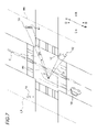
- FIG. 7 is a diagram illustrating the positional relationship between a vehicle and an object.
- FIG. 8 is a diagram illustrating the positional relationship between a vehicle and an object.
- FIG. 9 is a diagram illustrating the positional relationship between a vehicle and an object.
- FIG. 1 is a plan view of a vehicle equipped with a road surface drawing system according to the first embodiment.
- FIG. 2 is a block diagram of the road surface drawing system according to the first embodiment.
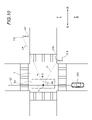
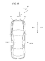
- FIG. 10 is a diagram illustrating the positional relationship between the vehicle and the object when the road surface is viewed from above in the vertical direction.
- FIG. 11 is a plan view of a vehicle equipped with a road surface drawing system according to the second embodiment.
- FIG. 12 is a block diagram of a road surface drawing system according to the second embodiment.
- FIG. 13 is a diagram illustrating the positional relationship between a vehicle and objects near the vehicle.
- FIG. 14 is a diagram illustrating the positional relationship between a vehicle and objects near the vehicle.
- FIG. 15 is a diagram illustrating the positional relationship between a vehicle and objects near the vehicle.
- FIG. 16 is a diagram illustrating the positional relationship between a vehicle and objects near the vehicle.
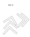
- FIG. 17 is a diagram illustrating a road drawing pattern.
- the terms “horizontal direction”, “vertical direction”, and “front-back direction” may be referred to as appropriate. These directions are relative directions set for vehicle 100 illustrated in FIG. 1 and vehicle 3100 illustrated in FIG.
- the “horizontal direction” is a direction including the “leftward direction” and the “rightward direction”, and is also the vehicle width direction of the vehicle 100 and the vehicle 3100 .
- the “vertical direction” is a direction that includes the “upward direction” and the “downward direction”.
- “Fore-and-aft direction” is a direction that includes "forward direction” and "rearward direction.”
- the front-rear direction is a direction perpendicular to the left-right direction and the up-down direction.
- the symbol U shown in each drawing indicates an upward direction.
- Symbol D indicates the downward direction.
- Symbol F indicates the forward direction.
- Symbol B indicates the rearward direction.
- Symbol L indicates the left direction.
- the symbol R indicates the right direction.
- FIG. 1 is a plan view of a vehicle 100 equipped with a road surface drawing system 1 according to this embodiment.
- Vehicle 100 is, for example, a vehicle (automobile) that can run in manual operation mode or automatic operation mode.
- the road surface drawing system 1 includes a vehicle lamp 10 (an example of a road surface drawing device, and hereinafter also referred to as "lamp 10").
- the lamp 10 draws an image (road surface drawing pattern) indicating predetermined information on the road surface by irradiating the road surface with light.
- the lamps 10 are mounted, for example, on headlamps mounted on the left and right sides of the front of the vehicle 100 .
- the arrangement location and configuration of the lamp 10 are not particularly limited.
- the lamp 10 may be mounted on a tail lamp, a back lamp, or the like mounted on the rear portion of the vehicle 100 .
- the lamp 10 may be mounted on the vehicle 100 alone. Further, for example, the lamp 10 may be arranged on the roof 100A.
- the lamp 10 is configured to draw information indicating the operation of the vehicle 100 on the road surface.
- the information indicating the operation of the vehicle 100 is, for example, information regarding the traveling direction of the own vehicle.
- the lamp 10 irradiates the road surface drawing pattern P on the road surface in front of the vehicle 100 in order to present the right turn of the vehicle 100 to the outside.
- the road surface drawing pattern P is, for example, a figure obtained by combining a substantially rectangular figure elongated in a direction away from the lamp 10 and an arrow figure.
- the drawing method of the lamp 10 is not particularly limited, and for example, a projection method or a scanning method may be adopted.
- the road surface drawing system 1 includes a detection unit 2 , a vehicle control unit 3 , and a lamp 10 including a lighting control unit 12 .
- the detection unit 2 includes a camera 21 and a radar 22.
- the camera 21 is, for example, a camera including an imaging device such as a CCD (Charge-Coupled Device) or CMOS (Complementary MOS).
- the radar 22 is a millimeter wave radar, microwave radar, laser radar, or the like.
- the camera 21 and the radar 22 are configured to detect the surrounding environment of the vehicle 100 (other vehicles, pedestrians, road shape, traffic signs, obstacles, etc.) and output the surrounding environment information to the vehicle control unit 3. .
- the radar 22 may be configured to be able to receive radio waves transmitted from other communication devices.
- the vehicle control unit 3 is configured to control travel of the vehicle 100.
- the vehicle control section 3 is configured by an electronic control unit (ECU).
- the electronic control unit includes a processor such as a CPU (Central Processing Unit), a ROM (Read Only Memory) storing various vehicle control programs, and a RAM (Random Access Memory) temporarily storing various vehicle control data. , is composed of
- the processor develops on the RAM a program specified from various vehicle control programs stored in the ROM, and cooperates with the RAM to execute various processes.
- the vehicle control unit 3 also outputs the surrounding environment information received from the detection unit 2 and the planned route information regarding the route on which the vehicle 100 is about to travel to the illumination control unit 12 .
- the lighting device 10 includes a road surface rendering unit 11 , a lighting control unit 12 and an object processing unit 15 .
- the road surface drawing unit 11 is, for example, a laser scanning device that includes a laser light source and an optical deflection device that deflects the laser light emitted from the laser light source.
- the optical deflection device is, for example, a movable mirror such as a MEMS (Micro Electro Mechanical Systems) mirror or a galvanomirror.
- the road surface drawing unit 11 is configured to irradiate the road surface drawing pattern P on the road surface around the vehicle 100 by scanning laser light.
- the road surface rendering unit 11 may be configured to include a light source and a projection lens configured to irradiate the road surface around the vehicle 100 with light emitted from the light source.
- the light source is composed of, for example, an LED (Light Emitting Diode) element or an LD (Laser Diode) element.
- the road surface drawing unit 11 can irradiate the road surface drawing pattern P onto the road surface around the vehicle 100 .
- the lighting control unit 12 is configured by, for example, an electronic control unit (ECU).
- the lighting control section 12 is configured to control the road surface rendering section 11 .
- the illumination control unit 12 is configured, for example, to control ON/OFF of the light emitted from the light source provided in the road surface drawing unit 11 and the luminous intensity of the light emitted from the light source.
- the lighting control unit 12 outputs the surrounding environment information received from the vehicle control unit 3 to the object processing unit 15 .
- the object processing unit 15 includes an object identification unit 13, an angle calculation unit 14, and an object direction calculation unit 16, and is composed of, for example, one or more electronic control units (ECUs).
- ECUs electronice control units
- the object identification unit 13 identifies objects such as other vehicles and pedestrians based on the surrounding environment information, and generates object information about the identified objects.
- the object is, for example, a person at a position where the road surface drawing pattern P can be visually recognized, a person related to the information indicated by the road surface drawing pattern P, a person within a predetermined distance from the lamp 10, or the like. Note that the predetermined distance is, for example, approximately 5 to 30 m.
- the object information includes position information of the object and the like.
- the generated object information is transmitted to the illumination control unit 12 , the angle calculation unit 14 and the object direction calculation unit 16 .
- the angle calculation unit 14 calculates a first point, which is an arbitrary point on the road surface onto which the road surface drawing unit 11 irradiates the road surface drawing pattern P, and a second point, which is an arbitrary point on the target object specified by the target object specifying unit 13. , and is configured to calculate the solid angle formed by .
- the second point is determined, for example, based on the eyes, head, etc. of a pedestrian, vehicle driver, or the like.
- Solid angle information about the calculated solid angle is transmitted to the illumination control unit 12 .
- the object direction calculator 16 is configured to calculate the traveling direction of the object based on the object information received from the object identifying unit 13 .
- the object direction calculation unit 16 determines a change in the position of the object based on the object information generated continuously in time, and calculates the traveling direction of the object from the change in the position of the object. do.
- Object traveling direction information regarding the calculated traveling direction of the object is transmitted to the illumination control unit 12 .
- FIG. 3 is a diagram illustrating the positional relationship between the vehicle 100 and an object.
- FIG. 4 is a diagram illustrating a reference road drawing pattern PA.
- FIG. 5 is a diagram illustrating a non-reference road drawing pattern PB.
- vehicle 100 is about to make a right turn at intersection I; Therefore, the vehicle control unit 3 transmits a right turn signal indicating that the vehicle 100 is about to turn right to the lighting control unit 12 of the lamp 10 .
- the lamp 10 irradiates the road surface drawing pattern P onto the region R1 in front of the vehicle 100 in order to indicate to the outside that the vehicle 100 is turning right.
- the region R1 is assumed to be substantially rectangular.
- the shape of region R1 is not limited to a substantially rectangular shape.
- the intersection of the diagonal lines of the region R1 is the point X (an example of the first point).
- the detection unit 2 detects a pedestrian A1 existing in the right front direction of the vehicle 100, and outputs surrounding environment information to the vehicle control unit 3 based on the detection result.
- the vehicle control unit 3 transmits the received surrounding environment information to the lighting control unit 12 .
- the lighting control unit 12 transmits the surrounding environment information to the object identification unit 13.
- the object identification unit 13 identifies the pedestrian A1 based on the surrounding environment information. After identifying the pedestrian A1, the object identification unit 13 generates object information including position information such as a point Y1 (an example of a second point) corresponding to the position of the eyes of the pedestrian A1, and obtains the object information. is sent to the angle calculator 14 .
- the angle calculation unit 14 calculates a solid angle ⁇ 1 formed by the point X and the point Y1, and generates solid angle information. Based on the object information generated by the object identification unit 13, the angle calculation unit 14 calculates the solid angle ⁇ 1 Calculate The angle between the line L1 extending on the road surface and the line L2 extending in the height direction of the pedestrian A1 is 90 degrees. In this embodiment, the solid angle ⁇ 1 is 15 degrees. The angle calculator 14 transmits the solid angle ⁇ 1 to the illumination controller 12 .
- the lighting control unit 12 controls the road surface drawing unit 11 based on the solid angle ⁇ 1.
- the illumination control unit 12 controls the road surface drawing unit 11 to draw the reference road surface drawing pattern PA when the solid angle is 10 degrees (an example of a predetermined value) or more.
- the reference road surface drawing pattern is a road surface drawing pattern in a reference state.
- the illumination control unit 12 changes the road surface drawing pattern P from the reference road surface drawing pattern PA to a non-reference road surface drawing pattern different from the reference road surface drawing pattern PA.
- the road surface drawing unit 11 is controlled so as to change to PB.
- the solid angle ⁇ 1 is 15 degrees, so the illumination control unit 12 controls the road surface drawing unit 11 to draw the reference road surface drawing pattern PA illustrated in FIG.
- the object identification unit 13 identifies the pedestrian a1 based on the newly received surrounding environment information. After identifying the pedestrian a1, the object identification unit 13 generates object information including position information such as a point y1 (an example of a second point) corresponding to the position of the eyes of the pedestrian a1, and obtains the object information is sent to the angle calculator 14 .
- the angle calculator 14 calculates a solid angle ⁇ 2 formed by the point X and the point y1, and generates solid angle information. The generated solid angle information is transmitted to the illumination control unit 12 .
- the illumination control unit 12 controls the road surface drawing unit 11 to change the road surface drawing pattern P from the reference road surface drawing pattern PA illustrated in FIG. 4 to the non-reference road surface drawing pattern PB illustrated in FIG.
- the length of the reference road surface drawing pattern PA in the front-rear direction and the length of the non-reference road surface drawing pattern PB in the front-rear direction are equal.
- the non-reference road surface drawing pattern PB is longer in the horizontal direction than the reference road surface drawing pattern PA. Therefore, even if the pedestrian is at a position where the road surface drawing pattern P is crushed and is likely to be visually recognized, the non-reference road surface drawing pattern PB has a length in the left-right direction that is greater than the length in the left-right direction of the reference road surface drawing pattern PA. is long, the shape of the road drawing pattern P can be visually recognized correctly.
- the road surface drawing pattern P can be changed according to the solid angle formed by the road surface drawing pattern P and an object such as the pedestrian A1. Therefore, for example, even when the solid angle formed by the road surface drawing pattern P and the object is small, the visibility of the road surface drawing pattern P is less likely to deteriorate.
- the reference road surface drawing pattern PA is drawn when the solid angle is equal to or greater than the predetermined value, whereas the reference road surface drawing pattern PA is drawn when the solid angle is less than the predetermined value.
- a non-reference road surface drawing pattern PB changed from PA is drawn. Therefore, according to the vehicular lamp 10, even if the road surface drawing pattern P is easily visible when the road surface drawing pattern P is collapsed and the solid angle formed by the road surface drawing pattern P and the object such as the pedestrian A1 is small, the road surface drawing pattern P visibility is less likely to decrease.
- FIG. 6 is a diagram illustrating the positional relationship between the vehicle 100 and an object. As illustrated in FIG. 6, in this embodiment, there are pedestrians A2 and A3 on the front right side of the vehicle 100 . In other words, the pedestrian A2 and the pedestrian A3 are present in the right area RR located to the right of the center line C of the road surface on which the road surface drawing pattern P is drawn.
- the lighting control unit 12 controls the point X and an arbitrary point on the object farthest from the point X when the object exists only in either one of the right region RR and the left region LR. If the solid angle formed by a certain second point is less than 10 degrees, the illumination control unit 12 changes the road surface drawing pattern P from the reference road surface drawing pattern PA to the non-reference road surface drawing pattern PB. On the other hand, if the object exists in the right area RR and the left area LR, or if the solid angle is 10 degrees or more, the illumination control unit 12 changes the road surface drawing pattern P from the reference road surface drawing pattern PA. don't let
- the detection unit 2 detects pedestrians A2 and A3 existing around the vehicle 100 and outputs surrounding environment information to the vehicle control unit 3 based on the detection results.
- the vehicle control unit 3 transmits the received surrounding environment information to the lighting control unit 12 .
- the illumination control unit 12 transmits the received surrounding environment information to the object identification unit 13 .
- the object identification unit 13 identifies the pedestrian A2 and the pedestrian A3 based on the surrounding environment information. After identifying the pedestrian A2 and the pedestrian A3, the object identification unit 13 transmits the object information of the pedestrian A2 and the pedestrian A3 to the lighting control unit 12 and the angle calculation unit 14, respectively.
- the lighting control unit 12 determines that the pedestrian A2 and the pedestrian A3 are present in the right area RR and that no pedestrian is present in the left area LR. It is determined that a plurality of pedestrians (objects) exist only in the right area RR. Based on the determination, the illumination control unit 12 controls the angle calculation unit 14 to calculate the solid angle ⁇ 3 and the solid angle ⁇ 4.
- the angle calculation unit 14 calculates a solid angle ⁇ 3 between the point X and the point Y2 (an example of the second point) corresponding to the eye position of the pedestrian A2.
- the angle calculator 14 also calculates a solid angle ⁇ 4 between the point X and the point Y3 (an example of the second point) corresponding to the eye position of the pedestrian A3.
- the angle calculation unit 14 generates solid angle information corresponding to the solid angles ⁇ 3 and ⁇ 4, respectively, and transmits the generated solid angle information to the illumination control unit 12 .
- the solid angle ⁇ 3 is 15 degrees and the solid angle ⁇ 4 is 5 degrees. control the unit 11; Since the solid angle ⁇ 4 is less than 10 degrees, the illumination control section 12 changes the road surface drawing pattern P from the reference road surface drawing pattern PA to the non-reference road surface drawing pattern PB.
- the angle calculation unit 14 may calculate only the solid angle ⁇ 4 for the pedestrian A3 who is the farthest from the point X among the plurality of pedestrians (objects). That is, the angle calculator 14 may calculate only the solid angle ⁇ 4 without calculating the solid angle ⁇ 3.
- the lighting control is performed according to the solid angle.
- the unit 12 changes the road drawing pattern P. FIG. Therefore, according to the vehicle lamp 10, the road drawing pattern P that is easily visible to all objects is drawn.
- the road surface drawing pattern P is changed according to the solid angle of the object farthest from the road surface drawing pattern P. Therefore, according to the vehicular lamp 10, it is possible to draw a road surface drawing pattern P that is easily visible even to an object that is visually recognized as the road surface drawing pattern P is crushed.
- FIG. 7 is a diagram illustrating the positional relationship between vehicle 100 and an object.
- pedestrians A2 and A3 are in the right front direction of the vehicle 100
- pedestrian A4 is in the left front direction of the vehicle 100.
- the pedestrian A2 and the pedestrian A3 exist in the right area RR
- the pedestrian A4 exists in the left area LR.
- Pedestrian A3 is farther from point X and vehicle 100 than pedestrians A2 and A4.
- the lighting control unit 12 draws the road surface drawing pattern P toward the area where more objects are present, out of the left area LR and the right area RR.
- the road surface rendering unit 11 is controlled as follows. In this case, if at least one of the solid angles formed by the point X and the second point, which is an arbitrary point on each object existing in the area where more objects exist, is less than 10 degrees, lighting control The unit 12 changes the road surface drawing pattern P from the reference road surface drawing pattern PA to the non-reference road surface drawing pattern PB. On the other hand, when the solid angle is 10 degrees or more, the illumination control unit 12 does not change the road surface drawing pattern P from the reference road surface drawing pattern PA.
- the detection unit 2 detects pedestrians A2, A3, and A4 existing around the vehicle 100, and outputs surrounding environment information based on the detection results to the vehicle control unit 3.
- the vehicle control unit 3 transmits the received surrounding environment information to the lighting control unit 12 .
- the illumination control unit 12 transmits the received surrounding environment information to the object identification unit 13 .
- the object identification unit 13 identifies pedestrians A2, A3, and A4 based on the surrounding environment information. After identifying the pedestrian A2, the pedestrian A3, and the pedestrian A4, the object identification unit 13 transmits the object information of each of the pedestrian A2, the pedestrian A3, and the pedestrian A4 to the lighting control unit 12 and the angle calculation unit 14. Send.
- the lighting control unit 12 determines that the pedestrian A2 and the pedestrian A3 are present in the right area RR, and the pedestrian A4 is present in the left area LR. . Based on this determination, the illumination control unit 12 determines that more pedestrians are present in the right area RR than in the left area LR. Based on the determination, the illumination control unit 12 controls the angle calculation unit 14 to calculate the solid angle ⁇ 3 and the solid angle ⁇ 4.
- the angle calculation unit 14 calculates a solid angle ⁇ 3 and a solid angle ⁇ 4 and transmits them to the lighting control unit 12 .
- the specific angles of the solid angle ⁇ 3 and the solid angle ⁇ 4 in this example are the same as the solid angle ⁇ 3 and the solid angle ⁇ 4 in the second example of the first embodiment.
- the illumination control unit 12 controls the road surface rendering unit 11 using the smallest solid angle ⁇ 4 of the solid angles ⁇ 3 and ⁇ 4. Therefore, the illumination control unit 12 changes the road surface drawing pattern P from the reference road surface drawing pattern PA to the non-reference road surface drawing pattern PB.
- the angle calculator 14 calculates only the solid angle ⁇ 4 for the pedestrian A3 who is the farthest from the point X among the plurality of pedestrians (objects) in the area where more objects are present. may That is, the angle calculator 14 may calculate only the solid angle ⁇ 4 without calculating the solid angle ⁇ 3.
- the road surface drawing pattern P is such that the objects in the left area LR and the right area RR where more objects are present are visually recognized. rendered in a way that is easy to Therefore, according to the vehicle lamp 10, the road drawing pattern P that is easily visible to many objects is drawn.
- FIG. 8 is a diagram illustrating the positional relationship between vehicle 100 and an object. As illustrated in FIG. 8 , in this embodiment, there are pedestrians A5 and A6 on the front right side of the vehicle 100 . Pedestrian A5 is taller than pedestrian A6.
- the detection unit 2 detects pedestrians A5 and A6 existing around the vehicle 100 and outputs surrounding environment information to the vehicle control unit 3 based on the detection results.
- the vehicle control unit 3 transmits the received surrounding environment information to the lighting control unit 12 .
- the illumination control unit 12 transmits the received surrounding environment information to the object identification unit 13 .
- the object identifying unit 13 identifies pedestrians A5 and A6 based on the surrounding environment information. After identifying the pedestrian A5 and the pedestrian A6, the object identification unit 13 transmits the object information about the pedestrian A5 and the pedestrian A6 to the illumination control unit 12 and the angle calculation unit 14 .
- the angle calculation unit 14 calculates a solid angle ⁇ 5 between the point X and the point Y5 (an example of the second point) corresponding to the eye position of the pedestrian A5.
- the angle calculator 14 calculates a solid angle ⁇ 6 between the point X and the point Y6 (an example of the second point) corresponding to the eye position of the pedestrian A6.
- the angle calculator 14 generates solid angle information corresponding to the solid angles ⁇ 5 and ⁇ 6, respectively, and transmits the generated solid angle information to the illumination controller 12 .
- the solid angle increases as the pedestrian is taller. Therefore, the solid angle ⁇ 5 is greater than the solid angle ⁇ 6. In this embodiment, the solid angle ⁇ 5 is 15 degrees and the solid angle ⁇ 6 is 5 degrees. control the unit 11; Since the solid angle ⁇ 6 is less than 10 degrees, the illumination control section 12 changes the road surface drawing pattern P from the reference road surface drawing pattern PA to the non-reference road surface drawing pattern PB.
- the angle calculation unit 14 may calculate only the solid angle ⁇ 6 for the shortest pedestrian A6 among the plurality of pedestrians (objects). That is, the angle calculator 14 may calculate only the solid angle ⁇ 6 without calculating the solid angle ⁇ 5.
- the illumination control unit 12 changes the road surface drawing pattern P according to the object whose height is the lowest. It is possible to draw a road surface drawing pattern P that is very easy to visually recognize.
- FIG. 9 is a diagram illustrating the positional relationship between vehicle 100 and an object. As illustrated in FIG. 9 , in this embodiment, there are pedestrians A7, A8, and A9 in the front right direction of the vehicle 100 . Pedestrian A7, pedestrian A8, and pedestrian A9 are closer to vehicle 100 in this order. Pedestrian A7 is moving away from vehicle 100 (rightward in FIG. 9), and pedestrians A8 and A9 are moving closer to vehicle 100 (leftward in FIG. 9).
- the detection unit 2 detects pedestrians A7, A8, and A9 existing around the vehicle 100, and outputs surrounding environment information to the vehicle control unit 3 based on the detection results.
- the vehicle control unit 3 transmits the received surrounding environment information to the lighting control unit 12 .
- the illumination control unit 12 transmits the received surrounding environment information to the object identification unit 13 .
- the object identification unit 13 identifies pedestrians A7, A8, and A9 based on the surrounding environment information. After identifying the pedestrian A7, the pedestrian A8, and the pedestrian A9, the object identification unit 13 transmits the object information of the pedestrian A7, the pedestrian A8, and the pedestrian A9 to the illumination control unit 12, the angle calculation unit 14, and the object. It is transmitted to the direction calculation unit 16 .
- the object direction calculation unit 16 calculates the traveling directions of the pedestrian A7, the pedestrian A8, and the pedestrian A9. In this embodiment, the object direction calculation unit 16 determines that the pedestrian A7 is moving away from the vehicle 100 (to the right in FIG. 9), and that the pedestrians A8 and A9 are moving toward the vehicle 100 (to the right in FIG. 9). to the left). The object direction calculation unit 16 transmits to the lighting control unit 12 object traveling direction information regarding the traveling directions of the pedestrian A7, the pedestrian A8, and the pedestrian A9.
- the lighting control unit 12 receives the planned route information from the vehicle control unit 3.
- the vehicle 100 is about to turn right at the intersection I, so the planned course information in this embodiment is information that the vehicle 100 will go straight until the intersection I and then turn right at the intersection I.
- the lighting control unit 12 identifies a pedestrian entering the planned route of the vehicle 100 based on the planned route information and the object traveling direction information.
- the pedestrian A8 and the pedestrian A9 are identified as pedestrians entering the planned route of the vehicle 100 .
- the lighting control unit 12 determines a point X, a point Y8 (an example of a second point) corresponding to the eye position of the pedestrian A8,
- the angle calculation unit 14 is configured to calculate a solid angle ⁇ 7 formed by, a point X, a point Y9 (an example of a second point) corresponding to the eye position of the pedestrian A9, and a solid angle ⁇ 8 formed by Control.
- the angle calculator 14 calculates a solid angle ⁇ 7 and a solid angle ⁇ 8.
- the solid angle ⁇ 7 is 15 degrees and the solid angle ⁇ 8 is 5 degrees.
- the angle calculation unit 14 may calculate only the solid angle ⁇ 8 for the pedestrian A9 who is the farthest from the point X among the plurality of pedestrians (objects) entering the planned course of the vehicle 100. That is, the angle calculator 14 may calculate only the solid angle ⁇ 8 without calculating the solid angle ⁇ 7.
- the illumination control unit 12 uses the solid angle ⁇ 8 for the pedestrian A9 entering the planned route of the vehicle 100 to convert the road surface drawing pattern P from the reference road surface drawing pattern PA.
- the road surface drawing unit 11 is controlled to change to the non-reference road surface drawing pattern PB. Therefore, according to the vehicular lamp 10, the visibility of the road surface drawing pattern P to an object for which it is highly necessary to make the road surface drawing pattern P visible can be enhanced.
- the illumination control unit 12 uses the solid angle ⁇ 8 for the pedestrian A9 who is farthest from the point X among the plurality of pedestrians entering the planned course of the vehicle 100. Then, the road surface drawing unit 11 is controlled to change the road surface drawing pattern P from the reference road surface drawing pattern PA to the non-reference road surface drawing pattern PB. Therefore, according to the vehicular lamp 10, it is possible to draw the easily visible road surface drawing pattern P even for an object on which the road surface drawing pattern P is difficult to visually recognize.
- FIG. 10 is a diagram illustrating the positional relationship between the vehicle 100 and the object when the road surface is viewed from above in the vertical direction. As illustrated in FIG. 10, in this embodiment, there are pedestrians A10 and A11 on the front right side of the vehicle 100 . Pedestrian A10 is closer to vehicle 100 than pedestrian A11.
- the detection unit 2 detects pedestrians A10 and A11 existing around the vehicle 100 and outputs surrounding environment information to the vehicle control unit 3 based on the detection results.
- the vehicle control unit 3 transmits the received surrounding environment information to the lighting control unit 12 .
- the illumination control unit 12 transmits the received surrounding environment information to the object identification unit 13 .
- the object identifying unit 13 identifies the pedestrian A10 and the pedestrian A11 based on the surrounding environment information. After identifying the pedestrian A10 and the pedestrian A11, the object identification unit 13 transmits the object information of the pedestrian A10 and the pedestrian A11 to the lighting control unit 12 and the angle calculation unit .
- the angle calculation unit 14 converts the position information of the object into position information on the coordinates of the horizontal plane, and converts the point X when the road surface is viewed from above in the vertical direction and the point Y10 corresponding to the eye position of the pedestrian A10.
- a horizontal angle ⁇ 10 formed by the straight line L4 connecting the point Y11 (an example of the second point) corresponding to the eye position and the straight line L5 is calculated.
- the angle calculator 14 transmits the calculated horizontal angle ⁇ 10 to the illumination controller 12 .
- the horizontal angle ⁇ 9 is 60 degrees and the horizontal angle ⁇ 10 is 120 degrees. That is, the horizontal angle ⁇ 10 is greater than the horizontal angle ⁇ 9. Also, the larger the horizontal angle, the more easily the road surface drawing pattern P is obscured from the object and visually recognized. Therefore, it is easier for the pedestrian A11 to visually recognize the crushed road surface drawing pattern P than for the pedestrian A10. Therefore, in this embodiment, the illumination control unit 12 changes the road drawing pattern P based on not only the solid angle but also the horizontal angle ⁇ 10. For example, when the horizontal angle is equal to or greater than a predetermined threshold value, the predetermined value of the solid angle for changing the road drawing pattern P is increased, and the illumination control unit 12 draws the road surface according to the increased predetermined value of the solid angle. control the unit 11;
- the lighting control unit 12 changes the road surface drawing pattern P based on the solid angle and the horizontal angle ⁇ 10, so that the road surface drawing pattern P can be changed more appropriately.
- FIG. 11 is a plan view of a vehicle 3100 equipped with the road surface rendering system 31 according to this embodiment.
- Vehicle 3100 is, for example, a vehicle (automobile) that can run in manual operation mode or automatic operation mode.
- the road surface drawing system 31 includes a vehicle lamp 310 (an example of a road surface drawing device, hereinafter also referred to as "lamp 310").
- the lamp 310 draws an image (road surface drawing pattern) indicating predetermined information on the road surface by irradiating the road surface with light.
- the lamps 310 are mounted, for example, on headlamps mounted on the left and right sides of the front of the vehicle 3100 .
- the arrangement location and configuration of the lamp 310 are not particularly limited.
- the lamp 310 may be mounted on a tail lamp, a back lamp, or the like mounted on the rear portion of the vehicle 3100 .
- the lamp 310 may be mounted on the vehicle 3100 alone. Also, for example, the lamp 310 may be arranged on the roof 3100A.
- the lamp 310 is configured to draw information indicating the operation of the vehicle 3100 on the road surface.
- the information indicating the operation of the vehicle 3100 is, for example, information regarding the traveling direction of the own vehicle.
- the lamp 310 illuminates the road surface in front of the vehicle 3100 with the road surface drawing pattern PT in order to present the right turn of the vehicle 3100 to the outside.
- the road drawing pattern PT is, for example, a figure obtained by combining a substantially rectangular figure elongated in a direction away from the lamp 310 and an arrow figure.
- the drawing method of the lamp 310 is not particularly limited, and for example, a projection method or a scanning method may be adopted.
- the road surface drawing system 31 includes a detection unit 32 , a vehicle control unit 33 , and a lamp 310 including a lighting control unit 312 .
- the detection unit 32 includes a camera 321 and a radar 322.
- the camera 321 may have the same configuration as the camera 21 according to the first embodiment.
- the radar 322 may have the same configuration as the radar 22 according to the first embodiment.
- the vehicle control unit 33 is configured to control travel of the vehicle 3100 .
- the vehicle control unit 33 may have the same hardware configuration as the vehicle control unit 3 according to the first embodiment.
- the vehicle control unit 33 outputs the surrounding environment information received from the detection unit 32 to the lighting control unit 312 .
- the lighting fixture 310 includes a road surface rendering section 311 , a lighting control section 312 and an object processing section 315 .
- the road surface drawing unit 311 may have the same configuration as the road surface drawing unit 11 according to the first embodiment.
- the road surface drawing unit 311 is configured to irradiate the road surface around the vehicle 3100 with the road surface drawing pattern PT by scanning laser light.
- the road surface rendering unit 311 may be configured to include a light source and a projection lens configured to irradiate the road surface around the vehicle 3100 with light emitted from the light source.
- the light source is composed of, for example, an LED (Light Emitting Diode) element or an LD (Laser Diode) element.
- the road surface drawing unit 311 can irradiate the road surface drawing pattern PT onto the road surface around the vehicle 3100 .
- the lighting control unit 312 may have the same configuration as the lighting control unit 12 according to the first embodiment.
- the illumination control unit 312 outputs the surrounding environment information received from the vehicle control unit 33 to the object processing unit 315 .
- the object processing unit 315 includes an object identifying unit 313 and a distance calculating unit 314, and is configured by, for example, one or more electronic control units (ECUs).
- ECUs electronice control units
- the object identification unit 313 identifies objects such as other vehicles and pedestrians based on the surrounding environment information, and generates object information about the identified objects.
- the object is, for example, a person at a position where the road surface drawing pattern PT can be visually recognized, a person related to information indicated by the road surface drawing pattern PT, a person within a predetermined distance from the lamp 310, or the like.
- the predetermined distance is, for example, approximately 5 to 30 m.
- the object information includes position information of the object and the like.
- the generated target object information is transmitted to the distance calculation unit 314 .
- the distance calculation unit 314 calculates a third point, which is an arbitrary point on the road surface to which the road surface drawing unit 311 irradiates the road surface drawing pattern PT, and a fourth point, which is an arbitrary point on the target object specified by the target object specifying unit 313. , is configured to calculate the distance between .
- the fourth point is determined, for example, based on the eyes, head, etc. of pedestrians, vehicle drivers, and the like. Distance information regarding the calculated distance is transmitted to the illumination control unit 312 .
- FIG. 13 and 14 are diagrams illustrating the positional relationship between the vehicle 3100 and objects near the vehicle 3100.
- vehicle 3100 is about to turn right at intersection IA. Therefore, vehicle control unit 33 transmits a right turn signal indicating that vehicle 3100 is about to turn right to illumination control unit 312 of lamp 310 .
- the lamp 310 displays the first road drawing pattern PTA1 (see FIG. 13) according to the first display form or the A region R31 in front of the vehicle 3100 is irradiated with the second road surface drawing pattern PTB1 (see FIG. 14).
- first road surface drawing pattern PTA1 and the second road surface drawing pattern PTB1 in this embodiment are used to convey to objects such as pedestrians that the vehicle 3100 is turning right (an example of a specific meaning).
- the region R31 is assumed to be substantially rectangular.
- the shape of the region R31 is not limited to a substantially rectangular shape.
- the intersection of the diagonal lines of the region R31 is the point X1 (an example of the third point).
- a pedestrian A31 exists on the right side of the vehicle 3100.
- the detection unit 32 detects the pedestrian A31 and outputs surrounding environment information based on the detection result to the vehicle control unit 33 .
- the vehicle control unit 33 transmits the received surrounding environment information to the lighting control unit 312 .
- the lighting control unit 312 transmits the surrounding environment information to the object identification unit 313 .
- the object identification unit 313 identifies the pedestrian A31 based on the surrounding environment information.
- the object identifying unit 313 After identifying the pedestrian A31, the object identifying unit 313 generates object information including position information such as a point Y31 (an example of a fourth point) corresponding to the position of the eyes of the pedestrian A31, and generates the object information is transmitted to the distance calculation unit 314 .
- the distance calculation unit 314 calculates the distance D1 between the point X1 and the point Y31 based on the object information generated by the object identification unit 313, and generates distance information corresponding to the distance D1. In this example, the distance D1 is 7 m.
- the distance calculator 314 transmits the generated distance information to the lighting controller 312 .
- the lighting control unit 312 controls the road surface drawing unit 311 based on the distance information received from the distance calculation unit 314 .
- the illumination control unit 312 controls the road surface drawing unit 311 to draw the first road surface drawing pattern PTA1 when the distance corresponding to the distance information is less than 10 m (an example of the predetermined distance).
- the illumination control unit 312 controls the road surface drawing unit 311 to draw the second road surface drawing pattern PTB1.
- the distance D1 is 7 m. Therefore, the illumination control unit 312 controls the road surface drawing unit 311 to draw the first road surface drawing pattern PTA1.
- the first road surface drawing pattern PTA1 is a figure (hereinafter referred to as (referred to as the first figure). Therefore, the first figure includes an element indicating the traveling direction of vehicle 3100, that is, the right direction. Also, the first figure is substantially L-shaped and has a bent portion 320 . Note that the first graphic is continuously lit in the area R31 for a predetermined time before the right turn operation.
- the detection unit 32 detects pedestrians A31 and A32, and outputs surrounding environment information based on the detection results to the vehicle control unit 33.
- the vehicle control unit 33 transmits the received surrounding environment information to the lighting control unit 12 .
- the lighting control unit 312 transmits the surrounding environment information to the object identification unit 313 .
- the object identification unit 313 identifies the pedestrian A31 and the pedestrian A32 based on the surrounding environment information. After identifying the pedestrian A31 and the pedestrian A32, the object identifying unit 313 identifies a point Y31 corresponding to the eye position of the pedestrian A31 and a point Y32 corresponding to the eye position of the pedestrian A32 (an example of the fourth point). and the like, and transmits the target object information to the distance calculation unit 314 .
- Distance calculation unit 314 calculates distance D1 and distance D2 between point X1 and point Y32 based on the object information generated by object identification unit 313, and obtains distance information corresponding to distance D1 and distance D2. respectively.
- the distance D2 is 12 m.
- the distance calculator 314 transmits the generated distance information to the lighting controller 12 .
- the lighting control unit 312 controls the road surface drawing unit 311 based on the distance information corresponding to the longest distance among the distance information received from the distance calculation unit 314 .
- the distance D2 is 12 m, which is longer than the distance D1, so the illumination control section 312 controls the road surface drawing section 311 based on the distance information corresponding to the distance D2. Therefore, the illumination control unit 312 controls the road surface drawing unit 311 to draw the second road surface drawing pattern PTB1.
- the second road surface drawing pattern PTB1 is a substantially rectangular simple figure (hereinafter referred to as a second figure) that is more simplified than the first road surface drawing pattern PTA1.
- the second graphic is a rectangular graphic that faces the area where vehicle 3100 travels (the area on the front right side in FIG. 13). Note that the second graphic is continuously lit in the region R31 for a predetermined time before the right turn operation.
- the distance D2 is equal to or greater than the predetermined distance, so the pedestrian A32 (the object object) is difficult to convey that the vehicle 3100 is turning right in the first road surface drawing pattern PTA1. ), the fact that the vehicle 3100 is to turn right can be transmitted by the second road surface drawing pattern PTB1. Therefore, according to the vehicle lamp 310 and the road surface drawing system 31, it is possible to notify the pedestrian A32 in the distance that the vehicle 3100 is turning right.
- the figure is simplified more than the first figure.
- a second road surface drawing pattern PTB1 is drawn with a second figure. Since the simplified graphic is easily visible to the pedestrian A2, even if the distance D2 is equal to or greater than the predetermined distance, the pedestrian A2 can recognize that the vehicle 100 is turning right from the simplified graphic. can.
- the shape of the arrow may be easily crushed and difficult for the pedestrian A32 to visually recognize.
- the second road surface drawing pattern PTB1 which is a rectangle facing the area where the vehicle 3100 moves (the area on the front right side in FIG. 14), is drawn. Also, the pedestrian A32 can recognize that the vehicle 3100 is turning right.
- the first figure includes an element indicating the traveling direction of the vehicle 3100, so that the pedestrian A31 can easily recognize the traveling direction of the vehicle 3100. can.
- the first figure has the bent portion 320, so that the pedestrian A31 can easily recognize the traveling direction (especially the turning direction) of the vehicle 3100. can.
- FIG. 15 is a diagram illustrating the positional relationship between the vehicle 3100 and objects near the vehicle 3100. As shown in FIG. In the situation illustrated in FIG. 15, there is a pedestrian A31 near the vehicle 3100. In the situation illustrated in FIG.
- the processing from when the detection unit 32 in this embodiment outputs the surrounding environment information to the vehicle control unit 33 to when the distance calculation unit 314 transmits the distance information to the lighting control unit 312 is the first example of the second embodiment. Since it is the same as the processing in , the description is omitted.
- the lighting control unit 312 controls the road surface drawing unit 311 based on the distance information received from the distance calculation unit 314. Therefore, the illumination control unit 312 controls the road surface drawing unit 311 to draw the first road surface drawing pattern PTA2.
- the first road surface drawing pattern PTA2 is projected onto the area R31 in a display form of characters "turn right". It should be noted that the first road surface drawing pattern PTA2 is for conveying to objects such as pedestrians that the vehicle 3100 is turning right (an example of a specific meaning).
- the first road surface drawing pattern PTA2 is projected onto the area R31 so that the characters "turn right" are oriented forward when viewed from the pedestrian A31 so that the pedestrian A31 can easily recognize the first road surface drawing pattern PTA2.
- the second road surface drawing pattern is drawn as in the first example of the second embodiment.
- PTB1 is irradiated to region R31.
- the vehicle lamp 310 having the above configuration, when the distance D2 between the point X1 and the pedestrian A32 who is the farthest object from the point X1 is equal to or greater than a predetermined distance, the vehicle 3100 is recognized as turning right rather than the characters.
- the second road surface drawing pattern PTB1 is drawn with a figure that can easily convey to the pedestrian A32 that the road is to be crossed. Therefore, the pedestrian A32 (see FIG. 14) whose distance D2 is a predetermined distance or more and who is difficult to convey that the vehicle 3100 is turning right in the first display mode (in the present embodiment, the display mode is a display mode in which characters "turn right"). , it is also possible to transmit that vehicle 3100 is to turn right.
- FIG. 16 is a diagram illustrating the positional relationship between the vehicle 3100 and objects in the vicinity of the vehicle 3100. As shown in FIG. In the situation illustrated in FIG. 16, there are pedestrians A31 and A32 near the vehicle 3100 .
- the processing from when the detection unit 32 in this embodiment outputs the surrounding environment information to the vehicle control unit 33 to when the distance calculation unit 314 transmits the distance information to the lighting control unit 312 is the first example of the second embodiment. Since it is the same as the processing in , the description is omitted.
- the first road surface drawing pattern PTA1 is projected onto the area R31 as in the first example of the second embodiment. be.
- the illumination control unit 312 calculates the distance information received from the distance calculation unit 314 by The road surface drawing unit 311 is controlled based on the distance information corresponding to the long distance. Therefore, the illumination control unit 312 controls the road surface drawing unit 311 to draw the second road surface drawing pattern PTB2.
- the second road surface drawing pattern PTB2 is for conveying to objects such as pedestrians that the vehicle 3100 is turning right (an example of a specific meaning).
- the second road surface drawing pattern PTB2 has the same shape as the second figure in the first example of the second embodiment, but is not lit continuously for a predetermined time before the right turn. not lit and blinking.
- the blinking is realized by continuously performing ON/OFF control of the road surface drawing unit 311 by the lighting control unit 312 .
- the second road surface drawing pattern PTB2 may blink at regular time intervals or may blink at irregular time intervals.
- the second road surface drawing pattern PTB2 according to the second display mode which is a blinking rectangular figure directed toward the area where the vehicle 3100 travels (the area on the front right side in FIG. 16), is drawn. be done.
- the blinking mode is easier for the pedestrian A32 to recognize than the continuous lighting mode for a predetermined period of time before the right turn. Therefore, vehicle lamp 310 can notify pedestrian A32 that vehicle 3100 is turning right even if distance D2 is greater than or equal to the predetermined distance.
- the lighting control unit 12 is separated from the vehicle control unit 3 in the first embodiment, it may be configured integrally with the vehicle control unit. Further, in the second embodiment, the lighting control section 312 is separated from the vehicle control section 33, but may be configured integrally with the vehicle control section.
- the illumination control unit 12 may implement the functions of the object identification unit 13, the angle calculation unit 14, and the object direction calculation unit 16. Further, in the second embodiment, the illumination control section 312 may implement the functions of the object identification section 313 and the distance calculation section 314 .
- the vehicle control unit 3 may realize the functions of the object identification unit 13, the angle calculation unit 14, and the object direction calculation unit 16. Further, in the second embodiment, the vehicle control unit 33 may implement the functions of the object identification unit 313 and the distance calculation unit 314 .
- the road surface drawing patterns PA and PB illustrated in FIGS. 4 and 5 are drawn on the road surface, but the present disclosure is not limited to this.
- a figure or the like obtained by combining a plurality of arrows having notches as illustrated in FIG. 17 may be drawn on the road surface, or characters or the like may be drawn on the road surface.
- the figure illustrated in FIG. 17 is the reference road surface drawing pattern, and when it is changed to the non-reference road surface drawing pattern, the non-reference road surface drawing pattern is the front-rear direction of the reference road surface drawing pattern illustrated in FIG. It is a figure that is thicker in one of the left and right directions, or that the distance between each figure element is wider.
- the first road surface drawing pattern PTA1 is the road surface drawing pattern illustrated in FIG. 13, but the present disclosure is not limited to this.
- a figure or the like formed by combining a plurality of arrows having notches as illustrated in FIG. 17 may be drawn on the road surface.
- the road surface drawing pattern P is drawn by irradiating the road surface with light from the lamps 10 mounted on the vehicle 100, but the present disclosure is not limited to this.
- the road surface drawing pattern P may be drawn on the road surface by irradiating the road surface with light from infrastructure equipment such as street lights, traffic signals, and marker lights.
- the road surface drawing pattern PT is drawn by irradiating the road surface with light from the lamp 310 mounted on the vehicle 3100, but the present disclosure is not limited to this.
- the road surface drawing pattern PT may be drawn by irradiating the road surface with light from infrastructure equipment such as street lights, traffic signals, and marker lights.
- the object identification unit 13 generates position information such as points corresponding to the positions of the eyes of the pedestrian A1, but the angle calculation unit 14 may generate the position information. Further, in the second embodiment, the object identification unit 313 generates position information such as points corresponding to the positions of the eyes of the pedestrian A31, but the distance calculation unit 314 may generate the position information. .
- the first road surface drawing patterns PTA1-PTA2 and the second road surface drawing patterns PTB1-PTB2 are for transmitting to objects such as pedestrians that the vehicle 3100 is turning right, but the present disclosure is not limited to this.
- the first road surface drawing patterns PTA1-PTA2 and the second road surface drawing patterns PTB1-PTB2 are used, for example, to convey to objects such as pedestrians that the vehicle 3100 stops before the intersection IA (an example of a specific meaning). may be of
- the second display form in the third example of the second embodiment is blinking of a rectangular figure, it may be blinking of a character (for example, the character "Turn right"), an arrow figure, a first figure, or the like.
Landscapes
- Engineering & Computer Science (AREA)
- General Engineering & Computer Science (AREA)
- Mechanical Engineering (AREA)
- Lighting Device Outwards From Vehicle And Optical Signal (AREA)
Abstract
Description
路面に路面描画パターンを照射する路面描画部と、
所定の領域に存在する対象物を検出するように構成された検出部からの周辺環境情報に基づいて、前記対象物を特定する対象物特定部と、
前記路面描画部が前記路面描画パターンを照射する路面における任意の点である第一点と、前記対象物における任意の点である第二点と、のなす立体角度を算出する角度算出部と、
前記路面描画部を制御する照明制御部と、を備え、
前記照明制御部は、前記角度算出部により算出された前記立体角度に応じて前記路面描画パターンを変化させる。
路面に路面描画パターンを照射する路面描画部と、
所定の領域に存在する対象物を検出する検出部と、
前記検出部からの周辺環境情報に基づいて、前記対象物を特定する対象物特定部と、
前記路面描画部が前記路面描画パターンを照射する路面における任意の点である第一点と、前記対象物における任意の点である第二点と、のなす立体角度を算出する角度算出部と、
前記路面描画部を制御する照明制御部と、を備え、
前記照明制御部は、前記角度算出部により算出された前記立体角度に応じて前記路面描画パターンを変化させる。
路面に路面描画パターンを照射する路面描画部と、
所定の領域に存在する対象物を検出するように構成された検出部からの周辺環境情報に基づいて、前記対象物を特定する対象物特定部と、
前記路面描画部が前記路面描画パターンを照射する路面における任意の点である第三点と前記対象物における任意の点である第四点との距離を算出する距離算出部と、
前記路面描画部を制御する照明制御部と、を備え、
前記照明制御部は、
最も遠い対象物における前記距離が所定距離未満の場合、特定の意味を伝達する第一表示形態で前記路面描画パターンを前記路面に照射するように前記路面描画部を制御し、
最も遠い対象物における前記距離が所定距離以上の場合、前記特定の意味を伝達し、前記第一表示形態とは異なる第二表示形態で前記路面描画パターンを前記路面に照射するように前記路面描画部を制御する。
路面に路面描画パターンを照射する路面描画部と、
所定の領域に存在する一以上の対象物を検出する検出部と、
前記検出部からの周辺環境情報に基づいて、前記対象物を特定する対象物特定部と、
前記路面描画部が前記路面描画パターンを照射する路面における任意の点である第三点と前記対象物における任意の点である第四点との距離を算出する距離算出部と、
前記路面描画部を制御する照明制御部と、を備え、
前記照明制御部は、
最も遠い対象物における前記距離が所定距離未満の場合、特定の意味を伝達する第一表示形態で前記路面描画パターンを前記路面に照射するように前記路面描画部を制御し、
最も遠い対象物における前記距離が所定距離以上の場合、前記特定の意味を伝達し、前記第一表示形態とは異なる第二表示形態で前記路面描画パターンを前記路面に照射するように前記路面描画部を制御する。
図1を参照して、本実施形態に係る路面描画システム1を備える車両100について以下に説明する。図1は、本実施形態に係る路面描画システム1を備えた車両100の平面図である。車両100は、例えば、手動運転モードまたは自動運転モードで走行可能な車両(自動車)である。なお、路面描画システム1は、車両用灯具10(路面描画装置の一例であって、以下、「灯具10」ともいう。)を備えている。灯具10は、路面に光を照射することにより、所定の情報を示す画像(路面描画パターン)を路面に描画する。
次に、図3~図5を参照しつつ第一実施形態の第一実施例について説明する。図3は、車両100と対象物との位置関係を例示する図である。図4は、基準路面描画パターンPAを例示する図である。図5は、非基準路面描画パターンPBを例示する図である。本実施例において、車両100は交差点Iにおいて右折しようとしている。このため、車両制御部3は、車両100が右折しようとしていることを示す右折信号を灯具10の照明制御部12に送信する。灯具10は、受信した右折信号に基づいて、車両100の右折を外部に向けて提示するために、路面描画パターンPを、車両100の前方の領域R1に照射する。なお、本実施例では、説明の便宜上、領域R1は略長方形状であるものとして説明する。ただし、領域R1の形状は、略長方形状に限られない。また、本実施例において、領域R1の対角線の交点は、点X(第一点の一例)である。
次に、図6を参照しつつ、第一実施形態の第二実施例について説明する。なお、本実施例の説明において、第一実施形態の第一実施例の説明と重複する部分については、同じ符号を付し、適宜説明を省略する。図6は、車両100と対象物との位置関係を例示する図である。図6に例示するように、本実施例においては、車両100の右前方向に歩行者A2と歩行者A3がいる。つまり、歩行者A2および歩行者A3は、路面描画パターンPが描画される路面の中心線Cに対して右方に位置する右方領域RRに存在する。一方で、路面描画パターンPが描画される路面の中心線Cに対して左方に位置する左方領域LRには歩行者等の対象物は存在しない。なお、歩行者A3は、歩行者A2よりも、点Xおよび車両100から遠い位置にいる。
次に、図7を参照しつつ、第一実施形態の第三実施例について説明する。なお、本実施例の説明において、第一実施形態の第一実施例または第二実施例の説明と重複する部分については、同じ符号を付し、適宜説明を省略する。図7は、車両100と対象物との位置関係を例示する図である。図7に例示するように、本実施例においては、車両100の右前方向に歩行者A2と歩行者A3がおり、車両100の左前方向には歩行者A4がいる。つまり、歩行者A2および歩行者A3は右方領域RRに存在し、歩行者A4は左方領域LRに存在する。なお、歩行者A3は、歩行者A2および歩行者A4よりも、点Xおよび車両100から遠い位置にいる。
次に、図8を参照しつつ、第一実施形態の第四実施例について説明する。なお、本実施例の説明において、第一実施形態の第一実施例~第三実施例の説明と重複する部分については、同じ符号を付し、適宜説明を省略する。図8は、車両100と対象物との位置関係を例示する図である。図8に例示するように、本実施例においては、車両100の右前方向に歩行者A5と歩行者A6がいる。なお、歩行者A5は歩行者A6よりも背が高い。
次に、図9を参照しつつ、第一実施形態の第五実施例について説明する。なお、本実施例の説明において、第一実施形態の第一実施例~第四実施例の説明と重複する部分については、同じ符号を付し、適宜説明を省略する。図9は、車両100と対象物との位置関係を例示する図である。図9に例示するように、本実施例においては、車両100の右前方向に歩行者A7、歩行者A8および歩行者A9がいる。歩行者A7、歩行者A8および歩行者A9は、この順で車両100から近い。また、歩行者A7は車両100から遠ざかる方向(図9における右方向)に進行しており、歩行者A8および歩行者A9は車両100に近づく方向(図9における左方向)に進行している。
次に、図10を参照しつつ、第一実施形態の第六実施例について説明する。なお、本実施例の説明において、第一実施形態の第一実施例~第五実施例の説明と重複する部分については、同じ符号を付し、適宜説明を省略する。図10は、路面を鉛直方向の上方から見たときの車両100と対象物との位置関係を例示する図である。図10に例示するように、本実施例においては、車両100の右前方向に歩行者A10および歩行者A11がいる。歩行者A10は、歩行者A11よりも、車両100に近い位置にいる。
次に、図11を参照して、本実施形態に係る路面描画システム31を備える車両3100について以下に説明する。図11は、本実施形態に係る路面描画システム31を備えた車両3100の平面図である。車両3100は、例えば、手動運転モードまたは自動運転モードで走行可能な車両(自動車)である。なお、路面描画システム31は、車両用灯具310(路面描画装置の一例であって、以下、「灯具310」ともいう。)を備えている。灯具310は、路面に光を照射することにより、所定の情報を示す画像(路面描画パターン)を路面に描画する。
次に、図13および図14を参照しつつ第二実施形態の第一実施例について説明する。図13および図14は、車両3100と車両3100付近にいる対象物との位置関係を例示する図である。本実施例において、車両3100は交差点IAにおいて右折しようとしている。このため、車両制御部33は、車両3100が右折しようとしていることを示す右折信号を灯具310の照明制御部312に送信する。灯具310は、受信した右折信号に基づいて、車両3100の右折を外部に向けて提示するために、第一表示形態に係る第一路面描画パターンPTA1(図13参照)または第二表示形態に係る第二路面描画パターンPTB1(図14参照)を、車両3100の前方の領域R31に照射する。なお、本実施例における第一路面描画パターンPTA1および第二路面描画パターンPTB1は、車両3100が右折すること(特定の意味の一例)を歩行者等の対象物に伝達するためのものである。また、本実施例では、説明の便宜上、領域R31は略長方形状であるものとして説明する。ただし、領域R31の形状は略長方形状に限られない。また、本実施例において、領域R31の対角線の交点は、点X1(第三点の一例)である。
次に、図14および図15を参照しつつ、第二実施形態の第二実施例について説明する。なお、本実施例の説明において、第二実施形態の第一実施例の説明と重複する部分については、同じ符号を付し、適宜説明を省略する。図15は、車両3100と車両3100付近にいる対象物との位置関係を例示する図である。図15に例示する状況において、車両3100の付近には歩行者A31がいる。
次に、図13および図16を参照しつつ、第二実施形態の第三実施例について説明する。なお、本実施例の説明において、第二実施形態の第一実施例の説明と重複する部分については、同じ符号を付し、適宜説明を省略する。図16は、車両3100と車両3100付近にいる対象物との位置関係を例示する図である。図16に例示する状況において、車両3100の付近には歩行者A31および歩行者A32がいる。
Claims (18)
- 路面に路面描画パターンを照射する路面描画部と、
所定の領域に存在する対象物を検出するように構成された検出部からの周辺環境情報に基づいて、前記対象物を特定する対象物特定部と、
前記路面描画部が前記路面描画パターンを照射する路面における任意の点である第一点と、前記対象物における任意の点である第二点と、のなす立体角度を算出する角度算出部と、
前記路面描画部を制御する照明制御部と、を備え、
前記照明制御部は、前記角度算出部により算出された前記立体角度に応じて前記路面描画パターンを変化させる、路面描画装置。 - 前記照明制御部は、
前記立体角度が所定値以上のとき、基準状態の路面描画パターンである基準路面描画パターンを照射するように前記路面描画部を制御し、
前記立体角度が所定値未満のとき、前記路面描画パターンを、前記基準路面描画パターンから変化させるように前記路面描画部を制御する、請求項1に記載の路面描画装置。 - 前記対象物は、複数の対象物を含み、
前記複数の対象物の全てが、前記路面描画パターンを照射する路面の中心線に対して左方に位置する左方領域または右方に位置する右方領域のいずれか一方に存在するとき、前記照明制御部は前記路面描画パターンを変化させ、左方領域および右方領域に前記対象物が存在するとき、前記照明制御部は前記路面描画パターンを変化させない、請求項1または2に記載の路面描画装置。 - 前記対象物は、複数の対象物を含み、
前記対象物が、前記路面描画パターンを照射する路面の中心線に対して左方に位置する左方領域および右方に位置する右方領域に存在するとき、前記照明制御部は、前記左方領域および前記右方領域のうち前記対象物がより多く存在する領域に向けて、前記路面描画パターンを変化させる、請求項1または2に記載の路面描画装置。 - 前記対象物は、複数の対象物を含み、
前記照明制御部は、前記複数の対象物のうち前記第一点から最も遠い対象物に応じて前記路面描画パターンを変化させる、請求項1から4のいずれか一項に記載の路面描画装置。 - 前記対象物は、複数の対象物を含み、
前記照明制御部は、前記複数の対象物のうち高さが最も低い対象物に応じて前記路面描画パターンを変化させる、請求項1から5のいずれか一項に記載の路面描画装置。 - 前記対象物の進行方向を算出する対象物方向算出部と、を有し、
前記照明制御部は、前記路面描画装置が搭載された車両の予定進路と前記対象物の進行方向とに基づき、前記車両の予定進路に進入する前記対象物を特定し、特定した前記対象物に応じて前記路面描画パターンを変化させる、請求項1から6のいずれか一項に記載の路面描画装置。 - 前記対象物は、複数の対象物を含み、
前記複数の対象物が、前記路面描画装置が搭載された車両の予定進路に進入する場合、前記照明制御部は、前記複数の対象物の中で前記車両から最も遠い対象物に応じて前記路面描画パターンを変化させる、請求項1から7のいずれか一項に記載の路面描画装置。 - 前記照明制御部は、前記立体角度に加えて、路面を鉛直方向の上方から見たときの前記第一点と前記第二点を結ぶ直線と前記路面描画装置が搭載された車両の進行方向とのなす水平角度に基づいて、前記路面描画パターンを変化させる、請求項1から8のいずれか一項に記載の路面描画装置。
- 路面に路面描画パターンを照射する路面描画部と、
所定の領域に存在する対象物を検出する検出部と、
前記検出部からの周辺環境情報に基づいて、前記対象物を特定する対象物特定部と、
前記路面描画部が前記路面描画パターンを照射する路面における任意の点である第一点と、前記対象物における任意の点である第二点と、のなす立体角度を算出する角度算出部と、
前記路面描画部を制御する照明制御部と、を備え、
前記照明制御部は、前記角度算出部により算出された前記立体角度に応じて前記路面描画パターンを変化させる、路面描画システム。 - 路面に路面描画パターンを照射する路面描画部と、
所定の領域に存在する対象物を検出するように構成された検出部からの周辺環境情報に基づいて、前記対象物を特定する対象物特定部と、
前記路面描画部が前記路面描画パターンを照射する路面における任意の点である第三点と前記対象物における任意の点である第四点との距離を算出する距離算出部と、
前記路面描画部を制御する照明制御部と、を備え、
前記照明制御部は、
最も遠い対象物における前記距離が所定距離未満の場合、特定の意味を伝達する第一表示形態で前記路面描画パターンを前記路面に照射するように前記路面描画部を制御し、
最も遠い対象物における前記距離が所定距離以上の場合、前記特定の意味を伝達し、前記第一表示形態とは異なる第二表示形態で前記路面描画パターンを前記路面に照射するように前記路面描画部を制御する、路面描画装置。 - 前記第一表示形態は、文字による表示形態であり、
前記第二表示形態は、図形による表示形態である、請求項11に記載の路面描画装置。 - 前記第一表示形態は、第一図形による表示形態であり、
前記第二表示形態は、前記第一図形よりも簡素化された第二図形による表示形態である、請求項11に記載の路面描画装置。 - 前記第一表示形態は、文字または図形を所定時間点灯させた表示形態であり、
前記第二表示形態は、前記文字または前記図形を点滅させた形態である、請求項11に記載の路面描画装置。 - 前記第一表示形態は、前記路面描画装置が搭載された車両から前記車両の進む領域に向かう矢印であり、
前記第二表示形態は、前記車両から前記車両の進む領域に向かう矩形、または、前記矩形の点滅、または、前記矢印の点滅である、請求項11に記載の路面描画装置。 - 前記矢印は、進行方向を示す要素を含む図形である、請求項15に記載の路面描画装置。
- 前記矢印は、屈曲部を有する、請求項15または16に記載の路面描画装置。
- 路面に路面描画パターンを照射する路面描画部と、
所定の領域に存在する一以上の対象物を検出する検出部と、
前記検出部からの周辺環境情報に基づいて、前記対象物を特定する対象物特定部と、
前記路面描画部が前記路面描画パターンを照射する路面における任意の点である第三点と前記対象物における任意の点である第四点との距離を算出する距離算出部と、
前記路面描画部を制御する照明制御部と、を備え、
前記照明制御部は、
最も遠い対象物における前記距離が所定距離未満の場合、特定の意味を伝達する第一表示形態で前記路面描画パターンを前記路面に照射するように前記路面描画部を制御し、
最も遠い対象物における前記距離が所定距離以上の場合、前記特定の意味を伝達し、前記第一表示形態とは異なる第二表示形態で前記路面描画パターンを前記路面に照射するように前記路面描画部を制御する、路面描画システム。
Priority Applications (2)
| Application Number | Priority Date | Filing Date | Title |
|---|---|---|---|
| CN202280022343.0A CN117043010A (zh) | 2021-03-19 | 2022-02-21 | 路面绘制装置以及路面绘制系统 |
| JP2023506898A JP7739410B2 (ja) | 2021-03-19 | 2022-02-21 | 路面描画装置および路面描画システム |
Applications Claiming Priority (4)
| Application Number | Priority Date | Filing Date | Title |
|---|---|---|---|
| JP2021045473 | 2021-03-19 | ||
| JP2021-045474 | 2021-03-19 | ||
| JP2021-045473 | 2021-03-19 | ||
| JP2021045474 | 2021-03-19 |
Publications (1)
| Publication Number | Publication Date |
|---|---|
| WO2022196254A1 true WO2022196254A1 (ja) | 2022-09-22 |
Family
ID=83321237
Family Applications (1)
| Application Number | Title | Priority Date | Filing Date |
|---|---|---|---|
| PCT/JP2022/006920 Ceased WO2022196254A1 (ja) | 2021-03-19 | 2022-02-21 | 路面描画装置および路面描画システム |
Country Status (2)
| Country | Link |
|---|---|
| JP (1) | JP7739410B2 (ja) |
| WO (1) | WO2022196254A1 (ja) |
Citations (3)
| Publication number | Priority date | Publication date | Assignee | Title |
|---|---|---|---|---|
| WO2018092710A1 (ja) * | 2016-11-18 | 2018-05-24 | パナソニックIpマネジメント株式会社 | 通知装置、自動運転車両、通知方法、プログラム、非一時的記録媒体、および通知システム |
| JP2018122755A (ja) * | 2017-02-01 | 2018-08-09 | トヨタ自動車株式会社 | 前照灯制御装置 |
| JP2020037319A (ja) * | 2018-09-04 | 2020-03-12 | 株式会社Jvcケンウッド | 車両用光出力装置、光出力方法、及びプログラム |
Family Cites Families (1)
| Publication number | Priority date | Publication date | Assignee | Title |
|---|---|---|---|---|
| JP6418182B2 (ja) * | 2016-03-07 | 2018-11-07 | トヨタ自動車株式会社 | 車両用照明装置 |
-
2022
- 2022-02-21 WO PCT/JP2022/006920 patent/WO2022196254A1/ja not_active Ceased
- 2022-02-21 JP JP2023506898A patent/JP7739410B2/ja active Active
Patent Citations (3)
| Publication number | Priority date | Publication date | Assignee | Title |
|---|---|---|---|---|
| WO2018092710A1 (ja) * | 2016-11-18 | 2018-05-24 | パナソニックIpマネジメント株式会社 | 通知装置、自動運転車両、通知方法、プログラム、非一時的記録媒体、および通知システム |
| JP2018122755A (ja) * | 2017-02-01 | 2018-08-09 | トヨタ自動車株式会社 | 前照灯制御装置 |
| JP2020037319A (ja) * | 2018-09-04 | 2020-03-12 | 株式会社Jvcケンウッド | 車両用光出力装置、光出力方法、及びプログラム |
Also Published As
| Publication number | Publication date |
|---|---|
| JP7739410B2 (ja) | 2025-09-16 |
| JPWO2022196254A1 (ja) | 2022-09-22 |
Similar Documents
| Publication | Publication Date | Title |
|---|---|---|
| US20230221569A1 (en) | Virtual image display device and display system | |
| US9785042B2 (en) | Vehicular lighting apparatus | |
| US20220219600A1 (en) | Vehicle illumination system, vehicle system, lamp unit and vehicle lamp | |
| JP7241081B2 (ja) | 車両用表示システム及び車両 | |
| US9278646B2 (en) | Driving support apparatus for vehicle | |
| JP7309724B2 (ja) | 車両用表示システム及び車両 | |
| JP7282789B2 (ja) | 車両用表示システム、車両システム及び車両 | |
| US10946787B2 (en) | Motor vehicle comprising a lighting module for generating a set of symbols | |
| JP5976352B2 (ja) | 車両用前照灯の配光制御システム及び車両用前照灯システム | |
| CN210191316U (zh) | 车辆用显示系统以及车辆 | |
| US10730427B2 (en) | Lighting device | |
| US20260034927A1 (en) | Vehicular headlight | |
| CN112770936A (zh) | 灯具系统 | |
| WO2019176418A1 (ja) | 車両用ランプ、車両検出方法及び車両検出装置 | |
| WO2022196254A1 (ja) | 路面描画装置および路面描画システム | |
| EP4434815A1 (en) | Road surface-marking light and road surface-marking light system | |
| EP4570592A1 (en) | Road surface rendering device | |
| KR102823124B1 (ko) | 공사장 운행 시의 차량 조명 조정 방법 및 차량 | |
| CN117043010A (zh) | 路面绘制装置以及路面绘制系统 | |
| JP2022022556A (ja) | 車両用灯具 | |
| JP7781890B2 (ja) | ランプシステム | |
| JP6663770B2 (ja) | 車両の配光制御装置 | |
| CN115402190B (zh) | 远光灯控制方法、装置及计算机可读存储介质 | |
| EP4588720A1 (en) | Vehicle headlight | |
| JP2025187461A (ja) | 画像描画装置 |
Legal Events
| Date | Code | Title | Description |
|---|---|---|---|
| 121 | Ep: the epo has been informed by wipo that ep was designated in this application |
Ref document number: 22771013 Country of ref document: EP Kind code of ref document: A1 |
|
| WWE | Wipo information: entry into national phase |
Ref document number: 2023506898 Country of ref document: JP |
|
| WWE | Wipo information: entry into national phase |
Ref document number: 202280022343.0 Country of ref document: CN |
|
| NENP | Non-entry into the national phase |
Ref country code: DE |
|
| 122 | Ep: pct application non-entry in european phase |
Ref document number: 22771013 Country of ref document: EP Kind code of ref document: A1 |