WO2022196207A1 - マップ画像生成装置、制御方法、及び非一時的なコンピュータ可読媒体 - Google Patents
マップ画像生成装置、制御方法、及び非一時的なコンピュータ可読媒体 Download PDFInfo
- Publication number
- WO2022196207A1 WO2022196207A1 PCT/JP2022/005624 JP2022005624W WO2022196207A1 WO 2022196207 A1 WO2022196207 A1 WO 2022196207A1 JP 2022005624 W JP2022005624 W JP 2022005624W WO 2022196207 A1 WO2022196207 A1 WO 2022196207A1
- Authority
- WO
- WIPO (PCT)
- Prior art keywords
- map image
- physical property
- nodes
- map
- node
- Prior art date
- Legal status (The legal status is an assumption and is not a legal conclusion. Google has not performed a legal analysis and makes no representation as to the accuracy of the status listed.)
- Ceased
Links
Images






Classifications
-
- G—PHYSICS
- G06—COMPUTING OR CALCULATING; COUNTING
- G06F—ELECTRIC DIGITAL DATA PROCESSING
- G06F30/00—Computer-aided design [CAD]
- G06F30/20—Design optimisation, verification or simulation
- G06F30/27—Design optimisation, verification or simulation using machine learning, e.g. artificial intelligence, neural networks, support vector machines [SVM] or training a model
-
- G—PHYSICS
- G06—COMPUTING OR CALCULATING; COUNTING
- G06T—IMAGE DATA PROCESSING OR GENERATION, IN GENERAL
- G06T11/00—Two-dimensional [2D] image generation
- G06T11/10—Texturing; Colouring; Generation of textures or colours
-
- G—PHYSICS
- G06—COMPUTING OR CALCULATING; COUNTING
- G06F—ELECTRIC DIGITAL DATA PROCESSING
- G06F18/00—Pattern recognition
- G06F18/20—Analysing
- G06F18/21—Design or setup of recognition systems or techniques; Extraction of features in feature space; Blind source separation
- G06F18/213—Feature extraction, e.g. by transforming the feature space; Summarisation; Mappings, e.g. subspace methods
- G06F18/2137—Feature extraction, e.g. by transforming the feature space; Summarisation; Mappings, e.g. subspace methods based on criteria of topology preservation, e.g. multidimensional scaling or self-organising maps
-
- G—PHYSICS
- G06—COMPUTING OR CALCULATING; COUNTING
- G06T—IMAGE DATA PROCESSING OR GENERATION, IN GENERAL
- G06T7/00—Image analysis
- G06T7/90—Determination of colour characteristics
-
- G—PHYSICS
- G06—COMPUTING OR CALCULATING; COUNTING
- G06V—IMAGE OR VIDEO RECOGNITION OR UNDERSTANDING
- G06V10/00—Arrangements for image or video recognition or understanding
- G06V10/70—Arrangements for image or video recognition or understanding using pattern recognition or machine learning
- G06V10/762—Arrangements for image or video recognition or understanding using pattern recognition or machine learning using clustering, e.g. of similar faces in social networks
-
- G—PHYSICS
- G06—COMPUTING OR CALCULATING; COUNTING
- G06F—ELECTRIC DIGITAL DATA PROCESSING
- G06F2111/00—Details relating to CAD techniques
- G06F2111/10—Numerical modelling
-
- G—PHYSICS
- G06—COMPUTING OR CALCULATING; COUNTING
- G06F—ELECTRIC DIGITAL DATA PROCESSING
- G06F2113/00—Details relating to the application field
- G06F2113/26—Composites
-
- G—PHYSICS
- G06—COMPUTING OR CALCULATING; COUNTING
- G06T—IMAGE DATA PROCESSING OR GENERATION, IN GENERAL
- G06T2207/00—Indexing scheme for image analysis or image enhancement
- G06T2207/10—Image acquisition modality
- G06T2207/10024—Color image
Definitions
- This disclosure relates to technology for providing information related to product development.
- Patent Literature 1 discloses a system that uses a self-organizing map to support understanding of causal relationships between design values and physical property values of tires.
- Patent Document 1 a self-organizing map is used to identify which of a plurality of tire design variables is an important factor. Therefore, it is not assumed that the self-organizing map will be used for any other purpose.
- the present disclosure is made in view of such problems, and an object of the present disclosure is to provide a new technology that provides useful information for product development.
- the map image generation device of the present disclosure includes, for each of a plurality of patterns of materials that can be used in a target process, material specification information that represents the material specifications of the material, and a product that can be generated in the process using the material.
- an acquisition unit that acquires physical property information indicating physical property amounts for each of a plurality of physical properties of the product;
- a self-organizing map generation unit that generates a self-organizing map in which each node is assigned a physical property vector, and a map image generation unit that generates a map image representing each of the nodes arranged on the map space.
- the map image generation unit uses each of the material specification information to allocate a specification vector indicating a value related to the material specification to each of the nodes, and based on the assignment of the specification vector to each of the nodes, the Cluster and/or color each node in the map image.
- the control method of the present disclosure is executed by a computer.
- the control method includes, for each of a plurality of patterns of materials that can be used in a target process, material specification information representing the material specifications of the material, and a plurality of physical properties of products that can be produced in the process using the material.
- each of the nodes is assigned a specification vector indicating a value related to the material specification, and based on the assignment of the specification vector to each of the nodes, the Cluster and/or color each node in the map image.
- the non-transitory computer-readable medium of the present disclosure stores a program that causes a computer to execute the control method of the present disclosure.
- FIG. 4 is a diagram illustrating an overview of the operation of the map image generation device of Embodiment 1;
- FIG. 2 is a block diagram illustrating the functional configuration of the map image generation device of Embodiment 1;
- FIG. It is a block diagram which illustrates the hardware constitutions of the computer which implement
- 4 is a flowchart illustrating the flow of processing executed by the map image generation device of Embodiment 1; It is a figure which illustrates material specification information in a table format. It is a figure which illustrates physical-property information in a table form.
- FIG. 3 is a diagram illustrating, in a table format, the configuration of a self-organizing map in which a specification vector is assigned to each node;
- FIG. 4 is a diagram illustrating a map image in which nodes are clustered;
- FIG. 10 is a flowchart illustrating a flow of processing for assigning colors to nodes;
- FIG. 4 is a diagram illustrating a map image colored based on specification vectors;
- FIG. 4 is a diagram illustrating a map image including target indications; It is a figure which illustrates the case where material specifications are shown on the target display.
- predetermined information such as predetermined values and threshold values is stored in advance in a storage device or the like that can be accessed from a device that uses the information.
- FIG. 1 is a diagram illustrating an overview of the operation of the map image generation device 2000 of the first embodiment.
- FIG. 1 is a diagram for facilitating understanding of the overview of the map image generation device 2000, and the operation of the map image generation device 2000 is not limited to that shown in FIG.
- the map image generation device 2000 generates a map image 40 for a deliverable 70 that can be generated in a specific process of product development (hereinafter, target process).
- the map image 40 is an image that expresses the correspondence relationship between the distribution of material specifications of the materials used to generate the product 70 and the distribution of physical properties of the product 70 .
- the deliverable 70 is what is predicted to be produced by processing the material 60 in the production process of the target process, or what is actually produced.
- Materials 60 are materials that are used to generate artifacts 70 .
- Various patterns of material 60 can be utilized in the process of interest.
- the physical properties of the product 70 may vary depending on the material 60 utilized.
- One pattern of the material 60 is specified by material specifications. In other words, materials 60 with different material specifications are treated as materials 60 with different patterns. On the other hand, materials 60 having the same material specifications are treated as materials 60 having the same pattern.
- Material specifications are represented, for example, by the type of material, the type of substances that make up the material, the mixing ratio of each substance, and the type of processing performed to create the material.
- Types of materials include, for example, carbon fiber reinforced plastics and stainless steel.
- the material specifications of the material 60 include the types of one or more carbon fibers that make up the material 60 (such as polyacrylonitrile fibers and carbonized cellulose fibers), and one or more resins that make up the material 60. type (epoxy, polyether terephthalate, etc.) and the blending ratio of those substances.
- the material specifications may further include the type of fiber directional polymerization method, the type of compression method, resin composition, and the like.
- the map image generation device 2000 performs the Material specification information 10 representing material specifications and physical property information 20 indicating physical properties of a product 70 that can be produced in a target process using the material 60 are acquired.
- the physical property information 20 indicates physical property quantities of each of a plurality of types of physical properties of the product 70 .
- Types of physical properties are, for example, flame retardancy, heat resistance, elastic modulus, toughness, and the like.
- the map image generation device 2000 uses the physical property information 20 to generate a self-organizing map 30 representing the physical property distribution of the product 70 .
- the self-organizing map 30 has a plurality of nodes arranged on an m-dimensional map space.
- m is set to 2 or 3 so that the map image 40 can be generated from the self-organizing map 30 .
- a node can be expressed as a square of squares, a grid on a grid, or the like.
- Each node of the self-organizing map 30 is assigned multi-dimensional data (hereinafter referred to as a physical property vector) representing the magnitude of each physical property of multiple types of physical properties.
- a physical property vector representing the magnitude of each physical property of multiple types of physical properties.
- the physical property vector is four-dimensional data representing the magnitude of each of these four types of physical properties.
- the number of dimensions of the physical property vector is assumed to be n. Note that n>m. That is, in the self-organizing map 30, the physical property vector space is a high-dimensional space, and the map space is a low-dimensional space.
- the physical property information 20 indicates physical property amounts for n or more types of physical properties.
- the map image generation device 2000 learns the self-organizing map 30 using the physical property quantities of the n types of physical properties indicated by the physical property information 20, thereby determining the physical property vector to be assigned to each node. , generates a self-organizing map 30 .
- the map image generation device 2000 assigns each piece of material specification information 10 to one of the nodes of the self-organizing map 30. Specifically, the map image generation device 2000 stores multidimensional data (hereinafter referred to as "specification vectors") representing respective values of a plurality of types of parameters (hereinafter referred to as "specification parameters") indicated by the material specification information 10 to nodes. assign.
- the specification vector obtained from the material specification information 10 is the physical property information 20 corresponding to the material specification information 10 (the product generated using the material 60 specified by the material specification information 10). It is assigned to the node having the physical property vector most similar to the n-dimensional data obtained from the physical property information 20) representing 70 physical properties.
- each pair of the material specification information 10 and the physical property information 20 acquired by the map image generation device 2000 is associated with one of the nodes of the self-organizing map 30 . That is, in the self-organizing map 30, the material specifications and the physical properties of the product 70 are associated.
- the map image generation device 2000 generates the map image 40 based on the correspondence between the nodes in the self-organizing map 30 and the specification vectors.
- a map image 40 represents the arrangement of each node in an m-dimensional space. Furthermore, each node of the map image 40 is either 1) clustered based on the correspondence between the node and the specification vector, or 2) each node of the map image 40 has a correspondence between the node and the specification vector. Colored based on attachment.
- a search for materials capable of producing such a product may be conducted.
- the methods of realizing such a search there is a method of simulating generation of a product while variously changing material specifications, or of generating a product experimentally.
- the correspondence relationship between the material specifications accumulated through such simulations and the experimental generation of deliverables and the physical properties of the deliverables (the correspondence relationship between the material specification information 10 and the physical property information 20 in the present disclosure)
- a method of performing inverse analysis to predict material specifications from desirable physical properties is also conceivable.
- the map image generation device 2000 generates a self-organizing map 30 using physical property vectors obtained from each of a plurality of physical property information 20, and expresses material specifications for each node of the self-organizing map 30. Assign a specification vector. Then, the map image generation device 2000 performs one or both of node clustering and coloring based on the assignment of material specifications to each node. As a result, the distribution of material specifications can be grasped on the self-organizing map representing the distribution of physical properties. That is, by using the map image 40, it is possible to grasp the correspondence relationship between the distribution of physical properties and the distribution of material specifications. Therefore, the map image 40 can be used for the reverse analysis described above.
- the product 70 having the desired physical properties can be obtained. It can be said that there is a high probability that
- the self-organizing map 30 generated based on the physical property vector is further subjected to clustering and coloring based on the specification vector. Therefore, it can be said that nodes classified into the same cluster or nodes assigned similar colors have similar physical properties and material specifications. Therefore, for example, the user of the map image generation device 2000 starts from a node that represents a physical property close to the desired physical property, and the surroundings of the material specifications represented by the node at the starting point (each node included in the same cluster as that node) or material specifications represented by each node with a color similar to that node). As a result, it is possible to efficiently search for materials capable of producing the product 70 having desired physical properties (with less time and less cost).
- the map image generation device 2000 of this embodiment will be described in more detail below.
- FIG. 2 is a block diagram illustrating the functional configuration of the map image generation device 2000 of Embodiment 1.
- the map image generation device 2000 has an acquisition section 2020 , a self-organizing map generation section 2040 and a map image generation section 2060 .
- the acquisition unit 2020 acquires the material specification information 10 and the physical property information 20 for each of the multiple patterns of the material 60 .
- the self-organizing map generator 2040 uses the physical property information 20 to generate the self-organizing map 30 .
- the map image generator 2060 assigns the specification vector obtained from each piece of material specification information 10 to each node of the self-organizing map 30 .
- the map image generator 2060 generates a map image 40 representing the arrangement of nodes in the map space of the self-organizing map 30.
- FIG. In the map image 40 nodes are clustered or colored based on the specification vectors assigned to the nodes.
- Each functional configuration unit of the map image generation device 2000 may be realized by hardware (eg, hardwired electronic circuit, etc.) that implements each functional configuration unit, or may be realized by a combination of hardware and software (eg, : a combination of an electronic circuit and a program that controls it, etc.).
- hardware e.g, hardwired electronic circuit, etc.
- software e.g, : a combination of an electronic circuit and a program that controls it, etc.
- FIG. 3 is a block diagram illustrating the hardware configuration of the computer 500 that implements the map image generation device 2000.
- Computer 500 is any computer.
- the computer 500 is a stationary computer such as a server machine or a PC (Personal Computer).
- the computer 500 is a portable computer such as a smart phone or a tablet terminal.
- Computer 500 may be a dedicated computer designed to implement map image generation device 2000, or a general-purpose computer.
- the computer 500 implements each function of the map image generation device 2000.
- the application is composed of a program for realizing each functional component of the map image generation device 2000 .
- the acquisition method of the above program is arbitrary.
- the program can be acquired from a storage medium (DVD disc, USB memory, etc.) in which the program is stored.
- the program can be obtained by downloading the program from a server device that manages the storage device in which the program is stored.
- Computer 500 has bus 502 , processor 504 , memory 506 , storage device 508 , input/output interface 510 and network interface 512 .
- the bus 502 is a data transmission path through which the processor 504, memory 506, storage device 508, input/output interface 510, and network interface 512 exchange data with each other.
- the method of connecting the processors 504 and the like to each other is not limited to bus connection.
- the processor 504 is various processors such as a CPU (Central Processing Unit), GPU (Graphics Processing Unit), or FPGA (Field-Programmable Gate Array).
- the memory 506 is a main memory implemented using a RAM (Random Access Memory) or the like.
- the storage device 508 is an auxiliary storage device implemented using a hard disk, SSD (Solid State Drive), memory card, ROM (Read Only Memory), or the like.
- the input/output interface 510 is an interface for connecting the computer 500 and input/output devices.
- the input/output interface 510 is connected to an input device such as a keyboard and an output device such as a display device.
- a network interface 512 is an interface for connecting the computer 500 to a network.
- This network may be a LAN (Local Area Network) or a WAN (Wide Area Network).
- the storage device 508 stores a program that implements each functional component of the map image generation device 2000 (a program that implements the application described above).
- the processor 504 implements each functional component of the map image generation device 2000 by reading this program into the memory 506 and executing it.
- the map image generation device 2000 may be realized by one computer 500 or may be realized by a plurality of computers 500. In the latter case, the configuration of each computer 500 need not be the same, and can be different.
- FIG. 4 is a flowchart illustrating the flow of processing executed by the map image generation device 2000 of the first embodiment.
- the acquiring unit 2020 acquires the material specification information 10 and the physical property information 20 for each of the plurality of materials 60 that can be used in the target process (S102).
- the self-organizing map generator 2040 uses the physical property information 20 to generate the self-organizing map 30 (S104).
- the map image generator 2060 assigns the specification vector obtained from each item of material specification information 10 to any node of the self-organizing map 30 (S106).
- the map image generator 2060 generates the map image 40 from the self-organizing map 30 based on the assignment of the specification vectors to the nodes (S108).
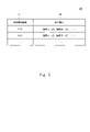
- FIG. 5 is a diagram illustrating the material specification information 10 in a table format.
- the table 100 of FIG. 5 has columns of material identification information 102 and material specifications 104 .
- Material identification information 102 indicates identification information assigned to material 60 .
- a material specification 104 indicates the specification of the material 60 .
- the material specification information 10 is represented by one record in the table 100. That is, the material specification information 10 associates the identification information of the material 60 with the material specification of the material 60 having the identification information.
- FIG. 6 is a diagram exemplifying the physical property information 20 in a table format.
- the table 200 in FIG. 6 has columns of product identification information 202 and physical properties 204 .
- the product identification information 202 indicates identification information of the product 70 .
- a physical property 204 indicates a physical property of the deliverable 70 .
- the physical properties of the product 70 are represented by showing a correspondence of "label representing type of physical property: physical amount of the physical property" for each physical property.
- the physical property information 20 is represented by one record in the table 200. That is, the physical property information 20 associates the identification information of the product 70 with the physical properties of the product 70 having the identification information.
- the acquisition unit 2020 acquires multiple pairs of material specification information 10 and physical property information 20 .
- a pair of material specification information 10 and physical property information 20 is stored in advance in any storage device accessible from the map image generation device 2000 .
- the acquisition unit 2020 acquires a pair of material specification information 10 and physical property information 20 by accessing this storage device.
- the acquisition unit 2020 may acquire a pair of the material specification information 10 and the physical property information 20 by accepting user input for inputting the pair of the material specification information 10 and the physical property information 20 .
- the acquisition unit 2020 may acquire a pair of material specification information 10 and physical property information 20 by receiving a pair of material specification information 10 and physical property information 20 transmitted from another device. good.
- the pair of material specification information 10 and physical property information 20 is generated by simulating the generation of the product 70 . Specifically, by giving specific material specifications as input and executing a simulation, the physical property information 20 indicating the predicted value of the physical quantity of each physical property is generated for the product 70 . Then, a pair of the generated physical property information 20 and the material specification information 10 indicating the material specification given as an input is obtained.
- a technology that realizes a simulation that acquires material specifications as input and outputs predictive data on the physical properties of deliverables that are produced in specific processes using the materials specified by the material specifications. can use existing technology.
- the pair of material specification information 10 and physical property information 20 may be generated by actually generating the deliverable 70.
- the product 70 is experimentally generated by using the material 60 represented by specific material specifications in the target process.
- the physical property information 20 is generated by measuring the physical quantity of each physical property of the generated product 70 . As a result, a pair of generated physical property information 20 and material specification information 10 representing the material 60 used is obtained.
- the physical property information 20 acquired by the acquisition unit 2020 may include information with different data representation methods. For example, different labels may be used for essentially identical physical properties. In addition, it is conceivable that the physical quantity of the same physical property is expressed in units different from each other. In such a case, the acquisition unit 2020 preferably unifies the data expression method by unifying labels, converting units, and the like. Such a situation in which the physical property information 20 has different data representation methods is, for example, the physical property information 20 generated using a simulation and the physical property information 20 generated by actually generating the product 70. It is considered possible when both are acquired. In addition, it is preferable that such unification of data expression methods is also performed for the material specification information 10 in the same manner.
- the self-organizing map generator 2040 uses the physical property information 20 to generate the self-organizing map 30 (S104).
- Each node of the self-organizing map 30 is assigned an n-dimensional physical property vector.
- the assignment of physical property vectors to each node is performed by learning the self-organizing map 30.
- Learning of the self-organizing map 30 can be performed by inputting n-dimensional training data used for learning into the self-organizing map 30 .
- An existing method can be used as a specific method for learning a self-organizing map using training data.
- the self-organizing map generator 2040 initializes the self-organizing map 30 by any method.
- an initialization method for example, a method of initializing the physical property vector of each node to a random value can be adopted.
- the self-organizing map generation unit 2040 generates a plurality of n-dimensional physical property vectors by extracting physical property amounts of n types of physical properties from each of the acquired plurality of physical property information 20 .
- the self-organizing map generation unit 2040 generates the self-organizing map 30 by learning the self-organizing map 30 using each of these physical property vectors as training data. As a result, the physical property vector of each node of the self-organizing map 30 becomes n-dimensional data indicating the value of each physical property quantity of n types of physical properties.
- the n-dimensional data obtained from the physical property information 20 may indicate the physical property amount of each of the n types of physical properties indicated by the physical property information 20 as they are, or each physical property amount may be obtained by a predetermined method (for example, normalization, standardization, etc.). A value obtained by conversion may be indicated.
- the number of physical properties indicated by the physical property information 20 may be greater than n.
- part of the data indicated by the physical property information 20 is used for generating the self-organizing map 30.
- FIG. which type of physical properties among the physical properties indicated by the physical property information 20 is used to generate the self-organizing map 30 may be determined in advance or may be designated by the user.
- the map image generator 2060 uses the material specification information 10 to allocate a specification vector to each node of the self-organizing map 30 in order to create the map image 40 from the self-organizing map 30 (S106).
- the specification vector obtained from the material specification information 10 may indicate values for all parameters indicated by the material specification information 10, or may indicate values for some of the parameters. good too. That is, if the number of dimensions of the specification vector is k, the value of k may be the same as the number of parameters indicated by the material specification information 10, or may be smaller than the number of parameters indicated by the material specification information 10.
- the material specification information 10 indicates both parameters that take continuous values (for example, the compounding ratio of substances) and parameters that do not take continuous values (for example, the type of processing).
- the specification vector is generated by parameters that take continuous values.
- the specification vector may indicate the value of the parameter indicated by the material specification information 10 as it is, or the value of each parameter may be converted by a predetermined method (for example, normalization or standardization). You may indicate the value obtained by
- the map image generation unit 2060 assigns each piece of material specification information 10 to the node in order to determine the assignment of the specification vector to each node.
- Physical property information 20 corresponding to the material specification information 10 is used to assign the material specification information 10 to the nodes. That is, the map image generator 2060 identifies a node having a physical property vector most similar to the physical property vector obtained from the physical property information 20 corresponding to the material specification information 10 .
- the map image generator 2060 assigns the material specification information 10 to the specified node.
- the map image generator 2060 assigns a specification vector obtained from the material specification information 10 to the node to which the material specification information 10 is assigned.
- the map image generation unit 2060 obtains, by estimation, specification vectors to be assigned to nodes to which the material specification information 10 is not assigned. That is, the map image generator 2060 estimates the distribution of the specification vectors based on the specification vectors of the nodes to which the material specification information 10 is assigned and the arrangement of those nodes on the map space. Then, the map image generation unit 2060 uses the estimated distribution to assign specification vectors to nodes to which the material specification information 10 has not been assigned.
- the map image generation unit 2060 estimates the distribution of the specification vectors by arbitrary interpolation processing such as linear interpolation or spline interpolation.
- the map image generation unit 2060 may estimate the distribution of the specification vectors by sparse estimation. Note that when estimating the distribution of the specification vectors, the estimation accuracy may be improved by further applying Bayesian estimation.
- the material specification information 10 is assigned You can increase the number of nodes that can be As a result, it is possible to increase the number of data points obtained by actual measurement in the distribution of material specifications, so that the distribution of specification vectors can be estimated with higher accuracy.
- the physical properties of the product 70 produced from the material 60 having certain material specifications it is possible to obtain both the predicted value and the likelihood (prediction error) by prediction using Bayesian estimation.
- the next data point to be actually measured (that is, the material specification to be targeted for simulation or the like) can be specified. According to this method, it is possible to search for materials from which the product 70 having better physical properties can be obtained with a smaller number of trials.
- FIG. 7 is a diagram exemplifying the configuration of the self-organizing map 30 in which a specification vector is assigned to each node in a table format.
- Table 300 of FIG. 7 has four columns: position 302 , physical property vector 304 , material identification information 306 , and specification vector 308 .
- Table 300 has one record per node.
- the material identification information 306 indicates, for a node to which the material specification information 10 is assigned, the identification information of the material 60 indicated by the material specification information 10 assigned to the node. In the record of the node to which the material specification information 10 is not assigned, the material identification information 306 indicates "-".
- the map image generator 2060 uses the specification vectors assigned to the nodes to generate the map image 40 (S108).
- a map image 40 is an image representing the arrangement of each node in the map space of the self-organizing map 30 .
- the nodes are subjected to either one or both of clustering and coloring based on the specification vector. Clustering and coloring based on the specification vector will be described below.
- the map image generator 2060 clusters the nodes based on the specification vectors assigned to each node.
- an existing technique can be used as a technique for clustering nodes based on vectors associated with each of the plurality of nodes.
- the map image generator 2060 clusters nodes using a clustering algorithm such as the k-means method.
- the number of clusters to be generated may be fixed, specified by the user, or calculated as a result of executing a clustering algorithm.
- the map image generation unit 2060 includes in the map image 40 a display that allows identification of each of the plurality of clusters generated by the clustering.
- the map image 40 shows the boundary lines of each cluster.
- FIG. 8 is a diagram illustrating a map image 40 in which nodes are clustered.
- each square in the two-dimensional squares represents a node.
- the map image 40 in FIG. 8 has seven clusters. Clusters are separated by borders that are thicker than node borders.
- the display that makes clusters identifiable is not limited to borders.
- the map image generation unit 2060 may assign a unique color or pattern to each of a plurality of clusters, and assign each node included in each cluster the color or pattern assigned to that cluster.
- the map image generation unit 2060 colors each node based on the specification vector of the node.
- the map image generation unit 2060 may convert the magnitude of the components of one or more reference colors (for example, three primary colors) constituting the color assigned to the node to any element of the specification vector (that is, the specification parameter). determined based on the value of A color assigned to a node is hereinafter referred to as an assigned color.
- a specific example of a method of assigning colors to nodes will be given below.
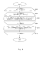
- FIG. 9 is a flowchart illustrating the flow of processing for assigning colors to nodes.
- S202 to S212 constitute loop processing L1.
- Loop processing L1 is executed once for each node included in self-organizing map 30 .
- the map image generation unit 2060 determines whether the loop process L1 has been executed for all nodes. If the loop process L1 has already been executed for all nodes, the process of FIG. 9 ends. On the other hand, if there are nodes that have not yet been subjected to the loop processing L1, the map image generator 2060 selects one node from among them. The node selected here is denoted as node i.
- S204 to S208 constitute loop processing L2.
- the loop process L2 is executed once for each type of specification parameter used for determining assigned colors.
- the map image generation unit 2060 determines whether or not the loop process L2 has been executed for all types of specification parameters used for determining assigned colors. If the loop process L2 has already been executed for all types of specification parameters used for determining assigned colors, the process of FIG. 9 proceeds to S210. On the other hand, if there are specification parameters that have not yet been subjected to loop processing L2 among the specification parameters used to determine the assigned colors, the map image generation unit 2060 selects one specification parameter from among the specification parameters. select. The specification parameter selected here is referred to as the j-th specification parameter.
- the map image generator 2060 determines the magnitude of the j-th reference color component in the assigned color of the node i based on the value of the j-th parameter of the node i's specification vector. For example, the magnitude of the j-th reference color component in the assigned color of node i is based on the numerical range of values indicated by the specification vector for the j-th parameter and the numerical range of the magnitude of each reference color component. It is calculated by a conversion formula determined by This conversion formula is represented, for example, by the following formula (1).
- c[i,j] represents the magnitude of the j-th reference color component in the assigned color of node i.
- x[i,j] is the value indicated by the dimension vector of node i for the j-th dimension parameter.
- f() represents a conversion formula.
- W[j] represents the size of the numerical range of values indicated by the specification vector for the j-th specification parameter.
- C represents the magnitude of the numerical range of each reference color component.
- the larger the value indicated by the specification vector for the j-th specification parameter the larger the j-th reference color component.
- the magnitude of the jth reference color component monotonically increases with respect to the value that the dimension vector indicates for the jth dimension parameter.
- the magnitude of the j-th reference color component does not necessarily have to monotonically increase with respect to the value indicated by the specification vector for the j-th specification parameter.
- the smaller the value indicated by the specification vector for the jth specification parameter the larger the value set for the jth reference color component.
- S208 is the end of loop processing L2. Therefore, the processing in FIG. 9 proceeds to S204.
- S212 is the end of loop processing L1. Therefore, the processing in FIG. 9 proceeds to S202.
- the map image generation unit 2060 generates the map image 40 based on the color allocation to the nodes thus determined. Specifically, the map image generation unit 2060 generates the map image 40 by expressing each node arranged on the map space with the assigned color of the node.
- the map image 40 is an image including squares in which each square is represented (for example, filled) with the assigned color of the node corresponding to the square.
- FIG. 10 is a diagram illustrating a map image 40 colored based on the specification vector.
- the color of the square corresponding to each node is set to the assigned color of that node.
- the difference in color is represented by the difference in the density of diagonal lines.
- node placement is not limited to the method of using squares.
- node placement may be expressed using a grid.
- a predetermined range around each grid point (for example, a circle with a predetermined radius centered on the grid point) is represented by the assigned color of the node corresponding to the grid point.
- An image of a grid is obtained.
- the map image generation device 2000 may acquire target information, which is information representing desired physical properties of the product 70 , and include in the map image 40 an indication representing nodes corresponding to the desired physical properties. This display is hereinafter referred to as target display. If a node corresponding to a desired physical property can be represented on the map image 40, the user of the map image generation device 2000 can easily search for the material 60 capable of producing the product 70 having the desired physical property. A specific description will be given below.
- the map image generation device 2000 acquires target information.
- the target information is input by the user of the map image generation device 2000.
- the acquisition of the target information may be performed before the map image 40 is generated, or may be performed after the map image 40 is generated. In the latter case, for example, the map image generation device 2000 acquires the target information after outputting the map image 40 that does not include the target display, and updates the map image 40 so that the target display is included.
- the map image generation device 2000 generates a physical property vector from target information.
- a method of generating a physical property vector from target information is the same as the method of generating a physical property vector from the physical property information 20 .
- the map image generation device 2000 identifies, from among the nodes of the self-organizing map 30, the node having the physical property vector with the highest degree of similarity to the physical property vector obtained from the target information.
- the map image generation device 2000 then includes in the map image 40 a target indication indicating that this node is a node corresponding to the desired physical property.
- FIG. 11 is a diagram illustrating a map image 40 including target indications.
- the target display is represented by numeral 42 .
- the node with the target indication 42 represents the physical property closest to the desired physical property in the physical property distribution represented by the self-organizing map 30 . Therefore, the specification vector assigned to this node is the material specification vector with the highest probability of generating the product 70 having the desired physical properties in the distribution of the material specifications represented by the self-organizing map 30 . It can be said that it represents the origin. Therefore, by viewing the map image 40 including the target display 42, the user of the map image generation device 2000 can obtain a product having a desired physical property from the specification vector of the node to which the target display 42 is attached. It is possible to grasp material specifications with a high probability that 70 can be generated.
- the user searches for a material 60 capable of producing a product 70 having desired physical properties, starting from the material specifications represented by the specification vectors of the nodes to which the target indications 42 are attached. That is, the user uses the material specifications represented by the specification vectors of the nodes attached with the target display 42 and the material specifications of one or more patterns close to the material specifications to execute the simulation or , performs the actual generation of the deliverable 70 . Then, based on the results of the simulation and the generation of the product 70, the user specifies the material specifications with which the product 70 having desired physical properties can be produced. According to this method, by using the map image 40, it is possible to easily specify the material specifications to be used as the starting point of the search. can do.
- the range of material search (material specifications close to the material specifications represented by the specification vectors of the nodes to which the target display 42 is attached) and the order of material search are specified based on the clusters and colors of the nodes. It is preferable to For example, the user searches for materials in the cluster containing the node marked with the target indicator 42 . In the example of FIG. 11, the node with the target display 42 is included in the upper rightmost cluster. The user then searches for materials in this cluster. In addition, for example, the user searches for materials in order from the node having a color that is highly similar to the color of the node to which the target indication 42 is attached.
- the target display 42 may not only be a mark for specifying a node, but may also include other information.
- target representation 42 may include material specifications represented by corresponding nodes.
- FIG. 12 is a diagram illustrating a case where material specifications are indicated on the target display 42. As shown in FIG. In FIG. 12, a target display 42 represents the compounding ratio of physical properties A, B, and C. In FIG.
- the values indicated by the specification vectors may be values obtained by converting the parameter values of the material specifications by means of normalization or the like. In such a case, it is preferable that the values included in the target display 42 are not the values indicated by the specification vectors themselves, but the values converted into parameter values of the material specifications.
- the map image generation device 2000 outputs the generated map image 40 .
- the output mode of the map image 40 is arbitrary.
- the map image generation device 2000 stores the map image 40 in any storage device accessible from the map image generation device 2000 .
- the map image generation device 2000 displays the map image 40 on any display device that can be controlled from the map image generation device 2000 .
- the map image generation device 2000 transmits the map image 40 to any device communicably connected to the map image generation device 2000 .
- the screen When the map image 40 is displayed on a display device, the screen preferably has the function of further displaying information about each node.
- the information about the node is, for example, a physical property vector or specification vector assigned to the node.
- a physical property vector or specification vector assigned to the node For example, in response to a user selecting (eg, mouseover) a particular node, information about that node may be displayed. If the values of physical property vectors and specification vectors assigned to nodes have been transformed by normalization, etc., they can be returned to the parameter values of physical properties and material specifications by inversely transforming them. It is preferable to display it on the screen after that.
- Non-transitory computer readable media include various types of tangible storage media.
- Examples of non-transitory computer-readable media include magnetic recording media (e.g., floppy disks, magnetic tapes, hard disk drives), magneto-optical recording media (e.g., magneto-optical discs), CD-ROMs, CD-Rs, CD-Rs /W, including semiconductor memory (e.g. mask ROM, PROM (programmable ROM), EPROM (erasable PROM), flash ROM, RAM).
- the program may also be provided to the computer on various types of transitory computer readable medium. Examples of transitory computer-readable media include electrical signals, optical signals, and electromagnetic waves. Transitory computer-readable media can deliver the program to the computer via wired channels, such as wires and optical fibers, or wireless channels.
- map image generating means for generating a map image representing each of the nodes arranged on the map space;
- the map image generating means is Using each of the material specification information, assign a specification vector indicating a value related to the material specification to each of the nodes;
- a map image generation device that performs one or both of clustering and coloring of each of the nodes in the map image based on the assignment of the specification vectors to the nodes.
- the map image generating means is for each of the plurality of material specification information, identifying the node to which the physical property vector most similar to the physical property vector obtained from the physical property information corresponding to the material specification information is assigned; By performing interpolation processing based on the arrangement of each of the identified nodes in the map space and the specification vector assigned to each of the identified nodes, assigning to the nodes other than each of the identified nodes 1.
- the map image generation device according to appendix 1, wherein the specification vector is calculated.
- the map image generating means is clustering each of the nodes based on the assignment of the feature vector to each of the nodes; 3.
- the map image generation device according to appendix 1 or 2, wherein the map image includes a display that allows each cluster to be identified from each other.
- the color of each node is determined by the size of one or more reference color components that constitute the color
- the map image generating means determines the size of each reference color component in the color assigned to the node using the value indicated by the specification vector assigned to the node for the parameter corresponding to the reference color. 3.
- the map image generation device according to any one of appendices 1 to 3.
- the map image generating means is obtaining target information representing desired physical properties of the deliverable; 5.
- map image generation according to any one of Appendices 1 to 4, wherein the map image includes a target display capable of identifying the node to which the physical property vector most similar to the physical property vector obtained from the target information is assigned.
- Device. (Appendix 6) 6.
- a control method implemented by a computer comprising: For each of a plurality of patterns of materials that can be used in the target process, material specification information that represents the material specifications of the material, and physical property amounts for each of the multiple physical properties of the deliverable that can be generated in the process using the material an acquisition step of acquiring physical property information indicating Using the physical property information, a self-organizing map is generated in which each node is assigned a position on the map space and a physical property vector indicating a physical property amount of each of a plurality of types of physical properties of the product.
- a transformation map generation step a map image generating step of generating a map image representing each of the nodes arranged on the map space;
- a map image generating step Using each of the material specification information, assign a specification vector indicating a value related to the material specification to each of the nodes;
- a control method that clusters and/or colors each of the nodes in the map image based on the assignment of the feature vectors to the nodes.
- the color of each node is determined by the size of one or more reference color components that constitute the color
- the size of each reference color component in the color assigned to the node is determined using the value indicated by the specification vector assigned to the node for the parameter corresponding to the reference color. 10.
- the control method according to any one of appendices 7 to 9. (Appendix 11) In the map image generation step, obtaining target information representing desired physical properties of the deliverable; 11.
- a transformation map generation step a map image generating step of generating a map image representing each of the nodes arranged on the map space;
- a map image generation step Using each of the material specification information, assign a specification vector indicating a value related to the material specification to each of the nodes;
- a non-transitory computer-readable medium that clusters and/or colors each of the nodes in the map image based on the assignment of the feature vectors to the nodes.
- the color of each node is determined by the size of one or more reference color components that constitute the color
- the size of each reference color component in the color assigned to the node is determined using the value indicated by the specification vector assigned to the node for the parameter corresponding to the reference color. 16.
- Appendix 17 In the map image generating step, obtaining target information representing desired physical properties of the deliverable; 17.
- computer readable medium (Appendix 18) 18.
- Material specification information 20 Physical property information 30 Self-organizing map 40 Map image 42 Target display 60 Material 70 Product 100 Table 102 Material identification information 104 Material specification 200 Table 202 Product identification information 204 Physical property 300 Table 302 Position 304 Physical property vector 306 material identification information 308 specification vector 500 computer 502 bus 504 processor 506 memory 508 storage device 510 input/output interface 512 network interface 2000 map image generator 2020 acquisition unit 2040 self-organizing map generator 2060 map image generator
Landscapes
- Engineering & Computer Science (AREA)
- Theoretical Computer Science (AREA)
- Physics & Mathematics (AREA)
- General Physics & Mathematics (AREA)
- Computer Vision & Pattern Recognition (AREA)
- Evolutionary Computation (AREA)
- Artificial Intelligence (AREA)
- Software Systems (AREA)
- Medical Informatics (AREA)
- Databases & Information Systems (AREA)
- Computing Systems (AREA)
- General Health & Medical Sciences (AREA)
- Health & Medical Sciences (AREA)
- Multimedia (AREA)
- Data Mining & Analysis (AREA)
- General Engineering & Computer Science (AREA)
- Bioinformatics & Cheminformatics (AREA)
- Bioinformatics & Computational Biology (AREA)
- Evolutionary Biology (AREA)
- Life Sciences & Earth Sciences (AREA)
- Computer Hardware Design (AREA)
- Geometry (AREA)
- Management, Administration, Business Operations System, And Electronic Commerce (AREA)
- Information Retrieval, Db Structures And Fs Structures Therefor (AREA)
Priority Applications (4)
| Application Number | Priority Date | Filing Date | Title |
|---|---|---|---|
| US18/280,097 US20240153158A1 (en) | 2021-03-18 | 2022-02-14 | Map image generation apparatus, control method, and non-transitory computer readable medium |
| JP2023506874A JP7598107B2 (ja) | 2021-03-18 | 2022-02-14 | マップ画像生成装置、制御方法、及びプログラム |
| CN202280022301.7A CN117043779A (zh) | 2021-03-18 | 2022-02-14 | 映射图像生成设备、控制方法和非暂时性计算机可读介质 |
| EP22770966.4A EP4310714A4 (en) | 2021-03-18 | 2022-02-14 | Map image generation device, control method, and non-transitory computer-readable medium |
Applications Claiming Priority (2)
| Application Number | Priority Date | Filing Date | Title |
|---|---|---|---|
| JP2021044486 | 2021-03-18 | ||
| JP2021-044486 | 2021-03-18 |
Publications (1)
| Publication Number | Publication Date |
|---|---|
| WO2022196207A1 true WO2022196207A1 (ja) | 2022-09-22 |
Family
ID=83322228
Family Applications (1)
| Application Number | Title | Priority Date | Filing Date |
|---|---|---|---|
| PCT/JP2022/005624 Ceased WO2022196207A1 (ja) | 2021-03-18 | 2022-02-14 | マップ画像生成装置、制御方法、及び非一時的なコンピュータ可読媒体 |
Country Status (5)
| Country | Link |
|---|---|
| US (1) | US20240153158A1 (https=) |
| EP (1) | EP4310714A4 (https=) |
| JP (1) | JP7598107B2 (https=) |
| CN (1) | CN117043779A (https=) |
| WO (1) | WO2022196207A1 (https=) |
Families Citing this family (1)
| Publication number | Priority date | Publication date | Assignee | Title |
|---|---|---|---|---|
| WO2025076337A1 (en) * | 2023-10-05 | 2025-04-10 | Schlumberger Technology Corporation | Automating the monitoring of a large population of field systems |
Citations (5)
| Publication number | Priority date | Publication date | Assignee | Title |
|---|---|---|---|---|
| WO2006121057A1 (ja) * | 2005-05-10 | 2006-11-16 | Kyoto University | 化合物群表示装置、化合物群表示方法、プログラム、及びコンピュータ読み取り可能な記録媒体 |
| JP2008293315A (ja) * | 2007-05-25 | 2008-12-04 | Yokohama Rubber Co Ltd:The | データ解析プログラム、データ解析装置、構造体の設計プログラム、および構造体の設計装置 |
| JP2014026459A (ja) * | 2012-07-26 | 2014-02-06 | Shizuoka Prefecture | 物質特性可視化法、物質特性可視化装置、物質特性可視化プログラム、および記録媒体 |
| JP2016148988A (ja) | 2015-02-12 | 2016-08-18 | 横浜ゴム株式会社 | データの分析方法およびデータの表示方法 |
| JP2021044486A (ja) | 2019-09-13 | 2021-03-18 | キオクシア株式会社 | 半導体装置およびその製造方法 |
Family Cites Families (1)
| Publication number | Priority date | Publication date | Assignee | Title |
|---|---|---|---|---|
| WO2006077981A1 (ja) * | 2005-01-21 | 2006-07-27 | Miyazaki Prefecture | 高スループット機能性評価方法、プログラム、及び装置 |
-
2022
- 2022-02-14 US US18/280,097 patent/US20240153158A1/en active Pending
- 2022-02-14 EP EP22770966.4A patent/EP4310714A4/en active Pending
- 2022-02-14 JP JP2023506874A patent/JP7598107B2/ja active Active
- 2022-02-14 WO PCT/JP2022/005624 patent/WO2022196207A1/ja not_active Ceased
- 2022-02-14 CN CN202280022301.7A patent/CN117043779A/zh active Pending
Patent Citations (5)
| Publication number | Priority date | Publication date | Assignee | Title |
|---|---|---|---|---|
| WO2006121057A1 (ja) * | 2005-05-10 | 2006-11-16 | Kyoto University | 化合物群表示装置、化合物群表示方法、プログラム、及びコンピュータ読み取り可能な記録媒体 |
| JP2008293315A (ja) * | 2007-05-25 | 2008-12-04 | Yokohama Rubber Co Ltd:The | データ解析プログラム、データ解析装置、構造体の設計プログラム、および構造体の設計装置 |
| JP2014026459A (ja) * | 2012-07-26 | 2014-02-06 | Shizuoka Prefecture | 物質特性可視化法、物質特性可視化装置、物質特性可視化プログラム、および記録媒体 |
| JP2016148988A (ja) | 2015-02-12 | 2016-08-18 | 横浜ゴム株式会社 | データの分析方法およびデータの表示方法 |
| JP2021044486A (ja) | 2019-09-13 | 2021-03-18 | キオクシア株式会社 | 半導体装置およびその製造方法 |
Non-Patent Citations (1)
| Title |
|---|
| See also references of EP4310714A4 |
Also Published As
| Publication number | Publication date |
|---|---|
| EP4310714A1 (en) | 2024-01-24 |
| CN117043779A (zh) | 2023-11-10 |
| JPWO2022196207A1 (https=) | 2022-09-22 |
| US20240153158A1 (en) | 2024-05-09 |
| JP7598107B2 (ja) | 2024-12-11 |
| EP4310714A4 (en) | 2025-03-19 |
Similar Documents
| Publication | Publication Date | Title |
|---|---|---|
| WO2022089218A1 (zh) | 机器学习模型的训练方法、训练装置、预测系统 | |
| JP6863926B2 (ja) | データ分析システム及びデータ分析方法 | |
| JP2010157214A (ja) | 遺伝子クラスタリングプログラム、遺伝子クラスタリング方法及び遺伝子クラスター解析装置 | |
| US20230153491A1 (en) | System for estimating feature value of material | |
| JP7598107B2 (ja) | マップ画像生成装置、制御方法、及びプログラム | |
| JP6773412B2 (ja) | コロプレスマップの設計 | |
| Hahn et al. | Hidden Second‐order Stationary Spatial Point Processes | |
| Le Cao et al. | Package ‘mixOmics’ | |
| JP7572664B2 (ja) | 特異材料検出装置、制御方法、及びプログラム | |
| JP7621598B2 (ja) | 推奨データ生成装置、制御方法、及びプログラム | |
| JP7164060B1 (ja) | 情報処理装置、情報処理方法及び情報処理プログラム | |
| WO2022196209A1 (ja) | 物性マップ画像生成装置、制御方法、及び非一時的なコンピュータ可読媒体 | |
| Torrente et al. | DepthTools: an R package for a robust analysis of gene expression data | |
| JP7701681B2 (ja) | マップ生成装置、マップ生成方法、及びプログラム | |
| Walker | Visualising multi-objective populations with treemaps | |
| EP4506848A1 (en) | Recommendation data generation device, recommendation data generation method, and non-transitory computer-readable medium | |
| KR20240028822A (ko) | 사용자 맞춤형 솔루션을 제공하기 위한 다중 센서 기반의 예측 모델 생성 방법 및 그러한 방법을 수행하는 전자 장치 | |
| JP6942104B2 (ja) | 判定装置、判定方法、および判定プログラム | |
| dos Santos Fernandes et al. | Generating diverse clustering datasets with targeted characteristics | |
| CN119150168B (zh) | 一种生理数据分类方法及电子设备 | |
| Zhang et al. | Image segmentation by selecting eigenvectors based on extended information entropy | |
| JP4302466B2 (ja) | 発現プロファイル解析システム、発現プロファイル解析方法、発現プロファイル解析プログラム、およびそのプログラムを記録した記録媒体 | |
| JPWO2002050767A1 (ja) | 多変量で記述された大量情報を高精度に分類する方法およびシステム | |
| Mao et al. | Zero-Shot Recognition by Using Attention Mechanism | |
| KR20260022807A (ko) | 대체 단백질 소재예측 장치 및 방법 |
Legal Events
| Date | Code | Title | Description |
|---|---|---|---|
| 121 | Ep: the epo has been informed by wipo that ep was designated in this application |
Ref document number: 22770966 Country of ref document: EP Kind code of ref document: A1 |
|
| WWE | Wipo information: entry into national phase |
Ref document number: 18280097 Country of ref document: US |
|
| WWE | Wipo information: entry into national phase |
Ref document number: 2023506874 Country of ref document: JP |
|
| WWE | Wipo information: entry into national phase |
Ref document number: 202280022301.7 Country of ref document: CN |
|
| WWE | Wipo information: entry into national phase |
Ref document number: 2022770966 Country of ref document: EP |
|
| NENP | Non-entry into the national phase |
Ref country code: DE |
|
| ENP | Entry into the national phase |
Ref document number: 2022770966 Country of ref document: EP Effective date: 20231018 |