WO2022196207A1 - Map image generation device, control method, and non-transitory computer-readable medium - Google Patents
Map image generation device, control method, and non-transitory computer-readable medium Download PDFInfo
- Publication number
- WO2022196207A1 WO2022196207A1 PCT/JP2022/005624 JP2022005624W WO2022196207A1 WO 2022196207 A1 WO2022196207 A1 WO 2022196207A1 JP 2022005624 W JP2022005624 W JP 2022005624W WO 2022196207 A1 WO2022196207 A1 WO 2022196207A1
- Authority
- WO
- WIPO (PCT)
- Prior art keywords
- map image
- physical property
- nodes
- map
- node
- Prior art date
Links
- 238000000034 method Methods 0.000 title claims description 82
- 239000000463 material Substances 0.000 claims abstract description 247
- 239000013598 vector Substances 0.000 claims abstract description 174
- 230000000704 physical effect Effects 0.000 claims description 238
- 230000008569 process Effects 0.000 claims description 34
- 238000012545 processing Methods 0.000 claims description 26
- 239000003086 colorant Substances 0.000 claims description 18
- 238000004040 coloring Methods 0.000 claims description 7
- 230000009466 transformation Effects 0.000 claims description 6
- 238000010586 diagram Methods 0.000 description 18
- 238000009826 distribution Methods 0.000 description 17
- 238000003860 storage Methods 0.000 description 13
- 238000004088 simulation Methods 0.000 description 8
- 238000012356 Product development Methods 0.000 description 6
- 238000006243 chemical reaction Methods 0.000 description 5
- 238000005516 engineering process Methods 0.000 description 5
- 238000010606 normalization Methods 0.000 description 4
- 239000000126 substance Substances 0.000 description 4
- 238000012549 training Methods 0.000 description 3
- 238000004458 analytical method Methods 0.000 description 2
- 239000004918 carbon fiber reinforced polymer Substances 0.000 description 2
- 238000013329 compounding Methods 0.000 description 2
- 238000013461 design Methods 0.000 description 2
- 239000000835 fiber Substances 0.000 description 2
- 230000006870 function Effects 0.000 description 2
- 238000002156 mixing Methods 0.000 description 2
- 229920000049 Carbon (fiber) Polymers 0.000 description 1
- 229920003043 Cellulose fiber Polymers 0.000 description 1
- 239000004593 Epoxy Substances 0.000 description 1
- 239000004721 Polyphenylene oxide Substances 0.000 description 1
- 230000009471 action Effects 0.000 description 1
- 230000005540 biological transmission Effects 0.000 description 1
- 239000004917 carbon fiber Substances 0.000 description 1
- 230000001364 causal effect Effects 0.000 description 1
- 230000006835 compression Effects 0.000 description 1
- 238000007906 compression Methods 0.000 description 1
- 230000000694 effects Effects 0.000 description 1
- 238000011423 initialization method Methods 0.000 description 1
- 238000004519 manufacturing process Methods 0.000 description 1
- 238000005259 measurement Methods 0.000 description 1
- 230000003287 optical effect Effects 0.000 description 1
- 239000013307 optical fiber Substances 0.000 description 1
- 238000005457 optimization Methods 0.000 description 1
- 229920002239 polyacrylonitrile Polymers 0.000 description 1
- 229920000570 polyether Polymers 0.000 description 1
- 238000006116 polymerization reaction Methods 0.000 description 1
- 229920005989 resin Polymers 0.000 description 1
- 239000011347 resin Substances 0.000 description 1
- 239000011342 resin composition Substances 0.000 description 1
- 230000004044 response Effects 0.000 description 1
- 239000004065 semiconductor Substances 0.000 description 1
- 239000007787 solid Substances 0.000 description 1
- 229910001220 stainless steel Inorganic materials 0.000 description 1
- 239000010935 stainless steel Substances 0.000 description 1
- KKEYFWRCBNTPAC-UHFFFAOYSA-L terephthalate(2-) Chemical compound [O-]C(=O)C1=CC=C(C([O-])=O)C=C1 KKEYFWRCBNTPAC-UHFFFAOYSA-L 0.000 description 1
- 230000001131 transforming effect Effects 0.000 description 1
- 230000001052 transient effect Effects 0.000 description 1
Images


Classifications
-
- G—PHYSICS
- G06—COMPUTING; CALCULATING OR COUNTING
- G06T—IMAGE DATA PROCESSING OR GENERATION, IN GENERAL
- G06T11/00—2D [Two Dimensional] image generation
- G06T11/001—Texturing; Colouring; Generation of texture or colour
-
- G—PHYSICS
- G06—COMPUTING; CALCULATING OR COUNTING
- G06F—ELECTRIC DIGITAL DATA PROCESSING
- G06F30/00—Computer-aided design [CAD]
- G06F30/20—Design optimisation, verification or simulation
- G06F30/27—Design optimisation, verification or simulation using machine learning, e.g. artificial intelligence, neural networks, support vector machines [SVM] or training a model
-
- G—PHYSICS
- G06—COMPUTING; CALCULATING OR COUNTING
- G06T—IMAGE DATA PROCESSING OR GENERATION, IN GENERAL
- G06T7/00—Image analysis
- G06T7/90—Determination of colour characteristics
-
- G—PHYSICS
- G06—COMPUTING; CALCULATING OR COUNTING
- G06V—IMAGE OR VIDEO RECOGNITION OR UNDERSTANDING
- G06V10/00—Arrangements for image or video recognition or understanding
- G06V10/70—Arrangements for image or video recognition or understanding using pattern recognition or machine learning
- G06V10/762—Arrangements for image or video recognition or understanding using pattern recognition or machine learning using clustering, e.g. of similar faces in social networks
-
- G—PHYSICS
- G06—COMPUTING; CALCULATING OR COUNTING
- G06F—ELECTRIC DIGITAL DATA PROCESSING
- G06F2111/00—Details relating to CAD techniques
- G06F2111/10—Numerical modelling
-
- G—PHYSICS
- G06—COMPUTING; CALCULATING OR COUNTING
- G06F—ELECTRIC DIGITAL DATA PROCESSING
- G06F2113/00—Details relating to the application field
- G06F2113/26—Composites
-
- G—PHYSICS
- G06—COMPUTING; CALCULATING OR COUNTING
- G06T—IMAGE DATA PROCESSING OR GENERATION, IN GENERAL
- G06T2207/00—Indexing scheme for image analysis or image enhancement
- G06T2207/10—Image acquisition modality
- G06T2207/10024—Color image
Definitions
- This disclosure relates to technology for providing information related to product development.
- Patent Literature 1 discloses a system that uses a self-organizing map to support understanding of causal relationships between design values and physical property values of tires.
- Patent Document 1 a self-organizing map is used to identify which of a plurality of tire design variables is an important factor. Therefore, it is not assumed that the self-organizing map will be used for any other purpose.
- the present disclosure is made in view of such problems, and an object of the present disclosure is to provide a new technology that provides useful information for product development.
- the map image generation device of the present disclosure includes, for each of a plurality of patterns of materials that can be used in a target process, material specification information that represents the material specifications of the material, and a product that can be generated in the process using the material.
- an acquisition unit that acquires physical property information indicating physical property amounts for each of a plurality of physical properties of the product;
- a self-organizing map generation unit that generates a self-organizing map in which each node is assigned a physical property vector, and a map image generation unit that generates a map image representing each of the nodes arranged on the map space.
- the map image generation unit uses each of the material specification information to allocate a specification vector indicating a value related to the material specification to each of the nodes, and based on the assignment of the specification vector to each of the nodes, the Cluster and/or color each node in the map image.
- the control method of the present disclosure is executed by a computer.
- the control method includes, for each of a plurality of patterns of materials that can be used in a target process, material specification information representing the material specifications of the material, and a plurality of physical properties of products that can be produced in the process using the material.
- each of the nodes is assigned a specification vector indicating a value related to the material specification, and based on the assignment of the specification vector to each of the nodes, the Cluster and/or color each node in the map image.
- the non-transitory computer-readable medium of the present disclosure stores a program that causes a computer to execute the control method of the present disclosure.
- FIG. 4 is a diagram illustrating an overview of the operation of the map image generation device of Embodiment 1;
- FIG. 2 is a block diagram illustrating the functional configuration of the map image generation device of Embodiment 1;
- FIG. It is a block diagram which illustrates the hardware constitutions of the computer which implement
- 4 is a flowchart illustrating the flow of processing executed by the map image generation device of Embodiment 1; It is a figure which illustrates material specification information in a table format. It is a figure which illustrates physical-property information in a table form.
- FIG. 3 is a diagram illustrating, in a table format, the configuration of a self-organizing map in which a specification vector is assigned to each node;
- FIG. 4 is a diagram illustrating a map image in which nodes are clustered;
- FIG. 10 is a flowchart illustrating a flow of processing for assigning colors to nodes;
- FIG. 4 is a diagram illustrating a map image colored based on specification vectors;
- FIG. 4 is a diagram illustrating a map image including target indications; It is a figure which illustrates the case where material specifications are shown on the target display.
- predetermined information such as predetermined values and threshold values is stored in advance in a storage device or the like that can be accessed from a device that uses the information.
- FIG. 1 is a diagram illustrating an overview of the operation of the map image generation device 2000 of the first embodiment.
- FIG. 1 is a diagram for facilitating understanding of the overview of the map image generation device 2000, and the operation of the map image generation device 2000 is not limited to that shown in FIG.
- the map image generation device 2000 generates a map image 40 for a deliverable 70 that can be generated in a specific process of product development (hereinafter, target process).
- the map image 40 is an image that expresses the correspondence relationship between the distribution of material specifications of the materials used to generate the product 70 and the distribution of physical properties of the product 70 .
- the deliverable 70 is what is predicted to be produced by processing the material 60 in the production process of the target process, or what is actually produced.
- Materials 60 are materials that are used to generate artifacts 70 .
- Various patterns of material 60 can be utilized in the process of interest.
- the physical properties of the product 70 may vary depending on the material 60 utilized.
- One pattern of the material 60 is specified by material specifications. In other words, materials 60 with different material specifications are treated as materials 60 with different patterns. On the other hand, materials 60 having the same material specifications are treated as materials 60 having the same pattern.
- Material specifications are represented, for example, by the type of material, the type of substances that make up the material, the mixing ratio of each substance, and the type of processing performed to create the material.
- Types of materials include, for example, carbon fiber reinforced plastics and stainless steel.
- the material specifications of the material 60 include the types of one or more carbon fibers that make up the material 60 (such as polyacrylonitrile fibers and carbonized cellulose fibers), and one or more resins that make up the material 60. type (epoxy, polyether terephthalate, etc.) and the blending ratio of those substances.
- the material specifications may further include the type of fiber directional polymerization method, the type of compression method, resin composition, and the like.
- the map image generation device 2000 performs the Material specification information 10 representing material specifications and physical property information 20 indicating physical properties of a product 70 that can be produced in a target process using the material 60 are acquired.
- the physical property information 20 indicates physical property quantities of each of a plurality of types of physical properties of the product 70 .
- Types of physical properties are, for example, flame retardancy, heat resistance, elastic modulus, toughness, and the like.
- the map image generation device 2000 uses the physical property information 20 to generate a self-organizing map 30 representing the physical property distribution of the product 70 .
- the self-organizing map 30 has a plurality of nodes arranged on an m-dimensional map space.
- m is set to 2 or 3 so that the map image 40 can be generated from the self-organizing map 30 .
- a node can be expressed as a square of squares, a grid on a grid, or the like.
- Each node of the self-organizing map 30 is assigned multi-dimensional data (hereinafter referred to as a physical property vector) representing the magnitude of each physical property of multiple types of physical properties.
- a physical property vector representing the magnitude of each physical property of multiple types of physical properties.
- the physical property vector is four-dimensional data representing the magnitude of each of these four types of physical properties.
- the number of dimensions of the physical property vector is assumed to be n. Note that n>m. That is, in the self-organizing map 30, the physical property vector space is a high-dimensional space, and the map space is a low-dimensional space.
- the physical property information 20 indicates physical property amounts for n or more types of physical properties.
- the map image generation device 2000 learns the self-organizing map 30 using the physical property quantities of the n types of physical properties indicated by the physical property information 20, thereby determining the physical property vector to be assigned to each node. , generates a self-organizing map 30 .
- the map image generation device 2000 assigns each piece of material specification information 10 to one of the nodes of the self-organizing map 30. Specifically, the map image generation device 2000 stores multidimensional data (hereinafter referred to as "specification vectors") representing respective values of a plurality of types of parameters (hereinafter referred to as "specification parameters") indicated by the material specification information 10 to nodes. assign.
- the specification vector obtained from the material specification information 10 is the physical property information 20 corresponding to the material specification information 10 (the product generated using the material 60 specified by the material specification information 10). It is assigned to the node having the physical property vector most similar to the n-dimensional data obtained from the physical property information 20) representing 70 physical properties.
- each pair of the material specification information 10 and the physical property information 20 acquired by the map image generation device 2000 is associated with one of the nodes of the self-organizing map 30 . That is, in the self-organizing map 30, the material specifications and the physical properties of the product 70 are associated.
- the map image generation device 2000 generates the map image 40 based on the correspondence between the nodes in the self-organizing map 30 and the specification vectors.
- a map image 40 represents the arrangement of each node in an m-dimensional space. Furthermore, each node of the map image 40 is either 1) clustered based on the correspondence between the node and the specification vector, or 2) each node of the map image 40 has a correspondence between the node and the specification vector. Colored based on attachment.
- a search for materials capable of producing such a product may be conducted.
- the methods of realizing such a search there is a method of simulating generation of a product while variously changing material specifications, or of generating a product experimentally.
- the correspondence relationship between the material specifications accumulated through such simulations and the experimental generation of deliverables and the physical properties of the deliverables (the correspondence relationship between the material specification information 10 and the physical property information 20 in the present disclosure)
- a method of performing inverse analysis to predict material specifications from desirable physical properties is also conceivable.
- the map image generation device 2000 generates a self-organizing map 30 using physical property vectors obtained from each of a plurality of physical property information 20, and expresses material specifications for each node of the self-organizing map 30. Assign a specification vector. Then, the map image generation device 2000 performs one or both of node clustering and coloring based on the assignment of material specifications to each node. As a result, the distribution of material specifications can be grasped on the self-organizing map representing the distribution of physical properties. That is, by using the map image 40, it is possible to grasp the correspondence relationship between the distribution of physical properties and the distribution of material specifications. Therefore, the map image 40 can be used for the reverse analysis described above.
- the product 70 having the desired physical properties can be obtained. It can be said that there is a high probability that
- the self-organizing map 30 generated based on the physical property vector is further subjected to clustering and coloring based on the specification vector. Therefore, it can be said that nodes classified into the same cluster or nodes assigned similar colors have similar physical properties and material specifications. Therefore, for example, the user of the map image generation device 2000 starts from a node that represents a physical property close to the desired physical property, and the surroundings of the material specifications represented by the node at the starting point (each node included in the same cluster as that node) or material specifications represented by each node with a color similar to that node). As a result, it is possible to efficiently search for materials capable of producing the product 70 having desired physical properties (with less time and less cost).
- the map image generation device 2000 of this embodiment will be described in more detail below.
- FIG. 2 is a block diagram illustrating the functional configuration of the map image generation device 2000 of Embodiment 1.
- the map image generation device 2000 has an acquisition section 2020 , a self-organizing map generation section 2040 and a map image generation section 2060 .
- the acquisition unit 2020 acquires the material specification information 10 and the physical property information 20 for each of the multiple patterns of the material 60 .
- the self-organizing map generator 2040 uses the physical property information 20 to generate the self-organizing map 30 .
- the map image generator 2060 assigns the specification vector obtained from each piece of material specification information 10 to each node of the self-organizing map 30 .
- the map image generator 2060 generates a map image 40 representing the arrangement of nodes in the map space of the self-organizing map 30.
- FIG. In the map image 40 nodes are clustered or colored based on the specification vectors assigned to the nodes.
- Each functional configuration unit of the map image generation device 2000 may be realized by hardware (eg, hardwired electronic circuit, etc.) that implements each functional configuration unit, or may be realized by a combination of hardware and software (eg, : a combination of an electronic circuit and a program that controls it, etc.).
- hardware e.g, hardwired electronic circuit, etc.
- software e.g, : a combination of an electronic circuit and a program that controls it, etc.
- FIG. 3 is a block diagram illustrating the hardware configuration of the computer 500 that implements the map image generation device 2000.
- Computer 500 is any computer.
- the computer 500 is a stationary computer such as a server machine or a PC (Personal Computer).
- the computer 500 is a portable computer such as a smart phone or a tablet terminal.
- Computer 500 may be a dedicated computer designed to implement map image generation device 2000, or a general-purpose computer.
- the computer 500 implements each function of the map image generation device 2000.
- the application is composed of a program for realizing each functional component of the map image generation device 2000 .
- the acquisition method of the above program is arbitrary.
- the program can be acquired from a storage medium (DVD disc, USB memory, etc.) in which the program is stored.
- the program can be obtained by downloading the program from a server device that manages the storage device in which the program is stored.
- Computer 500 has bus 502 , processor 504 , memory 506 , storage device 508 , input/output interface 510 and network interface 512 .
- the bus 502 is a data transmission path through which the processor 504, memory 506, storage device 508, input/output interface 510, and network interface 512 exchange data with each other.
- the method of connecting the processors 504 and the like to each other is not limited to bus connection.
- the processor 504 is various processors such as a CPU (Central Processing Unit), GPU (Graphics Processing Unit), or FPGA (Field-Programmable Gate Array).
- the memory 506 is a main memory implemented using a RAM (Random Access Memory) or the like.
- the storage device 508 is an auxiliary storage device implemented using a hard disk, SSD (Solid State Drive), memory card, ROM (Read Only Memory), or the like.
- the input/output interface 510 is an interface for connecting the computer 500 and input/output devices.
- the input/output interface 510 is connected to an input device such as a keyboard and an output device such as a display device.
- a network interface 512 is an interface for connecting the computer 500 to a network.
- This network may be a LAN (Local Area Network) or a WAN (Wide Area Network).
- the storage device 508 stores a program that implements each functional component of the map image generation device 2000 (a program that implements the application described above).
- the processor 504 implements each functional component of the map image generation device 2000 by reading this program into the memory 506 and executing it.
- the map image generation device 2000 may be realized by one computer 500 or may be realized by a plurality of computers 500. In the latter case, the configuration of each computer 500 need not be the same, and can be different.
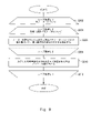
- FIG. 4 is a flowchart illustrating the flow of processing executed by the map image generation device 2000 of the first embodiment.
- the acquiring unit 2020 acquires the material specification information 10 and the physical property information 20 for each of the plurality of materials 60 that can be used in the target process (S102).
- the self-organizing map generator 2040 uses the physical property information 20 to generate the self-organizing map 30 (S104).
- the map image generator 2060 assigns the specification vector obtained from each item of material specification information 10 to any node of the self-organizing map 30 (S106).
- the map image generator 2060 generates the map image 40 from the self-organizing map 30 based on the assignment of the specification vectors to the nodes (S108).
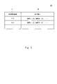
- FIG. 5 is a diagram illustrating the material specification information 10 in a table format.
- the table 100 of FIG. 5 has columns of material identification information 102 and material specifications 104 .
- Material identification information 102 indicates identification information assigned to material 60 .
- a material specification 104 indicates the specification of the material 60 .
- the material specification information 10 is represented by one record in the table 100. That is, the material specification information 10 associates the identification information of the material 60 with the material specification of the material 60 having the identification information.
- FIG. 6 is a diagram exemplifying the physical property information 20 in a table format.
- the table 200 in FIG. 6 has columns of product identification information 202 and physical properties 204 .
- the product identification information 202 indicates identification information of the product 70 .
- a physical property 204 indicates a physical property of the deliverable 70 .
- the physical properties of the product 70 are represented by showing a correspondence of "label representing type of physical property: physical amount of the physical property" for each physical property.
- the physical property information 20 is represented by one record in the table 200. That is, the physical property information 20 associates the identification information of the product 70 with the physical properties of the product 70 having the identification information.
- the acquisition unit 2020 acquires multiple pairs of material specification information 10 and physical property information 20 .
- a pair of material specification information 10 and physical property information 20 is stored in advance in any storage device accessible from the map image generation device 2000 .
- the acquisition unit 2020 acquires a pair of material specification information 10 and physical property information 20 by accessing this storage device.
- the acquisition unit 2020 may acquire a pair of the material specification information 10 and the physical property information 20 by accepting user input for inputting the pair of the material specification information 10 and the physical property information 20 .
- the acquisition unit 2020 may acquire a pair of material specification information 10 and physical property information 20 by receiving a pair of material specification information 10 and physical property information 20 transmitted from another device. good.
- the pair of material specification information 10 and physical property information 20 is generated by simulating the generation of the product 70 . Specifically, by giving specific material specifications as input and executing a simulation, the physical property information 20 indicating the predicted value of the physical quantity of each physical property is generated for the product 70 . Then, a pair of the generated physical property information 20 and the material specification information 10 indicating the material specification given as an input is obtained.
- a technology that realizes a simulation that acquires material specifications as input and outputs predictive data on the physical properties of deliverables that are produced in specific processes using the materials specified by the material specifications. can use existing technology.
- the pair of material specification information 10 and physical property information 20 may be generated by actually generating the deliverable 70.
- the product 70 is experimentally generated by using the material 60 represented by specific material specifications in the target process.
- the physical property information 20 is generated by measuring the physical quantity of each physical property of the generated product 70 . As a result, a pair of generated physical property information 20 and material specification information 10 representing the material 60 used is obtained.
- the physical property information 20 acquired by the acquisition unit 2020 may include information with different data representation methods. For example, different labels may be used for essentially identical physical properties. In addition, it is conceivable that the physical quantity of the same physical property is expressed in units different from each other. In such a case, the acquisition unit 2020 preferably unifies the data expression method by unifying labels, converting units, and the like. Such a situation in which the physical property information 20 has different data representation methods is, for example, the physical property information 20 generated using a simulation and the physical property information 20 generated by actually generating the product 70. It is considered possible when both are acquired. In addition, it is preferable that such unification of data expression methods is also performed for the material specification information 10 in the same manner.
- the self-organizing map generator 2040 uses the physical property information 20 to generate the self-organizing map 30 (S104).
- Each node of the self-organizing map 30 is assigned an n-dimensional physical property vector.
- the assignment of physical property vectors to each node is performed by learning the self-organizing map 30.
- Learning of the self-organizing map 30 can be performed by inputting n-dimensional training data used for learning into the self-organizing map 30 .
- An existing method can be used as a specific method for learning a self-organizing map using training data.
- the self-organizing map generator 2040 initializes the self-organizing map 30 by any method.
- an initialization method for example, a method of initializing the physical property vector of each node to a random value can be adopted.
- the self-organizing map generation unit 2040 generates a plurality of n-dimensional physical property vectors by extracting physical property amounts of n types of physical properties from each of the acquired plurality of physical property information 20 .
- the self-organizing map generation unit 2040 generates the self-organizing map 30 by learning the self-organizing map 30 using each of these physical property vectors as training data. As a result, the physical property vector of each node of the self-organizing map 30 becomes n-dimensional data indicating the value of each physical property quantity of n types of physical properties.
- the n-dimensional data obtained from the physical property information 20 may indicate the physical property amount of each of the n types of physical properties indicated by the physical property information 20 as they are, or each physical property amount may be obtained by a predetermined method (for example, normalization, standardization, etc.). A value obtained by conversion may be indicated.
- the number of physical properties indicated by the physical property information 20 may be greater than n.
- part of the data indicated by the physical property information 20 is used for generating the self-organizing map 30.
- FIG. which type of physical properties among the physical properties indicated by the physical property information 20 is used to generate the self-organizing map 30 may be determined in advance or may be designated by the user.
- the map image generator 2060 uses the material specification information 10 to allocate a specification vector to each node of the self-organizing map 30 in order to create the map image 40 from the self-organizing map 30 (S106).
- the specification vector obtained from the material specification information 10 may indicate values for all parameters indicated by the material specification information 10, or may indicate values for some of the parameters. good too. That is, if the number of dimensions of the specification vector is k, the value of k may be the same as the number of parameters indicated by the material specification information 10, or may be smaller than the number of parameters indicated by the material specification information 10.
- the material specification information 10 indicates both parameters that take continuous values (for example, the compounding ratio of substances) and parameters that do not take continuous values (for example, the type of processing).
- the specification vector is generated by parameters that take continuous values.
- the specification vector may indicate the value of the parameter indicated by the material specification information 10 as it is, or the value of each parameter may be converted by a predetermined method (for example, normalization or standardization). You may indicate the value obtained by
- the map image generation unit 2060 assigns each piece of material specification information 10 to the node in order to determine the assignment of the specification vector to each node.
- Physical property information 20 corresponding to the material specification information 10 is used to assign the material specification information 10 to the nodes. That is, the map image generator 2060 identifies a node having a physical property vector most similar to the physical property vector obtained from the physical property information 20 corresponding to the material specification information 10 .
- the map image generator 2060 assigns the material specification information 10 to the specified node.
- the map image generator 2060 assigns a specification vector obtained from the material specification information 10 to the node to which the material specification information 10 is assigned.
- the map image generation unit 2060 obtains, by estimation, specification vectors to be assigned to nodes to which the material specification information 10 is not assigned. That is, the map image generator 2060 estimates the distribution of the specification vectors based on the specification vectors of the nodes to which the material specification information 10 is assigned and the arrangement of those nodes on the map space. Then, the map image generation unit 2060 uses the estimated distribution to assign specification vectors to nodes to which the material specification information 10 has not been assigned.
- the map image generation unit 2060 estimates the distribution of the specification vectors by arbitrary interpolation processing such as linear interpolation or spline interpolation.
- the map image generation unit 2060 may estimate the distribution of the specification vectors by sparse estimation. Note that when estimating the distribution of the specification vectors, the estimation accuracy may be improved by further applying Bayesian estimation.
- the material specification information 10 is assigned You can increase the number of nodes that can be As a result, it is possible to increase the number of data points obtained by actual measurement in the distribution of material specifications, so that the distribution of specification vectors can be estimated with higher accuracy.
- the physical properties of the product 70 produced from the material 60 having certain material specifications it is possible to obtain both the predicted value and the likelihood (prediction error) by prediction using Bayesian estimation.
- the next data point to be actually measured (that is, the material specification to be targeted for simulation or the like) can be specified. According to this method, it is possible to search for materials from which the product 70 having better physical properties can be obtained with a smaller number of trials.
- FIG. 7 is a diagram exemplifying the configuration of the self-organizing map 30 in which a specification vector is assigned to each node in a table format.
- Table 300 of FIG. 7 has four columns: position 302 , physical property vector 304 , material identification information 306 , and specification vector 308 .
- Table 300 has one record per node.
- the material identification information 306 indicates, for a node to which the material specification information 10 is assigned, the identification information of the material 60 indicated by the material specification information 10 assigned to the node. In the record of the node to which the material specification information 10 is not assigned, the material identification information 306 indicates "-".
- the map image generator 2060 uses the specification vectors assigned to the nodes to generate the map image 40 (S108).
- a map image 40 is an image representing the arrangement of each node in the map space of the self-organizing map 30 .
- the nodes are subjected to either one or both of clustering and coloring based on the specification vector. Clustering and coloring based on the specification vector will be described below.
- the map image generator 2060 clusters the nodes based on the specification vectors assigned to each node.
- an existing technique can be used as a technique for clustering nodes based on vectors associated with each of the plurality of nodes.
- the map image generator 2060 clusters nodes using a clustering algorithm such as the k-means method.
- the number of clusters to be generated may be fixed, specified by the user, or calculated as a result of executing a clustering algorithm.
- the map image generation unit 2060 includes in the map image 40 a display that allows identification of each of the plurality of clusters generated by the clustering.
- the map image 40 shows the boundary lines of each cluster.
- FIG. 8 is a diagram illustrating a map image 40 in which nodes are clustered.
- each square in the two-dimensional squares represents a node.
- the map image 40 in FIG. 8 has seven clusters. Clusters are separated by borders that are thicker than node borders.
- the display that makes clusters identifiable is not limited to borders.
- the map image generation unit 2060 may assign a unique color or pattern to each of a plurality of clusters, and assign each node included in each cluster the color or pattern assigned to that cluster.
- the map image generation unit 2060 colors each node based on the specification vector of the node.
- the map image generation unit 2060 may convert the magnitude of the components of one or more reference colors (for example, three primary colors) constituting the color assigned to the node to any element of the specification vector (that is, the specification parameter). determined based on the value of A color assigned to a node is hereinafter referred to as an assigned color.
- a specific example of a method of assigning colors to nodes will be given below.
- FIG. 9 is a flowchart illustrating the flow of processing for assigning colors to nodes.
- S202 to S212 constitute loop processing L1.
- Loop processing L1 is executed once for each node included in self-organizing map 30 .
- the map image generation unit 2060 determines whether the loop process L1 has been executed for all nodes. If the loop process L1 has already been executed for all nodes, the process of FIG. 9 ends. On the other hand, if there are nodes that have not yet been subjected to the loop processing L1, the map image generator 2060 selects one node from among them. The node selected here is denoted as node i.
- S204 to S208 constitute loop processing L2.
- the loop process L2 is executed once for each type of specification parameter used for determining assigned colors.
- the map image generation unit 2060 determines whether or not the loop process L2 has been executed for all types of specification parameters used for determining assigned colors. If the loop process L2 has already been executed for all types of specification parameters used for determining assigned colors, the process of FIG. 9 proceeds to S210. On the other hand, if there are specification parameters that have not yet been subjected to loop processing L2 among the specification parameters used to determine the assigned colors, the map image generation unit 2060 selects one specification parameter from among the specification parameters. select. The specification parameter selected here is referred to as the j-th specification parameter.
- the map image generator 2060 determines the magnitude of the j-th reference color component in the assigned color of the node i based on the value of the j-th parameter of the node i's specification vector. For example, the magnitude of the j-th reference color component in the assigned color of node i is based on the numerical range of values indicated by the specification vector for the j-th parameter and the numerical range of the magnitude of each reference color component. It is calculated by a conversion formula determined by This conversion formula is represented, for example, by the following formula (1).
- c[i,j] represents the magnitude of the j-th reference color component in the assigned color of node i.
- x[i,j] is the value indicated by the dimension vector of node i for the j-th dimension parameter.
- f() represents a conversion formula.
- W[j] represents the size of the numerical range of values indicated by the specification vector for the j-th specification parameter.
- C represents the magnitude of the numerical range of each reference color component.
- the larger the value indicated by the specification vector for the j-th specification parameter the larger the j-th reference color component.
- the magnitude of the jth reference color component monotonically increases with respect to the value that the dimension vector indicates for the jth dimension parameter.
- the magnitude of the j-th reference color component does not necessarily have to monotonically increase with respect to the value indicated by the specification vector for the j-th specification parameter.
- the smaller the value indicated by the specification vector for the jth specification parameter the larger the value set for the jth reference color component.
- S208 is the end of loop processing L2. Therefore, the processing in FIG. 9 proceeds to S204.
- S212 is the end of loop processing L1. Therefore, the processing in FIG. 9 proceeds to S202.
- the map image generation unit 2060 generates the map image 40 based on the color allocation to the nodes thus determined. Specifically, the map image generation unit 2060 generates the map image 40 by expressing each node arranged on the map space with the assigned color of the node.
- the map image 40 is an image including squares in which each square is represented (for example, filled) with the assigned color of the node corresponding to the square.
- FIG. 10 is a diagram illustrating a map image 40 colored based on the specification vector.
- the color of the square corresponding to each node is set to the assigned color of that node.
- the difference in color is represented by the difference in the density of diagonal lines.
- node placement is not limited to the method of using squares.
- node placement may be expressed using a grid.
- a predetermined range around each grid point (for example, a circle with a predetermined radius centered on the grid point) is represented by the assigned color of the node corresponding to the grid point.
- An image of a grid is obtained.
- the map image generation device 2000 may acquire target information, which is information representing desired physical properties of the product 70 , and include in the map image 40 an indication representing nodes corresponding to the desired physical properties. This display is hereinafter referred to as target display. If a node corresponding to a desired physical property can be represented on the map image 40, the user of the map image generation device 2000 can easily search for the material 60 capable of producing the product 70 having the desired physical property. A specific description will be given below.
- the map image generation device 2000 acquires target information.
- the target information is input by the user of the map image generation device 2000.
- the acquisition of the target information may be performed before the map image 40 is generated, or may be performed after the map image 40 is generated. In the latter case, for example, the map image generation device 2000 acquires the target information after outputting the map image 40 that does not include the target display, and updates the map image 40 so that the target display is included.
- the map image generation device 2000 generates a physical property vector from target information.
- a method of generating a physical property vector from target information is the same as the method of generating a physical property vector from the physical property information 20 .
- the map image generation device 2000 identifies, from among the nodes of the self-organizing map 30, the node having the physical property vector with the highest degree of similarity to the physical property vector obtained from the target information.
- the map image generation device 2000 then includes in the map image 40 a target indication indicating that this node is a node corresponding to the desired physical property.
- FIG. 11 is a diagram illustrating a map image 40 including target indications.
- the target display is represented by numeral 42 .
- the node with the target indication 42 represents the physical property closest to the desired physical property in the physical property distribution represented by the self-organizing map 30 . Therefore, the specification vector assigned to this node is the material specification vector with the highest probability of generating the product 70 having the desired physical properties in the distribution of the material specifications represented by the self-organizing map 30 . It can be said that it represents the origin. Therefore, by viewing the map image 40 including the target display 42, the user of the map image generation device 2000 can obtain a product having a desired physical property from the specification vector of the node to which the target display 42 is attached. It is possible to grasp material specifications with a high probability that 70 can be generated.
- the user searches for a material 60 capable of producing a product 70 having desired physical properties, starting from the material specifications represented by the specification vectors of the nodes to which the target indications 42 are attached. That is, the user uses the material specifications represented by the specification vectors of the nodes attached with the target display 42 and the material specifications of one or more patterns close to the material specifications to execute the simulation or , performs the actual generation of the deliverable 70 . Then, based on the results of the simulation and the generation of the product 70, the user specifies the material specifications with which the product 70 having desired physical properties can be produced. According to this method, by using the map image 40, it is possible to easily specify the material specifications to be used as the starting point of the search. can do.
- the range of material search (material specifications close to the material specifications represented by the specification vectors of the nodes to which the target display 42 is attached) and the order of material search are specified based on the clusters and colors of the nodes. It is preferable to For example, the user searches for materials in the cluster containing the node marked with the target indicator 42 . In the example of FIG. 11, the node with the target display 42 is included in the upper rightmost cluster. The user then searches for materials in this cluster. In addition, for example, the user searches for materials in order from the node having a color that is highly similar to the color of the node to which the target indication 42 is attached.
- the target display 42 may not only be a mark for specifying a node, but may also include other information.
- target representation 42 may include material specifications represented by corresponding nodes.
- FIG. 12 is a diagram illustrating a case where material specifications are indicated on the target display 42. As shown in FIG. In FIG. 12, a target display 42 represents the compounding ratio of physical properties A, B, and C. In FIG.
- the values indicated by the specification vectors may be values obtained by converting the parameter values of the material specifications by means of normalization or the like. In such a case, it is preferable that the values included in the target display 42 are not the values indicated by the specification vectors themselves, but the values converted into parameter values of the material specifications.
- the map image generation device 2000 outputs the generated map image 40 .
- the output mode of the map image 40 is arbitrary.
- the map image generation device 2000 stores the map image 40 in any storage device accessible from the map image generation device 2000 .
- the map image generation device 2000 displays the map image 40 on any display device that can be controlled from the map image generation device 2000 .
- the map image generation device 2000 transmits the map image 40 to any device communicably connected to the map image generation device 2000 .
- the screen When the map image 40 is displayed on a display device, the screen preferably has the function of further displaying information about each node.
- the information about the node is, for example, a physical property vector or specification vector assigned to the node.
- a physical property vector or specification vector assigned to the node For example, in response to a user selecting (eg, mouseover) a particular node, information about that node may be displayed. If the values of physical property vectors and specification vectors assigned to nodes have been transformed by normalization, etc., they can be returned to the parameter values of physical properties and material specifications by inversely transforming them. It is preferable to display it on the screen after that.
- Non-transitory computer readable media include various types of tangible storage media.
- Examples of non-transitory computer-readable media include magnetic recording media (e.g., floppy disks, magnetic tapes, hard disk drives), magneto-optical recording media (e.g., magneto-optical discs), CD-ROMs, CD-Rs, CD-Rs /W, including semiconductor memory (e.g. mask ROM, PROM (programmable ROM), EPROM (erasable PROM), flash ROM, RAM).
- the program may also be provided to the computer on various types of transitory computer readable medium. Examples of transitory computer-readable media include electrical signals, optical signals, and electromagnetic waves. Transitory computer-readable media can deliver the program to the computer via wired channels, such as wires and optical fibers, or wireless channels.
- map image generating means for generating a map image representing each of the nodes arranged on the map space;
- the map image generating means is Using each of the material specification information, assign a specification vector indicating a value related to the material specification to each of the nodes;
- a map image generation device that performs one or both of clustering and coloring of each of the nodes in the map image based on the assignment of the specification vectors to the nodes.
- the map image generating means is for each of the plurality of material specification information, identifying the node to which the physical property vector most similar to the physical property vector obtained from the physical property information corresponding to the material specification information is assigned; By performing interpolation processing based on the arrangement of each of the identified nodes in the map space and the specification vector assigned to each of the identified nodes, assigning to the nodes other than each of the identified nodes 1.
- the map image generation device according to appendix 1, wherein the specification vector is calculated.
- the map image generating means is clustering each of the nodes based on the assignment of the feature vector to each of the nodes; 3.
- the map image generation device according to appendix 1 or 2, wherein the map image includes a display that allows each cluster to be identified from each other.
- the color of each node is determined by the size of one or more reference color components that constitute the color
- the map image generating means determines the size of each reference color component in the color assigned to the node using the value indicated by the specification vector assigned to the node for the parameter corresponding to the reference color. 3.
- the map image generation device according to any one of appendices 1 to 3.
- the map image generating means is obtaining target information representing desired physical properties of the deliverable; 5.
- map image generation according to any one of Appendices 1 to 4, wherein the map image includes a target display capable of identifying the node to which the physical property vector most similar to the physical property vector obtained from the target information is assigned.
- Device. (Appendix 6) 6.
- a control method implemented by a computer comprising: For each of a plurality of patterns of materials that can be used in the target process, material specification information that represents the material specifications of the material, and physical property amounts for each of the multiple physical properties of the deliverable that can be generated in the process using the material an acquisition step of acquiring physical property information indicating Using the physical property information, a self-organizing map is generated in which each node is assigned a position on the map space and a physical property vector indicating a physical property amount of each of a plurality of types of physical properties of the product.
- a transformation map generation step a map image generating step of generating a map image representing each of the nodes arranged on the map space;
- a map image generating step Using each of the material specification information, assign a specification vector indicating a value related to the material specification to each of the nodes;
- a control method that clusters and/or colors each of the nodes in the map image based on the assignment of the feature vectors to the nodes.
- the color of each node is determined by the size of one or more reference color components that constitute the color
- the size of each reference color component in the color assigned to the node is determined using the value indicated by the specification vector assigned to the node for the parameter corresponding to the reference color. 10.
- the control method according to any one of appendices 7 to 9. (Appendix 11) In the map image generation step, obtaining target information representing desired physical properties of the deliverable; 11.
- a transformation map generation step a map image generating step of generating a map image representing each of the nodes arranged on the map space;
- a map image generation step Using each of the material specification information, assign a specification vector indicating a value related to the material specification to each of the nodes;
- a non-transitory computer-readable medium that clusters and/or colors each of the nodes in the map image based on the assignment of the feature vectors to the nodes.
- the color of each node is determined by the size of one or more reference color components that constitute the color
- the size of each reference color component in the color assigned to the node is determined using the value indicated by the specification vector assigned to the node for the parameter corresponding to the reference color. 16.
- Appendix 17 In the map image generating step, obtaining target information representing desired physical properties of the deliverable; 17.
- computer readable medium (Appendix 18) 18.
- Material specification information 20 Physical property information 30 Self-organizing map 40 Map image 42 Target display 60 Material 70 Product 100 Table 102 Material identification information 104 Material specification 200 Table 202 Product identification information 204 Physical property 300 Table 302 Position 304 Physical property vector 306 material identification information 308 specification vector 500 computer 502 bus 504 processor 506 memory 508 storage device 510 input/output interface 512 network interface 2000 map image generator 2020 acquisition unit 2040 self-organizing map generator 2060 map image generator
Landscapes
- Engineering & Computer Science (AREA)
- Theoretical Computer Science (AREA)
- Physics & Mathematics (AREA)
- General Physics & Mathematics (AREA)
- Computer Vision & Pattern Recognition (AREA)
- Evolutionary Computation (AREA)
- Medical Informatics (AREA)
- Software Systems (AREA)
- Artificial Intelligence (AREA)
- General Health & Medical Sciences (AREA)
- Health & Medical Sciences (AREA)
- Databases & Information Systems (AREA)
- Computing Systems (AREA)
- Multimedia (AREA)
- Computer Hardware Design (AREA)
- Geometry (AREA)
- General Engineering & Computer Science (AREA)
- Management, Administration, Business Operations System, And Electronic Commerce (AREA)
- Information Retrieval, Db Structures And Fs Structures Therefor (AREA)
Abstract
Description
前記マップ画像生成部は、各前記材料諸元情報を用いて、各前記ノードに対し、材料諸元に関する値を示す諸元ベクトルを割り当て、各前記ノードに対する前記諸元ベクトルの割り当てに基づき、前記マップ画像において、各前記ノードのクラスタリング及び彩色の一方又は双方を行う。 The map image generation device of the present disclosure includes, for each of a plurality of patterns of materials that can be used in a target process, material specification information that represents the material specifications of the material, and a product that can be generated in the process using the material. an acquisition unit that acquires physical property information indicating physical property amounts for each of a plurality of physical properties of the product; A self-organizing map generation unit that generates a self-organizing map in which each node is assigned a physical property vector, and a map image generation unit that generates a map image representing each of the nodes arranged on the map space. and have
The map image generation unit uses each of the material specification information to allocate a specification vector indicating a value related to the material specification to each of the nodes, and based on the assignment of the specification vector to each of the nodes, the Cluster and/or color each node in the map image.
前記マップ画像生成ステップにおいて、各前記材料諸元情報を用いて、各前記ノードに対し、材料諸元に関する値を示す諸元ベクトルを割り当て、各前記ノードに対する前記諸元ベクトルの割り当てに基づき、前記マップ画像において、各前記ノードのクラスタリング及び彩色の一方又は双方を行う。 The control method of the present disclosure is executed by a computer. The control method includes, for each of a plurality of patterns of materials that can be used in a target process, material specification information representing the material specifications of the material, and a plurality of physical properties of products that can be produced in the process using the material. an acquisition step of acquiring physical property information indicating physical property amounts for each; and a physical property vector indicating a position on a map space and a value related to physical property amounts of each of the plurality of types of physical properties of the product using the physical property information. a self-organizing map generating step of generating a self-organizing map assigned to each node; and a map image generating step of generating a map image representing each node arranged on the map space. .
In the map image generating step, using each of the material specification information, each of the nodes is assigned a specification vector indicating a value related to the material specification, and based on the assignment of the specification vector to each of the nodes, the Cluster and/or color each node in the map image.
<概要>
図1は、実施形態1のマップ画像生成装置2000の動作の概要を例示する図である。ここで、図1は、マップ画像生成装置2000の概要の理解を容易にするための図であり、マップ画像生成装置2000の動作は、図1に示したものに限定されない。 [Embodiment 1]
<Overview>
FIG. 1 is a diagram illustrating an overview of the operation of the map
製品開発では、所望の物性を持つ成果物を生成するために、そのような成果物を生成可能な材料の探索が行われることがある。このような探索を実現する方法の一つとして、材料諸元を様々に変えながら、成果物の生成のシミュレーションを行ったり、実験的に成果物の生成を行うという方法がある。さらには、このようなシミュレーションや成果物の実験的な生成を経て蓄積された材料諸元と成果物の物性との対応関係(本開示における材料諸元情報10と物性情報20の対応関係)を利用して、好ましい物性から材料諸元を予測するという逆解析を行うという手法も考えられる。 <Example of action and effect>
In product development, in order to produce a product with desired physical properties, a search for materials capable of producing such a product may be conducted. As one of the methods of realizing such a search, there is a method of simulating generation of a product while variously changing material specifications, or of generating a product experimentally. Furthermore, the correspondence relationship between the material specifications accumulated through such simulations and the experimental generation of deliverables and the physical properties of the deliverables (the correspondence relationship between the
図2は、実施形態1のマップ画像生成装置2000の機能構成を例示するブロック図である。マップ画像生成装置2000は、取得部2020、自己組織化マップ生成部2040、及びマップ画像生成部2060を有する。取得部2020は、複数パターンの材料60それぞれについて、材料諸元情報10及び物性情報20を取得する。自己組織化マップ生成部2040は、物性情報20を利用して自己組織化マップ30を生成する。マップ画像生成部2060は、各材料諸元情報10から得られる諸元ベクトルを、自己組織化マップ30の各ノードに対して割り当てる。さらに、マップ画像生成部2060は、自己組織化マップ30のマップ空間におけるノードの配置を表すマップ画像40を生成する。マップ画像40において、ノードは、ノードに対して割り当てられている諸元ベクトルに基づいて、クラスタリング又は彩色されている。 <Example of functional configuration>
FIG. 2 is a block diagram illustrating the functional configuration of the map
マップ画像生成装置2000の各機能構成部は、各機能構成部を実現するハードウエア(例:ハードワイヤードされた電子回路など)で実現されてもよいし、ハードウエアとソフトウエアとの組み合わせ(例:電子回路とそれを制御するプログラムの組み合わせなど)で実現されてもよい。以下、マップ画像生成装置2000の各機能構成部がハードウエアとソフトウエアとの組み合わせで実現される場合について、さらに説明する。 <Example of hardware configuration>
Each functional configuration unit of the map
図4は、実施形態1のマップ画像生成装置2000によって実行される処理の流れを例示するフローチャートである。取得部2020は、対象工程で利用されうる複数の材料60それぞれについて、材料諸元情報10及び物性情報20を取得する(S102)。自己組織化マップ生成部2040は、物性情報20を利用して、自己組織化マップ30を生成する(S104)。マップ画像生成部2060は、各材料諸元情報10から得られる諸元ベクトルを、自己組織化マップ30のいずれかのノードに対して割り当てる(S106)。マップ画像生成部2060は、ノードに対する諸元ベクトルの割り当てに基づいて、自己組織化マップ30からマップ画像40を生成する(S108)。 <Process flow>
FIG. 4 is a flowchart illustrating the flow of processing executed by the map
取得部2020は、対象工程において利用されうる複数パターンの材料60それぞれについて、その材料60の材料諸元を表す材料諸元情報10と、その材料60を用いて生成されうる成果物70についての物性情報20を取得する(S102)。図5は、材料諸元情報10をテーブル形式で例示する図である。図5のテーブル100は、材料識別情報102及び材料諸元104という列を有する。材料識別情報102は、材料60に割り当てられた識別情報を示す。材料諸元104は、材料60の諸元を示す。 <Acquisition of
The
自己組織化マップ生成部2040は、物性情報20を利用して自己組織化マップ30を生成する(S104)。自己組織化マップ30は、m次元のマップ空間上に配置された複数のノードを有する(m=2又はm=3)。マップ空間の次元数として2次元と3次元のどちらを採用するかは、予め定められていてもよいし、ユーザによって指定されてもよい。自己組織化マップ30の各ノードには、n次元の物性ベクトルが割り当てられる。 <Generation of Self-Organizing Map 30: S104>
The self-organizing
マップ画像生成部2060は、自己組織化マップ30からマップ画像40を生成するために、材料諸元情報10を利用して、自己組織化マップ30の各ノードに諸元ベクトルを割り当てる(S106)。ここで、材料諸元情報10から得られる諸元ベクトルは、材料諸元情報10によって示される全てのパラメータについての値を示してもよいし、その中の一部のパラメータについての値を示してもよい。すなわち、諸元ベクトルの次元数をkとおくと、kの値は、材料諸元情報10が示すパラメータの数と同じであってもよいし、材料諸元情報10が示すパラメータの数より小さくてもよい。 <Assignment of specification vectors: S106>
The
マップ画像生成部2060は、ノードに対して割り当てられた諸元ベクトルを利用して、マップ画像40を生成する(S108)。マップ画像40は、自己組織化マップ30のマップ空間における各ノードの配置を表す画像である。また、マップ画像40において、ノードには、諸元ベクトルに基づくクラスタリング及び彩色のいずれか一方又は双方が行われる。以下、諸元ベクトルに基づくクラスタリングと彩色についてそれぞれ説明する。 <Generation of Map Image 40: S108>
The
マップ画像生成部2060は、各ノードに割り当てられた諸元ベクトルに基づいて、ノードのクラスタリングを行う。ここで、複数のノードそれぞれに対応づけられたベクトルに基づいて、ノードのクラスタリングを行う技術には既存の技術を利用することができる。例えばマップ画像生成部2060は、k-means 法などといったクラスタリングアルゴリズムを利用して、ノードのクラスタリングを行う。なお、生成するクラスタの数は、固定で設定されていてもよいし、ユーザによって指定されてもよいし、クラスタリングアルゴリズムを実行した結果として算出されてもよい。 <<Clustering based on the specification vector>>
The
マップ画像生成部2060は、各ノードに対し、そのノードの諸元ベクトルに基づく彩色を行う。例えばマップ画像生成部2060は、ノードに割り当てる色を構成する1つ以上の各基準色(例えば3つの原色)の成分の大きさを、諸元ベクトルのいずれかの要素(すなわち、諸元パラメータ)の値に基づいて決定する。以下、ノードに割り当てる色を、割当色と呼ぶ。以下、ノードに対して色を割り当てる方法について、具体的に例示する。 <<Coloring based on the specification vector>>
The map

マップ画像生成装置2000は、成果物70についての所望の物性を表す情報であるターゲット情報を取得し、当該所望の物性に対応するノードを表す表示を、マップ画像40に含めるようにしてもよい。以下、この表示のことをターゲット表示と呼ぶ。所望の物性に対応するノードをマップ画像40上で表すことができれば、マップ画像生成装置2000のユーザにとって、所望の物性を持つ成果物70を生成可能な材料60の探索が容易になる。以下、具体的に説明する。 <Display that can grasp desired physical properties>
The map
マップ画像生成装置2000は、生成したマップ画像40を出力する。マップ画像40の出力態様は任意である。例えばマップ画像生成装置2000は、マップ画像生成装置2000からアクセス可能な任意の記憶装置にマップ画像40を格納する。その他にも例えば、マップ画像生成装置2000は、マップ画像生成装置2000から制御可能な任意のディスプレイ装置にマップ画像40を表示させる。その他にも例えば、マップ画像生成装置2000は、マップ画像生成装置2000と通信可能に接続されている任意の装置に対して、マップ画像40を送信する。 <Output of
The map
(付記1)
対象の工程で利用されうる複数パターンの材料それぞれについて、その材料の材料諸元を表す材料諸元情報と、その材料を用いて前記工程で生成されうる成果物の複数の物性それぞれについての物性量を示す物性情報とを取得する取得手段と、
前記物性情報を用いて、マップ空間上の位置と、前記成果物の複数種類の物性それぞれの物性量に関する値を示す物性ベクトルとが各ノードに割り当てられている自己組織化マップを生成する自己組織化マップ生成手段と、
前記マップ空間上に配置されている各前記ノードを表すマップ画像を生成するマップ画像生成手段と、を有し、
前記マップ画像生成手段は、
各前記材料諸元情報を用いて、各前記ノードに対し、材料諸元に関する値を示す諸元ベクトルを割り当て、
前記ノードに対する前記諸元ベクトルの割り当てに基づき、前記マップ画像において、各前記ノードのクラスタリング及び彩色の一方又は双方を行う、マップ画像生成装置。
(付記2)
前記マップ画像生成手段は、
複数の前記材料諸元情報それぞれについて、その材料諸元情報に対応する前記物性情報から得られる前記物性ベクトルと最も類似する前記物性ベクトルが割り当てられている前記ノードを特定し、
各前記特定されたノードの前記マップ空間における配置と、各前記特定されたノードに割り当てられた前記諸元ベクトルとに基づく補間処理を行うことで、各前記特定されたノード以外の前記ノードに割り当てる前記諸元ベクトルを算出する、付記1に記載のマップ画像生成装置。
(付記3)
前記マップ画像生成手段は、
各前記ノードに対する前記諸元ベクトルの割り当てに基づいて、各前記ノードのクラスタリングを行い、
前記マップ画像に、各クラスタを互いに識別可能な表示を含める、付記1又は2に記載のマップ画像生成装置。
(付記4)
前記マップ画像において、各前記ノードの色は、その色を構成する1つ以上の基準色の成分の大きさによって決定され、
前記マップ画像生成手段は、前記ノードに割り当てる色における各前記基準色の成分の大きさを、そのノードに割り当てられている前記諸元ベクトルがその基準色に対応するパラメータについて示す値を用いて決定する、付記1から3いずれか一項に記載のマップ画像生成装置。
(付記5)
前記マップ画像生成手段は、
前記成果物の所望の物性を表すターゲット情報を取得し、
前記ターゲット情報から得られる物性ベクトルと最も類似する前記物性ベクトルが割り当てられている前記ノードを識別可能なターゲット表示を、前記マップ画像に含める、付記1から4いずれか一項に記載のマップ画像生成装置。
(付記6)
前記マップ画像生成手段は、前記ターゲット表示に対応する前記ノードに割り当てられている前記諸元ベクトルが表す材料諸元を、前記ターゲット表示に含める、付記5に記載のマップ画像生成装置。
(付記7)
コンピュータによって実行される制御方法であって、
対象の工程で利用されうる複数パターンの材料それぞれについて、その材料の材料諸元を表す材料諸元情報と、その材料を用いて前記工程で生成されうる成果物の複数の物性それぞれについての物性量を示す物性情報とを取得する取得ステップと、
前記物性情報を用いて、マップ空間上の位置と、前記成果物の複数種類の物性それぞれの物性量に関する値を示す物性ベクトルとが各ノードに割り当てられている自己組織化マップを生成する自己組織化マップ生成ステップと、
前記マップ空間上に配置されている各前記ノードを表すマップ画像を生成するマップ画像生成ステップと、を有し、
前記マップ画像生成ステップにおいて、
各前記材料諸元情報を用いて、各前記ノードに対し、材料諸元に関する値を示す諸元ベクトルを割り当て、
前記ノードに対する前記諸元ベクトルの割り当てに基づき、前記マップ画像において、各前記ノードのクラスタリング及び彩色の一方又は双方を行う、制御方法。
(付記8)
前記マップ画像生成ステップにおいて、
複数の前記材料諸元情報それぞれについて、その材料諸元情報に対応する前記物性情報から得られる前記物性ベクトルと最も類似する前記物性ベクトルが割り当てられている前記ノードを特定し、
各前記特定されたノードの前記マップ空間における配置と、各前記特定されたノードに割り当てられた前記諸元ベクトルとに基づく補間処理を行うことで、各前記特定されたノード以外の前記ノードに割り当てる前記諸元ベクトルを算出する、付記7に記載の制御方法。
(付記9)
前記マップ画像生成ステップにおいて、
各前記ノードに対する前記諸元ベクトルの割り当てに基づいて、各前記ノードのクラスタリングを行い、
前記マップ画像に、各クラスタを互いに識別可能な表示を含める、付記7又は8に記載の制御方法。
(付記10)
前記マップ画像において、各前記ノードの色は、その色を構成する1つ以上の基準色の成分の大きさによって決定され、
前記マップ画像生成ステップにおいて、前記ノードに割り当てる色における各前記基準色の成分の大きさを、そのノードに割り当てられている前記諸元ベクトルがその基準色に対応するパラメータについて示す値を用いて決定する、付記7から9いずれか一項に記載の制御方法。
(付記11)
前記マップ画像生成ステップにおいて、
前記成果物の所望の物性を表すターゲット情報を取得し、
前記ターゲット情報から得られる物性ベクトルと最も類似する前記物性ベクトルが割り当てられている前記ノードを識別可能なターゲット表示を、前記マップ画像に含める、付記7から10いずれか一項に記載の制御方法。
(付記12)
前記マップ画像生成ステップにおいて、前記ターゲット表示に対応する前記ノードに割り当てられている前記諸元ベクトルが表す材料諸元を、前記ターゲット表示に含める、付記11に記載の制御方法。
(付記13)
コンピュータに、
対象の工程で利用されうる複数パターンの材料それぞれについて、その材料の材料諸元を表す材料諸元情報と、その材料を用いて前記工程で生成されうる成果物の複数の物性それぞれについての物性量を示す物性情報とを取得する取得ステップと、
前記物性情報を用いて、マップ空間上の位置と、前記成果物の複数種類の物性それぞれの物性量に関する値を示す物性ベクトルとが各ノードに割り当てられている自己組織化マップを生成する自己組織化マップ生成ステップと、
前記マップ空間上に配置されている各前記ノードを表すマップ画像を生成するマップ画像生成ステップと、を実行させ、
前記マップ画像生成ステップにおいて、
各前記材料諸元情報を用いて、各前記ノードに対し、材料諸元に関する値を示す諸元ベクトルを割り当て、
前記ノードに対する前記諸元ベクトルの割り当てに基づき、前記マップ画像において、各前記ノードのクラスタリング及び彩色の一方又は双方を行う、非一時的なコンピュータ可読媒体。
(付記14)
前記マップ画像生成ステップにおいて、
複数の前記材料諸元情報それぞれについて、その材料諸元情報に対応する前記物性情報から得られる前記物性ベクトルと最も類似する前記物性ベクトルが割り当てられている前記ノードを特定し、
各前記特定されたノードの前記マップ空間における配置と、各前記特定されたノードに割り当てられた前記諸元ベクトルとに基づく補間処理を行うことで、各前記特定されたノード以外の前記ノードに割り当てる前記諸元ベクトルを算出する、付記13に記載の非一時的なコンピュータ可読媒体。
(付記15)
前記マップ画像生成ステップにおいて、
各前記ノードに対する前記諸元ベクトルの割り当てに基づいて、各前記ノードのクラスタリングを行い、
前記マップ画像に、各クラスタを互いに識別可能な表示を含める、付記13又は14に記載の非一時的なコンピュータ可読媒体。
(付記16)
前記マップ画像において、各前記ノードの色は、その色を構成する1つ以上の基準色の成分の大きさによって決定され、
前記マップ画像生成ステップにおいて、前記ノードに割り当てる色における各前記基準色の成分の大きさを、そのノードに割り当てられている前記諸元ベクトルがその基準色に対応するパラメータについて示す値を用いて決定する、付記13から15いずれか一項に記載の非一時的なコンピュータ可読媒体。
(付記17)
前記マップ画像生成ステップにおいて、
前記成果物の所望の物性を表すターゲット情報を取得し、
前記ターゲット情報から得られる物性ベクトルと最も類似する前記物性ベクトルが割り当てられている前記ノードを識別可能なターゲット表示を、前記マップ画像に含める、付記13から16いずれか一項に記載の非一時的なコンピュータ可読媒体。
(付記18)
前記マップ画像生成ステップにおいて、前記ターゲット表示に対応する前記ノードに割り当てられている前記諸元ベクトルが表す材料諸元を、前記ターゲット表示に含める、付記17に記載の非一時的なコンピュータ可読媒体。 Some or all of the above-described embodiments can also be described in the following supplementary remarks, but are not limited to the following.
(Appendix 1)
For each of a plurality of patterns of materials that can be used in the target process, material specification information that represents the material specifications of the material, and physical property amounts for each of the multiple physical properties of the deliverable that can be generated in the process using the material Acquisition means for acquiring physical property information indicating
Using the physical property information, a self-organizing map is generated in which each node is assigned a position on the map space and a physical property vector indicating a physical property amount of each of a plurality of types of physical properties of the product. a transformation map generating means;
map image generating means for generating a map image representing each of the nodes arranged on the map space;
The map image generating means is
Using each of the material specification information, assign a specification vector indicating a value related to the material specification to each of the nodes;
A map image generation device that performs one or both of clustering and coloring of each of the nodes in the map image based on the assignment of the specification vectors to the nodes.
(Appendix 2)
The map image generating means is
for each of the plurality of material specification information, identifying the node to which the physical property vector most similar to the physical property vector obtained from the physical property information corresponding to the material specification information is assigned;
By performing interpolation processing based on the arrangement of each of the identified nodes in the map space and the specification vector assigned to each of the identified nodes, assigning to the nodes other than each of the identified nodes 1. The map image generation device according to appendix 1, wherein the specification vector is calculated.
(Appendix 3)
The map image generating means is
clustering each of the nodes based on the assignment of the feature vector to each of the nodes;
3. The map image generation device according to appendix 1 or 2, wherein the map image includes a display that allows each cluster to be identified from each other.
(Appendix 4)
In the map image, the color of each node is determined by the size of one or more reference color components that constitute the color,
The map image generating means determines the size of each reference color component in the color assigned to the node using the value indicated by the specification vector assigned to the node for the parameter corresponding to the reference color. 3. The map image generation device according to any one of appendices 1 to 3.
(Appendix 5)
The map image generating means is
obtaining target information representing desired physical properties of the deliverable;
5. The map image generation according to any one of Appendices 1 to 4, wherein the map image includes a target display capable of identifying the node to which the physical property vector most similar to the physical property vector obtained from the target information is assigned. Device.
(Appendix 6)
6. The map image generating device according to appendix 5, wherein the map image generating means includes material specifications represented by the specification vectors assigned to the nodes corresponding to the target displays in the target displays.
(Appendix 7)
A control method implemented by a computer, comprising:
For each of a plurality of patterns of materials that can be used in the target process, material specification information that represents the material specifications of the material, and physical property amounts for each of the multiple physical properties of the deliverable that can be generated in the process using the material an acquisition step of acquiring physical property information indicating
Using the physical property information, a self-organizing map is generated in which each node is assigned a position on the map space and a physical property vector indicating a physical property amount of each of a plurality of types of physical properties of the product. a transformation map generation step;
a map image generating step of generating a map image representing each of the nodes arranged on the map space;
In the map image generating step,
Using each of the material specification information, assign a specification vector indicating a value related to the material specification to each of the nodes;
A control method that clusters and/or colors each of the nodes in the map image based on the assignment of the feature vectors to the nodes.
(Appendix 8)
In the map image generating step,
for each of the plurality of material specification information, identifying the node to which the physical property vector most similar to the physical property vector obtained from the physical property information corresponding to the material specification information is assigned;
By performing interpolation processing based on the arrangement of each of the identified nodes in the map space and the specification vector assigned to each of the identified nodes, assigning to the nodes other than each of the identified nodes The control method according to appendix 7, wherein the specification vector is calculated.
(Appendix 9)
In the map image generating step,
clustering each of the nodes based on the assignment of the feature vector to each of the nodes;
9. The control method according to appendix 7 or 8, wherein the map image includes a display capable of distinguishing each cluster from each other.
(Appendix 10)
In the map image, the color of each node is determined by the size of one or more reference color components that constitute the color,
In the map image generation step, the size of each reference color component in the color assigned to the node is determined using the value indicated by the specification vector assigned to the node for the parameter corresponding to the reference color. 10. The control method according to any one of appendices 7 to 9.
(Appendix 11)
In the map image generation step,
obtaining target information representing desired physical properties of the deliverable;
11. The control method according to any one of appendices 7 to 10, wherein the map image includes a target display capable of identifying the node to which the physical property vector most similar to the physical property vector obtained from the target information is assigned.
(Appendix 12)
12. The control method according to appendix 11, wherein in the map image generating step, material specifications represented by the specification vectors assigned to the nodes corresponding to the target displays are included in the target displays.
(Appendix 13)
to the computer,
For each of a plurality of patterns of materials that can be used in the target process, material specification information that represents the material specifications of the material, and physical property amounts for each of the multiple physical properties of the deliverable that can be generated in the process using the material an acquisition step of acquiring physical property information indicating
Using the physical property information, a self-organizing map is generated in which each node is assigned a position on the map space and a physical property vector indicating a physical property amount of each of a plurality of types of physical properties of the product. a transformation map generation step;
a map image generating step of generating a map image representing each of the nodes arranged on the map space;
In the map image generation step,
Using each of the material specification information, assign a specification vector indicating a value related to the material specification to each of the nodes;
A non-transitory computer-readable medium that clusters and/or colors each of the nodes in the map image based on the assignment of the feature vectors to the nodes.
(Appendix 14)
In the map image generating step,
for each of the plurality of material specification information, identifying the node to which the physical property vector most similar to the physical property vector obtained from the physical property information corresponding to the material specification information is assigned;
By performing interpolation processing based on the arrangement of each of the identified nodes in the map space and the specification vector assigned to each of the identified nodes, assigning to the nodes other than each of the identified nodes 14. The non-transitory computer-readable medium of Clause 13, wherein the feature vector is calculated.
(Appendix 15)
In the map image generating step,
clustering each of the nodes based on the assignment of the feature vector to each of the nodes;
15. The non-transitory computer-readable medium of Clause 13 or 14, wherein the map image includes an indication that each cluster is distinguishable from each other.
(Appendix 16)
In the map image, the color of each node is determined by the size of one or more reference color components that constitute the color,
In the map image generation step, the size of each reference color component in the color assigned to the node is determined using the value indicated by the specification vector assigned to the node for the parameter corresponding to the reference color. 16. The non-transitory computer-readable medium of any one of Clauses 13-15.
(Appendix 17)
In the map image generating step,
obtaining target information representing desired physical properties of the deliverable;
17. The non-transient according to any one of appendices 13 to 16, wherein the map image includes a target display capable of identifying the node to which the physical property vector most similar to the physical property vector obtained from the target information is assigned. computer readable medium.
(Appendix 18)
18. The non-transitory computer-readable medium of Clause 17, wherein in the map image generation step, material specifications represented by the specification vectors assigned to the nodes corresponding to the target representation are included in the target representation.
20 物性情報
30 自己組織化マップ
40 マップ画像
42 ターゲット表示
60 材料
70 成果物
100 テーブル
102 材料識別情報
104 材料諸元
200 テーブル
202 成果物識別情報
204 物性
300 テーブル
302 位置
304 物性ベクトル
306 材料識別情報
308 諸元ベクトル
500 コンピュータ
502 バス
504 プロセッサ
506 メモリ
508 ストレージデバイス
510 入出力インタフェース
512 ネットワークインタフェース
2000 マップ画像生成装置
2020 取得部
2040 自己組織化マップ生成部
2060 マップ画像生成部 10
Claims (18)
- 対象の工程で利用されうる複数パターンの材料それぞれについて、その材料の材料諸元を表す材料諸元情報と、その材料を用いて前記工程で生成されうる成果物の複数の物性それぞれについての物性量を示す物性情報とを取得する取得手段と、
前記物性情報を用いて、マップ空間上の位置と、前記成果物の複数種類の物性それぞれの物性量に関する値を示す物性ベクトルとが各ノードに割り当てられている自己組織化マップを生成する自己組織化マップ生成手段と、
前記マップ空間上に配置されている各前記ノードを表すマップ画像を生成するマップ画像生成手段と、を有し、
前記マップ画像生成手段は、
各前記材料諸元情報を用いて、各前記ノードに対し、材料諸元に関する値を示す諸元ベクトルを割り当て、
前記ノードに対する前記諸元ベクトルの割り当てに基づき、前記マップ画像において、各前記ノードのクラスタリング及び彩色の一方又は双方を行う、マップ画像生成装置。 For each of a plurality of patterns of materials that can be used in the target process, material specification information that represents the material specifications of the material, and physical property amounts for each of the multiple physical properties of the deliverable that can be generated in the process using the material Acquisition means for acquiring physical property information indicating
Using the physical property information, a self-organizing map is generated in which each node is assigned a position on the map space and a physical property vector indicating a physical property amount of each of a plurality of types of physical properties of the product. a transformation map generating means;
map image generating means for generating a map image representing each of the nodes arranged on the map space;
The map image generating means is
Using each of the material specification information, assign a specification vector indicating a value related to the material specification to each of the nodes;
A map image generation device that performs one or both of clustering and coloring of each of the nodes in the map image based on the assignment of the specification vectors to the nodes. - 前記マップ画像生成手段は、
複数の前記材料諸元情報それぞれについて、その材料諸元情報に対応する前記物性情報から得られる前記物性ベクトルと最も類似する前記物性ベクトルが割り当てられている前記ノードを特定し、
各前記特定されたノードの前記マップ空間における配置と、各前記特定されたノードに割り当てられた前記諸元ベクトルとに基づく補間処理を行うことで、各前記特定されたノード以外の前記ノードに割り当てる前記諸元ベクトルを算出する、請求項1に記載のマップ画像生成装置。 The map image generating means is
for each of the plurality of material specification information, identifying the node to which the physical property vector most similar to the physical property vector obtained from the physical property information corresponding to the material specification information is assigned;
By performing interpolation processing based on the arrangement of each of the identified nodes in the map space and the specification vector assigned to each of the identified nodes, assigning to the nodes other than each of the identified nodes 2. The map image generation device according to claim 1, wherein said specification vector is calculated. - 前記マップ画像生成手段は、
各前記ノードに対する前記諸元ベクトルの割り当てに基づいて、各前記ノードのクラスタリングを行い、
前記マップ画像に、各クラスタを互いに識別可能な表示を含める、請求項1又は2に記載のマップ画像生成装置。 The map image generating means is
clustering each of the nodes based on the assignment of the feature vector to each of the nodes;
3. The map image generation device according to claim 1, wherein the map image includes a display that allows each cluster to be identified from each other. - 前記マップ画像において、各前記ノードの色は、その色を構成する1つ以上の基準色の成分の大きさによって決定され、
前記マップ画像生成手段は、前記ノードに割り当てる色における各前記基準色の成分の大きさを、そのノードに割り当てられている前記諸元ベクトルがその基準色に対応するパラメータについて示す値を用いて決定する、請求項1から3いずれか一項に記載のマップ画像生成装置。 In the map image, the color of each node is determined by the size of one or more reference color components that constitute the color,
The map image generating means determines the size of each reference color component in the color assigned to the node using the value indicated by the specification vector assigned to the node for the parameter corresponding to the reference color. 4. The map image generation device according to any one of claims 1 to 3. - 前記マップ画像生成手段は、
前記成果物の所望の物性を表すターゲット情報を取得し、
前記ターゲット情報から得られる物性ベクトルと最も類似する前記物性ベクトルが割り当てられている前記ノードを識別可能なターゲット表示を、前記マップ画像に含める、請求項1から4いずれか一項に記載のマップ画像生成装置。 The map image generating means is
obtaining target information representing desired physical properties of the deliverable;
5. The map image according to any one of claims 1 to 4, wherein the map image includes a target display capable of identifying the node to which the physical property vector most similar to the physical property vector obtained from the target information is assigned. generator. - 前記マップ画像生成手段は、前記ターゲット表示に対応する前記ノードに割り当てられている前記諸元ベクトルが表す材料諸元を、前記ターゲット表示に含める、請求項5に記載のマップ画像生成装置。 6. The map image generation device according to claim 5, wherein said map image generation means includes material specifications represented by said specification vectors assigned to said nodes corresponding to said target displays in said target displays.
- コンピュータによって実行される制御方法であって、
対象の工程で利用されうる複数パターンの材料それぞれについて、その材料の材料諸元を表す材料諸元情報と、その材料を用いて前記工程で生成されうる成果物の複数の物性それぞれについての物性量を示す物性情報とを取得する取得ステップと、
前記物性情報を用いて、マップ空間上の位置と、前記成果物の複数種類の物性それぞれの物性量に関する値を示す物性ベクトルとが各ノードに割り当てられている自己組織化マップを生成する自己組織化マップ生成ステップと、
前記マップ空間上に配置されている各前記ノードを表すマップ画像を生成するマップ画像生成ステップと、を有し、
前記マップ画像生成ステップにおいて、
各前記材料諸元情報を用いて、各前記ノードに対し、材料諸元に関する値を示す諸元ベクトルを割り当て、
前記ノードに対する前記諸元ベクトルの割り当てに基づき、前記マップ画像において、各前記ノードのクラスタリング及び彩色の一方又は双方を行う、制御方法。 A control method implemented by a computer, comprising:
For each of a plurality of patterns of materials that can be used in the target process, material specification information that represents the material specifications of the material, and physical property amounts for each of the multiple physical properties of the deliverable that can be generated in the process using the material an acquisition step of acquiring physical property information indicating
Using the physical property information, a self-organizing map is generated in which each node is assigned a position on the map space and a physical property vector indicating a physical property amount of each of a plurality of types of physical properties of the product. a transformation map generation step;
a map image generating step of generating a map image representing each of the nodes arranged on the map space;
In the map image generating step,
Using each of the material specification information, assign a specification vector indicating a value related to the material specification to each of the nodes;
A control method that clusters and/or colors each of the nodes in the map image based on the assignment of the feature vectors to the nodes. - 前記マップ画像生成ステップにおいて、
複数の前記材料諸元情報それぞれについて、その材料諸元情報に対応する前記物性情報から得られる前記物性ベクトルと最も類似する前記物性ベクトルが割り当てられている前記ノードを特定し、
各前記特定されたノードの前記マップ空間における配置と、各前記特定されたノードに割り当てられた前記諸元ベクトルとに基づく補間処理を行うことで、各前記特定されたノード以外の前記ノードに割り当てる前記諸元ベクトルを算出する、請求項7に記載の制御方法。 In the map image generating step,
for each of the plurality of material specification information, identifying the node to which the physical property vector most similar to the physical property vector obtained from the physical property information corresponding to the material specification information is assigned;
By performing interpolation processing based on the arrangement of each of the identified nodes in the map space and the specification vector assigned to each of the identified nodes, assigning to the nodes other than each of the identified nodes 8. The control method according to claim 7, wherein said specification vector is calculated. - 前記マップ画像生成ステップにおいて、
各前記ノードに対する前記諸元ベクトルの割り当てに基づいて、各前記ノードのクラスタリングを行い、
前記マップ画像に、各クラスタを互いに識別可能な表示を含める、請求項7又は8に記載の制御方法。 In the map image generation step,
clustering each of the nodes based on the assignment of the feature vector to each of the nodes;
9. The control method according to claim 7 or 8, wherein the map image includes an indication that each cluster can be distinguished from each other. - 前記マップ画像において、各前記ノードの色は、その色を構成する1つ以上の基準色の成分の大きさによって決定され、
前記マップ画像生成ステップにおいて、前記ノードに割り当てる色における各前記基準色の成分の大きさを、そのノードに割り当てられている前記諸元ベクトルがその基準色に対応するパラメータについて示す値を用いて決定する、請求項7から9いずれか一項に記載の制御方法。 In the map image, the color of each node is determined by the size of one or more reference color components that constitute the color,
In the map image generation step, the size of each reference color component in the color assigned to the node is determined using the value indicated by the specification vector assigned to the node for the parameter corresponding to the reference color. The control method according to any one of claims 7 to 9, wherein - 前記マップ画像生成ステップにおいて、
前記成果物の所望の物性を表すターゲット情報を取得し、
前記ターゲット情報から得られる物性ベクトルと最も類似する前記物性ベクトルが割り当てられている前記ノードを識別可能なターゲット表示を、前記マップ画像に含める、請求項7から10いずれか一項に記載の制御方法。 In the map image generation step,
obtaining target information representing desired physical properties of the deliverable;
11. The control method according to any one of claims 7 to 10, wherein the map image includes a target display capable of identifying the node to which the physical property vector most similar to the physical property vector obtained from the target information is assigned. . - 前記マップ画像生成ステップにおいて、前記ターゲット表示に対応する前記ノードに割り当てられている前記諸元ベクトルが表す材料諸元を、前記ターゲット表示に含める、請求項11に記載の制御方法。 12. The control method according to claim 11, wherein in said map image generation step, material specifications represented by said specification vectors assigned to said nodes corresponding to said target displays are included in said target displays.
- コンピュータに、
対象の工程で利用されうる複数パターンの材料それぞれについて、その材料の材料諸元を表す材料諸元情報と、その材料を用いて前記工程で生成されうる成果物の複数の物性それぞれについての物性量を示す物性情報とを取得する取得ステップと、
前記物性情報を用いて、マップ空間上の位置と、前記成果物の複数種類の物性それぞれの物性量に関する値を示す物性ベクトルとが各ノードに割り当てられている自己組織化マップを生成する自己組織化マップ生成ステップと、
前記マップ空間上に配置されている各前記ノードを表すマップ画像を生成するマップ画像生成ステップと、を実行させ、
前記マップ画像生成ステップにおいて、
各前記材料諸元情報を用いて、各前記ノードに対し、材料諸元に関する値を示す諸元ベクトルを割り当て、
前記ノードに対する前記諸元ベクトルの割り当てに基づき、前記マップ画像において、各前記ノードのクラスタリング及び彩色の一方又は双方を行う、非一時的なコンピュータ可読媒体。 to the computer,
For each of a plurality of patterns of materials that can be used in the target process, material specification information that represents the material specifications of the material, and physical property amounts for each of the multiple physical properties of the deliverable that can be generated in the process using the material an acquisition step of acquiring physical property information indicating
Using the physical property information, a self-organizing map is generated in which each node is assigned a position on the map space and a physical property vector indicating a physical property amount of each of a plurality of types of physical properties of the product. a transformation map generation step;
a map image generating step of generating a map image representing each of the nodes arranged on the map space;
In the map image generation step,
Using each of the material specification information, assign a specification vector indicating a value related to the material specification to each of the nodes;
A non-transitory computer-readable medium that clusters and/or colors each of the nodes in the map image based on the assignment of the feature vectors to the nodes. - 前記マップ画像生成ステップにおいて、
複数の前記材料諸元情報それぞれについて、その材料諸元情報に対応する前記物性情報から得られる前記物性ベクトルと最も類似する前記物性ベクトルが割り当てられている前記ノードを特定し、
各前記特定されたノードの前記マップ空間における配置と、各前記特定されたノードに割り当てられた前記諸元ベクトルとに基づく補間処理を行うことで、各前記特定されたノード以外の前記ノードに割り当てる前記諸元ベクトルを算出する、請求項13に記載の非一時的なコンピュータ可読媒体。 In the map image generation step,
for each of the plurality of material specification information, identifying the node to which the physical property vector most similar to the physical property vector obtained from the physical property information corresponding to the material specification information is assigned;
By performing interpolation processing based on the arrangement of each of the identified nodes in the map space and the specification vector assigned to each of the identified nodes, assigning to the nodes other than each of the identified nodes 14. The non-transitory computer-readable medium of claim 13, wherein the feature vector is calculated. - 前記マップ画像生成ステップにおいて、
各前記ノードに対する前記諸元ベクトルの割り当てに基づいて、各前記ノードのクラスタリングを行い、
前記マップ画像に、各クラスタを互いに識別可能な表示を含める、請求項13又は14に記載の非一時的なコンピュータ可読媒体。 In the map image generating step,
clustering each of the nodes based on the assignment of the feature vector to each of the nodes;
15. A non-transitory computer readable medium according to claim 13 or 14, wherein the map image includes indications that distinguish each cluster from each other. - 前記マップ画像において、各前記ノードの色は、その色を構成する1つ以上の基準色の成分の大きさによって決定され、
前記マップ画像生成ステップにおいて、前記ノードに割り当てる色における各前記基準色の成分の大きさを、そのノードに割り当てられている前記諸元ベクトルがその基準色に対応するパラメータについて示す値を用いて決定する、請求項13から15いずれか一項に記載の非一時的なコンピュータ可読媒体。 In the map image, the color of each node is determined by the size of one or more reference color components that constitute the color,
In the map image generation step, the size of each reference color component in the color assigned to the node is determined using the value indicated by the specification vector assigned to the node for the parameter corresponding to the reference color. 16. The non-transitory computer readable medium of any one of claims 13-15, wherein - 前記マップ画像生成ステップにおいて、
前記成果物の所望の物性を表すターゲット情報を取得し、
前記ターゲット情報から得られる物性ベクトルと最も類似する前記物性ベクトルが割り当てられている前記ノードを識別可能なターゲット表示を、前記マップ画像に含める、請求項13から16いずれか一項に記載の非一時的なコンピュータ可読媒体。 In the map image generating step,
obtaining target information representing desired physical properties of the deliverable;
17. The non-temporary device according to any one of claims 13 to 16, wherein the map image includes a target display capable of identifying the node to which the physical property vector most similar to the physical property vector obtained from the target information is assigned. computer-readable medium. - 前記マップ画像生成ステップにおいて、前記ターゲット表示に対応する前記ノードに割り当てられている前記諸元ベクトルが表す材料諸元を、前記ターゲット表示に含める、請求項17に記載の非一時的なコンピュータ可読媒体。 18. The non-transitory computer-readable medium of claim 17, wherein in the map image generation step, material specifications represented by the specification vectors assigned to the nodes corresponding to the target representation are included in the target representation. .
Priority Applications (4)
| Application Number | Priority Date | Filing Date | Title |
|---|---|---|---|
| CN202280022301.7A CN117043779A (en) | 2021-03-18 | 2022-02-14 | Mapped image generating apparatus, control method, and non-transitory computer readable medium |
| EP22770966.4A EP4310714A1 (en) | 2021-03-18 | 2022-02-14 | Map image generation device, control method, and non-transitory computer-readable medium |
| US18/280,097 US20240153158A1 (en) | 2021-03-18 | 2022-02-14 | Map image generation apparatus, control method, and non-transitory computer readable medium |
| JP2023506874A JP7598107B2 (en) | 2021-03-18 | 2022-02-14 | Map image generating device, control method, and program |
Applications Claiming Priority (2)
| Application Number | Priority Date | Filing Date | Title |
|---|---|---|---|
| JP2021-044486 | 2021-03-18 | ||
| JP2021044486 | 2021-03-18 |
Publications (1)
| Publication Number | Publication Date |
|---|---|
| WO2022196207A1 true WO2022196207A1 (en) | 2022-09-22 |
Family
ID=83322228
Family Applications (1)
| Application Number | Title | Priority Date | Filing Date |
|---|---|---|---|
| PCT/JP2022/005624 WO2022196207A1 (en) | 2021-03-18 | 2022-02-14 | Map image generation device, control method, and non-transitory computer-readable medium |
Country Status (5)
| Country | Link |
|---|---|
| US (1) | US20240153158A1 (en) |
| EP (1) | EP4310714A1 (en) |
| JP (1) | JP7598107B2 (en) |
| CN (1) | CN117043779A (en) |
| WO (1) | WO2022196207A1 (en) |
Citations (5)
| Publication number | Priority date | Publication date | Assignee | Title |
|---|---|---|---|---|
| WO2006121057A1 (en) * | 2005-05-10 | 2006-11-16 | Kyoto University | Compound group display, compound group displaying method, program, and computer readable recording medium |
| JP2008293315A (en) * | 2007-05-25 | 2008-12-04 | Yokohama Rubber Co Ltd:The | Data analysis program, data analysis device, design program for structure, and design device for structure |
| JP2014026459A (en) * | 2012-07-26 | 2014-02-06 | Shizuoka Prefecture | Material property visualization method, material property visualization device, material property visualization program and recording medium |
| JP2016148988A (en) | 2015-02-12 | 2016-08-18 | 横浜ゴム株式会社 | Method for analyzing data and method for displaying data |
| JP2021044486A (en) | 2019-09-13 | 2021-03-18 | キオクシア株式会社 | Semiconductor device and method for manufacturing the same |
Family Cites Families (1)
| Publication number | Priority date | Publication date | Assignee | Title |
|---|---|---|---|---|
| WO2006077981A1 (en) | 2005-01-21 | 2006-07-27 | Miyazaki Prefecture | High-throughput functionality evaluation method, program and apparatus |
-
2022
- 2022-02-14 WO PCT/JP2022/005624 patent/WO2022196207A1/en active Application Filing
- 2022-02-14 US US18/280,097 patent/US20240153158A1/en active Pending
- 2022-02-14 CN CN202280022301.7A patent/CN117043779A/en active Pending
- 2022-02-14 JP JP2023506874A patent/JP7598107B2/en active Active
- 2022-02-14 EP EP22770966.4A patent/EP4310714A1/en active Pending
Patent Citations (5)
| Publication number | Priority date | Publication date | Assignee | Title |
|---|---|---|---|---|
| WO2006121057A1 (en) * | 2005-05-10 | 2006-11-16 | Kyoto University | Compound group display, compound group displaying method, program, and computer readable recording medium |
| JP2008293315A (en) * | 2007-05-25 | 2008-12-04 | Yokohama Rubber Co Ltd:The | Data analysis program, data analysis device, design program for structure, and design device for structure |
| JP2014026459A (en) * | 2012-07-26 | 2014-02-06 | Shizuoka Prefecture | Material property visualization method, material property visualization device, material property visualization program and recording medium |
| JP2016148988A (en) | 2015-02-12 | 2016-08-18 | 横浜ゴム株式会社 | Method for analyzing data and method for displaying data |
| JP2021044486A (en) | 2019-09-13 | 2021-03-18 | キオクシア株式会社 | Semiconductor device and method for manufacturing the same |
Also Published As
| Publication number | Publication date |
|---|---|
| JPWO2022196207A1 (en) | 2022-09-22 |
| JP7598107B2 (en) | 2024-12-11 |
| CN117043779A (en) | 2023-11-10 |
| US20240153158A1 (en) | 2024-05-09 |
| EP4310714A1 (en) | 2024-01-24 |
Similar Documents
| Publication | Publication Date | Title |
|---|---|---|
| WO2022089218A1 (en) | Machine learning model training method and apparatus, and prediction system | |
| Finnegan et al. | Maximum entropy methods for extracting the learned features of deep neural networks | |
| US20190122097A1 (en) | Data analysis apparatus, data analysis method, and data analysis program | |
| JP6863926B2 (en) | Data analysis system and data analysis method | |
| US6868342B2 (en) | Method and display for multivariate classification | |
| JP2010157214A (en) | Gene clustering program, gene clustering method, and gene cluster analyzing device | |
| JP2019045894A (en) | Retrieval program, retrieval method and information processing apparatus operating retrieval program | |
| Ma et al. | An interactive framework for visualization of weather forecast ensembles | |
| CN105740313B (en) | Designing an equal-valued domain map | |
| WO2022196207A1 (en) | Map image generation device, control method, and non-transitory computer-readable medium | |
| WO2022196208A1 (en) | Unique material detection device, control method, and non-transitory computer-readable medium | |
| Le Cao et al. | Package ‘mixOmics’ | |
| WO2022196209A1 (en) | Physical property map image generation device, control method, and non-transitory computer readable medium | |
| JP7164060B1 (en) | Information processing device, information processing method and information processing program | |
| JP7621598B2 (en) | Recommendation data generating device, control method, and program | |
| EP4498285A1 (en) | Map generation device, map generation method, and non-transitory computer-readable medium | |
| JP6942104B2 (en) | Judgment device, judgment method, and judgment program | |
| WO2023195152A1 (en) | Recommendation data generation device, recommendation data generation method, and non-transitory computer-readable medium | |
| Walker | Visualising multi-objective populations with treemaps | |
| US20250022548A1 (en) | Computer readable storage medium storing a machine learning program, machine learning method, and information processing apparatus | |
| US20250022191A1 (en) | Method for generating training image used to train image-based artificial intelligence model for analyzing images obtained from multi-channel one-dimensional signals, and device performing same | |
| dos Santos Fernandes et al. | Generating Diverse Clustering Datasets with Targeted Characteristics | |
| JP2022138266A (en) | METHOD, INFORMATION PROCESSING DEVICE, AND COMPUTER PROGRAM FOR CLASSIFICATION OF CLASS OF DATA TO BE CLASSIFIED USING MACHINE LEARNING MODEL | |
| JP4302466B2 (en) | Expression profile analysis system, expression profile analysis method, expression profile analysis program, and recording medium recording the program | |
| Lambert et al. | Globally local and fast explanations of 𝑡-SNE-like nonlinear embeddings |
Legal Events
| Date | Code | Title | Description |
|---|---|---|---|
| 121 | Ep: the epo has been informed by wipo that ep was designated in this application |
Ref document number: 22770966 Country of ref document: EP Kind code of ref document: A1 |
|
| WWE | Wipo information: entry into national phase |
Ref document number: 18280097 Country of ref document: US |
|
| WWE | Wipo information: entry into national phase |
Ref document number: 2023506874 Country of ref document: JP |
|
| WWE | Wipo information: entry into national phase |
Ref document number: 202280022301.7 Country of ref document: CN |
|
| WWE | Wipo information: entry into national phase |
Ref document number: 2022770966 Country of ref document: EP |
|
| NENP | Non-entry into the national phase |
Ref country code: DE |
|
| ENP | Entry into the national phase |
Ref document number: 2022770966 Country of ref document: EP Effective date: 20231018 |