WO2022196208A1 - Unique material detection device, control method, and non-transitory computer-readable medium - Google Patents
Unique material detection device, control method, and non-transitory computer-readable medium Download PDFInfo
- Publication number
- WO2022196208A1 WO2022196208A1 PCT/JP2022/005625 JP2022005625W WO2022196208A1 WO 2022196208 A1 WO2022196208 A1 WO 2022196208A1 JP 2022005625 W JP2022005625 W JP 2022005625W WO 2022196208 A1 WO2022196208 A1 WO 2022196208A1
- Authority
- WO
- WIPO (PCT)
- Prior art keywords
- node
- specification information
- physical property
- assigned
- nodes
- Prior art date
Links
- 239000000463 material Substances 0.000 title claims abstract description 357
- 238000001514 detection method Methods 0.000 title claims abstract description 125
- 238000000034 method Methods 0.000 title claims description 65
- 230000000704 physical effect Effects 0.000 claims description 212
- 239000013598 vector Substances 0.000 claims description 58
- 238000009826 distribution Methods 0.000 claims description 25
- 230000009466 transformation Effects 0.000 claims description 6
- 230000001747 exhibiting effect Effects 0.000 claims 1
- 238000010586 diagram Methods 0.000 description 18
- 238000003860 storage Methods 0.000 description 13
- 238000012545 processing Methods 0.000 description 10
- 238000012356 Product development Methods 0.000 description 6
- 238000005516 engineering process Methods 0.000 description 5
- 239000000126 substance Substances 0.000 description 5
- 239000004918 carbon fiber reinforced polymer Substances 0.000 description 3
- 238000010606 normalization Methods 0.000 description 3
- 238000004088 simulation Methods 0.000 description 3
- 238000012549 training Methods 0.000 description 3
- 238000013329 compounding Methods 0.000 description 2
- 238000013461 design Methods 0.000 description 2
- 230000000694 effects Effects 0.000 description 2
- 239000000835 fiber Substances 0.000 description 2
- 238000002156 mixing Methods 0.000 description 2
- 229910001220 stainless steel Inorganic materials 0.000 description 2
- 239000010935 stainless steel Substances 0.000 description 2
- 229920000049 Carbon (fiber) Polymers 0.000 description 1
- 229920003043 Cellulose fiber Polymers 0.000 description 1
- 239000004593 Epoxy Substances 0.000 description 1
- 239000004721 Polyphenylene oxide Substances 0.000 description 1
- 238000007792 addition Methods 0.000 description 1
- 230000005540 biological transmission Effects 0.000 description 1
- 238000004422 calculation algorithm Methods 0.000 description 1
- 238000004364 calculation method Methods 0.000 description 1
- 239000004917 carbon fiber Substances 0.000 description 1
- 230000001364 causal effect Effects 0.000 description 1
- 238000006243 chemical reaction Methods 0.000 description 1
- 230000006835 compression Effects 0.000 description 1
- 238000007906 compression Methods 0.000 description 1
- 230000006870 function Effects 0.000 description 1
- 238000011423 initialization method Methods 0.000 description 1
- 238000004519 manufacturing process Methods 0.000 description 1
- 230000003287 optical effect Effects 0.000 description 1
- 239000013307 optical fiber Substances 0.000 description 1
- 229920002239 polyacrylonitrile Polymers 0.000 description 1
- 229920000570 polyether Polymers 0.000 description 1
- 238000006116 polymerization reaction Methods 0.000 description 1
- 238000011160 research Methods 0.000 description 1
- 229920005989 resin Polymers 0.000 description 1
- 239000011347 resin Substances 0.000 description 1
- 239000011342 resin composition Substances 0.000 description 1
- 238000010079 rubber tapping Methods 0.000 description 1
- 239000004065 semiconductor Substances 0.000 description 1
- 239000007787 solid Substances 0.000 description 1
- KKEYFWRCBNTPAC-UHFFFAOYSA-L terephthalate(2-) Chemical compound [O-]C(=O)C1=CC=C(C([O-])=O)C=C1 KKEYFWRCBNTPAC-UHFFFAOYSA-L 0.000 description 1
Images


Classifications
-
- G—PHYSICS
- G06—COMPUTING; CALCULATING OR COUNTING
- G06F—ELECTRIC DIGITAL DATA PROCESSING
- G06F30/00—Computer-aided design [CAD]
- G06F30/10—Geometric CAD
- G06F30/15—Vehicle, aircraft or watercraft design
-
- G—PHYSICS
- G06—COMPUTING; CALCULATING OR COUNTING
- G06N—COMPUTING ARRANGEMENTS BASED ON SPECIFIC COMPUTATIONAL MODELS
- G06N3/00—Computing arrangements based on biological models
- G06N3/02—Neural networks
- G06N3/08—Learning methods
- G06N3/088—Non-supervised learning, e.g. competitive learning
-
- G—PHYSICS
- G06—COMPUTING; CALCULATING OR COUNTING
- G06N—COMPUTING ARRANGEMENTS BASED ON SPECIFIC COMPUTATIONAL MODELS
- G06N3/00—Computing arrangements based on biological models
- G06N3/02—Neural networks
- G06N3/04—Architecture, e.g. interconnection topology
-
- G—PHYSICS
- G06—COMPUTING; CALCULATING OR COUNTING
- G06T—IMAGE DATA PROCESSING OR GENERATION, IN GENERAL
- G06T11/00—2D [Two Dimensional] image generation
- G06T11/20—Drawing from basic elements, e.g. lines or circles
- G06T11/206—Drawing of charts or graphs
-
- G—PHYSICS
- G06—COMPUTING; CALCULATING OR COUNTING
- G06T—IMAGE DATA PROCESSING OR GENERATION, IN GENERAL
- G06T7/00—Image analysis
- G06T7/70—Determining position or orientation of objects or cameras
-
- G—PHYSICS
- G16—INFORMATION AND COMMUNICATION TECHNOLOGY [ICT] SPECIALLY ADAPTED FOR SPECIFIC APPLICATION FIELDS
- G16C—COMPUTATIONAL CHEMISTRY; CHEMOINFORMATICS; COMPUTATIONAL MATERIALS SCIENCE
- G16C60/00—Computational materials science, i.e. ICT specially adapted for investigating the physical or chemical properties of materials or phenomena associated with their design, synthesis, processing, characterisation or utilisation
-
- G—PHYSICS
- G06—COMPUTING; CALCULATING OR COUNTING
- G06F—ELECTRIC DIGITAL DATA PROCESSING
- G06F30/00—Computer-aided design [CAD]
- G06F30/20—Design optimisation, verification or simulation
- G06F30/27—Design optimisation, verification or simulation using machine learning, e.g. artificial intelligence, neural networks, support vector machines [SVM] or training a model
-
- G—PHYSICS
- G06—COMPUTING; CALCULATING OR COUNTING
- G06N—COMPUTING ARRANGEMENTS BASED ON SPECIFIC COMPUTATIONAL MODELS
- G06N3/00—Computing arrangements based on biological models
- G06N3/02—Neural networks
- G06N3/10—Interfaces, programming languages or software development kits, e.g. for simulating neural networks
-
- G—PHYSICS
- G06—COMPUTING; CALCULATING OR COUNTING
- G06T—IMAGE DATA PROCESSING OR GENERATION, IN GENERAL
- G06T2207/00—Indexing scheme for image analysis or image enhancement
- G06T2207/30—Subject of image; Context of image processing
- G06T2207/30176—Document
-
- G—PHYSICS
- G16—INFORMATION AND COMMUNICATION TECHNOLOGY [ICT] SPECIALLY ADAPTED FOR SPECIFIC APPLICATION FIELDS
- G16C—COMPUTATIONAL CHEMISTRY; CHEMOINFORMATICS; COMPUTATIONAL MATERIALS SCIENCE
- G16C20/00—Chemoinformatics, i.e. ICT specially adapted for the handling of physicochemical or structural data of chemical particles, elements, compounds or mixtures
- G16C20/30—Prediction of properties of chemical compounds, compositions or mixtures
-
- G—PHYSICS
- G16—INFORMATION AND COMMUNICATION TECHNOLOGY [ICT] SPECIALLY ADAPTED FOR SPECIFIC APPLICATION FIELDS
- G16C—COMPUTATIONAL CHEMISTRY; CHEMOINFORMATICS; COMPUTATIONAL MATERIALS SCIENCE
- G16C20/00—Chemoinformatics, i.e. ICT specially adapted for the handling of physicochemical or structural data of chemical particles, elements, compounds or mixtures
- G16C20/70—Machine learning, data mining or chemometrics
Definitions
- This disclosure relates to technology for providing information related to product development.
- Patent Literature 1 discloses a system that uses a self-organizing map to support understanding of causal relationships between design values and physical property values of tires.
- Patent Document 1 a self-organizing map is used to identify which of a plurality of tire design variables is an important factor. Therefore, it is not assumed that the self-organizing map will be used for any other purpose.
- the present disclosure has been made in view of the above problems, and an object of the present disclosure is to provide a new technology that provides useful information for product development.
- the specific material detection apparatus of the present disclosure includes, for each of a plurality of patterns of materials that can be used in a target process, material specification information that represents the material specifications of the material, and a product that can be generated in the process using the material.
- an acquisition unit that acquires physical property information indicating physical property amounts for each of a plurality of physical properties of the product; and a self-organizing map generation unit that generates a self-organizing map in which each node is assigned a physical property vector to indicate each of the material specification information, based on the physical property information corresponding to the material specification information.
- a peculiar node detection unit that detects a peculiar node located at a peculiar position in the map space from among the nodes to which the material specification information is assigned.
- the control method of the present disclosure is executed by a computer.
- the control method includes, for each of a plurality of patterns of materials that can be used in a target process, material specification information representing the material specifications of the material, and a plurality of physical properties of products that can be produced in the process using the material. an acquisition step of acquiring physical property information indicating physical property amounts for each; and a physical property vector indicating a position on a map space and a value related to physical property amounts of each of the plurality of types of physical properties of the product using the physical property information.
- the non-transitory computer-readable medium of the present disclosure stores a program that causes a computer to execute the control method of the present disclosure.
- FIG. 4 is a diagram illustrating an overview of the operation of the peculiar material detection device of Embodiment 1;
- FIG. 2 is a block diagram illustrating the functional configuration of the specific material detection device of Embodiment 1;
- FIG. It is a block diagram which illustrates the hardware constitutions of the computer which implement
- 4 is a flowchart illustrating the flow of processing executed by the unique material detection device of Embodiment 1; It is a figure which illustrates material specification information in a table form. It is a figure which illustrates physical-property information in a table form.
- FIG. 4 is a diagram illustrating, in a table format, a configuration of a self-organizing map after material specification information is assigned;
- FIG. 4 is a diagram illustrating a visualized map space
- FIG. 10 is a diagram illustrating a case of detecting singular nodes from each of a plurality of clusters
- FIG. 4 illustrates a map image with singular nodes highlighted
- FIG. 4 is a diagram illustrating a map image including information on material specifications and physical properties corresponding to singular nodes;
- predetermined information such as predetermined values and threshold values is stored in advance in a storage device or the like that can be accessed from a device that uses the information.
- FIG. 1 is a diagram illustrating an overview of the operation of the specific material detection device 2000 of Embodiment 1.
- FIG. 1 is a diagram for facilitating understanding of the outline of the peculiar material detection device 2000, and the operation of the peculiar material detection device 2000 is not limited to that shown in FIG.
- the peculiar material detection device 2000 detects materials 60 capable of producing a product 70 having peculiar physical properties from various types of materials 60 that can be used in a specific process of product development (hereinafter referred to as a target process).
- used for Artifact 70 is what is predicted or actually produced by processing material 60 in the production process of the subject process.
- Materials 60 are materials that are used to generate artifacts 70 .
- Various patterns of material 60 can be utilized in the process of interest.
- the physical properties of the product 70 may vary depending on the material 60 utilized.
- One pattern of the material 60 is specified by material specifications. In other words, materials 60 with different material specifications are treated as materials 60 with different patterns. On the other hand, materials 60 having the same material specifications are treated as materials 60 having the same pattern.
- Material specifications are represented, for example, by the type of material, the type of substances that make up the material, the mixing ratio of each substance, and the type of processing performed to create the material.
- Types of materials include, for example, carbon fiber reinforced plastics and stainless steel.
- the material specifications of the material 60 include the types of one or more carbon fibers that make up the material 60 (such as polyacrylonitrile fibers and carbonized cellulose fibers), and one or more resins that make up the material 60. type (epoxy, polyether terephthalate, etc.) and the blending ratio of those substances.
- the material specifications may further include the type of fiber directional polymerization method, the type of compression method, resin composition, and the like.
- the peculiar material detection device 2000 operates as follows. That is, the peculiar material detection device 2000 detects the material specification information 10 representing the material specification of the material 60 for each of the plurality of patterns of the material 60 (in other words, for the material 60 specified by each of the plurality of patterns of material specification). Then, the physical property information 20 indicating the physical properties of the product 70 that can be generated in the target process using the material 60 is obtained.
- the physical property information 20 indicates physical property quantities of each of a plurality of types of physical properties of the product 70 . Types of physical properties are, for example, flame retardancy, heat resistance, elastic modulus, toughness, and the like.
- the peculiar material detection device 2000 uses the physical property information 20 to generate a self-organizing map 30 representing the physical property distribution of the product 70 .
- the self-organizing map 30 has a plurality of nodes arranged on an m-dimensional space.
- this m-dimensional space will be referred to as a map space.
- m is set to 2 or 3 when the peculiar material detection apparatus 2000 generates an image in which the arrangement of nodes in the map space is visualized.
- a node can be expressed as a square of squares or a grid on a grid.
- Each node of the self-organizing map 30 is assigned multi-dimensional data (hereinafter referred to as a physical property vector) representing the magnitude of each physical property of multiple types of physical properties.
- a physical property vector representing the magnitude of each physical property of multiple types of physical properties.
- the physical property vector is four-dimensional data representing the magnitude of each of these four types of physical properties.
- the number of dimensions of the physical property vector is assumed to be n. Note that n>m. That is, in the self-organizing map 30, the physical property vector space is a high-dimensional space, and the map space is a low-dimensional space.
- the physical property information 20 indicates physical property amounts for n or more types of physical properties.
- the peculiar material detection apparatus 2000 learns the self-organizing map 30 using the physical property amounts of the n types of physical properties indicated by the physical property information 20, thereby determining the physical property vector to be assigned to each node. , generates a self-organizing map 30 .
- the peculiar material detection device 2000 assigns each piece of material specification information 10 to any node of the self-organizing map 30 .
- the singular node detection unit 2060 identifies a node having a physical property vector most similar to the physical property vector obtained from the physical property information 20 corresponding to the material specification information 10 . Then, the singular node detection unit 2060 assigns the material specification information 10 to the specified node.
- the peculiar material detection device 2000 detects, as peculiar nodes, nodes at peculiar positions in the distribution of those nodes in the map space among the nodes associated with the material specification information 10 . This means that the position of the peculiar node is a statistically peculiar position (outlier) in the map space distribution of the nodes associated with the material specification information 10 .
- the peculiar material detection device 2000 can detect materials 60 that can produce peculiar artifacts. Specifically, the peculiar material detection device 2000 uses the physical property information 20 to generate the self-organizing map 30 . As a result, a self-organizing map 30 is obtained that represents the distribution of physical properties according to the arrangement of nodes in the map space. Furthermore, the peculiar material detection device 2000 assigns each piece of material specification information 10 to a node of the self-organizing map 30, and detects peculiar nodes among the nodes to which the material specification information 10 is assigned. A singular node is a node located far away from other nodes among the nodes to which the material specification information 10 is assigned.
- the material 60 represented by the material specification information 10 assigned to the peculiar node is the material 60 capable of producing the product 70 having peculiar physical properties. Therefore, by using the peculiar material detection device 2000, the user of the peculiar material detection device 2000 can grasp the material 60 that can produce a peculiar product.
- the specific material detection device 2000 of this embodiment will be described in more detail below.
- FIG. 2 is a block diagram illustrating the functional configuration of the specific material detection device 2000 of Embodiment 1.
- the peculiar material detection device 2000 has an acquisition section 2020 , a self-organizing map generation section 2040 and a peculiar node detection section 2060 .
- the acquisition unit 2020 acquires the material specification information 10 and the physical property information 20 for each of the multiple patterns of the material 60 .
- the self-organizing map generator 2040 uses the physical property information 20 to generate the self-organizing map 30 .
- the singular node detection unit assigns each piece of material specification information 10 to each node of the self-organizing map 30 .
- the peculiar node detection unit 2060 detects, as peculiar nodes, nodes at peculiar positions in their distribution in the map space among the nodes to which the material specification information 10 is assigned.
- Each functional component of the peculiar material detection device 2000 may be realized by hardware (eg, hardwired electronic circuit, etc.) that implements each functional component, or may be realized by a combination of hardware and software (eg, : a combination of an electronic circuit and a program that controls it, etc.).
- hardware e.g, hardwired electronic circuit, etc.
- software e.g, : a combination of an electronic circuit and a program that controls it, etc.
- FIG. 3 is a block diagram illustrating the hardware configuration of the computer 500 that implements the peculiar material detection device 2000.
- Computer 500 is any computer.
- the computer 500 is a stationary computer such as a server machine or a PC (Personal Computer).
- the computer 500 is a portable computer such as a smart phone or a tablet terminal.
- Computer 500 may be a dedicated computer designed to implement specific material detection apparatus 2000, or may be a general-purpose computer.
- the computer 500 realizes each function of the specific material detection device 2000.
- the application is composed of a program for realizing each functional component of the peculiar material detection device 2000 .
- the acquisition method of the above program is arbitrary.
- the program can be acquired from a storage medium (DVD disc, USB memory, etc.) in which the program is stored.
- the program can be obtained by downloading the program from a server device that manages the storage device in which the program is stored.
- Computer 500 has bus 502 , processor 504 , memory 506 , storage device 508 , input/output interface 510 and network interface 512 .
- the bus 502 is a data transmission path through which the processor 504, memory 506, storage device 508, input/output interface 510, and network interface 512 exchange data with each other.
- the method of connecting the processors 504 and the like to each other is not limited to bus connection.
- the processor 504 is various processors such as a CPU (Central Processing Unit), GPU (Graphics Processing Unit), or FPGA (Field-Programmable Gate Array).
- the memory 506 is a main memory implemented using a RAM (Random Access Memory) or the like.
- the storage device 508 is an auxiliary storage device implemented using a hard disk, SSD (Solid State Drive), memory card, ROM (Read Only Memory), or the like.
- the input/output interface 510 is an interface for connecting the computer 500 and input/output devices.
- the input/output interface 510 is connected to an input device such as a keyboard and an output device such as a display device.
- a network interface 512 is an interface for connecting the computer 500 to a network.
- This network may be a LAN (Local Area Network) or a WAN (Wide Area Network).
- the storage device 508 stores a program for realizing each functional component of the peculiar material detection device 2000 (a program for realizing the application described above).
- the processor 504 reads this program into the memory 506 and executes it, thereby realizing each functional component of the peculiar material detection apparatus 2000 .
- the peculiar material detection device 2000 may be realized by one computer 500 or may be realized by a plurality of computers 500. In the latter case, the configuration of each computer 500 need not be the same, and can be different.
- FIG. 4 is a flow chart illustrating the flow of processing executed by the specific material detection device 2000 of the first embodiment.
- the acquiring unit 2020 acquires the material specification information 10 and the physical property information 20 for each of the plurality of materials 60 that can be used in the target process (S102).
- the self-organizing map generator 2040 uses the physical property information 20 to generate the self-organizing map 30 (S104).
- the peculiar node detection unit 2060 assigns each piece of material specification information 10 to any node of the self-organizing map 30 (S106).
- the peculiar node detection unit 2060 detects, as peculiar nodes, nodes at peculiar positions in their distribution in the map space among the nodes to which the material specification information 10 is assigned (S108).
- FIG. 5 is a diagram illustrating the material specification information 10 in a table format.
- the table 100 of FIG. 5 has columns of material identification information 102 and material specifications 104 .
- Material identification information 102 indicates identification information assigned to material 60 .
- a material specification 104 indicates the specification of the material 60 .
- the material specification information 10 is represented by one record in the table 100. That is, the material specification information 10 associates the identification information of the material 60 with the material specification of the material 60 having the identification information.
- FIG. 6 is a diagram exemplifying the physical property information 20 in a table format.
- the table 200 in FIG. 6 has columns of product identification information 202 and physical properties 204 .
- the product identification information 202 indicates identification information of the product 70 .
- a physical property 204 indicates a physical property of the deliverable 70 .
- the physical properties of the product 70 are represented by showing a correspondence of "label representing type of physical property: physical amount of the physical property" for each physical property.
- the physical property information 20 is represented by one record in the table 200. That is, the physical property information 20 associates the identification information of the product 70 with the physical properties of the product 70 having the identification information.
- the acquisition unit 2020 acquires multiple pairs of material specification information 10 and physical property information 20 .
- a pair of material specification information 10 and physical property information 20 is stored in advance in any storage device accessible from the specific material detection device 2000 .
- the acquisition unit 2020 acquires a pair of material specification information 10 and physical property information 20 by accessing this storage device.
- the acquisition unit 2020 may acquire a pair of the material specification information 10 and the physical property information 20 by accepting user input for inputting the pair of the material specification information 10 and the physical property information 20 .
- the acquisition unit 2020 may acquire a pair of material specification information 10 and physical property information 20 by receiving a pair of material specification information 10 and physical property information 20 transmitted from another device. good.
- the pair of material specification information 10 and physical property information 20 is generated by simulating the generation of the product 70 . Specifically, by giving specific material specifications as input and executing a simulation, the physical property information 20 indicating the predicted value of the physical quantity of each physical property is generated for the product 70 . Then, a pair of the generated physical property information 20 and the material specification information 10 indicating the material specification given as an input is obtained.
- a technology that realizes a simulation that acquires material specifications as input and outputs predictive data on the physical properties of deliverables that are produced in specific processes using the materials specified by the material specifications. can use existing technology.
- the pair of material specification information 10 and physical property information 20 may be generated by actually generating the deliverable 70.
- the product 70 is experimentally generated by using the material 60 represented by specific material specifications in the target process.
- the physical property information 20 is generated by measuring the physical quantity of each physical property of the generated product 70 . As a result, a pair of generated physical property information 20 and material specification information 10 representing the material 60 used is obtained.
- the physical property information 20 acquired by the acquisition unit 2020 may include information with different data representation methods. For example, different labels may be used for essentially identical physical properties. In addition, it is conceivable that the physical quantity of the same physical property is expressed in units different from each other. In such a case, the acquisition unit 2020 preferably unifies the data expression method by unifying labels, converting units, and the like.
- a situation in which the physical property information 20 has different data representation methods is, for example, the physical property information 20 generated using a simulation and the physical property information 20 generated by experimentally generating a product 70. It is thought that this may occur when both are acquired. In addition, it is preferable that such unification of data expression methods is also performed for the material specification information 10 in the same manner.
- the self-organizing map generator 2040 uses the physical property information 20 to generate the self-organizing map 30 (S104).
- the self-organizing map 30 has a plurality of nodes arranged on an m-dimensional map space. The number of dimensions of the map space may be predetermined or specified by the user.
- Each node of the self-organizing map 30 is assigned an n-dimensional physical property vector. Assignment of physical property vectors to each node is performed by learning the self-organizing map 30 . Learning of the self-organizing map 30 can be performed by inputting n-dimensional training data used for learning into the self-organizing map 30 . An existing method can be used as a specific method for learning a self-organizing map using training data.
- the self-organizing map generator 2040 initializes the self-organizing map 30 by any method.
- an initialization method for example, a method of initializing the physical property vector of each node to a random value can be adopted.
- the self-organizing map generation unit 2040 generates a plurality of n-dimensional physical property vectors by extracting physical property amounts of n types of physical properties from each of the acquired plurality of physical property information 20 .
- the self-organizing map generation unit 2040 generates the self-organizing map 30 by learning the self-organizing map 30 by treating each of the plurality of physical property vectors as training data.
- the physical property vector of each node of the self-organizing map 30 becomes n-dimensional data indicating the value of each physical property quantity of n types of physical properties.
- the physical property vector obtained from the physical property information 20 may indicate the physical property amount of each of the n types of physical properties indicated by the physical property information 20 as it is, or each physical property amount may be converted by a predetermined method (for example, normalization, standardization, etc.). You may indicate the value obtained by
- the number of physical properties indicated by the physical property information 20 may be greater than n.
- part of the data indicated by the physical property information 20 is used for generating the self-organizing map 30.
- FIG. which type of physical properties among the physical properties indicated by the physical property information 20 is used to generate the self-organizing map 30 may be determined in advance or may be designated by the user.
- the peculiar node detection unit 2060 assigns each piece of material specification information 10 acquired by the acquisition unit 2020 to any node of the self-organizing map 30 (S106). Specifically, the singular node detection unit 2060 identifies a node having a physical property vector most similar to the physical property vector obtained from the physical property information 20 corresponding to the material specification information 10 . Then, the singular node detection unit 2060 assigns the material specification information 10 to the specified node.
- FIG. 7 is a diagram exemplifying the configuration of the self-organizing map 30 after the material specification information 10 has been assigned, in a table format.
- Table 300 of FIG. 7 has three columns: position 302 , property vector 304 , and material identification information 306 .
- Table 300 has one record per node.
- the material identification information 306 indicates, for a node to which the material specification information 10 is assigned, identification information of the material 60 indicated by the material specification information 10 assigned to the node. In the record of the node to which the material specification information 10 is not assigned, the material identification information 306 indicates "-".
- the peculiar node detection unit 2060 detects peculiar nodes among the nodes to which the material specification information 10 is assigned (S108).
- a peculiar node is a node at a peculiar position in the distribution of those nodes in the map space among the nodes to which the material specification information 10 is assigned.
- the peculiar node detection unit 2060 determines a reference position and a peculiar threshold value based on the distribution of positions on the map space of nodes to which the material specification information 10 is assigned, and uses these to detect peculiar nodes.
- the reference position and the peculiar threshold are determined so that the position of the node whose distance from the reference position is greater than the peculiar threshold, among the nodes to which the material specification information 10 is assigned, is a statistically peculiar position in the above distribution. be done. Then, among the nodes to which the material specification information 10 is assigned, a node whose distance from the reference position is greater than the peculiar threshold is detected as a peculiar node.
- the peculiar node detection unit 2060 calculates the barycenter position or geometric center of each node based on the position on the map space to which the material specification information 10 is assigned, and uses the calculated position as a reference position. use.
- the singular node detection unit 2060 calculates a statistical value (standard deviation, etc.) representing the size of the distribution of those positions based on the position of each node to which the material specification information 10 is assigned on the map space. Then, the statistic value or a value obtained by multiplying the statistic value by a predetermined positive real number is calculated as a singular threshold.
- existing methods are used for the method of calculating their centroid positions and geometric centers, and the method of calculating statistical values representing the size of their distribution. can.
- the peculiar node detection unit 2060 calculates the distance between each node to which the material specification information 10 is assigned and the reference position, and determines whether the calculated distance is greater than the peculiar threshold. Then, the peculiar node detection unit 2060 detects, as a peculiar node, a node whose distance from the reference position is determined to be greater than the peculiar threshold.
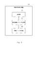
- FIG. 8 is a diagram illustrating a visualized map space.
- the dimensionality of the map space is two.
- Each node is represented as a square of squares.
- the display 42 shows information that can identify the material specification information 10 associated with the node. Specifically, in the example of FIG. 8, display 42 indicates material identification information.
- a reference position 44 represents a reference position.
- a region 46 represents a range in which the distance from the reference position 44 is equal to or less than the singular threshold.
- the node corresponding to the display 42 showing P109 is located outside the area 46. That is, the position of this node is the position where the distance from the reference position 44 is greater than the singularity threshold. Therefore, this node is detected as a singular node.
- the peculiar node detection unit 2060 may divide the nodes to which the material specification information 10 is assigned into a plurality of clusters and detect peculiar nodes for each cluster. For example, the peculiar node detection unit 2060 detects, for each node to which the material specification information 10 is assigned, multidimensional data (hereinafter referred to as a specification vector ). Then, the peculiar node detection unit 2060 divides the plurality of nodes to which the material specification information 10 is assigned into a plurality of clusters by clustering them based on the corresponding specification vectors. Any clustering algorithm such as the k-means method can be used as a specific clustering method.
- the specification vector may indicate values for all the parameters indicated by the material specification information 10, or may indicate values for some of the parameters. That is, if the number of dimensions of the specification vector is k, the value of k may be the same as the number of parameters indicated by the material specification information 10, or may be smaller than the number of parameters indicated by the material specification information 10.
- the material specification information 10 indicates both parameters that take continuous values (for example, the compounding ratio of substances) and parameters that do not take continuous values (for example, the type of processing).
- the specification vector is generated using only parameters that take continuous values.
- the specification vector may indicate the value of the parameter indicated by the material specification information 10 as it is, or the value of each parameter may be converted by a predetermined method (for example, normalization or standardization). You may indicate the value obtained by
- the clustering method is not limited to the method using the specification vector.
- the singular node detection unit 2060 may cluster nodes based on the type of material indicated by the material specification information 10 .
- different types of materials 60 such as a material 60 classified as carbon fiber reinforced plastic and a material 60 classified as stainless steel are included. may include those shown. Therefore, the peculiar node detection unit 2060 classifies the nodes into clusters for each type of material 60 indicated by the assigned material specification information 10 . Thereby, a singular node can be detected for each type of material 60 .
- the peculiar node detection unit 2060 may further apply clustering based on the specification vector to each cluster.
- the peculiar node detection unit 2060 calculates the reference position i and the peculiar threshold i based on the positions of each of the plurality of nodes included in the cluster i among the nodes to which the material specification information 10 is assigned.
- the calculation method the same method as in the case where clustering is not performed can be adopted. That is, for example, the peculiar node detection unit 2060 calculates the centroid position and the geometric center of the positions of a plurality of nodes included in the cluster i among the nodes to which the material specification information 10 is assigned, and calculates This position is treated as the reference position i.
- the singular node detection unit 2060 calculates a statistic value representing the size of the distribution of the positions of a plurality of nodes included in the cluster i among the nodes to which the material specification information 10 is assigned, The statistic value or a value obtained by multiplying the statistic value by a predetermined positive real number is treated as the singular threshold i.
- the peculiar node detection unit 2060 determines whether the distance between the position of each node included in the cluster i and the reference position i is greater than the peculiar threshold i, among the nodes to which the material specification information 10 is assigned. determine whether Then, the peculiar node detection unit 2060 detects a node whose distance from the reference position i is greater than the peculiar threshold i as a peculiar node in the cluster i.
- FIG. 9 is a diagram illustrating a case of detecting singular nodes from each of a plurality of clusters.
- the nodes assigned with the material specification information 10 are divided into two clusters.
- Nodes classified into cluster 1 are indicated by solid lines in the display 42 .
- nodes classified into cluster 2 are indicated by dotted lines in the display 42 .
- a reference position 44-1 represents the reference position calculated for cluster 1.
- a region 46-1 represents a range in which the distance from the reference position 44-1 is equal to or less than the peculiar threshold value calculated for cluster 1.
- the reference position 44-2 represents the reference position calculated for cluster 2.
- a region 46-2 represents a range in which the distance from the reference position 44-2 is equal to or less than the peculiar threshold value calculated for cluster 2.
- FIG. Here, all nodes classified into cluster 2 are located in region 46-2. Therefore, no peculiar node is detected from cluster 2 .
- the peculiar material detection device 2000 performs clustering based on material specifications, and detects peculiar nodes for each cluster. By doing so, it is possible to detect the materials 60 that can produce a unique product 70 from among the materials 60 that are similar to each other.
- the peculiar material detection device 2000 outputs output information representing the processing result.
- the output information includes information that enables understanding of the detected singular node.
- Information from which the detected peculiar nodes can be grasped includes, for example, an image representing the visualized map space (hereinafter referred to as a map image) and screen data including the image.
- a map image generation unit the functional configuration unit that generates the map image.
- FIG. 10 is a diagram illustrating a map image in which singular nodes are highlighted. Note that the map image 40 of FIG. 10 is the same as that of FIG. 8 except that the display 42 corresponding to the singular node is highlighted.
- the singular node is a node with material identification information of P109. Therefore, the display 42 attached to this node is larger in size and has a thicker border than the other displays 42 .
- the map image 40 may include information on material specifications and physical properties associated with the singular node.
- FIG. 11 is a diagram illustrating a map image 40 containing information on material specifications and physical properties corresponding to singular nodes.
- the content of FIG. 11 is the same as that of FIG. 10, except that the content of display 42 is different from that shown in FIG.
- the display 42 of the peculiar node shows the material identification information "P109" and the material specifications of the compounding ratio of substances A to C as the contents of the material specification information 10 corresponding to the peculiar node.
- the display 42 of the singular node indicates the physical quantity of each of the physical properties U, V, and W as the content of the physical property corresponding to the singular node.
- the screen data including the map image 40 is included in the output information
- an input from the user may be received on the screen represented by the screen data, and information regarding the node may be output according to the input.
- the map image 40 illustrated in FIG. 10 is shown on the screen that is first output to the display device of the terminal used by the user. That is, the content of the display 42 of each node is made material identification information.
- the display 42 for that node is displayed as illustrated in FIG. As shown in 42, the display is changed to display 42 showing the details of material specifications and physical properties.
- the value of each element of the physical property vector assigned to the node may not represent the physical property amount as it is, but may be converted by normalization or the like.
- the peculiar material detection apparatus 2000 converts the value of the element of the physical property vector into a physical property amount for the node designated by the user, and includes the physical property amount obtained by the conversion in the display 42.
- the output information is not limited to the map image 40 or a screen containing the map image.
- the output information is text information indicating information such as the position on the map space, the contents of the assigned material specification information 10, and the physical properties of the product 70 represented by the assigned physical property vector for the singular node.
- the output information may further indicate the degree of peculiarity based on the position on the map space for the peculiar node.
- the degree of peculiarity can be represented by a value obtained by dividing the distance between the peculiar node and the reference position by the peculiarity threshold. This degree of singularity may be indicated on the map image 40 .
- the output mode of the output information is arbitrary.
- the peculiar material detection device 2000 stores output information in any storage device accessible from the peculiar material detection device 2000 .
- the peculiar material detection device 2000 displays output information on any display device that can be controlled from the peculiar material detection device 2000 .
- the peculiar material detection device 2000 transmits output information to any device communicably connected to the peculiar material detection device 2000 .
- Non-transitory computer readable media include various types of tangible storage media.
- Examples of non-transitory computer-readable media include magnetic recording media (e.g., floppy disks, magnetic tapes, hard disk drives), magneto-optical recording media (e.g., magneto-optical discs), CD-ROMs, CD-Rs, CD-Rs /W, including semiconductor memory (e.g. mask ROM, PROM (programmable ROM), EPROM (erasable PROM), flash ROM, RAM);
- the program may also be provided to the computer on various types of transitory computer readable medium. Examples of transitory computer-readable media include electrical signals, optical signals, and electromagnetic waves. Transitory computer-readable media can deliver the program to the computer via wired channels, such as wires and optical fibers, or wireless channels.
- Each of the material specification information is assigned to one of the nodes based on the physical property information corresponding to the material specification information, and among the nodes to which the material specification information is assigned, in the map space and a singular node detection means for detecting a singular node at a singular position.
- the singular node detection means assigns each of the plurality of material specification information to the node to which the physical property vector most similar to the physical property vector obtained from the physical property information corresponding to the material specification information is assigned.
- Supplementary note 1 the specific material detection device.
- the singular node detection means is dividing the plurality of nodes to which the material specification information is assigned into a plurality of clusters based on the material specification information; any one of Appendices 1 to 4, wherein for each of the plurality of clusters, the singular node is detected from among the nodes belonging to the cluster based on the distribution of the positions of the nodes included in the cluster on the map space;
- the specific material detection device according to item 1.
- the peculiar material detection device according to any one of Appendices 1 to 5, wherein the map image includes a display indicating the peculiar node.
- the display indicating the singular node is either one of material specifications represented by the material specification information assigned to the singular node and physical properties represented by the physical property vector assigned to the singular node. or both.
- a control method implemented by a computer comprising: For each of a plurality of patterns of materials that can be used in the target process, material specification information that represents the material specifications of the material, and physical property amounts for each of the multiple physical properties of the deliverable that can be generated in the process using the material an acquisition step of acquiring physical property information indicating Using the physical property information, a self-organizing map is generated in which each node is assigned a position on the map space and a physical property vector indicating a physical property amount of each of a plurality of types of physical properties of the product.
- Each of the material specification information is assigned to one of the nodes based on the physical property information corresponding to the material specification information, and among the nodes to which the material specification information is assigned, in the map space a singular node detection step of detecting a singular node at a singular position.
- a singular node detection step of detecting a singular node at a singular position.
- the display indicating the singular node is either one of material specifications represented by the material specification information assigned to the singular node and physical properties represented by the physical property vector assigned to the singular node. or both.
- (Appendix 15) to the computer For each of a plurality of patterns of materials that can be used in the target process, material specification information that represents the material specifications of the material, and physical property amounts for each of the multiple physical properties of the deliverable that can be generated in the process using the material an acquisition step of acquiring physical property information indicating Using the physical property information, a self-organizing map is generated in which each node is assigned a position on the map space and a physical property vector indicating a physical property amount of each of a plurality of types of physical properties of the product.
- Each of the material specification information is assigned to one of the nodes based on the physical property information corresponding to the material specification information, and among the nodes to which the material specification information is assigned, in the map space and a singular node detection step of detecting singular nodes at singular locations.
- each of the plurality of material specification information is assigned to the node to which the physical property vector most similar to the physical property vector obtained from the physical property information corresponding to the material specification information is assigned.
- Material specification information 20 Physical property information 30 Self-organizing map 40 Map image 42 Display 44 Reference position 46 Area 60 Material 70 Product 100 Table 102 Material identification information 104 Material specification 200 Table 202 Product identification information 204 Physical property 300 Table 302 Position 304 Physical property vector 306 Material identification information 500 Computer 502 Bus 504 Processor 506 Memory 508 Storage device 510 Input/output interface 512 Network interface 2000 Unique material detection device 2020 Acquisition unit 2040 Self-organizing map generation unit 2060 Unique node detection unit
Landscapes
- Engineering & Computer Science (AREA)
- Physics & Mathematics (AREA)
- Theoretical Computer Science (AREA)
- General Physics & Mathematics (AREA)
- Computing Systems (AREA)
- Geometry (AREA)
- Evolutionary Computation (AREA)
- General Engineering & Computer Science (AREA)
- Life Sciences & Earth Sciences (AREA)
- General Health & Medical Sciences (AREA)
- Software Systems (AREA)
- Computational Linguistics (AREA)
- Data Mining & Analysis (AREA)
- Biomedical Technology (AREA)
- Artificial Intelligence (AREA)
- Molecular Biology (AREA)
- Health & Medical Sciences (AREA)
- Biophysics (AREA)
- Mathematical Physics (AREA)
- Automation & Control Theory (AREA)
- Aviation & Aerospace Engineering (AREA)
- Computational Mathematics (AREA)
- Mathematical Analysis (AREA)
- Mathematical Optimization (AREA)
- Pure & Applied Mathematics (AREA)
- Computer Hardware Design (AREA)
- Computer Vision & Pattern Recognition (AREA)
- Bioinformatics & Computational Biology (AREA)
- Bioinformatics & Cheminformatics (AREA)
- Management, Administration, Business Operations System, And Electronic Commerce (AREA)
Abstract
Description
<概要>
図1は、実施形態1の特異材料検出装置2000の動作の概要を例示する図である。ここで、図1は、特異材料検出装置2000の概要の理解を容易にするための図であり、特異材料検出装置2000の動作は、図1に示したものに限定されない。 [Embodiment 1]
<Overview>
FIG. 1 is a diagram illustrating an overview of the operation of the specific
試行錯誤しながら製品開発を行う中で、まれに、特異な物性を持つ成果物が得られることがある。このような特異な成果物は、その研究などを通じて新たな原理、添加、又は性質などの発見につながる可能性があることから、重要なものであるといえる。 <Example of action and effect>
During product development through trial and error, on rare occasions, products with unique physical properties are obtained. Such peculiar products can be said to be important because they may lead to the discovery of new principles, additions, or properties through their research.
図2は、実施形態1の特異材料検出装置2000の機能構成を例示するブロック図である。特異材料検出装置2000は、取得部2020、自己組織化マップ生成部2040、及び特異ノード検出部2060を有する。取得部2020は、複数パターンの材料60それぞれについて、材料諸元情報10及び物性情報20を取得する。自己組織化マップ生成部2040は、物性情報20を利用して自己組織化マップ30を生成する。特異ノード検出部は、各材料諸元情報10を自己組織化マップ30の各ノードに対して割り当てる。さらに、特異ノード検出部2060は、材料諸元情報10が割り当てられているノードのうち、マップ空間におけるそれらの分布において特異な位置にあるノードを、特異ノードとして検出する。 <Example of functional configuration>
FIG. 2 is a block diagram illustrating the functional configuration of the specific
特異材料検出装置2000の各機能構成部は、各機能構成部を実現するハードウエア(例:ハードワイヤードされた電子回路など)で実現されてもよいし、ハードウエアとソフトウエアとの組み合わせ(例:電子回路とそれを制御するプログラムの組み合わせなど)で実現されてもよい。以下、特異材料検出装置2000の各機能構成部がハードウエアとソフトウエアとの組み合わせで実現される場合について、さらに説明する。 <Example of hardware configuration>
Each functional component of the peculiar
図4は、実施形態1の特異材料検出装置2000によって実行される処理の流れを例示するフローチャートである。取得部2020は、対象工程で利用されうる複数の材料60それぞれについて、材料諸元情報10及び物性情報20を取得する(S102)。自己組織化マップ生成部2040は、物性情報20を利用して、自己組織化マップ30を生成する(S104)。特異ノード検出部2060は、各材料諸元情報10を、自己組織化マップ30のいずれかのノードに対して割り当てる(S106)。特異ノード検出部2060は、材料諸元情報10が割り当てられているノードのうち、マップ空間におけるそれらの分布において特異な位置にあるノードを、特異ノードとして検出する(S108)。 <Process flow>
FIG. 4 is a flow chart illustrating the flow of processing executed by the specific
取得部2020は、対象工程において利用されうる複数パターンの材料60それぞれについて、その材料60の材料諸元を表す材料諸元情報10と、その材料60を用いて生成されうる成果物70についての物性情報20を取得する(S102)。図5は、材料諸元情報10をテーブル形式で例示する図である。図5のテーブル100は、材料識別情報102及び材料諸元104という列を有する。材料識別情報102は、材料60に割り当てられた識別情報を示す。材料諸元104は、材料60の諸元を示す。 <Acquisition of
The
自己組織化マップ生成部2040は、物性情報20を利用して自己組織化マップ30を生成する(S104)。自己組織化マップ30は、m次元のマップ空間上に配置された複数のノードを有する。マップ空間の次元数は、予め定められていてもよいし、ユーザによって指定されてもよい。 <Generation of Self-Organizing Map 30: S104>
The self-organizing
特異ノード検出部2060は、取得部2020によって取得された各材料諸元情報10を、自己組織化マップ30のいずれかのノードに割り当てる(S106)。具体的には、特異ノード検出部2060は、材料諸元情報10に対応する物性情報20から得られる物性ベクトルについて、その物性ベクトルと最も類似する物性ベクトルを持つノードを特定する。そして、特異ノード検出部2060は、その材料諸元情報10を、特定したノードに割り当てる。 <Assignment of material specification information 10: S106>
The peculiar
特異ノード検出部2060は、材料諸元情報10が割り当てられているノードの中から、特異ノードを検出する(S108)。特異ノードは、材料諸元情報10が割り当てられているノードのうち、マップ空間におけるそれらのノードの分布において特異な位置にあるノードである。 <Detection of singular node: S108>
The peculiar
図8の例では、材料諸元情報10が割り当てられている全てのノードの分布に着目して、特異ノードが検出されている。この点、特異ノード検出部2060は、材料諸元情報10が割り当てられているノードを複数のクラスタに分割し、クラスタごとに特異ノードを検出してもよい。例えば特異ノード検出部2060は、材料諸元情報10が割り当てられている各ノードに対し、その材料諸元情報10によって示される複数種類のパラメータそれぞれの値を表す多次元データ(以下、諸元ベクトル)を割り当てる。そして、特異ノード検出部2060は、材料諸元情報10が割り当てられている複数のノードを、対応する諸元ベクトルに基づいてクラスタリングすることによって、複数のクラスタに分割する。なお、クラスタリングの具体的な手法には、k-means 法などといった任意のクラスタリングアルゴリズムを利用できる。 <Node clustering>
In the example of FIG. 8, singular nodes are detected by focusing on the distribution of all nodes to which the
特異材料検出装置2000は、処理結果を表す出力情報を出力する。出力情報は、検出された特異ノードを把握可能な情報を含む。検出された特異ノードを把握可能な情報は、例えば、可視化されたマップ空間を表す画像(以下、マップ画像)や、その画像を含む画面のデータを含む。以下、マップ画像の生成を行う機能構成部を、マップ画像生成部と呼ぶ(図示せず)。 <Output of processing result>
The peculiar
(付記1)
対象の工程で利用されうる複数パターンの材料それぞれについて、その材料の材料諸元を表す材料諸元情報と、その材料を用いて前記工程で生成されうる成果物の複数の物性それぞれについての物性量を示す物性情報とを取得する取得手段と、
前記物性情報を用いて、マップ空間上の位置と、前記成果物の複数種類の物性それぞれの物性量に関する値を示す物性ベクトルとが各ノードに割り当てられている自己組織化マップを生成する自己組織化マップ生成手段と、
各前記材料諸元情報を、その材料諸元情報に対応する前記物性情報に基づいていずれかの前記ノードに割り当て、前記材料諸元情報が割り当てられている前記ノードの中から、前記マップ空間において特異な位置にある特異ノードを検出する特異ノード検出手段と、を有する特異材料検出装置。
(付記2)
前記特異ノード検出手段は、複数の前記材料諸元情報それぞれを、その材料諸元情報に対応する前記物性情報から得られる前記物性ベクトルと最も類似する前記物性ベクトルが割り当てられている前記ノードに割り当てる、付記1に記載の特異材料検出装置。
(付記3)
前記特異ノード検出手段は、前記材料諸元情報が割り当てられている各前記ノードのうち、前記マップ空間上の基準位置からの距離が閾値より大きい前記ノードを、前記特異ノードとして検出する、付記1又は2に記載の特異材料検出装置。
(付記4)
前記特異ノード検出手段は、
前記材料諸元情報が割り当てられている複数の前記ノードの重心位置又は幾何中心を前記基準位置として利用し、
前記材料諸元情報が割り当てられている複数の前記ノードの位置の分布の大きさを表す統計値、又はその統計値に所定の正の実数を掛けた値を、前記閾値として利用する、付記3に記載の特異材料検出装置。
(付記5)
前記特異ノード検出手段は、
前記材料諸元情報が割り当てられている複数の前記ノードを、前記材料諸元情報に基づいて複数のクラスタに分割し、
複数の前記クラスタそれぞれについて、そのクラスタに含まれる各前記ノードの前記マップ空間上の位置の分布に基づいて、そのクラスタに属する前記ノードの中から前記特異ノードを検出する、付記1から4いずれか一項に記載の特異材料検出装置。
(付記6)
前記マップ空間上に配置されている各前記ノードを表すマップ画像を生成するマップ画像生成手段を有し、
前記マップ画像は、前記特異ノードを示す表示を含む、付記1から5いずれか一項に記載の特異材料検出装置。
(付記7)
前記特異ノードを示す表示は、その特異ノードに割り当てられている前記材料諸元情報によって表される材料諸元、及びその特異ノードに割り当てられている前記物性ベクトルによって表される物性のいずれか一方又は双方を示す、付記6に記載の特異材料検出装置。
(付記8)
コンピュータによって実行される制御方法であって、
対象の工程で利用されうる複数パターンの材料それぞれについて、その材料の材料諸元を表す材料諸元情報と、その材料を用いて前記工程で生成されうる成果物の複数の物性それぞれについての物性量を示す物性情報とを取得する取得ステップと、
前記物性情報を用いて、マップ空間上の位置と、前記成果物の複数種類の物性それぞれの物性量に関する値を示す物性ベクトルとが各ノードに割り当てられている自己組織化マップを生成する自己組織化マップ生成ステップと、
各前記材料諸元情報を、その材料諸元情報に対応する前記物性情報に基づいていずれかの前記ノードに割り当て、前記材料諸元情報が割り当てられている前記ノードの中から、前記マップ空間において特異な位置にある特異ノードを検出する特異ノード検出ステップと、を有する制御方法。
(付記9)
前記特異ノード検出ステップにおいて、複数の前記材料諸元情報それぞれを、その材料諸元情報に対応する前記物性情報から得られる前記物性ベクトルと最も類似する前記物性ベクトルが割り当てられている前記ノードに割り当てる、付記8に記載の制御方法。
(付記10)
前記特異ノード検出ステップにおいて、前記材料諸元情報が割り当てられている各前記ノードのうち、前記マップ空間上の基準位置からの距離が閾値より大きい前記ノードを、前記特異ノードとして検出する、付記8又は9に記載の制御方法。
(付記11)
前記特異ノード検出ステップにおいて、
前記材料諸元情報が割り当てられている複数の前記ノードの重心位置又は幾何中心を前記基準位置として利用し、
前記材料諸元情報が割り当てられている複数の前記ノードの位置の分布の大きさを表す統計値、又はその統計値に所定の正の実数を掛けた値を、前記閾値として利用する、付記10に記載の制御方法。
(付記12)
前記特異ノード検出ステップにおいて、
前記材料諸元情報が割り当てられている複数の前記ノードを、前記材料諸元情報に基づいて複数のクラスタに分割し、
複数の前記クラスタそれぞれについて、そのクラスタに含まれる各前記ノードの前記マップ空間上の位置の分布に基づいて、そのクラスタに属する前記ノードの中から前記特異ノードを検出する、付記8から11いずれか一項に記載の制御方法。
(付記13)
前記マップ空間上に配置されている各前記ノードを表すマップ画像を生成するマップ画像生成ステップを有し、
前記マップ画像は、前記特異ノードを示す表示を含む、付記8から12いずれか一項に記載の制御方法。
(付記14)
前記特異ノードを示す表示は、その特異ノードに割り当てられている前記材料諸元情報によって表される材料諸元、及びその特異ノードに割り当てられている前記物性ベクトルによって表される物性のいずれか一方又は双方を示す、付記13に記載の制御方法。
(付記15)
コンピュータに、
対象の工程で利用されうる複数パターンの材料それぞれについて、その材料の材料諸元を表す材料諸元情報と、その材料を用いて前記工程で生成されうる成果物の複数の物性それぞれについての物性量を示す物性情報とを取得する取得ステップと、
前記物性情報を用いて、マップ空間上の位置と、前記成果物の複数種類の物性それぞれの物性量に関する値を示す物性ベクトルとが各ノードに割り当てられている自己組織化マップを生成する自己組織化マップ生成ステップと、
各前記材料諸元情報を、その材料諸元情報に対応する前記物性情報に基づいていずれかの前記ノードに割り当て、前記材料諸元情報が割り当てられている前記ノードの中から、前記マップ空間において特異な位置にある特異ノードを検出する特異ノード検出ステップと、を実行させる非一時的なコンピュータ可読媒体。
(付記16)
前記特異ノード検出ステップにおいて、複数の前記材料諸元情報それぞれを、その材料諸元情報に対応する前記物性情報から得られる前記物性ベクトルと最も類似する前記物性ベクトルが割り当てられている前記ノードに割り当てる、付記15に記載の非一時的なコンピュータ可読媒体。
(付記17)
前記特異ノード検出ステップにおいて、前記材料諸元情報が割り当てられている各前記ノードのうち、前記マップ空間上の基準位置からの距離が閾値より大きい前記ノードを、前記特異ノードとして検出する、付記15又は16に記載の非一時的なコンピュータ可読媒体。
(付記18)
前記特異ノード検出ステップにおいて、
前記材料諸元情報が割り当てられている複数の前記ノードの重心位置又は幾何中心を前記基準位置として利用し、
前記材料諸元情報が割り当てられている複数の前記ノードの位置の分布の大きさを表す統計値、又はその統計値に所定の正の実数を掛けた値を、前記閾値として利用する、付記17に記載の非一時的なコンピュータ可読媒体。
(付記19)
前記特異ノード検出ステップにおいて、
前記材料諸元情報が割り当てられている複数の前記ノードを、前記材料諸元情報に基づいて複数のクラスタに分割し、
複数の前記クラスタそれぞれについて、そのクラスタに含まれる各前記ノードの前記マップ空間上の位置の分布に基づいて、そのクラスタに属する前記ノードの中から前記特異ノードを検出する、付記15から18いずれか一項に記載の非一時的なコンピュータ可読媒体。
(付記20)
前記マップ空間上に配置されている各前記ノードを表すマップ画像を生成するマップ画像生成ステップを有し、
前記マップ画像は、前記特異ノードを示す表示を含む、付記15から19いずれか一項に記載の非一時的なコンピュータ可読媒体。
(付記21)
前記特異ノードを示す表示は、その特異ノードに割り当てられている前記材料諸元情報によって表される材料諸元、及びその特異ノードに割り当てられている前記物性ベクトルによって表される物性のいずれか一方又は双方を示す、付記20に記載の非一時的なコンピュータ可読媒体。 Some or all of the above-described embodiments can also be described in the following supplementary remarks, but are not limited to the following.
(Appendix 1)
For each of a plurality of patterns of materials that can be used in the target process, material specification information that represents the material specifications of the material, and physical property amounts for each of the multiple physical properties of the deliverable that can be generated in the process using the material Acquisition means for acquiring physical property information indicating
Using the physical property information, a self-organizing map is generated in which each node is assigned a position on the map space and a physical property vector indicating a physical property amount of each of a plurality of types of physical properties of the product. a transformation map generating means;
Each of the material specification information is assigned to one of the nodes based on the physical property information corresponding to the material specification information, and among the nodes to which the material specification information is assigned, in the map space and a singular node detection means for detecting a singular node at a singular position.
(Appendix 2)
The singular node detection means assigns each of the plurality of material specification information to the node to which the physical property vector most similar to the physical property vector obtained from the physical property information corresponding to the material specification information is assigned. , Supplementary note 1, the specific material detection device.
(Appendix 3)
Supplementary note 1, wherein the peculiar node detection means detects, as the peculiar node, among the nodes to which the material specification information is assigned, the node whose distance from a reference position on the map space is greater than a threshold value. Or the specific material detection device according to 2.
(Appendix 4)
The singular node detection means is
using the barycentric positions or geometric centers of the plurality of nodes to which the material specification information is assigned as the reference position;
Supplementary Note 3: A statistical value representing the size of the distribution of the positions of the plurality of nodes to which the material specification information is assigned, or a value obtained by multiplying the statistical value by a predetermined positive real number, is used as the threshold. The specific material detection device according to .
(Appendix 5)
The singular node detection means is
dividing the plurality of nodes to which the material specification information is assigned into a plurality of clusters based on the material specification information;
any one of Appendices 1 to 4, wherein for each of the plurality of clusters, the singular node is detected from among the nodes belonging to the cluster based on the distribution of the positions of the nodes included in the cluster on the map space; The specific material detection device according to item 1.
(Appendix 6)
map image generating means for generating a map image representing each of the nodes arranged on the map space;
6. The peculiar material detection device according to any one of Appendices 1 to 5, wherein the map image includes a display indicating the peculiar node.
(Appendix 7)
The display indicating the singular node is either one of material specifications represented by the material specification information assigned to the singular node and physical properties represented by the physical property vector assigned to the singular node. or both.
(Appendix 8)
A control method implemented by a computer, comprising:
For each of a plurality of patterns of materials that can be used in the target process, material specification information that represents the material specifications of the material, and physical property amounts for each of the multiple physical properties of the deliverable that can be generated in the process using the material an acquisition step of acquiring physical property information indicating
Using the physical property information, a self-organizing map is generated in which each node is assigned a position on the map space and a physical property vector indicating a physical property amount of each of a plurality of types of physical properties of the product. a transformation map generation step;
Each of the material specification information is assigned to one of the nodes based on the physical property information corresponding to the material specification information, and among the nodes to which the material specification information is assigned, in the map space a singular node detection step of detecting a singular node at a singular position.
(Appendix 9)
In the singular node detection step, each of the plurality of material specification information is assigned to the node to which the physical property vector most similar to the physical property vector obtained from the physical property information corresponding to the material specification information is assigned. , Supplementary Note 8.
(Appendix 10)
Supplementary note 8, wherein in the peculiar node detection step, among the nodes to which the material specification information is assigned, the node whose distance from a reference position on the map space is greater than a threshold is detected as the peculiar node. Or the control method according to 9.
(Appendix 11)
In the singular node detection step,
using the barycentric positions or geometric centers of the plurality of nodes to which the material specification information is assigned as the reference position;
Supplementary note 10: A statistical value representing the size of the distribution of the positions of the plurality of nodes to which the material specification information is assigned, or a value obtained by multiplying the statistical value by a predetermined positive real number, is used as the threshold value. The control method described in .
(Appendix 12)
In the singular node detection step,
dividing the plurality of nodes to which the material specification information is assigned into a plurality of clusters based on the material specification information;
Any one of Appendices 8 to 11, wherein for each of the plurality of clusters, the singular node is detected from among the nodes belonging to the cluster based on the distribution of the positions of the nodes included in the cluster on the map space. 1. The control method according to item 1.
(Appendix 13)
a map image generating step of generating a map image representing each of the nodes arranged on the map space;
13. The control method according to any one of Appendices 8 to 12, wherein the map image includes a display showing the singular node.
(Appendix 14)
The display indicating the singular node is either one of material specifications represented by the material specification information assigned to the singular node and physical properties represented by the physical property vector assigned to the singular node. or both.
(Appendix 15)
to the computer,
For each of a plurality of patterns of materials that can be used in the target process, material specification information that represents the material specifications of the material, and physical property amounts for each of the multiple physical properties of the deliverable that can be generated in the process using the material an acquisition step of acquiring physical property information indicating
Using the physical property information, a self-organizing map is generated in which each node is assigned a position on the map space and a physical property vector indicating a physical property amount of each of a plurality of types of physical properties of the product. a transformation map generation step;
Each of the material specification information is assigned to one of the nodes based on the physical property information corresponding to the material specification information, and among the nodes to which the material specification information is assigned, in the map space and a singular node detection step of detecting singular nodes at singular locations.
(Appendix 16)
In the singular node detection step, each of the plurality of material specification information is assigned to the node to which the physical property vector most similar to the physical property vector obtained from the physical property information corresponding to the material specification information is assigned. 16. The non-transitory computer-readable medium of claim 15.
(Appendix 17)
Supplementary note 15, in the peculiar node detection step, among the nodes to which the material specification information is assigned, the node whose distance from the reference position on the map space is greater than a threshold is detected as the peculiar node. Or the non-transitory computer readable medium according to 16.
(Appendix 18)
In the singular node detection step,
using the centroid positions or geometric centers of the plurality of nodes to which the material specification information is assigned as the reference position;
Supplementary Note 17: A statistical value representing the size of the distribution of the positions of the plurality of nodes to which the material specification information is assigned, or a value obtained by multiplying the statistical value by a predetermined positive real number, is used as the threshold. A non-transitory computer-readable medium as described in .
(Appendix 19)
In the singular node detection step,
dividing the plurality of nodes to which the material specification information is assigned into a plurality of clusters based on the material specification information;
any one of Appendices 15 to 18, wherein for each of the plurality of clusters, the singular node is detected from among the nodes belonging to the cluster based on the distribution of the positions of the nodes included in the cluster on the map space; A non-transitory computer-readable medium according to claim 1.
(Appendix 20)
a map image generating step of generating a map image representing each of the nodes arranged on the map space;
20. The non-transitory computer-readable medium of any one of Clauses 15-19, wherein the map image includes an indication of the singular node.
(Appendix 21)
The display indicating the singular node is either one of material specifications represented by the material specification information assigned to the singular node and physical properties represented by the physical property vector assigned to the singular node. or both.
20 物性情報
30 自己組織化マップ
40 マップ画像
42 表示
44 基準位置
46 領域
60 材料
70 成果物
100 テーブル
102 材料識別情報
104 材料諸元
200 テーブル
202 成果物識別情報
204 物性
300 テーブル
302 位置
304 物性ベクトル
306 材料識別情報
500 コンピュータ
502 バス
504 プロセッサ
506 メモリ
508 ストレージデバイス
510 入出力インタフェース
512 ネットワークインタフェース
2000 特異材料検出装置
2020 取得部
2040 自己組織化マップ生成部
2060 特異ノード検出部 10
Claims (21)
- 対象の工程で利用されうる複数パターンの材料それぞれについて、その材料の材料諸元を表す材料諸元情報と、その材料を用いて前記工程で生成されうる成果物の複数の物性それぞれについての物性量を示す物性情報とを取得する取得手段と、
前記物性情報を用いて、マップ空間上の位置と、前記成果物の複数種類の物性それぞれの物性量に関する値を示す物性ベクトルとが各ノードに割り当てられている自己組織化マップを生成する自己組織化マップ生成手段と、
各前記材料諸元情報を、その材料諸元情報に対応する前記物性情報に基づいていずれかの前記ノードに割り当て、前記材料諸元情報が割り当てられている前記ノードの中から、前記マップ空間において特異な位置にある特異ノードを検出する特異ノード検出手段と、を有する特異材料検出装置。 For each of a plurality of patterns of materials that can be used in the target process, material specification information that represents the material specifications of the material, and physical property amounts for each of the multiple physical properties of the deliverable that can be generated in the process using the material Acquisition means for acquiring physical property information indicating
Using the physical property information, a self-organizing map is generated in which each node is assigned a position on the map space and a physical property vector indicating a physical property amount of each of a plurality of types of physical properties of the product. a transformation map generating means;
Each of the material specification information is assigned to one of the nodes based on the physical property information corresponding to the material specification information, and among the nodes to which the material specification information is assigned, in the map space and a singular node detection means for detecting a singular node at a singular position. - 前記特異ノード検出手段は、複数の前記材料諸元情報それぞれを、その材料諸元情報に対応する前記物性情報から得られる前記物性ベクトルと最も類似する前記物性ベクトルが割り当てられている前記ノードに割り当てる、請求項1に記載の特異材料検出装置。 The singular node detection means assigns each of the plurality of material specification information to the node to which the physical property vector most similar to the physical property vector obtained from the physical property information corresponding to the material specification information is assigned. , The specific material detection device according to claim 1.
- 前記特異ノード検出手段は、前記材料諸元情報が割り当てられている各前記ノードのうち、前記マップ空間上の基準位置からの距離が閾値より大きい前記ノードを、前記特異ノードとして検出する、請求項1又は2に記載の特異材料検出装置。 3. The peculiar node detection means detects, as the peculiar node, among the nodes to which the material specification information is assigned, the node whose distance from a reference position on the map space is greater than a threshold. 3. The specific material detection device according to 1 or 2.
- 前記特異ノード検出手段は、
前記材料諸元情報が割り当てられている複数の前記ノードの重心位置又は幾何中心を前記基準位置として利用し、
前記材料諸元情報が割り当てられている複数の前記ノードの位置の分布の大きさを表す統計値、又はその統計値に所定の正の実数を掛けた値を、前記閾値として利用する、請求項3に記載の特異材料検出装置。 The singular node detection means is
using the barycentric positions or geometric centers of the plurality of nodes to which the material specification information is assigned as the reference position;
A statistical value representing the size of the distribution of the positions of the plurality of nodes to which the material specification information is assigned, or a value obtained by multiplying the statistical value by a predetermined positive real number is used as the threshold value. 4. The specific material detection device according to 3. - 前記特異ノード検出手段は、
前記材料諸元情報が割り当てられている複数の前記ノードを、前記材料諸元情報に基づいて複数のクラスタに分割し、
複数の前記クラスタそれぞれについて、そのクラスタに含まれる各前記ノードの前記マップ空間上の位置の分布に基づいて、そのクラスタに属する前記ノードの中から前記特異ノードを検出する、請求項1から4いずれか一項に記載の特異材料検出装置。 The singular node detection means is
dividing the plurality of nodes to which the material specification information is assigned into a plurality of clusters based on the material specification information;
5. Any one of claims 1 to 4, wherein for each of the plurality of clusters, the singular node is detected from among the nodes belonging to the cluster based on the distribution of the positions of the nodes included in the cluster on the map space. or the specific material detection device according to claim 1. - 前記マップ空間上に配置されている各前記ノードを表すマップ画像を生成するマップ画像生成手段を有し、
前記マップ画像は、前記特異ノードを示す表示を含む、請求項1から5いずれか一項に記載の特異材料検出装置。 map image generating means for generating a map image representing each of the nodes arranged on the map space;
The peculiar material detection device according to any one of claims 1 to 5, wherein the map image includes a display showing the peculiar node. - 前記特異ノードを示す表示は、その特異ノードに割り当てられている前記材料諸元情報によって表される材料諸元、及びその特異ノードに割り当てられている前記物性ベクトルによって表される物性のいずれか一方又は双方を示す、請求項6に記載の特異材料検出装置。 The display indicating the singular node is either one of material specifications represented by the material specification information assigned to the singular node and physical properties represented by the physical property vector assigned to the singular node. or both.
- コンピュータによって実行される制御方法であって、
対象の工程で利用されうる複数パターンの材料それぞれについて、その材料の材料諸元を表す材料諸元情報と、その材料を用いて前記工程で生成されうる成果物の複数の物性それぞれについての物性量を示す物性情報とを取得する取得ステップと、
前記物性情報を用いて、マップ空間上の位置と、前記成果物の複数種類の物性それぞれの物性量に関する値を示す物性ベクトルとが各ノードに割り当てられている自己組織化マップを生成する自己組織化マップ生成ステップと、
各前記材料諸元情報を、その材料諸元情報に対応する前記物性情報に基づいていずれかの前記ノードに割り当て、前記材料諸元情報が割り当てられている前記ノードの中から、前記マップ空間において特異な位置にある特異ノードを検出する特異ノード検出ステップと、を有する制御方法。 A control method implemented by a computer, comprising:
For each of a plurality of patterns of materials that can be used in the target process, material specification information that represents the material specifications of the material, and physical property amounts for each of the multiple physical properties of the deliverable that can be generated in the process using the material an acquisition step of acquiring physical property information indicating
Using the physical property information, a self-organizing map is generated in which each node is assigned a position on the map space and a physical property vector indicating a physical property amount of each of a plurality of types of physical properties of the product. a transformation map generation step;
Each of the material specification information is assigned to one of the nodes based on the physical property information corresponding to the material specification information, and among the nodes to which the material specification information is assigned, in the map space a singular node detection step of detecting a singular node at a singular position. - 前記特異ノード検出ステップにおいて、複数の前記材料諸元情報それぞれを、その材料諸元情報に対応する前記物性情報から得られる前記物性ベクトルと最も類似する前記物性ベクトルが割り当てられている前記ノードに割り当てる、請求項8に記載の制御方法。 In the singular node detection step, each of the plurality of material specification information is assigned to the node to which the physical property vector most similar to the physical property vector obtained from the physical property information corresponding to the material specification information is assigned. 9. The control method according to claim 8.
- 前記特異ノード検出ステップにおいて、前記材料諸元情報が割り当てられている各前記ノードのうち、前記マップ空間上の基準位置からの距離が閾値より大きい前記ノードを、前記特異ノードとして検出する、請求項8又は9に記載の制御方法。 3. In the singular node detection step, among the nodes to which the material specification information is assigned, the node whose distance from a reference position on the map space is greater than a threshold is detected as the singular node. 9. The control method according to 8 or 9.
- 前記特異ノード検出ステップにおいて、
前記材料諸元情報が割り当てられている複数の前記ノードの重心位置又は幾何中心を前記基準位置として利用し、
前記材料諸元情報が割り当てられている複数の前記ノードの位置の分布の大きさを表す統計値、又はその統計値に所定の正の実数を掛けた値を、前記閾値として利用する、請求項10に記載の制御方法。 In the singular node detection step,
using the barycentric positions or geometric centers of the plurality of nodes to which the material specification information is assigned as the reference position;
A statistical value representing the size of the distribution of the positions of the plurality of nodes to which the material specification information is assigned, or a value obtained by multiplying the statistical value by a predetermined positive real number is used as the threshold value. 11. The control method according to 10. - 前記特異ノード検出ステップにおいて、
前記材料諸元情報が割り当てられている複数の前記ノードを、前記材料諸元情報に基づいて複数のクラスタに分割し、
複数の前記クラスタそれぞれについて、そのクラスタに含まれる各前記ノードの前記マップ空間上の位置の分布に基づいて、そのクラスタに属する前記ノードの中から前記特異ノードを検出する、請求項8から11いずれか一項に記載の制御方法。 In the singular node detection step,
dividing the plurality of nodes to which the material specification information is assigned into a plurality of clusters based on the material specification information;
12. Any one of claims 8 to 11, wherein for each of the plurality of clusters, the singular node is detected from among the nodes belonging to the cluster based on the distribution of the positions of the nodes included in the cluster on the map space. or the control method according to item 1. - 前記マップ空間上に配置されている各前記ノードを表すマップ画像を生成するマップ画像生成ステップを有し、
前記マップ画像は、前記特異ノードを示す表示を含む、請求項8から12いずれか一項に記載の制御方法。 a map image generating step of generating a map image representing each of the nodes arranged on the map space;
13. The control method according to any one of claims 8 to 12, wherein said map image includes a display showing said singular node. - 前記特異ノードを示す表示は、その特異ノードに割り当てられている前記材料諸元情報によって表される材料諸元、及びその特異ノードに割り当てられている前記物性ベクトルによって表される物性のいずれか一方又は双方を示す、請求項13に記載の制御方法。 The display indicating the singular node is either one of material specifications represented by the material specification information assigned to the singular node and physical properties represented by the physical property vector assigned to the singular node. or both.
- コンピュータに、
対象の工程で利用されうる複数パターンの材料それぞれについて、その材料の材料諸元を表す材料諸元情報と、その材料を用いて前記工程で生成されうる成果物の複数の物性それぞれについての物性量を示す物性情報とを取得する取得ステップと、
前記物性情報を用いて、マップ空間上の位置と、前記成果物の複数種類の物性それぞれの物性量に関する値を示す物性ベクトルとが各ノードに割り当てられている自己組織化マップを生成する自己組織化マップ生成ステップと、
各前記材料諸元情報を、その材料諸元情報に対応する前記物性情報に基づいていずれかの前記ノードに割り当て、前記材料諸元情報が割り当てられている前記ノードの中から、前記マップ空間において特異な位置にある特異ノードを検出する特異ノード検出ステップと、を実行させる非一時的なコンピュータ可読媒体。 to the computer,
For each of a plurality of patterns of materials that can be used in the target process, material specification information that represents the material specifications of the material, and physical property amounts for each of the multiple physical properties of the deliverable that can be generated in the process using the material an acquisition step of acquiring physical property information indicating
Using the physical property information, a self-organizing map is generated in which each node is assigned a position on the map space and a physical property vector indicating a physical property amount of each of a plurality of types of physical properties of the product. a transformation map generation step;
Each of the material specification information is assigned to one of the nodes based on the physical property information corresponding to the material specification information, and among the nodes to which the material specification information is assigned, in the map space and a singular node detection step of detecting singular nodes at singular locations. - 前記特異ノード検出ステップにおいて、複数の前記材料諸元情報それぞれを、その材料諸元情報に対応する前記物性情報から得られる前記物性ベクトルと最も類似する前記物性ベクトルが割り当てられている前記ノードに割り当てる、請求項15に記載の非一時的なコンピュータ可読媒体。 In the singular node detection step, each of the plurality of material specification information is assigned to the node to which the physical property vector most similar to the physical property vector obtained from the physical property information corresponding to the material specification information is assigned. 16. The non-transitory computer-readable medium of claim 15.
- 前記特異ノード検出ステップにおいて、前記材料諸元情報が割り当てられている各前記ノードのうち、前記マップ空間上の基準位置からの距離が閾値より大きい前記ノードを、前記特異ノードとして検出する、請求項15又は16に記載の非一時的なコンピュータ可読媒体。 3. In the singular node detection step, among the nodes to which the material specification information is assigned, the node whose distance from a reference position on the map space is greater than a threshold is detected as the singular node. 17. The non-transitory computer readable medium of 15 or 16.
- 前記特異ノード検出ステップにおいて、
前記材料諸元情報が割り当てられている複数の前記ノードの重心位置又は幾何中心を前記基準位置として利用し、
前記材料諸元情報が割り当てられている複数の前記ノードの位置の分布の大きさを表す統計値、又はその統計値に所定の正の実数を掛けた値を、前記閾値として利用する、請求項17に記載の非一時的なコンピュータ可読媒体。 In the singular node detection step,
using the barycentric positions or geometric centers of the plurality of nodes to which the material specification information is assigned as the reference position;
A statistical value representing the size of the distribution of the positions of the plurality of nodes to which the material specification information is assigned, or a value obtained by multiplying the statistical value by a predetermined positive real number is used as the threshold value. 18. The non-transitory computer-readable medium of 17. - 前記特異ノード検出ステップにおいて、
前記材料諸元情報が割り当てられている複数の前記ノードを、前記材料諸元情報に基づいて複数のクラスタに分割し、
複数の前記クラスタそれぞれについて、そのクラスタに含まれる各前記ノードの前記マップ空間上の位置の分布に基づいて、そのクラスタに属する前記ノードの中から前記特異ノードを検出する、請求項15から18いずれか一項に記載の非一時的なコンピュータ可読媒体。 In the singular node detection step,
dividing the plurality of nodes to which the material specification information is assigned into a plurality of clusters based on the material specification information;
19. Any one of claims 15 to 18, wherein for each of the plurality of clusters, the singular node is detected from among the nodes belonging to the cluster based on the distribution of the positions of the nodes included in the cluster on the map space. or the non-transitory computer-readable medium of claim 1. - 前記マップ空間上に配置されている各前記ノードを表すマップ画像を生成するマップ画像生成ステップを有し、
前記マップ画像は、前記特異ノードを示す表示を含む、請求項15から19いずれか一項に記載の非一時的なコンピュータ可読媒体。 a map image generating step of generating a map image representing each of the nodes arranged on the map space;
20. The non-transitory computer-readable medium of any one of claims 15-19, wherein the map image includes a representation showing the singular node. - 前記特異ノードを示す表示は、その特異ノードに割り当てられている前記材料諸元情報によって表される材料諸元、及びその特異ノードに割り当てられている前記物性ベクトルによって表される物性のいずれか一方又は双方を示す、請求項20に記載の非一時的なコンピュータ可読媒体。 The display indicating the singular node is either one of material specifications represented by the material specification information assigned to the singular node and physical properties represented by the physical property vector assigned to the singular node. 21. The non-transitory computer-readable medium of claim 20, exhibiting either or both.
Priority Applications (4)
| Application Number | Priority Date | Filing Date | Title |
|---|---|---|---|
| JP2023506875A JPWO2022196208A5 (en) | 2022-02-14 | Unique material detection device, control method, and program | |
| CN202280022384.XA CN117043781A (en) | 2021-03-18 | 2022-02-14 | Singular material detection apparatus, control method, and non-transitory computer readable medium |
| EP22770967.2A EP4310718A1 (en) | 2021-03-18 | 2022-02-14 | Unique material detection device, control method, and non-transitory computer-readable medium |
| US18/282,145 US20240152664A1 (en) | 2021-03-18 | 2022-02-14 | Singular material detection apparatus, control method, and non-transitory computer readable medium |
Applications Claiming Priority (2)
| Application Number | Priority Date | Filing Date | Title |
|---|---|---|---|
| JP2021044487 | 2021-03-18 | ||
| JP2021-044487 | 2021-03-18 |
Publications (1)
| Publication Number | Publication Date |
|---|---|
| WO2022196208A1 true WO2022196208A1 (en) | 2022-09-22 |
Family
ID=83322234
Family Applications (1)
| Application Number | Title | Priority Date | Filing Date |
|---|---|---|---|
| PCT/JP2022/005625 WO2022196208A1 (en) | 2021-03-18 | 2022-02-14 | Unique material detection device, control method, and non-transitory computer-readable medium |
Country Status (4)
| Country | Link |
|---|---|
| US (1) | US20240152664A1 (en) |
| EP (1) | EP4310718A1 (en) |
| CN (1) | CN117043781A (en) |
| WO (1) | WO2022196208A1 (en) |
Citations (5)
| Publication number | Priority date | Publication date | Assignee | Title |
|---|---|---|---|---|
| JP2007087098A (en) * | 2005-09-22 | 2007-04-05 | Nissan Motor Co Ltd | Optimization system, optimization method, optimization program and program medium |
| JP2008293315A (en) * | 2007-05-25 | 2008-12-04 | Yokohama Rubber Co Ltd:The | Data analysis program, data analysis device, design program for structure, and design device for structure |
| JP2016099737A (en) * | 2014-11-19 | 2016-05-30 | 横浜ゴム株式会社 | Data analysis method and data display method |
| JP2016148988A (en) | 2015-02-12 | 2016-08-18 | 横浜ゴム株式会社 | Method for analyzing data and method for displaying data |
| JP2021044487A (en) | 2019-09-13 | 2021-03-18 | シーアンドディー セミコンダクター サービシーズ,インコーポレイテッド | Optimal exposure of bottom surface of substrate material and/or edges thereof for cleaning in spin coating device |
-
2022
- 2022-02-14 US US18/282,145 patent/US20240152664A1/en active Pending
- 2022-02-14 EP EP22770967.2A patent/EP4310718A1/en active Pending
- 2022-02-14 WO PCT/JP2022/005625 patent/WO2022196208A1/en active Application Filing
- 2022-02-14 CN CN202280022384.XA patent/CN117043781A/en active Pending
Patent Citations (5)
| Publication number | Priority date | Publication date | Assignee | Title |
|---|---|---|---|---|
| JP2007087098A (en) * | 2005-09-22 | 2007-04-05 | Nissan Motor Co Ltd | Optimization system, optimization method, optimization program and program medium |
| JP2008293315A (en) * | 2007-05-25 | 2008-12-04 | Yokohama Rubber Co Ltd:The | Data analysis program, data analysis device, design program for structure, and design device for structure |
| JP2016099737A (en) * | 2014-11-19 | 2016-05-30 | 横浜ゴム株式会社 | Data analysis method and data display method |
| JP2016148988A (en) | 2015-02-12 | 2016-08-18 | 横浜ゴム株式会社 | Method for analyzing data and method for displaying data |
| JP2021044487A (en) | 2019-09-13 | 2021-03-18 | シーアンドディー セミコンダクター サービシーズ,インコーポレイテッド | Optimal exposure of bottom surface of substrate material and/or edges thereof for cleaning in spin coating device |
Also Published As
| Publication number | Publication date |
|---|---|
| EP4310718A1 (en) | 2024-01-24 |
| CN117043781A (en) | 2023-11-10 |
| US20240152664A1 (en) | 2024-05-09 |
| JPWO2022196208A1 (en) | 2022-09-22 |
Similar Documents
| Publication | Publication Date | Title |
|---|---|---|
| US11055567B2 (en) | Unsupervised exception access detection method and apparatus based on one-hot encoding mechanism | |
| JP6654119B2 (en) | Plant data display processing device and plant control system | |
| US11334058B2 (en) | Plant data classification device, plant data display processing device, and plant control system | |
| JP6586764B2 (en) | Data analysis apparatus and data analysis method | |
| CN113853614A (en) | Unsupervised clustering using quantum similarity matrices in quantum feature space | |
| Aggarwal et al. | Characterization of hadoop jobs using unsupervised learning | |
| Yu et al. | Behavioral segmentation for human motion capture data based on graph cut method | |
| KR20150112832A (en) | Computing program, computing apparatus and computing method | |
| WO2022196208A1 (en) | Unique material detection device, control method, and non-transitory computer-readable medium | |
| CN114066261A (en) | Tampering detection method and device for electric meter, computer equipment and storage medium | |
| Shangguan et al. | Abnormal samples oversampling for anomaly detection based on uniform scale strategy and closed area | |
| CN115810419B (en) | Operation management method, device, equipment and storage medium for intelligent operating room | |
| Hu et al. | Shape-driven coordinate ordering for star glyph sets via reinforcement learning | |
| WO2022196206A1 (en) | Recommendation data generation device, control method, and non-transitory computer-readable medium | |
| WO2022196209A1 (en) | Physical property map image generation device, control method, and non-transitory computer readable medium | |
| WO2022196207A1 (en) | Map image generation device, control method, and non-transitory computer-readable medium | |
| WO2023181167A1 (en) | Map generation device, map generation method, and non-transitory computer-readable medium | |
| Cupek et al. | Improving KPI based performance analysis in discrete, multi-variant production | |
| Fan et al. | Robust visual tracking via bag of superpixels | |
| Fang et al. | A topology-preserving selection and clustering approach to multidimensional biological data | |
| WO2023195152A1 (en) | Recommendation data generation device, recommendation data generation method, and non-transitory computer-readable medium | |
| KR102289401B1 (en) | Apparatus and method for generating feature vector with label information | |
| KR20240028822A (en) | A method for training and operating Multi-sensor-based predictive model to provide customized solutions and an electronic device for performing said method | |
| JP2023122124A (en) | Information processing device, information processing method and information processing program | |
| Liu et al. | Quasiconformal Mahalanobis Distance-Based Kernel Mapping Machine Learning for Hyperspectral Data Classification |
Legal Events
| Date | Code | Title | Description |
|---|---|---|---|
| 121 | Ep: the epo has been informed by wipo that ep was designated in this application |
Ref document number: 22770967 Country of ref document: EP Kind code of ref document: A1 |
|
| WWE | Wipo information: entry into national phase |
Ref document number: 2023506875 Country of ref document: JP |
|
| WWE | Wipo information: entry into national phase |
Ref document number: 18282145 Country of ref document: US |
|
| WWE | Wipo information: entry into national phase |
Ref document number: 202280022384.X Country of ref document: CN |
|
| WWE | Wipo information: entry into national phase |
Ref document number: 2022770967 Country of ref document: EP |
|
| NENP | Non-entry into the national phase |
Ref country code: DE |
|
| ENP | Entry into the national phase |
Ref document number: 2022770967 Country of ref document: EP Effective date: 20231018 |