WO2022195984A1 - 情報処理装置、情報処理方法、及び情報処理プログラム - Google Patents
情報処理装置、情報処理方法、及び情報処理プログラム Download PDFInfo
- Publication number
- WO2022195984A1 WO2022195984A1 PCT/JP2021/045634 JP2021045634W WO2022195984A1 WO 2022195984 A1 WO2022195984 A1 WO 2022195984A1 JP 2021045634 W JP2021045634 W JP 2021045634W WO 2022195984 A1 WO2022195984 A1 WO 2022195984A1
- Authority
- WO
- WIPO (PCT)
- Prior art keywords
- information processing
- data
- partial area
- magnetic head
- seek
- Prior art date
- Legal status (The legal status is an assumption and is not a legal conclusion. Google has not performed a legal analysis and makes no representation as to the accuracy of the status listed.)
- Ceased
Links
Images

Classifications
-
- G—PHYSICS
- G06—COMPUTING OR CALCULATING; COUNTING
- G06F—ELECTRIC DIGITAL DATA PROCESSING
- G06F16/00—Information retrieval; Database structures therefor; File system structures therefor
- G06F16/20—Information retrieval; Database structures therefor; File system structures therefor of structured data, e.g. relational data
- G06F16/28—Databases characterised by their database models, e.g. relational or object models
-
- G—PHYSICS
- G11—INFORMATION STORAGE
- G11B—INFORMATION STORAGE BASED ON RELATIVE MOVEMENT BETWEEN RECORD CARRIER AND TRANSDUCER
- G11B20/00—Signal processing not specific to the method of recording or reproducing; Circuits therefor
- G11B20/10—Digital recording or reproducing
-
- G—PHYSICS
- G11—INFORMATION STORAGE
- G11B—INFORMATION STORAGE BASED ON RELATIVE MOVEMENT BETWEEN RECORD CARRIER AND TRANSDUCER
- G11B20/00—Signal processing not specific to the method of recording or reproducing; Circuits therefor
- G11B20/10—Digital recording or reproducing
- G11B20/12—Formatting, e.g. arrangement of data block or words on the record carriers
-
- G—PHYSICS
- G11—INFORMATION STORAGE
- G11B—INFORMATION STORAGE BASED ON RELATIVE MOVEMENT BETWEEN RECORD CARRIER AND TRANSDUCER
- G11B5/00—Recording by magnetisation or demagnetisation of a record carrier; Reproducing by magnetic means; Record carriers therefor
- G11B5/008—Recording on, or reproducing or erasing from, magnetic tapes, sheets, e.g. cards, or wires
Definitions
- the present disclosure relates to an information processing device, an information processing method, and an information processing program.
- Japanese Patent Application Laid-Open No. 2016-110669 discloses a technique of recording the head segment of each file, among segments obtained by dividing each of a plurality of files into a predetermined size, at a position where the seek distance of the magnetic head is short.
- Japanese Patent Application Laid-Open No. 2013-206518 discloses a technique of copying data to a position with the shortest average access distance when copying data recorded in a data partition to a cache partition.
- JP-A-2016-110669 does not consider recording data in multiple partitions of a magnetic tape. Further, the technique described in Japanese Patent Application Laid-Open No. 2013-206518 copies data within a magnetic tape, and does not consider adding new data.
- the present disclosure has been made in view of the circumstances described above, and aims to provide an information processing apparatus, an information processing method, and an information processing program capable of reducing the seek cost of the magnetic head.
- An information processing apparatus is an information processing apparatus that includes at least one processor, and the processor selects a partial area that minimizes the seek cost of the magnetic head from a plurality of partial areas into which the magnetic tape is divided. and control to record data in the selected partial area.
- the minimum seek cost of the magnetic head may be the shortest seek distance of the magnetic head.
- the minimum seek cost of the magnetic head may be the shortest seek time of the magnetic head.
- the processor when the free space of the selected partial area is less than the size of the data to be recorded, even if the processor reselects a partial area whose free space is equal to or greater than the size of the data to be recorded, good.
- a plurality of partial areas are associated with one logical volume, and the processor performs: A partial area that minimizes the seek cost of the magnetic head may be selected.
- the information processing method of the present disclosure selects a partial area that minimizes the seek cost of the magnetic head from among a plurality of partial areas into which the magnetic tape is divided, and performs control to record data in the selected partial area.
- the processing is executed by a processor included in the information processing device.
- the information processing program of the present disclosure selects a partial area that minimizes the seek cost of the magnetic head from among the plurality of partial areas into which the magnetic tape is divided, and performs control to record data in the selected partial area. It is for causing a processor included in the information processing apparatus to execute processing.
- the seek cost of the magnetic head can be reduced.
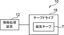
- FIG. 1 is a block diagram showing an example of the configuration of an information processing system;
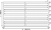
- FIG. It is a schematic diagram which shows an example of a magnetic tape.
- FIG. 4 is a diagram showing an example of the hardware constitutions of an information processing apparatus.
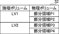
- FIG. 4 is a diagram showing an example of a volume management table;
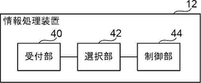
- FIG. 1 is a block diagram showing an example of a functional configuration of an information processing device;
- FIG. 4 is a diagram for explaining a data recording state;
- FIG. FIG. 10 is a diagram for explaining selection processing of a partial area;
- 4 is a flowchart showing an example of data recording processing;
- the information processing system 10 includes an information processing device 12 and a tape drive 18 .
- the information processing device 12 include a server computer and the like.
- a magnetic tape T as an example of a recording medium is stored in the tape drive 18 .
- a tape drive 18 is connected to the information processing device 12 .
- the tape drive 18 has a control device (not shown) including a processor, and writes data to or reads data from the magnetic tape T under the control of the information processing device 12 .
- An example of the magnetic tape T is an LTO (Linear Tape-Open) tape.
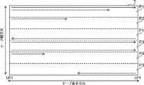
- the magnetic tape T is divided into a plurality of partial areas P1 to P4 along straight lines along the longitudinal direction of the magnetic tape T in which user data is recorded.
- the area in which user data is recorded is, for example, the area from LP (Logical Point) 3 to LP4 on the LTO tape.
- the partial areas P1 to P4 are collectively referred to as "partial area P".
- the partial area P corresponds to, for example, a partition obtained by dividing the area in which the user data of the magnetic tape T is recorded by the partition function defined by the LTO standard. Areas with the same number at the end of the code of the partial area P indicate the same partition. That is, FIG. 2 shows an example in which the magnetic tape T has four partitions. 2 represents the direction of data recording, that is, the direction of movement of the magnetic head relative to the magnetic tape T. As shown in FIG. Also, the numbers written above the solid line arrows in FIG. The number of partial regions P is not limited to the example in FIG. 2, and may be two, three, or five or more.
- the information processing device 12 includes a CPU (Central Processing Unit) 20, a memory 21 as a temporary storage area, and a non-volatile storage section 22.
- FIG. The information processing device 12 also includes a display 23 such as a liquid crystal display, an input device 24 such as a keyboard and a mouse, a network I/F (Interface) 25 connected to a network, and an external I/F 26 to which a tape drive 18 is connected.
- CPU 20 , memory 21 , storage unit 22 , display 23 , input device 24 , network I/F 25 and external I/F 26 are connected to bus 27 .
- the storage unit 22 is implemented by a HDD (Hard Disk Drive), SSD (Solid State Drive), flash memory, or the like.
- An information processing program 30 is stored in the storage unit 22 as a storage medium.
- the CPU 20 reads out the information processing program 30 from the storage unit 22 , expands it in the memory 21 , and executes the expanded information processing program 30 .
- the storage unit 22 also stores a volume management table 32 for associating logical volumes with physical volumes.
- An example of the volume management table 32 is shown in FIG.
- the volume management table 32 associates logical volumes with physical volumes.
- a logical volume is a logical storage area that is designated when data is recorded.
- a physical volume is a storage area in which data is physically recorded, and is partial areas P1 to P4 in this embodiment.
- FIG. 4 shows an example in which two partial areas P are associated with two logical volumes, the present invention is not limited to this. For example, four partial areas P may be associated with one logical volume.
- the information processing device 12 includes a reception section 40 , a selection section 42 and a control section 44 .
- the CPU 20 functions as a reception unit 40 , a selection unit 42 and a control unit 44 .
- the reception unit 40 receives data to be recorded and an instruction to record on the magnetic tape T transmitted from the user terminal.
- the selection unit 42 selects the partial area P that minimizes the seek cost of the magnetic head from among the plurality of partial areas P associated with the logical volume of the data recording destination received by the receiving unit 40 .
- the seek distance is used as the seek cost of the magnetic head, and the shorter the seek distance, the smaller the seek cost.
- the selection unit 42 selects the partial area P in which the seek distance of the magnetic head is the shortest. Seeking here means moving the magnetic head from a stop position to a position where writing is started.
- the method of specifying the logical volume as the recording destination of the data to be recorded is not particularly limited.
- a user operating a user terminal may designate a logical volume as a data recording destination.
- the selection unit 42 may select the logical volume of the data recording destination based on the data received by the reception unit 40 .
- the selection unit 42 selects a logical volume according to the type of data such as image data and document data.
- the selection unit 42 selects a logical volume according to the period during which data such as January data and February data was acquired.
- FIG. 6 shows the data recording state immediately before the selection unit 42 selects the partial area P.
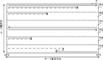
- FIG. 7 additionally shows the seek path of the magnetic head when data is additionally written in each partial area P in FIG.
- the solid arrows in FIGS. 6 and 7 represent the data recorded in each partial area P.
- the dashed-dotted arrows in FIG. 7 represent the seek paths of the magnetic head when data is additionally written in each partial area P.
- the dashed-dotted line arrows are slightly shifted from the solid line arrows. It is also assumed here that the stop position of the magnetic head is on the leading side (left side in FIGS. 6 and 7) of LP3 of the magnetic tape.
- the selection unit 42 selects the partial area P4.
- the selection unit 42 selects one partial area P from the plurality of partial areas P according to a preset rule. good too.
- Rules in this case include, for example, a rule of random selection, a rule of selecting the partial area P with the smallest assigned number, or a rule of selecting the partial area P with the largest free space. .
- the control unit 44 performs control to record the data received by the receiving unit 40 in the partial area P selected by the selecting unit 42 .
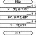
- the data recording process shown in FIG. 8 is executed by the CPU 20 executing the information processing program 30 .
- the data recording process shown in FIG. 8 is executed, for example, when the information processing apparatus 12 receives data to be recorded and an instruction to record on the magnetic tape T transmitted from the user terminal.
- the reception unit 40 receives the data to be recorded and the instruction to record on the magnetic tape T transmitted from the user terminal.
- the selection unit 42 selects the portion of the plurality of partial areas P associated with the logical volume as the recording destination of the data received in step S10, where the seek cost of the magnetic head is the minimum. Select region P.
- step S14 the control unit 44 performs control to record the data received in step S10 in the partial area P selected in step S12.
- the data recording process ends.
- the seek cost of the magnetic head can be reduced.
- the selection unit 42 reselects the partial area P whose free space is equal to or greater than the size of the data to be recorded. good too. In this case, for example, the selection unit 42 selects the partial area P with the lowest seek cost from among the partial areas P whose free space is equal to or greater than the size of the data to be recorded.
- the selection unit 42 selects the partial area P with the shortest seek distance of the magnetic head as the partial area P with the minimum seek cost of the magnetic head.
- the seek distance of the magnetic head is accompanied by a band change
- the seek distance is considered to be the shortest.
- the selection unit 42 may select the partial area P that minimizes the seek time of the magnetic head as the partial area P that minimizes the seek cost of the magnetic head.
- the functions of the reception unit 40, the selection unit 42, and the control unit 44 implemented by the CPU 20 may be implemented by a processor included in the control device of the tape drive 18.
- the hardware structure of the processing unit (processing unit) that executes various processes includes the following various processors ( processor) can be used.
- the various processors include, in addition to the CPU, which is a general-purpose processor that executes software (programs) and functions as various processing units, circuits such as FPGAs (Field Programmable Gate Arrays), etc.
- Programmable Logic Device (PLD) which is a processor whose configuration can be changed, ASIC (Application Specific Integrated Circuit) etc. Circuits, etc. are included.
- One processing unit may be composed of one of these various processors, or a combination of two or more processors of the same type or different types (for example, a combination of multiple FPGAs, a combination of a CPU and an FPGA). combination). Also, a plurality of processing units may be configured by one processor.
- a single processor is configured by combining one or more CPUs and software.
- a processor functions as multiple processing units.
- SoC System on Chip
- the various processing units are configured using one or more of the above various processors as a hardware structure.
- an electric circuit combining circuit elements such as semiconductor elements can be used.
- the information processing program 30 has been pre-stored (installed) in the storage unit 22, but the present invention is not limited to this.
- the information processing program 30 is provided in a form recorded on a recording medium such as a CD-ROM (Compact Disc Read Only Memory), a DVD-ROM (Digital Versatile Disc Read Only Memory), and a USB (Universal Serial Bus) memory. good too. Further, the information processing program 30 may be downloaded from an external device via a network.
Landscapes
- Engineering & Computer Science (AREA)
- Databases & Information Systems (AREA)
- Theoretical Computer Science (AREA)
- Signal Processing (AREA)
- Data Mining & Analysis (AREA)
- Physics & Mathematics (AREA)
- General Engineering & Computer Science (AREA)
- General Physics & Mathematics (AREA)
- Signal Processing For Digital Recording And Reproducing (AREA)
Priority Applications (1)
| Application Number | Priority Date | Filing Date | Title |
|---|---|---|---|
| JP2023506750A JPWO2022195984A1 (enExample) | 2021-03-18 | 2021-12-10 |
Applications Claiming Priority (2)
| Application Number | Priority Date | Filing Date | Title |
|---|---|---|---|
| JP2021044957 | 2021-03-18 | ||
| JP2021-044957 | 2021-03-18 |
Publications (1)
| Publication Number | Publication Date |
|---|---|
| WO2022195984A1 true WO2022195984A1 (ja) | 2022-09-22 |
Family
ID=83320011
Family Applications (1)
| Application Number | Title | Priority Date | Filing Date |
|---|---|---|---|
| PCT/JP2021/045634 Ceased WO2022195984A1 (ja) | 2021-03-18 | 2021-12-10 | 情報処理装置、情報処理方法、及び情報処理プログラム |
Country Status (2)
| Country | Link |
|---|---|
| JP (1) | JPWO2022195984A1 (enExample) |
| WO (1) | WO2022195984A1 (enExample) |
Citations (3)
| Publication number | Priority date | Publication date | Assignee | Title |
|---|---|---|---|---|
| JP2010152603A (ja) * | 2008-12-25 | 2010-07-08 | Internatl Business Mach Corp <Ibm> | 記録媒体に記録されたデータの移行のための装置及び方法 |
| JP2014507744A (ja) * | 2011-01-31 | 2014-03-27 | オラクル・インターナショナル・コーポレイション | 記憶媒体のホスト設定を用いてデータを記憶するためのシステムおよび方法 |
| JP2017204314A (ja) * | 2016-05-11 | 2017-11-16 | 富士通株式会社 | テープ装置、制御装置および制御プログラム |
-
2021
- 2021-12-10 JP JP2023506750A patent/JPWO2022195984A1/ja active Pending
- 2021-12-10 WO PCT/JP2021/045634 patent/WO2022195984A1/ja not_active Ceased
Patent Citations (3)
| Publication number | Priority date | Publication date | Assignee | Title |
|---|---|---|---|---|
| JP2010152603A (ja) * | 2008-12-25 | 2010-07-08 | Internatl Business Mach Corp <Ibm> | 記録媒体に記録されたデータの移行のための装置及び方法 |
| JP2014507744A (ja) * | 2011-01-31 | 2014-03-27 | オラクル・インターナショナル・コーポレイション | 記憶媒体のホスト設定を用いてデータを記憶するためのシステムおよび方法 |
| JP2017204314A (ja) * | 2016-05-11 | 2017-11-16 | 富士通株式会社 | テープ装置、制御装置および制御プログラム |
Also Published As
| Publication number | Publication date |
|---|---|
| JPWO2022195984A1 (enExample) | 2022-09-22 |
Similar Documents
| Publication | Publication Date | Title |
|---|---|---|
| WO2019181949A1 (ja) | 記録装置、読取装置、記録方法、記録プログラム、読取方法、読取プログラム、及び磁気テープ | |
| US11456015B2 (en) | Derivation device, derivation method, derivation program, and magnetic tape | |
| WO2022195984A1 (ja) | 情報処理装置、情報処理方法、及び情報処理プログラム | |
| WO2021171683A1 (ja) | 情報処理装置、情報処理方法、及び情報処理プログラム | |
| JP7167192B2 (ja) | 記録装置、記録方法、記録プログラム、及び磁気テープ | |
| US20230064391A1 (en) | Information processing apparatus, information processing method, and information processing program | |
| US20230065229A1 (en) | Information processing apparatus, information processing method, and information processing program | |
| WO2022163078A1 (ja) | 情報処理装置、情報処理方法、及び情報処理プログラム | |
| JP2023111328A (ja) | 情報処理装置、情報処理方法、及び情報処理プログラム | |
| US20230047128A1 (en) | Information processing apparatus, information processing method, and information processing program | |
| EP4134803A1 (en) | Information processing apparatus, information processing method, and information processing program | |
| JP2024037470A (ja) | 情報処理装置、情報処理方法、及び情報処理プログラム | |
| US20220382479A1 (en) | Information processing apparatus, information processing method, and information processing program | |
| US20230186945A1 (en) | Information processing apparatus, information processing method, and information processing program | |
| US20230051963A1 (en) | Information processing apparatus, information processing method, and information processing program | |
| JP2023063950A (ja) | 情報処理装置、情報処理方法、及び情報処理プログラム | |
| US20230067039A1 (en) | Information processing apparatus, information processing method, and information processing program | |
| WO2022176345A1 (ja) | 情報処理装置、情報処理方法、及び情報処理プログラム | |
| WO2022168405A1 (ja) | 情報処理装置、情報処理方法、及び情報処理プログラム | |
| WO2022172548A1 (ja) | 情報処理装置、情報処理方法、及び情報処理プログラム | |
| WO2022195983A1 (ja) | 情報処理装置、情報処理方法、及び情報処理プログラム | |
| JP2024056514A (ja) | 情報処理装置、情報処理方法、及び情報処理プログラム | |
| WO2021177246A1 (ja) | 情報処理装置、情報処理方法、及び情報処理プログラム | |
| WO2022176344A1 (ja) | 情報処理装置、情報処理方法、及び情報処理プログラム | |
| WO2022044433A1 (ja) | 情報処理装置、情報処理方法、及び情報処理プログラム |
Legal Events
| Date | Code | Title | Description |
|---|---|---|---|
| 121 | Ep: the epo has been informed by wipo that ep was designated in this application |
Ref document number: 21931726 Country of ref document: EP Kind code of ref document: A1 |
|
| WWE | Wipo information: entry into national phase |
Ref document number: 2023506750 Country of ref document: JP |
|
| NENP | Non-entry into the national phase |
Ref country code: DE |
|
| 122 | Ep: pct application non-entry in european phase |
Ref document number: 21931726 Country of ref document: EP Kind code of ref document: A1 |