WO2022195984A1 - 情報処理装置、情報処理方法、及び情報処理プログラム - Google Patents
情報処理装置、情報処理方法、及び情報処理プログラム Download PDFInfo
- Publication number
- WO2022195984A1 WO2022195984A1 PCT/JP2021/045634 JP2021045634W WO2022195984A1 WO 2022195984 A1 WO2022195984 A1 WO 2022195984A1 JP 2021045634 W JP2021045634 W JP 2021045634W WO 2022195984 A1 WO2022195984 A1 WO 2022195984A1
- Authority
- WO
- WIPO (PCT)
- Prior art keywords
- information processing
- data
- partial area
- magnetic head
- seek
- Prior art date
Links
- 230000010365 information processing Effects 0.000 title claims abstract description 54
- 238000003672 processing method Methods 0.000 title claims description 5
- 238000000034 method Methods 0.000 claims description 12
- 238000005192 partition Methods 0.000 description 8
- 238000010586 diagram Methods 0.000 description 7
- 230000006870 function Effects 0.000 description 6
- 239000007787 solid Substances 0.000 description 2
- 238000003491 array Methods 0.000 description 1
- 239000004973 liquid crystal related substance Substances 0.000 description 1
- 239000004065 semiconductor Substances 0.000 description 1
Images

Classifications
-
- G—PHYSICS
- G06—COMPUTING; CALCULATING OR COUNTING
- G06F—ELECTRIC DIGITAL DATA PROCESSING
- G06F16/00—Information retrieval; Database structures therefor; File system structures therefor
- G06F16/20—Information retrieval; Database structures therefor; File system structures therefor of structured data, e.g. relational data
- G06F16/28—Databases characterised by their database models, e.g. relational or object models
-
- G—PHYSICS
- G11—INFORMATION STORAGE
- G11B—INFORMATION STORAGE BASED ON RELATIVE MOVEMENT BETWEEN RECORD CARRIER AND TRANSDUCER
- G11B20/00—Signal processing not specific to the method of recording or reproducing; Circuits therefor
- G11B20/10—Digital recording or reproducing
-
- G—PHYSICS
- G11—INFORMATION STORAGE
- G11B—INFORMATION STORAGE BASED ON RELATIVE MOVEMENT BETWEEN RECORD CARRIER AND TRANSDUCER
- G11B20/00—Signal processing not specific to the method of recording or reproducing; Circuits therefor
- G11B20/10—Digital recording or reproducing
- G11B20/12—Formatting, e.g. arrangement of data block or words on the record carriers
-
- G—PHYSICS
- G11—INFORMATION STORAGE
- G11B—INFORMATION STORAGE BASED ON RELATIVE MOVEMENT BETWEEN RECORD CARRIER AND TRANSDUCER
- G11B5/00—Recording by magnetisation or demagnetisation of a record carrier; Reproducing by magnetic means; Record carriers therefor
- G11B5/008—Recording on, or reproducing or erasing from, magnetic tapes, sheets, e.g. cards, or wires
Definitions
- the present disclosure relates to an information processing device, an information processing method, and an information processing program.
- Japanese Patent Application Laid-Open No. 2016-110669 discloses a technique of recording the head segment of each file, among segments obtained by dividing each of a plurality of files into a predetermined size, at a position where the seek distance of the magnetic head is short.
- Japanese Patent Application Laid-Open No. 2013-206518 discloses a technique of copying data to a position with the shortest average access distance when copying data recorded in a data partition to a cache partition.
- JP-A-2016-110669 does not consider recording data in multiple partitions of a magnetic tape. Further, the technique described in Japanese Patent Application Laid-Open No. 2013-206518 copies data within a magnetic tape, and does not consider adding new data.
- the present disclosure has been made in view of the circumstances described above, and aims to provide an information processing apparatus, an information processing method, and an information processing program capable of reducing the seek cost of the magnetic head.
- An information processing apparatus is an information processing apparatus that includes at least one processor, and the processor selects a partial area that minimizes the seek cost of the magnetic head from a plurality of partial areas into which the magnetic tape is divided. and control to record data in the selected partial area.
- the minimum seek cost of the magnetic head may be the shortest seek distance of the magnetic head.
- the minimum seek cost of the magnetic head may be the shortest seek time of the magnetic head.
- the processor when the free space of the selected partial area is less than the size of the data to be recorded, even if the processor reselects a partial area whose free space is equal to or greater than the size of the data to be recorded, good.
- a plurality of partial areas are associated with one logical volume, and the processor performs: A partial area that minimizes the seek cost of the magnetic head may be selected.
- the information processing method of the present disclosure selects a partial area that minimizes the seek cost of the magnetic head from among a plurality of partial areas into which the magnetic tape is divided, and performs control to record data in the selected partial area.
- the processing is executed by a processor included in the information processing device.
- the information processing program of the present disclosure selects a partial area that minimizes the seek cost of the magnetic head from among the plurality of partial areas into which the magnetic tape is divided, and performs control to record data in the selected partial area. It is for causing a processor included in the information processing apparatus to execute processing.
- the seek cost of the magnetic head can be reduced.
- FIG. 1 is a block diagram showing an example of the configuration of an information processing system;
- FIG. It is a schematic diagram which shows an example of a magnetic tape.
- FIG. 4 is a diagram showing an example of the hardware constitutions of an information processing apparatus.
- FIG. 4 is a diagram showing an example of a volume management table;
- FIG. 1 is a block diagram showing an example of a functional configuration of an information processing device;
- FIG. 4 is a diagram for explaining a data recording state;
- FIG. FIG. 10 is a diagram for explaining selection processing of a partial area;
- 4 is a flowchart showing an example of data recording processing;
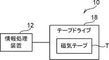
- the information processing system 10 includes an information processing device 12 and a tape drive 18 .
- the information processing device 12 include a server computer and the like.
- a magnetic tape T as an example of a recording medium is stored in the tape drive 18 .
- a tape drive 18 is connected to the information processing device 12 .
- the tape drive 18 has a control device (not shown) including a processor, and writes data to or reads data from the magnetic tape T under the control of the information processing device 12 .
- An example of the magnetic tape T is an LTO (Linear Tape-Open) tape.
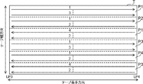
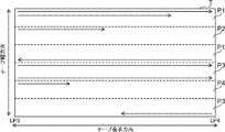
- the magnetic tape T is divided into a plurality of partial areas P1 to P4 along straight lines along the longitudinal direction of the magnetic tape T in which user data is recorded.
- the area in which user data is recorded is, for example, the area from LP (Logical Point) 3 to LP4 on the LTO tape.
- the partial areas P1 to P4 are collectively referred to as "partial area P".
- the partial area P corresponds to, for example, a partition obtained by dividing the area in which the user data of the magnetic tape T is recorded by the partition function defined by the LTO standard. Areas with the same number at the end of the code of the partial area P indicate the same partition. That is, FIG. 2 shows an example in which the magnetic tape T has four partitions. 2 represents the direction of data recording, that is, the direction of movement of the magnetic head relative to the magnetic tape T. As shown in FIG. Also, the numbers written above the solid line arrows in FIG. The number of partial regions P is not limited to the example in FIG. 2, and may be two, three, or five or more.
- the information processing device 12 includes a CPU (Central Processing Unit) 20, a memory 21 as a temporary storage area, and a non-volatile storage section 22.
- FIG. The information processing device 12 also includes a display 23 such as a liquid crystal display, an input device 24 such as a keyboard and a mouse, a network I/F (Interface) 25 connected to a network, and an external I/F 26 to which a tape drive 18 is connected.
- CPU 20 , memory 21 , storage unit 22 , display 23 , input device 24 , network I/F 25 and external I/F 26 are connected to bus 27 .
- the storage unit 22 is implemented by a HDD (Hard Disk Drive), SSD (Solid State Drive), flash memory, or the like.
- An information processing program 30 is stored in the storage unit 22 as a storage medium.
- the CPU 20 reads out the information processing program 30 from the storage unit 22 , expands it in the memory 21 , and executes the expanded information processing program 30 .
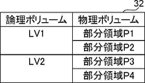
- the storage unit 22 also stores a volume management table 32 for associating logical volumes with physical volumes.
- An example of the volume management table 32 is shown in FIG.
- the volume management table 32 associates logical volumes with physical volumes.
- a logical volume is a logical storage area that is designated when data is recorded.
- a physical volume is a storage area in which data is physically recorded, and is partial areas P1 to P4 in this embodiment.
- FIG. 4 shows an example in which two partial areas P are associated with two logical volumes, the present invention is not limited to this. For example, four partial areas P may be associated with one logical volume.
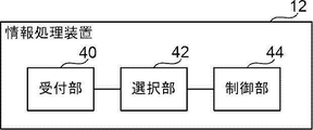
- the information processing device 12 includes a reception section 40 , a selection section 42 and a control section 44 .
- the CPU 20 functions as a reception unit 40 , a selection unit 42 and a control unit 44 .
- the reception unit 40 receives data to be recorded and an instruction to record on the magnetic tape T transmitted from the user terminal.
- the selection unit 42 selects the partial area P that minimizes the seek cost of the magnetic head from among the plurality of partial areas P associated with the logical volume of the data recording destination received by the receiving unit 40 .
- the seek distance is used as the seek cost of the magnetic head, and the shorter the seek distance, the smaller the seek cost.
- the selection unit 42 selects the partial area P in which the seek distance of the magnetic head is the shortest. Seeking here means moving the magnetic head from a stop position to a position where writing is started.
- the method of specifying the logical volume as the recording destination of the data to be recorded is not particularly limited.
- a user operating a user terminal may designate a logical volume as a data recording destination.
- the selection unit 42 may select the logical volume of the data recording destination based on the data received by the reception unit 40 .
- the selection unit 42 selects a logical volume according to the type of data such as image data and document data.
- the selection unit 42 selects a logical volume according to the period during which data such as January data and February data was acquired.
- FIG. 6 shows the data recording state immediately before the selection unit 42 selects the partial area P.
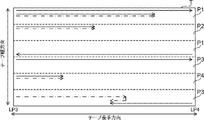
- FIG. 7 additionally shows the seek path of the magnetic head when data is additionally written in each partial area P in FIG.
- the solid arrows in FIGS. 6 and 7 represent the data recorded in each partial area P.
- the dashed-dotted arrows in FIG. 7 represent the seek paths of the magnetic head when data is additionally written in each partial area P.
- the dashed-dotted line arrows are slightly shifted from the solid line arrows. It is also assumed here that the stop position of the magnetic head is on the leading side (left side in FIGS. 6 and 7) of LP3 of the magnetic tape.
- the selection unit 42 selects the partial area P4.
- the selection unit 42 selects one partial area P from the plurality of partial areas P according to a preset rule. good too.
- Rules in this case include, for example, a rule of random selection, a rule of selecting the partial area P with the smallest assigned number, or a rule of selecting the partial area P with the largest free space. .
- the control unit 44 performs control to record the data received by the receiving unit 40 in the partial area P selected by the selecting unit 42 .
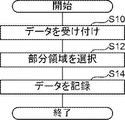
- the data recording process shown in FIG. 8 is executed by the CPU 20 executing the information processing program 30 .
- the data recording process shown in FIG. 8 is executed, for example, when the information processing apparatus 12 receives data to be recorded and an instruction to record on the magnetic tape T transmitted from the user terminal.
- the reception unit 40 receives the data to be recorded and the instruction to record on the magnetic tape T transmitted from the user terminal.
- the selection unit 42 selects the portion of the plurality of partial areas P associated with the logical volume as the recording destination of the data received in step S10, where the seek cost of the magnetic head is the minimum. Select region P.
- step S14 the control unit 44 performs control to record the data received in step S10 in the partial area P selected in step S12.
- the data recording process ends.
- the seek cost of the magnetic head can be reduced.
- the selection unit 42 reselects the partial area P whose free space is equal to or greater than the size of the data to be recorded. good too. In this case, for example, the selection unit 42 selects the partial area P with the lowest seek cost from among the partial areas P whose free space is equal to or greater than the size of the data to be recorded.
- the selection unit 42 selects the partial area P with the shortest seek distance of the magnetic head as the partial area P with the minimum seek cost of the magnetic head.
- the seek distance of the magnetic head is accompanied by a band change
- the seek distance is considered to be the shortest.
- the selection unit 42 may select the partial area P that minimizes the seek time of the magnetic head as the partial area P that minimizes the seek cost of the magnetic head.
- the functions of the reception unit 40, the selection unit 42, and the control unit 44 implemented by the CPU 20 may be implemented by a processor included in the control device of the tape drive 18.
- the hardware structure of the processing unit (processing unit) that executes various processes includes the following various processors ( processor) can be used.
- the various processors include, in addition to the CPU, which is a general-purpose processor that executes software (programs) and functions as various processing units, circuits such as FPGAs (Field Programmable Gate Arrays), etc.
- Programmable Logic Device (PLD) which is a processor whose configuration can be changed, ASIC (Application Specific Integrated Circuit) etc. Circuits, etc. are included.
- One processing unit may be composed of one of these various processors, or a combination of two or more processors of the same type or different types (for example, a combination of multiple FPGAs, a combination of a CPU and an FPGA). combination). Also, a plurality of processing units may be configured by one processor.
- a single processor is configured by combining one or more CPUs and software.
- a processor functions as multiple processing units.
- SoC System on Chip
- the various processing units are configured using one or more of the above various processors as a hardware structure.
- an electric circuit combining circuit elements such as semiconductor elements can be used.
- the information processing program 30 has been pre-stored (installed) in the storage unit 22, but the present invention is not limited to this.
- the information processing program 30 is provided in a form recorded on a recording medium such as a CD-ROM (Compact Disc Read Only Memory), a DVD-ROM (Digital Versatile Disc Read Only Memory), and a USB (Universal Serial Bus) memory. good too. Further, the information processing program 30 may be downloaded from an external device via a network.
Landscapes
- Engineering & Computer Science (AREA)
- Databases & Information Systems (AREA)
- Theoretical Computer Science (AREA)
- Signal Processing (AREA)
- Data Mining & Analysis (AREA)
- Physics & Mathematics (AREA)
- General Engineering & Computer Science (AREA)
- General Physics & Mathematics (AREA)
- Signal Processing For Digital Recording And Reproducing (AREA)
Abstract
情報処理装置は、磁気テープが分割された複数の部分領域のうち、磁気ヘッドのシークコストが最小となる部分領域を選択し、選択した部分領域にデータを記録する制御を行う。
Description
本開示は、情報処理装置、情報処理方法、及び情報処理プログラムに関する。
特開2016-110669号公報には、複数のファイルそれぞれを所定サイズで分割したセグメントのうち、各ファイルの先頭セグメントを磁気ヘッドのシーク距離が短くなる位置に記録する技術が開示されている。
特開2013-206518号公報には、データパーティションに記録されたデータをキャッシュパーティションにコピーする際に、平均アクセス距離が最短となる位置にデータをコピーする技術が開示されている。
ところで、近年の磁気テープは、複数のパーティションに領域を分割することが可能となっている。このような磁気テープに新たなデータを追記する場合、磁気ヘッドのシークコストを低減することができることが好ましい。
しかしながら、特開2016-110669号公報に記載の技術は、磁気テープの複数のパーティションにデータを記録することについては考慮されていない。また、特開2013-206518号公報に記載の技術は、磁気テープ内でデータをコピーするものであり、新たなデータを追記することについては考慮されていない。
本開示は、以上の事情を鑑みてなされたものであり、磁気ヘッドのシークコストを低減することができる情報処理装置、情報処理方法、及び情報処理プログラムを提供することを目的とする。
本開示の情報処理装置は、少なくとも一つのプロセッサを備える情報処理装置であって、プロセッサは、磁気テープが分割された複数の部分領域のうち、磁気ヘッドのシークコストが最小となる部分領域を選択し、選択した部分領域にデータを記録する制御を行う。
なお、本開示の情報処理装置は、磁気ヘッドのシークコストが最小とは、磁気ヘッドのシーク距離が最短のことであってもよい。
また、本開示の情報処理装置は、磁気ヘッドのシークコストが最小とは、磁気ヘッドのシーク時間が最短のことであってもよい。
また、本開示の情報処理装置は、プロセッサが、選択した部分領域の空き容量が記録対象のデータのサイズ未満の場合、空き容量が記録対象のデータのサイズ以上の部分領域を再度選択してもよい。
また、本開示の情報処理装置は、複数の部分領域が、1つの論理ボリュームに対応付けられ、プロセッサが、記録対象のデータの記録先の論理ボリュームに対応付けられた複数の部分領域のうち、磁気ヘッドのシークコストが最小となる部分領域を選択してもよい。
また、本開示の情報処理方法は、磁気テープが分割された複数の部分領域のうち、磁気ヘッドのシークコストが最小となる部分領域を選択し、選択した部分領域にデータを記録する制御を行う処理を情報処理装置が備えるプロセッサが実行するものである。
また、本開示の情報処理プログラムは、磁気テープが分割された複数の部分領域のうち、磁気ヘッドのシークコストが最小となる部分領域を選択し、選択した部分領域にデータを記録する制御を行う処理を情報処理装置が備えるプロセッサに実行させるためのものである。
本開示によれば、磁気ヘッドのシークコストを低減することができる。
以下、図面を参照して、本開示の技術を実施するための形態例を詳細に説明する。
まず、図1を参照して、本実施形態に係る情報処理システム10の構成を説明する。図1に示すように、情報処理システム10は、情報処理装置12及びテープドライブ18を含む。情報処理装置12の例としては、サーバコンピュータ等が挙げられる。
テープドライブ18には、記録媒体の一例としての磁気テープTが格納される。テープドライブ18は、情報処理装置12に接続される。テープドライブ18は、プロセッサを含む制御装置(図示省略)を備え、情報処理装置12による制御によって、磁気テープTに対するデータの書き込み又は読み取りを行う。磁気テープTの例としては、LTO(Linear Tape-Open)テープが挙げられる。
次に、図2を参照して、本実施形態に係る磁気テープTの構成を説明する。図2に示すように、磁気テープTは、ユーザデータが記録される領域が磁気テープTの長手方向に沿った直線で複数の部分領域P1~P4に分割される。ユーザデータが記録される領域とは、例えば、LTOテープにおけるLP(Logical Point)3からLP4までの領域である。以下では、部分領域P1~P4を総称する場合は「部分領域P」という。
部分領域Pは、例えば、LTO規格で規定されたパーティション機能により磁気テープTのユーザデータが記録される領域が分割されたパーティションに相当する。部分領域Pの符号の末尾の数字が同じ領域は、同じパーティションであることを示している。すなわち、図2では、磁気テープTが4つのパーティションを備える例を示している。また、図2における実線の矢印は、データの記録方向、すなわち、磁気ヘッドの磁気テープTに対する相対的な移動方向を表している。また、図2における実線の矢印の上に記載されている数字は各部分領域P内でのデータの記録順を表している。なお、部分領域Pの数は、図2の例に限定されず、2つでもよいし、3つでもよいし、5つ以上でもよい。
次に、図3を参照して、本実施形態に係る情報処理装置12のハードウェア構成を説明する。図3に示すように、情報処理装置12は、CPU(Central Processing Unit)20、一時記憶領域としてのメモリ21、及び不揮発性の記憶部22を含む。また、情報処理装置12は、液晶ディスプレイ等のディスプレイ23、キーボードとマウス等の入力装置24、ネットワークに接続されるネットワークI/F(InterFace)25、及びテープドライブ18が接続される外部I/F26を含む。CPU20、メモリ21、記憶部22、ディスプレイ23、入力装置24、ネットワークI/F25、及び外部I/F26は、バス27に接続される。
記憶部22は、HDD(Hard Disk Drive)、SSD(Solid State Drive)、又はフラッシュメモリ等によって実現される。記憶媒体としての記憶部22には、情報処理プログラム30が記憶される。CPU20は、記憶部22から情報処理プログラム30を読み出してからメモリ21に展開し、展開した情報処理プログラム30を実行する。
また、記憶部22には、論理ボリュームと物理ボリュームとを対応付けるためのボリューム管理テーブル32が記憶される。図4にボリューム管理テーブル32の一例を示す。図4に示すように、ボリューム管理テーブル32では、論理ボリュームと物理ボリュームとが対応付けられる。論理ボリュームは、データを記録するときに指定する論理的な記憶領域である。物理ボリュームは、データが物理的に記録される記憶領域であり、本実施形態では、部分領域P1~P4である。図4では、2つの論理ボリュームに、それぞれ2つの部分領域Pが対応付けられる例を示しているが、これに限定されない。たとえば、1つの論理ボリュームに4つの部分領域Pが対応付けられてもよい。
次に、図5を参照して、本実施形態に係る情報処理装置12の機能的な構成について説明する。図5に示すように、情報処理装置12は、受付部40、選択部42、及び制御部44を含む。CPU20が情報処理プログラム30を実行することにより、受付部40、選択部42、及び制御部44として機能する。
受付部40は、ユーザ端末から送信された記録対象のデータと磁気テープTへの記録指示とを受け付ける。
選択部42は、受付部40により受け付けられたデータの記録先の論理ボリュームに対応付けられた複数の部分領域Pのうち、磁気ヘッドのシークコストが最小となる部分領域Pを選択する。本実施形態では、磁気ヘッドのシークコストとしてシーク距離を適用し、シーク距離が短いほどシークコストが小さいものとする。すなわち、選択部42は、磁気ヘッドのシーク距離が最短となる部分領域Pを選択する。ここでいうシークとは、磁気ヘッドが停止位置から書き込みを開始する位置まで移動することを意味する。
なお、記録対象のデータの記録先の論理ボリュームの指定方法は特に限定されない。例えば、ユーザ端末を操作するユーザによってデータの記録先の論理ボリュームが指定されてもよい。また、例えば、選択部42が、受付部40により受け付けられたデータに基づいて、データの記録先の論理ボリュームを選択してもよい。この場合、例えば、選択部42は、画像データ及び文書データ等のデータの種別に応じて論理ボリュームを選択する。また、この場合、例えば、選択部42は、1月のデータ及び2月のデータ等のデータが取得された期間に応じて論理ボリュームを選択する。
図6及び図7を参照して、選択部42による部分領域Pの選択処理の具体例を説明する。ここでは、説明を分かりやすくするために、データの記録先の1つの論理ボリュームに4つの部分領域Pが対応付けられているものとする。図6は、選択部42が部分領域Pを選択する直前のデータの記録状態を示している。図7は、図6に対して、各部分領域Pにデータを追記する場合における磁気ヘッドのシーク経路を追記したものである。
図6及び図7における実線の矢印は、各部分領域Pに記録済みのデータを表している。また、図7における一点鎖線の矢印は、各部分領域Pにデータを追記する場合における磁気ヘッドのシーク経路を表している。但し、図を見やすくするために、一点鎖線の矢印は実線の矢印と若干ずらしている。また、ここでは、磁気ヘッドの停止位置は、磁気テープのLP3よりも先頭側(図6及び図7の左側)であるものとする。
図7に示すように、この例では、部分領域P1~P4のうち部分領域P4をデータの記録先とした場合に、磁気ヘッドのシーク距離が最短となる。そこで、図7の例では、選択部42は、部分領域P4を選択する。
なお、選択部42は、磁気ヘッドのシークコストが最小となる部分領域Pが複数ある場合は、予め設定されたルールに従って、その複数の部分領域Pの中から1つの部分領域Pを選択してもよい。この場合のルールとしては、例えば、ランダムに選択するというルール、割り当てられた番号が最小の部分領域Pを選択するというルール、又は空き容量が最大の部分領域Pを選択するというルール等が挙げられる。
制御部44は、受付部40により受け付けられたデータを選択部42により選択された部分領域Pに記録する制御を行う。
次に、図8を参照して、本実施形態に係る情報処理装置12の作用を説明する。CPU20が情報処理プログラム30を実行することによって、図8に示すデータ記録処理が実行される。図8に示すデータ記録処理は、例えば、ユーザ端末から送信された記録対象のデータと磁気テープTへの記録指示とを情報処理装置12が受信した場合に実行される。
図8のステップS10で、受付部40は、ユーザ端末から送信された記録対象のデータと磁気テープTへの記録指示とを受け付ける。ステップS12で、選択部42は、前述したように、ステップS10で受け付けられたデータの記録先の論理ボリュームに対応付けられた複数の部分領域Pのうち、磁気ヘッドのシークコストが最小となる部分領域Pを選択する。
ステップS14で、制御部44は、ステップS10で受け付けられたデータをステップS12で選択された部分領域Pに記録する制御を行う。ステップS14の処理が終了すると、データ記録処理が終了する。
以上説明したように、本実施形態によれば、磁気ヘッドのシークコストを低減することができる。
なお、上記実施形態において、選択部42は、選択した部分領域Pの空き容量が記録対象のデータのサイズ未満の場合、空き容量が記録対象のデータのサイズ以上の部分領域Pを再度選択してもよい。この場合、例えば、選択部42は、空き容量が記録対象のデータのサイズ以上の部分領域Pのうち、シークコストが最小の部分領域Pを選択する。
また、上記実施形態では、選択部42が、磁気ヘッドのシークコストが最小となる部分領域Pとして、磁気ヘッドのシーク距離が最短となる部分領域Pを選択する場合について説明したが、これに限定されない。例えば、磁気ヘッドのシークの際にバンドチェンジを伴う場合、磁気テープTの走行方向の反転が求められる場合、又はシーク距離が近すぎるが故にラップチェンジするゆとりがない場合等、シーク距離が最短となる場合が、必ずしもシーク時間が最短となるとは限らない。このような場合、選択部42は、磁気ヘッドのシークコストが最小となる部分領域Pとして、磁気ヘッドのシーク時間が最短となる部分領域Pを選択してもよい。
また、上記実施形態において、CPU20により実現される受付部40、選択部42、及び制御部44の機能をテープドライブ18の制御装置が備えるプロセッサにより実現してもよい。
また、上記実施形態において、例えば、受付部40、選択部42、及び制御部44といった各種の処理を実行する処理部(processing unit)のハードウェア的な構造としては、次に示す各種のプロセッサ(processor)を用いることができる。上記各種のプロセッサには、前述したように、ソフトウェア(プログラム)を実行して各種の処理部として機能する汎用的なプロセッサであるCPUに加えて、FPGA(Field Programmable Gate Array)等の製造後に回路構成を変更可能なプロセッサであるプログラマブルロジックデバイス(Programmable Logic Device:PLD)、ASIC(Application Specific Integrated Circuit)等の特定の処理を実行させるために専用に設計された回路構成を有するプロセッサである専用電気回路等が含まれる。
1つの処理部は、これらの各種のプロセッサのうちの1つで構成されてもよいし、同種又は異種の2つ以上のプロセッサの組み合わせ(例えば、複数のFPGAの組み合わせや、CPUとFPGAとの組み合わせ)で構成されてもよい。また、複数の処理部を1つのプロセッサで構成してもよい。
複数の処理部を1つのプロセッサで構成する例としては、第1に、クライアント及びサーバ等のコンピュータに代表されるように、1つ以上のCPUとソフトウェアの組み合わせで1つのプロセッサを構成し、このプロセッサが複数の処理部として機能する形態がある。第2に、システムオンチップ(System on Chip:SoC)等に代表されるように、複数の処理部を含むシステム全体の機能を1つのIC(Integrated Circuit)チップで実現するプロセッサを使用する形態がある。このように、各種の処理部は、ハードウェア的な構造として、上記各種のプロセッサの1つ以上を用いて構成される。
更に、これらの各種のプロセッサのハードウェア的な構造としては、より具体的には、半導体素子などの回路素子を組み合わせた電気回路(circuitry)を用いることができる。
また、上記実施形態では、情報処理プログラム30が記憶部22に予め記憶(インストール)されている態様を説明したが、これに限定されない。情報処理プログラム30は、CD-ROM(Compact Disc Read Only Memory)、DVD-ROM(Digital Versatile Disc Read Only Memory)、及びUSB(Universal Serial Bus)メモリ等の記録媒体に記録された形態で提供されてもよい。また、情報処理プログラム30は、ネットワークを介して外部装置からダウンロードされる形態としてもよい。
2021年3月18日に出願された日本国特許出願2021-044957号の開示は、その全体が参照により本明細書に取り込まれる。また、本明細書に記載された全ての文献、特許出願、及び技術規格は、個々の文献、特許出願、及び技術規格が参照により取り込まれることが具体的かつ個々に記された場合と同程度に、本明細書中に参照により取り込まれる。
Claims (7)
- 少なくとも一つのプロセッサを備える情報処理装置であって、
前記プロセッサは、
磁気テープが分割された複数の部分領域のうち、磁気ヘッドのシークコストが最小となる部分領域を選択し、
選択した部分領域にデータを記録する制御を行う
情報処理装置。 - 磁気ヘッドのシークコストが最小とは、磁気ヘッドのシーク距離が最短のことである
請求項1に記載の情報処理装置。 - 磁気ヘッドのシークコストが最小とは、磁気ヘッドのシーク時間が最短のことである
請求項1に記載の情報処理装置。 - 前記プロセッサは、
選択した部分領域の空き容量が記録対象のデータのサイズ未満の場合、空き容量が前記記録対象のデータのサイズ以上の部分領域を再度選択する
請求項1から請求項3の何れか1項に記載の情報処理装置。 - 複数の部分領域は、1つの論理ボリュームに対応付けられ、
前記プロセッサは、
記録対象のデータの記録先の論理ボリュームに対応付けられた複数の部分領域のうち、磁気ヘッドのシークコストが最小となる部分領域を選択する
請求項1から請求項4の何れか1項に記載の情報処理装置。 - 磁気テープが分割された複数の部分領域のうち、磁気ヘッドのシークコストが最小となる部分領域を選択し、
選択した部分領域にデータを記録する制御を行う
処理を情報処理装置が備えるプロセッサが実行する情報処理方法。 - 磁気テープが分割された複数の部分領域のうち、磁気ヘッドのシークコストが最小となる部分領域を選択し、
選択した部分領域にデータを記録する制御を行う
処理を情報処理装置が備えるプロセッサに実行させるための情報処理プログラム。
Priority Applications (1)
| Application Number | Priority Date | Filing Date | Title |
|---|---|---|---|
| JP2023506750A JPWO2022195984A1 (ja) | 2021-03-18 | 2021-12-10 |
Applications Claiming Priority (2)
| Application Number | Priority Date | Filing Date | Title |
|---|---|---|---|
| JP2021-044957 | 2021-03-18 | ||
| JP2021044957 | 2021-03-18 |
Publications (1)
| Publication Number | Publication Date |
|---|---|
| WO2022195984A1 true WO2022195984A1 (ja) | 2022-09-22 |
Family
ID=83320011
Family Applications (1)
| Application Number | Title | Priority Date | Filing Date |
|---|---|---|---|
| PCT/JP2021/045634 WO2022195984A1 (ja) | 2021-03-18 | 2021-12-10 | 情報処理装置、情報処理方法、及び情報処理プログラム |
Country Status (2)
| Country | Link |
|---|---|
| JP (1) | JPWO2022195984A1 (ja) |
| WO (1) | WO2022195984A1 (ja) |
Citations (3)
| Publication number | Priority date | Publication date | Assignee | Title |
|---|---|---|---|---|
| JP2010152603A (ja) * | 2008-12-25 | 2010-07-08 | Internatl Business Mach Corp <Ibm> | 記録媒体に記録されたデータの移行のための装置及び方法 |
| JP2014507744A (ja) * | 2011-01-31 | 2014-03-27 | オラクル・インターナショナル・コーポレイション | 記憶媒体のホスト設定を用いてデータを記憶するためのシステムおよび方法 |
| JP2017204314A (ja) * | 2016-05-11 | 2017-11-16 | 富士通株式会社 | テープ装置、制御装置および制御プログラム |
-
2021
- 2021-12-10 JP JP2023506750A patent/JPWO2022195984A1/ja active Pending
- 2021-12-10 WO PCT/JP2021/045634 patent/WO2022195984A1/ja active Application Filing
Patent Citations (3)
| Publication number | Priority date | Publication date | Assignee | Title |
|---|---|---|---|---|
| JP2010152603A (ja) * | 2008-12-25 | 2010-07-08 | Internatl Business Mach Corp <Ibm> | 記録媒体に記録されたデータの移行のための装置及び方法 |
| JP2014507744A (ja) * | 2011-01-31 | 2014-03-27 | オラクル・インターナショナル・コーポレイション | 記憶媒体のホスト設定を用いてデータを記憶するためのシステムおよび方法 |
| JP2017204314A (ja) * | 2016-05-11 | 2017-11-16 | 富士通株式会社 | テープ装置、制御装置および制御プログラム |
Also Published As
| Publication number | Publication date |
|---|---|
| JPWO2022195984A1 (ja) | 2022-09-22 |
Similar Documents
| Publication | Publication Date | Title |
|---|---|---|
| US11456015B2 (en) | Derivation device, derivation method, derivation program, and magnetic tape | |
| WO2021171814A1 (ja) | 情報処理装置、情報処理方法、及び情報処理プログラム | |
| WO2021171683A1 (ja) | 情報処理装置、情報処理方法、及び情報処理プログラム | |
| WO2022195984A1 (ja) | 情報処理装置、情報処理方法、及び情報処理プログラム | |
| JP7167192B2 (ja) | 記録装置、記録方法、記録プログラム、及び磁気テープ | |
| WO2022163078A1 (ja) | 情報処理装置、情報処理方法、及び情報処理プログラム | |
| US20230065229A1 (en) | Information processing apparatus, information processing method, and information processing program | |
| WO2022172548A1 (ja) | 情報処理装置、情報処理方法、及び情報処理プログラム | |
| WO2021177246A1 (ja) | 情報処理装置、情報処理方法、及び情報処理プログラム | |
| WO2022168405A1 (ja) | 情報処理装置、情報処理方法、及び情報処理プログラム | |
| WO2022195983A1 (ja) | 情報処理装置、情報処理方法、及び情報処理プログラム | |
| WO2022176345A1 (ja) | 情報処理装置、情報処理方法、及び情報処理プログラム | |
| WO2022176344A1 (ja) | 情報処理装置、情報処理方法、及び情報処理プログラム | |
| JP2023032334A (ja) | 情報処理装置、情報処理方法、及び情報処理プログラム | |
| JP2023111328A (ja) | 情報処理装置、情報処理方法、及び情報処理プログラム | |
| WO2022044433A1 (ja) | 情報処理装置、情報処理方法、及び情報処理プログラム | |
| JP2023068982A (ja) | 情報処理装置、情報処理方法、及び情報処理プログラム | |
| WO2022172549A1 (ja) | 情報処理装置、情報処理方法、及び情報処理プログラム | |
| US20230047128A1 (en) | Information processing apparatus, information processing method, and information processing program | |
| WO2022049832A1 (ja) | 情報処理装置、情報処理方法、及び情報処理プログラム | |
| WO2022044434A1 (ja) | 情報処理装置、情報処理方法、及び情報処理プログラム | |
| EP4134803A1 (en) | Information processing apparatus, information processing method, and information processing program | |
| WO2021171816A1 (ja) | 情報処理装置、情報処理方法、及び情報処理プログラム | |
| WO2021186774A1 (ja) | 情報処理装置、情報処理方法、及び情報処理プログラム | |
| JP2024037470A (ja) | 情報処理装置、情報処理方法、及び情報処理プログラム |
Legal Events
| Date | Code | Title | Description |
|---|---|---|---|
| 121 | Ep: the epo has been informed by wipo that ep was designated in this application |
Ref document number: 21931726 Country of ref document: EP Kind code of ref document: A1 |
|
| WWE | Wipo information: entry into national phase |
Ref document number: 2023506750 Country of ref document: JP |
|
| NENP | Non-entry into the national phase |
Ref country code: DE |
|
| 122 | Ep: pct application non-entry in european phase |
Ref document number: 21931726 Country of ref document: EP Kind code of ref document: A1 |