WO2022195709A1 - 発電ユニット及びシリーズハイブリッド車両 - Google Patents
発電ユニット及びシリーズハイブリッド車両 Download PDFInfo
- Publication number
- WO2022195709A1 WO2022195709A1 PCT/JP2021/010578 JP2021010578W WO2022195709A1 WO 2022195709 A1 WO2022195709 A1 WO 2022195709A1 JP 2021010578 W JP2021010578 W JP 2021010578W WO 2022195709 A1 WO2022195709 A1 WO 2022195709A1
- Authority
- WO
- WIPO (PCT)
- Prior art keywords
- engine
- power generation
- generator
- generation unit
- axial gap
- Prior art date
- Legal status (The legal status is an assumption and is not a legal conclusion. Google has not performed a legal analysis and makes no representation as to the accuracy of the status listed.)
- Ceased
Links
Images




Classifications
-
- B—PERFORMING OPERATIONS; TRANSPORTING
- B60—VEHICLES IN GENERAL
- B60K—ARRANGEMENT OR MOUNTING OF PROPULSION UNITS OR OF TRANSMISSIONS IN VEHICLES; ARRANGEMENT OR MOUNTING OF PLURAL DIVERSE PRIME-MOVERS IN VEHICLES; AUXILIARY DRIVES FOR VEHICLES; INSTRUMENTATION OR DASHBOARDS FOR VEHICLES; ARRANGEMENTS IN CONNECTION WITH COOLING, AIR INTAKE, GAS EXHAUST OR FUEL SUPPLY OF PROPULSION UNITS IN VEHICLES
- B60K6/00—Arrangement or mounting of plural diverse prime-movers for mutual or common propulsion, e.g. hybrid propulsion systems comprising electric motors and internal combustion engines
- B60K6/20—Arrangement or mounting of plural diverse prime-movers for mutual or common propulsion, e.g. hybrid propulsion systems comprising electric motors and internal combustion engines the prime-movers consisting of electric motors and internal combustion engines, e.g. HEVs
- B60K6/42—Arrangement or mounting of plural diverse prime-movers for mutual or common propulsion, e.g. hybrid propulsion systems comprising electric motors and internal combustion engines the prime-movers consisting of electric motors and internal combustion engines, e.g. HEVs characterised by the architecture of the hybrid electric vehicle
- B60K6/46—Series type
-
- B—PERFORMING OPERATIONS; TRANSPORTING
- B60—VEHICLES IN GENERAL
- B60L—PROPULSION OF ELECTRICALLY-PROPELLED VEHICLES; SUPPLYING ELECTRIC POWER FOR AUXILIARY EQUIPMENT OF ELECTRICALLY-PROPELLED VEHICLES; ELECTRODYNAMIC BRAKE SYSTEMS FOR VEHICLES IN GENERAL; MAGNETIC SUSPENSION OR LEVITATION FOR VEHICLES; MONITORING OPERATING VARIABLES OF ELECTRICALLY-PROPELLED VEHICLES; ELECTRIC SAFETY DEVICES FOR ELECTRICALLY-PROPELLED VEHICLES
- B60L50/00—Electric propulsion with power supplied within the vehicle
- B60L50/50—Electric propulsion with power supplied within the vehicle using propulsion power supplied by batteries or fuel cells
- B60L50/60—Electric propulsion with power supplied within the vehicle using propulsion power supplied by batteries or fuel cells using power supplied by batteries
- B60L50/61—Electric propulsion with power supplied within the vehicle using propulsion power supplied by batteries or fuel cells using power supplied by batteries by batteries charged by engine-driven generators, e.g. series hybrid electric vehicles
-
- B—PERFORMING OPERATIONS; TRANSPORTING
- B60—VEHICLES IN GENERAL
- B60Y—INDEXING SCHEME RELATING TO ASPECTS CROSS-CUTTING VEHICLE TECHNOLOGY
- B60Y2200/00—Type of vehicle
- B60Y2200/90—Vehicles comprising electric prime movers
- B60Y2200/92—Hybrid vehicles
Definitions
- This disclosure relates to power generation units and series hybrid vehicles.
- Patent Document 1 discloses a series hybrid vehicle that includes an electric motor for running that is driven by electric power from a battery, and an engine for power generation that drives a generator and charges the battery.
- the engine and generator are integrated with each other to form a power generation unit.
- the engine is arranged with the crankshaft oriented vertically, and the generator is arranged below the engine.
- the present disclosure aims to make the entire power generation unit compact without degrading the power generation performance.
- a power generation unit includes an engine having a crankshaft whose axial direction extends vertically, a rotor rotatably connected to the crankshaft around a rotation axis extending in the axial direction, and the rotor and a stator facing the rotor in the axial direction with a gap in the axial direction from the stator, and an axial gap generator disposed on one side of the engine in the axial direction.
- the generator is arranged on one side in the vertical direction of the engine arranged so that the crankshaft extends in the vertical direction, the space occupied by the power generation unit in the horizontal direction is reduced. Since the generator is of the axial gap type and the rotor is arranged to rotate about a vertically extending rotation axis, the vertical occupied space of the power generation unit is also reduced. Therefore, the entire power generation unit can be made compact without lowering the power generation performance.
- a series hybrid vehicle includes a power generation unit, a battery that can be charged with power generated by the power generation unit, an electric motor that is driven by the power from the battery and generates driving power, and at least It comprises one wheel and a vehicle body supported by the wheel.
- the power generation unit includes an engine having a vertically extending crankshaft, a rotor rotatably connected to the crankshaft about a rotation axis extending in the axial direction of the crankshaft, and a rotor rotating in the axial direction from the rotor. a stator facing the rotor in the axial direction with a gap therebetween, and an axial gap generator arranged on one side in the vertical direction of the engine.
- the power generation unit is mounted on the vehicle body such that the lower end of the axial gap generator is positioned lower than the upper end of the wheel.
- the entire power generation unit can be made compact without deteriorating power generation performance.
- FIG. 1 is a plan view of a power generation unit according to an embodiment.
- FIG. FIG. 2 is a cross-sectional view of the power generation unit of FIG. 1 taken along the line II-II.
- FIG. 3 is a block diagram of a hybrid vehicle in which the power generation unit of FIG. 2 is detachably mounted.
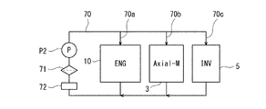
- 4 is a block diagram of the cooling structure of the power generation unit of FIG. 2.
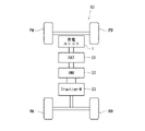
- FIG. 5 is a schematic diagram of the hybrid vehicle of FIG. 6 is a side view of the hybrid vehicle of FIG. 5.
- FIG. FIG. 7 is a schematic cross-sectional view of the power generation unit of the hybrid vehicle of FIG. 6 and its vicinity as viewed from the front. 8 is a block diagram of a first modification of the power generation unit of FIG. 3.
- FIG. 9 is a block diagram of a second modification of the power generation unit of FIG. 3.
- FIG. 10 is a side view of a modification of the hybrid vehicle in which the power generation unit of FIG. 2 is detachably mounted.
- the power generation unit 1 described below has a crankshaft 22 extending in the vertical direction (vertical direction).
- the vertical direction of the power generation unit 1 is the direction in which the crankshaft 22 extends
- the in-plane direction orthogonal to the crankshaft 22 is the horizontal direction of the power generation unit 1 .
- FIG. 1 is a plan view of the power generation unit 1 according to the embodiment.
- FIG. 2 is a cross-sectional view of the power generation unit 1 of FIG. 1 taken along the line II-II.
- the power generation unit 1 includes an engine unit 2 and an axial gap power generator 3 driven by the engine unit 2 .
- the engine unit 2 includes an engine 10 which is an internal combustion engine, and an upper cover 11 provided on the upper side of the engine 10 .
- the engine 10 of the engine unit 2 is a multi-cylinder engine, such as a V-twin engine.
- the engine 10 includes a crankcase 21 , a crankshaft 22 , a pair of cylinders 23 and a valve train 24 .
- the crankshaft 22 is housed in the crankcase 21 while being rotatably supported by the crankcase 21 .
- a rotation axis X of the crankshaft 22 extends vertically.
- the crankshaft 22 rotates in conjunction with the reciprocating motion of the pistons in the cylinders 23 .
- the crankshaft gives kinetic energy to the connection object by rotating the connection object.
- the cylinder 23 extends horizontally when viewed from the crankshaft 22 .
- the upper cover 11 of the engine unit 2 is fixed to the crankcase 21 so as to cover the crankcase 21 from above.
- the upper cover 11 has an inverted concave cross-sectional shape that opens downward.
- Upper cover 11 defines an internal space with crankcase 21 .
- An upper portion of a crankshaft 22 protruding upward from a crankcase 21 is arranged in the internal space of the upper cover 11 .
- a cooling fan 12 and a sub-generator 14 are arranged in the inner space of the upper cover 11 above the engine 10 .
- the sub-generator 14 is attached to the upper part of the crankshaft 22. That is, the sub-generator 14 generates power by rotating its rotor (not shown) in conjunction with the crankshaft 22 .
- the electric power generated by the sub-generator 14 is used as electric power necessary for driving the engine 10 .
- the electric power generated by the sub-generator 14 is supplied to the electronic control unit 4 and the like, which will be described later.
- a cooling fan 12 is attached to the upper part of the crankshaft 22 above the sub-generator 14 .
- An inlet 11 a is formed in the upper plate portion of the upper cover 11 .
- a fan cover 13 is detachably attached to the upper cover 11 so as to cover the inlet 11a.
- the fan cover 13 has, for example, a mesh structure that allows air to pass while preventing foreign matter from passing.
- a side plate portion of the upper cover 11 is formed with an outflow port 11b.
- a louver may be provided at the outflow port 11b.
- the valve train 24 has a camshaft 24a extending in the vertical direction, and mechanically interlocks with the crankshaft 22 to open and close intake and exhaust valves (not shown) of the cylinder 23.
- the configuration of the valve train 24 is a known one, and the configuration is not particularly limited. Rotation of the crankshaft 22 is transmitted through the gear 25 to the camshaft 24a.
- the valve train 24 is arranged on the cylinder 23 side with respect to the rotation axis X of the crankshaft 22 in the horizontal direction.
- a valve train 24 is arranged in the area on one side (the side where the cylinder 23 exists).
- the engine unit 2 includes an air cleaner 15 that cleans intake air supplied to the engine 10 .
- the upper end of the air cleaner 15 is arranged above the upper end of the engine 10 , specifically above the upper surface of the upper cover 11 .
- the air cleaner 15 has an air cleaner case 28 and a cleaner element 29 (filter) housed in the air cleaner case 28 .
- the air cleaner case 28 has a cylindrical peripheral wall portion and end wall portions closing both ends of the peripheral wall portion, and is arranged so that its axis is oriented in the horizontal direction.
- the cleaner element 29 has a cylindrical shape.
- the inner diameter side of the cleaner element 29 is the clean side, and the outer diameter side of the cleaner element 29 is the dirty side.
- a duct 16 protrudes upward from the peripheral wall of the air cleaner case 28 .
- the duct 16 communicates with the dirty side of the air cleaner 15 .
- a suction port 16 a is provided at the upper end of the duct 16 . That is, the suction port 16 a is arranged above the air cleaner case 28 and the cleaner element 29 .
- a filter may be provided in the suction port 16a. The outside air sucked from the suction port 16 a is led to the dirty side on the outer diameter side of the cleaner element 29 , passes through the cleaner element 29 to be cleaned, and is led to the clean side on the inner diameter side of the cleaner element 29 .
- the end wall of the air cleaner case 28 is connected to the intake pipe 17 that communicates with the clean side on the inner diameter side of the cleaner element 29 .
- the intake pipe 17 has a horizontally extending first portion 17a and a U-shaped second portion 17b that extends downward and then folds upward. As a result, the length of the intake passage of the intake pipe 17 is increased in a small space.
- a downstream end of the second portion 17b of the intake pipe 17 is provided so as to be able to supply intake air to the combustion chamber of each cylinder 23 .
- the second portion 17b may have an inverted U-shape that is folded upward and turned downward.
- the intake pipe 17 is provided with a throttle device 18 having a throttle valve.
- a fuel supply device 19 is provided in the intake pipe 17 .
- the fuel supply device 19 is, for example, an injector or a carburetor.
- the throttle device 18 and the fuel supply device 19 are provided in the second portion 17b of the intake pipe 17 upstream of the folded portion 17ba. As a result, the intake passage from the throttle device 18 and fuel supply device 19 to the cylinder 23 is lengthened.
- An upwardly opening oil pan 26 is arranged in the lower portion of the crankcase 21 . Specifically, an oil pan 26 is arranged below the internal space of the crankcase 21 . The oil pan 26 is arranged at a height overlapping the crankshaft 22 in the direction of the rotation axis X of the crankshaft 22 (vertical direction). The oil pan 26 is arranged on the side opposite to the valve train 24 with respect to the rotation axis X of the crankshaft 22 in the horizontal direction.
- this virtual vertical plane divides the space into two.
- An oil pan 26 is arranged in the area on the other side of the division (the side where the cylinder 23 does not exist). Note that the oil pan 26 may be expanded to extend vertically below the valve train 24 . Alternatively, the lower case 21b may also serve as an oil pan.
- the axial gap generator 3 is arranged below the engine 10 . Note that the axial gap generator 3 may be arranged above the engine 10 . The axial gap generator 3 is arranged below the oil pan 26 . The axial gap generator 3 is attached to the bottom surface of the engine 10 . The axial gap generator 3 is arranged below the engine unit 2 as a whole.
- the axial gap generator 3 has a substantially plate-shaped stator 33 and rotors 34 and 35 , and the stator 33 and the rotors 34 and 35 are arranged such that their main surfaces face each other in the axial direction of the rotating shaft 32 . are lined up. That is, in the axial gap generator 3, the main direction of the magnetic fluxes of the rotors 34 and 36 is the axial direction of the rotating shaft 32, so the dimension of the rotating shaft 32 in the axial direction can be reduced.
- the axial gap generator 3 , cooling fan 12 and sub-generator 14 are arranged coaxially with the crankshaft 22 .
- the axial gap generator 3 is larger than the sub-generator 14 .
- the volume of the axial gap generator 3 is larger than the volume of the sub-generator 14 .
- the area occupied by the axial gap generator 3 is larger than the area occupied by the sub-generator 14 .
- the rated output (power generation capacity per unit time) of the axial gap generator 3 is greater than the rated output (power generation capacity per unit time) of the sub-generator 14 .
- the vertical dimension of the axial gap generator 3 is larger than the vertical dimension of the sub-generator 14 .
- the vertical dimension of the axial gap generator 3 is smaller than the horizontal dimension of the axial gap generator 3 .
- the vertical dimension of the axial gap generator 3 is smaller than the vertical dimension of the engine 10 .
- the axial gap generator 3 is arranged inside the outline of the engine 10 when viewed from the direction in which the rotation axis X extends (see FIG. 1). In addition, the axial gap generator 3 may protrude outward from the outer shape of the engine 10 when viewed in the direction in which the rotation axis X extends.
- the axial gap generator 3 includes a generator case 31 , a rotating shaft 32 , a stator 33 , a first rotor 34 and a second rotor 35 .
- the generator case 31 rotatably supports a rotating shaft 32 extending in the vertical direction.
- the generator case 31 has a circular outer shape in plan view.
- the rotating shaft 32 is arranged below the crankshaft 22 .
- the rotation axis of the rotating shaft 32 coincides with the rotation axis X of the crankshaft 22 .
- Rotating shaft 32 is coupled to crankshaft 22 for co-rotation therewith.
- the first rotor 34, stator 33 and second rotor 35 are arranged in this order from top to bottom.
- the stator 33 has a stator core 41 and coils 42 provided on the stator core 41 .
- the coil 42 is connected to terminals of the axial gap generator 3 .
- the stator 33 is rotatable relative to the rotating shaft 32 and is supported in a stationary state with the generator case 31 as a reference.
- the first rotor 34 has a first rotor core 43 and a first magnet 44 .
- the first rotor core 43 has a disk shape and is fitted around the rotating shaft 32 so as to rotate together with the rotating shaft 32 .
- the first magnet 44 is provided on the first rotor core 43 so as to face the upper surface of the stator 33 .
- the second rotor 35 has a second rotor core 45 and second magnets 46 .
- the second rotor core 45 is disc-shaped and fitted around the rotating shaft 32 so as to rotate together with the rotating shaft 32 .
- a second magnet 46 is provided on the second rotor core 45 so as to face the lower surface of the stator 33 .
- a gap is provided between the first rotor 34 and the stator 33 in the direction of the rotation axis, and a gap is provided between the second rotor 35 and the stator 33 in the direction of the rotation axis.
- the first rotor 34 and the second rotor 35 are connected to the crankshaft 22 via the rotation shaft 32 so as to rotate about the rotation axis X in conjunction with the crankshaft 22 .
- the configuration of the axial gap generator 3 is not particularly limited. For example, one rotor and a pair of stators may be provided, a plurality of rotors and stators may be provided, and one rotor and one stator may be provided.
- the first rotor 34 and the second rotor 35 are rotationally driven by the crankshaft 22, and current is generated in the coil 42 (power generation function).
- the first rotor 34 and the second rotor 35 are rotated by the magnetic field generated by the current flowing through the coil 42, and rotational power for rotating the crankshaft 22 is generated (motor function).
- the axial gap generator 3 is an integrated starter generator (ISG) having both a power generation function of generating electric power from the rotational power of the crankshaft 22 of the engine 10 and a starter motor function of starting the engine 10 .
- FIG. 3 is a block diagram of a hybrid vehicle 50 in which the power generation unit 1 of FIG. 2 is detachably mounted.
- the power generation unit 1 includes an inverter 5 (regulator) electrically connected to the axial gap generator 3 .
- the inverter 5 is integrally connected to the axial gap generator 3 .
- the inverter 5 is configured to convert the AC power generated by the axial gap generator 3 into DC power, adjust the voltage, and charge the battery 51 .
- the inverter 5 is also configured to convert DC power discharged by a battery 51 (to be described later) into AC power, adjust the voltage, and supply the AC power to the axial gap generator 3 .
- the power generation unit 1 includes an electronic control unit 4.
- the electronic control unit 4 is configured to control the engine 10 and the inverter 5 .
- the electronic control unit 4 is configured to control the engine 10 so that the output of the engine 10 is constant.
- the power generation unit 1 also includes a regulator (not shown) configured to convert the AC power generated by the sub-generator 14 into DC power and adjust the voltage.
- the engine 10, the axial gap generator 3, the electronic control unit 4, the inverter 5, the sub-generator 14, the refrigerant pump P2, etc. are fixed and integrated with each other.
- the hybrid vehicle 50 includes a battery 51, an inverter 52, a traction motor 53, an electronic control unit 54, and the like.
- Vehicle 50 is a series hybrid vehicle.
- the traction motor 53 is configured to generate driving power and drive drive wheels (for example, rear wheels RW).
- the inverter 52 is configured to convert the DC power discharged by the battery 51 into AC power, adjust the voltage, and supply the AC power to the traction motor 53 .
- the inverter 52 is also configured to convert AC power regenerated by the traction motor 53 into DC power, adjust the voltage, and charge the battery 51 .
- Electronic control unit 54 is configured to control inverter 52 .
- Electronic control unit 54 can control the running torque of hybrid vehicle 50 .
- the power generation unit 1 has an electrical interface 6 .
- the electrical interface 6 electrically connects the inverter 5 of the power generation unit 1 to a battery 51 provided outside the power generation unit 1 .
- the electrical interface 6 is a detachable terminal or power connector.
- the electrical interface 6 is a coil.
- the power generation unit 1 includes a communication interface 8.
- the communication interface 8 communicably connects the electronic control unit 4 of the power generation unit 1 to an electronic control unit 54 provided outside the power generation unit 1 .
- the communication interface 8 is a detachable terminal or communication connector.
- the communication interface 8 is a known radio communicator.
- the hybrid vehicle 50 includes an oil pump P1, an oil control valve unit 55, and a hydraulic actuator 56.
- the oil pump P1 discharges oil when rotational driving force is input to its driven shaft.
- the hydraulic actuator 56 is, for example, a hydraulic cylinder or the like that generates a braking force.
- the oil control valve unit 55 controls the hydraulic pressure applied to the hydraulic actuator 56 by opening and closing the flow path between the oil pump P1 and the hydraulic actuator 56 .
- the operation of oil control valve unit 55 is controlled by electronic control unit 54 .
- the power generation unit 1 includes a machine interface 7.
- the mechanical interface 7 can output rotational power of the crankshaft 22 as mechanical energy.
- the mechanical interface 7 is, for example, a PTO shaft having an engaging portion (for example, a spline groove or a key groove) that can be engaged with a mating member so as not to rotate relative to each other.
- a power transmission path 9 (for example, a gear mechanism, a chain-sprocket mechanism, or a belt-pulley mechanism) is provided between the crankshaft 22 and the mechanical interface 7 to transmit the rotational power of the crankshaft 22 to the mechanical interface 7.
- the axial gap generator 3 is mechanically connected to the power transmission path 9 .
- the rotational power generated by the axial gap generator 3 can be output from the mechanical interface 7 via the power transmission path 9.
- the mechanical interface 7 is detachably connected to the driven shaft of the oil pump P1. That is, the oil pump P1 is driven by rotational power supplied from the mechanical interface 7. As shown in FIG. A driven shaft of the refrigerant pump P2 is mechanically connected to the power transmission path 9 .
- the rotational power generated by the engine 10 and the rotational power generated by the axial gap generator 3 can be superimposed on the power transmission path 9 .
- the electronic control unit 4 drives the engine 10 and the axial gap generator 3 as a motor when a predetermined condition is satisfied (for example, when a request is received from the electronic control unit 54). Rotational power generated by both the engine 10 and the axial gap generator 3 is thereby output from the machine interface 7 via the power transmission path 9 .
- the electronic control unit 4 can adjust the output from the mechanical interface 7 by controlling the inverter 5 so as to change the driving torque of the axial gap generator 3 while controlling the output of the engine 10 to be constant.
- the electrical interface 6 , the mechanical interface 7 and the communication interface 8 are removable from the hybrid vehicle 50 . Thereby, the power generation unit 1 can be easily attached to and detached from the hybrid vehicle 50 .
- FIG. 4 is a block diagram of a modification of the cooling structure of the power generation unit 1 of FIG.
- the power generation unit 1 includes cooling channels 70 .
- the cooling flow path 70 includes an engine cooling flow path 70 a that cools the engine 10 .
- the engine cooling flow path 70a is a circulation flow path that guides the refrigerant (for example, water) discharged by the refrigerant pump P2 to the engine 10 and returns the refrigerant that has cooled the engine 10 to the refrigerant pump P2.
- a filter 71 and a radiator 72 are interposed in the engine cooling passage 70a.
- the cooling channel 70 includes a generator cooling channel 70 b that cools the axial gap generator 3 .
- the generator cooling flow path 70b branches off from the engine cooling flow path 70a, guides coolant (for example, water) to the axial gap generator 3, and returns the coolant that has cooled the axial gap generator 3 to the engine cooling flow path 70a.
- the cooling channel 70 includes an inverter cooling channel 70 c that cools the inverter 5 .
- the inverter cooling flow path 70c branches off from the engine cooling flow path 70a or the generator cooling flow path 70b, guides the coolant (for example, water) to the inverter 5, and sends the coolant that has cooled the inverter 5 to the engine cooling flow path 70a or the generator. return to the cooling channel 70b.
- the cooling flow path 70 may not include the inverter cooling flow path 70c, and may not include the engine cooling flow path 70a.
- FIG. 5 is a schematic diagram of the hybrid vehicle 50 of FIG.
- FIG. 6 is a side view of hybrid vehicle 50 of FIG.
- the hybrid vehicle 50 includes a pair of left and right front wheels FW and a pair of left and right rear wheels RW.
- the hybrid vehicle 50 is not limited to a four-wheeled vehicle, and may be a two-wheeled vehicle or a three-wheeled vehicle, for example.
- the hybrid vehicle 50 includes a vehicle body 57 supported by front wheels FW and rear wheels RW.
- the vehicle body 57 defines an interior space S1 that is separated from an exterior space S2.
- the vehicle interior space S1 includes an occupant space S1a in which the user boards.
- the passenger space S1a is opened and closed by a door 58 attached to the vehicle body 57 .
- the vehicle interior space S1 includes a front accommodation space S1b separated from the passenger space S1a.
- the front accommodation space S1b is arranged in front of the passenger space S1a.
- the front accommodation space S1b is opened and closed by a hood 60 (bonnet) attached to the vehicle body 57 in front of the windshield 59 .
- the front accommodation space S1b has an area arranged between the front left wheel FW and the front right wheel FW.
- At least part of the power generation unit 1 is arranged in the front accommodation space S1b.
- the power generation unit 1 is supported by the vehicle body 57 in such a posture that the axial gap power generator 3 is positioned below the engine unit 2 .
- the power generation unit 1 is arranged in a space sandwiched between the front left wheel FW and the front right wheel FW. At least part of the power generation unit 1 overlaps the front wheel FW in a side view.
- the power generation unit 1 is mounted on the vehicle body 57 so that the lower end of the axial gap generator 3 is positioned lower than the upper end of the front wheel FW (when the hybrid vehicle 50 is in a stopped and empty state).
- At least part of the power generation unit 1 may be arranged in the rear accommodation space behind the passenger space S1a instead of in the front accommodation space S1b.
- FIG. 7 is a schematic cross-sectional view of the power generation unit 1 and its vicinity of the hybrid vehicle 50 of FIG. 6 as seen from the front.
- the axial gap generator 3 is arranged below the bottom plate 61 of the vehicle body 57 . At least part of the axial gap generator 3 is exposed to the space S ⁇ b>2 outside the vehicle of the bottom plate 61 .
- the axial gap generator 3 may be disposed across the vehicle interior space S1 (in this embodiment, the front accommodation space S1b) and the vehicle exterior space S2, or the entire axial gap generator 3 may be disposed in the vehicle exterior space S2. .
- the bottom plate 61 has a concave portion 62 that is recessed upward.
- An opening H is formed in the upper plate portion 62 a of the recess 62 .
- the power generation unit 1 passes through the opening H.
- the engine unit 2 is housed in the front housing space S1b.
- the axial gap generator 3 is housed in the recess 62 .
- the lower end of the axial gap generator 3 is located at a height equal to or higher than the height of the lower surface of the portion of the bottom plate 61 adjacent to the recess 62 .
- the bottom plate 61 may not have the recess 62 for housing the axial gap generator 3 . That is, the axial gap generator 3 may be arranged so as to protrude downward from the bottom plate 61 .
- the entire power generation unit 1 may be arranged in the vehicle interior space S1 (front accommodation space S1b).
- the air (running wind) in the space S2 outside the vehicle during running may be guided to the axial gap generator 3 .
- the air (running wind) in the space S2 outside the vehicle during running may be guided to the engine unit 2 as well.
- the axial gap generator 3 is arranged on one side in the vertical direction of the engine 10 arranged so that the crankshaft 22 extends in the vertical direction. is reduced. Since the power generator 3 is of the axial gap type and the rotors 34 and 35 are arranged to rotate around the rotation axis X extending in the vertical direction, the space occupied by the power generation unit 1 in the vertical direction is also reduced. Therefore, the entire power generation unit 1 can be made compact without lowering the power generation performance.
- the heat transferred from the engine 10 to the axial gap generator 3 is reduced compared to the case where the axial gap generator 3 is arranged above the engine 10. can be reduced.
- cooling fan 12 is provided on the side opposite to the axial gap generator 3 with respect to the engine 10, interference between the cooling fan 12 interlocking with the crankshaft 22 and the axial gap generator 3 is prevented, thereby cooling the engine.
- the fan 12 can be easily arranged.
- the cooling fan 12 requires maintenance such as removing the fan cover 13 and removing the foreign matter when it sucks in foreign matter
- the air cleaner 15 requires maintenance such as disassembling the air cleaner case 28 and replacing the cleaner element 29 .
- the upper end of the air cleaner 15 is arranged above the upper end of the engine 10 . Therefore, the cooling fan 12 and the air cleaner 15, which are assumed to require frequent maintenance, are arranged on the same side (upper side) of the engine 10 in the vertical direction. Therefore, items that require frequent maintenance are collectively arranged, and the convenience of maintenance can be improved.
- the oil pan 26 is arranged below the crankcase 21 of the engine 10 above the axial gap generator 3 arranged below the engine 10, the oil from the engine 10 flows into the oil pan 26.
- the flow path for guiding does not need to have a structure that circumvents the axial gap generator 3, and the power generation unit 1 can be kept compact.
- valve gear 24 is arranged on one side with respect to the rotation axis X
- oil pan 26 is arranged on the other side with respect to the rotation axis X. That is, the valve train 24 and the oil pan 26 are arranged so as to sandwich the rotation axis X. As shown in FIG. Therefore, the valve train 24 and the oil pan 26 can coexist while keeping the power generation unit 1 compact.
- the center of gravity of the power generation unit 1 can be lowered to improve the stability of the arrangement. can. Further, by arranging the sub-generator 14 smaller than the axial gap generator 3 above the engine 10, the sub-generator can be operated in a state of being close to the engine 10 while avoiding the cooling fan 12 arranged above the engine 10. 14 can be easily accommodated in the upper cover 11, and the power generation unit 1 can be made compact.
- the axial gap generator 3 is arranged inside the outline of the engine 10 when viewed from the axial direction X, it is possible to prevent the generation unit 1 from increasing in size in the horizontal direction.
- the power generation capacity can be increased, and the power generation unit 1 can be made smaller in the vertical direction by the axial gap generator 3, which can reduce the space occupied in the vertical direction.
- the size of the power generation unit 1 can be suitably reduced in the vertical direction.
- the inverter 5 forms a part of the power generation unit 1 and is integrally connected to the axial gap power generator 3, it is possible to provide the power generation unit 1 that can easily supply stable DC power to the outside.
- the axial gap generator 3 is an integrated starter generator that has both a power generation function and a starter motor function, it is not necessary to mount a starter motor, and the power generation unit 1 can be made smaller.
- the axial gap generator 3 is cooled by the coolant flowing through the cooling passage 70 to improve the power generation performance, and the coolant for cooling the engine 10 and the coolant for cooling the axial gap generator 3 are commonized to the power generation unit. 1 can be miniaturized.
- the power generation unit 1 can increase the mechanical energy output from the mechanical interface 7 due to the rotational power of the engine 10 with the assistance of the driving force of the axial gap generator 3 functioning as a motor. Since the torque of the motor is easier to adjust than the engine, the torque of the rotational power output from the mechanical interface 7 can be adjusted easily and quickly.
- the compact power generation unit 1 can provide the hybrid vehicle 50 with good space efficiency and a low center of gravity.
- the axial gap generator 3 is arranged under the vehicle body 57 so that at least a portion of the axial gap generator 3 is exposed to the vehicle exterior space S2, the axial gap generator 3 is likely to be exposed to the running wind, and the axial gap is reduced.
- the generator 3 can be efficiently cooled.
- the axial gap generator 3 is arranged between the left front wheel FW and the right front wheel FW, it is possible to leave a space for arranging other on-vehicle components in the vehicle as a whole.
- FIG. 8 is a block diagram of the power generation unit 101 of the first modified example.
- the power generation unit 101 includes an oil pump P1.
- the power generation unit 101 has a fluidic interface 107 instead of the mechanical interface 7 .
- the fluid interface 107 outputs the oil discharged by the oil pump P1 to the outside.
- a pipe connected to the inflow port of the oil control valve unit 55 of the vehicle 150 is detachably connected to the fluid interface 107 .
- the oil discharged by the oil pump P1 is output through the fluid interface 107 toward the oil control valve unit 55 outside the power generation unit 101 .
- the configuration of the vehicle 150 excluding the power generation unit 1 can be simplified.
- the energy unit 1 outputs fluid energy in addition to highly versatile electrical energy, it is easy to give high output energy to external devices, and it is possible to make it easy for external devices to perform high-load work.
- hydraulic pressure can be supplied to the hydraulic actuator 56 . Therefore, it is possible to provide a cassette-type energy unit 1 that can easily supply fluid energy.
- the same reference numerals are given and description thereof is omitted.
- FIG. 9 is a block diagram of the power generation unit 201 of the second modified example.
- the battery 51 is included in the power generation unit 201 .
- the electrical interface 206 of the power generation unit 201 outputs DC power discharged by the battery 51 to the outside.
- an electric wire connected to inverter 52 of vehicle 250 is detachably connected to electrical interface 206 via a terminal or connector.
- contactless power supply may be performed between the electrical interface 206 and the inverter 52, and in that case, the electrical interface 206 may be a coil.
- the power discharged by the battery 51 is supplied to the inverter 52 outside the power generation unit 201 via the electrical interface 206 . Also, the inverter 52 charges the battery 51 via the electric interface 206 with electric power regenerated by the traction motor 53 ( FIG. 3 ).
- the electronic control unit 4 controls charging and discharging of the battery 51 according to signals received from the electronic control unit 54 via the communication interface 8 . According to such a configuration, since battery 51 is included in power generation unit 201, the configuration of vehicle 250, excluding power generation unit 201, can be simplified. Since other configurations are the same as those of the above-described embodiment or modification, the same reference numerals are given and description thereof is omitted.
- FIG. 10 is a side view of a modified hybrid vehicle 350 in which the power generation unit 1 of FIG. 2 is detachably mounted.
- the vehicle 350 has a pair of left and right rear wheels RW (target wheels).
- the vehicle 350 may have a pair of left and right front wheels FW, or may have only one front wheel FW.
- the vehicle 350 includes a left swing arm 380 connecting the left rear wheel RW to the vehicle body 357 and a right swing arm 380 connecting the right rear wheel RW to the vehicle body 357 .
- One end of each swing arm 380 is rotatably connected to the vehicle body 357, and the other end of each swing arm 380 is rotatably connected to the rear wheel RW.
- a suspension shock absorber (not shown) is interposed between the swing arm 380 and the vehicle body 357 .
- the vehicle body 357 defines a vehicle interior space S3 that is separated from the vehicle exterior space S2.
- the vehicle interior space S3 includes an occupant space S3a in which the user boards.
- the passenger space S3a is opened and closed by a door 358 attached to a vehicle body 357.
- the vehicle interior space S3 includes a rear accommodation space S3b separated from the passenger space S3a.
- the rear accommodation space S3b is arranged behind the passenger space S3a.
- the rear accommodation space S3b is arranged above the swing arm 380. As shown in FIG.
- At least part of the power generation unit 1 is arranged in the rear accommodation space S3b.
- the power generation unit 1 is supported by the vehicle body 357 with the axial gap power generator 3 positioned below the engine unit 2 .
- At least part of the axial gap generator 3 is provided below the vehicle body 357 and exposed to the vehicle exterior space S2.
- the axial gap generator 3 may be disposed across the vehicle interior space S3 (rear accommodation space S3b in this embodiment) and the vehicle exterior space S2, or the entire axial gap generator 3 may be disposed in the vehicle exterior space S2.
- the engine unit 2 is arranged in the rear accommodation space S3b, but may be arranged in the vehicle exterior space S2.
- the power generation unit 1 is arranged between the left and right swing arms 380 in the left-right direction. At least part of the power generation unit 1 overlaps the swing arm 380 in a side view.
- the power generation unit 1 is mounted on the vehicle body 357 so that the lower end of the axial gap generator 3 is positioned lower than the upper end of the rear wheel RW (when the vehicle 350 is in a stopped and empty state).
- the axial gap generator 3 is arranged so that its lower end is lower than the upper end (front end) of the swing arm 380 .
- the axial gap generator 3 is arranged so as to overlap the swing arm 380 in a side view (when the vehicle 350 is in a stopped and empty state). Although the swing arm 380 is for the rear wheels, the axial gap generator 3 may be arranged so as to overlap the swing arms for the front wheels in a side view.
- the axial gap generator 3 is arranged so that its lower end is lower than the upper end of the swing arm 380, so that the vertical movement of the vehicle body 357 by the suspension with the swing arm 380 is increased. In the vehicle 350, the center of gravity can be sufficiently lowered. Further, by arranging the axial gap generator 3 in the space sandwiched between the left and right swing arms 380, the space of the entire vehicle can be effectively used and the arrangement space for other vehicle-mounted parts can be left. Since other configurations are the same as those of the above-described embodiment or modification, description thereof will be omitted.
- Reference Signs List 1 101, 201 power generation unit 2 engine unit 3 axial gap generator 4 electronic control unit 5 inverter (regulator) 6, 206 electrical interface 7 mechanical interface 8 communication interface 9 power transmission path 10 engine 12 cooling fan 14 sub-generator 15 air cleaner 21 crankcase 22 crankshaft 24 valve train 26 oil pan 33 stator 34 first rotor 35 second rotor 50 , 150, 250, 350 hybrid vehicle 51 battery 52 inverter 53 traction motor 54 electronic control unit 55 oil control valve unit 56 hydraulic actuator 57, 357 vehicle body 70a engine cooling channel 70b generator cooling channel 70c inverter cooling channel 107 fluid interface 380 swing arm P2 refrigerant pump S1 interior space S2 exterior space X axis of rotation
Landscapes
- Engineering & Computer Science (AREA)
- Transportation (AREA)
- Mechanical Engineering (AREA)
- Chemical & Material Sciences (AREA)
- Combustion & Propulsion (AREA)
- Sustainable Development (AREA)
- Life Sciences & Earth Sciences (AREA)
- Sustainable Energy (AREA)
- Power Engineering (AREA)
- Hybrid Electric Vehicles (AREA)
- Cooling, Air Intake And Gas Exhaust, And Fuel Tank Arrangements In Propulsion Units (AREA)
- Electric Propulsion And Braking For Vehicles (AREA)
- Connection Of Motors, Electrical Generators, Mechanical Devices, And The Like (AREA)
Priority Applications (3)
| Application Number | Priority Date | Filing Date | Title |
|---|---|---|---|
| PCT/JP2021/010578 WO2022195709A1 (ja) | 2021-03-16 | 2021-03-16 | 発電ユニット及びシリーズハイブリッド車両 |
| JP2023506431A JP7454102B2 (ja) | 2021-03-16 | 2021-03-16 | 発電ユニット及びシリーズハイブリッド車両 |
| US18/546,757 US12515513B2 (en) | 2021-03-16 | 2021-03-16 | Power generation assembly and series hybrid vehicle |
Applications Claiming Priority (1)
| Application Number | Priority Date | Filing Date | Title |
|---|---|---|---|
| PCT/JP2021/010578 WO2022195709A1 (ja) | 2021-03-16 | 2021-03-16 | 発電ユニット及びシリーズハイブリッド車両 |
Publications (1)
| Publication Number | Publication Date |
|---|---|
| WO2022195709A1 true WO2022195709A1 (ja) | 2022-09-22 |
Family
ID=83320122
Family Applications (1)
| Application Number | Title | Priority Date | Filing Date |
|---|---|---|---|
| PCT/JP2021/010578 Ceased WO2022195709A1 (ja) | 2021-03-16 | 2021-03-16 | 発電ユニット及びシリーズハイブリッド車両 |
Country Status (3)
| Country | Link |
|---|---|
| US (1) | US12515513B2 (https=) |
| JP (1) | JP7454102B2 (https=) |
| WO (1) | WO2022195709A1 (https=) |
Cited By (3)
| Publication number | Priority date | Publication date | Assignee | Title |
|---|---|---|---|---|
| CN116923116A (zh) * | 2023-08-23 | 2023-10-24 | 上海盘毂动力科技股份有限公司 | 一种增程器及装配方法 |
| CN118596883A (zh) * | 2024-06-06 | 2024-09-06 | 上海盘毂动力科技股份有限公司 | 一种增程器及其装配方法 |
| WO2025039866A1 (zh) * | 2023-08-23 | 2025-02-27 | 上海盘毂动力科技股份有限公司 | 一种增程器及其装配方法 |
Citations (4)
| Publication number | Priority date | Publication date | Assignee | Title |
|---|---|---|---|---|
| JP2002004860A (ja) * | 2000-06-27 | 2002-01-09 | Nissan Motor Co Ltd | ハイブリッド電気自動車用冷却装置 |
| JP2002316541A (ja) * | 2001-04-24 | 2002-10-29 | Nissan Motor Co Ltd | ハイブリッド自動車のパワーユニット |
| US9038754B2 (en) * | 2011-12-30 | 2015-05-26 | Kawasaki Jukogyo Kabushiki Kaisha | Hybrid vehicle |
| JP2018012346A (ja) * | 2015-10-02 | 2018-01-25 | ヤマハ発動機株式会社 | ビークル、及びビークル駆動用エンジン発電ユニット |
Family Cites Families (4)
| Publication number | Priority date | Publication date | Assignee | Title |
|---|---|---|---|---|
| US20080024035A1 (en) * | 2006-07-31 | 2008-01-31 | Caterpillar Inc. | Power system |
| JP5932868B2 (ja) * | 2014-03-27 | 2016-06-08 | 富士重工業株式会社 | アキシャルギャップ型発電体の冷却構造 |
| WO2016084801A1 (ja) | 2014-11-25 | 2016-06-02 | ヤマハ発動機株式会社 | 駆動システム、及びビークル |
| JP7662766B2 (ja) * | 2021-03-16 | 2025-04-15 | カワサキモータース株式会社 | エネルギーユニット |
-
2021
- 2021-03-16 JP JP2023506431A patent/JP7454102B2/ja active Active
- 2021-03-16 WO PCT/JP2021/010578 patent/WO2022195709A1/ja not_active Ceased
- 2021-03-16 US US18/546,757 patent/US12515513B2/en active Active
Patent Citations (4)
| Publication number | Priority date | Publication date | Assignee | Title |
|---|---|---|---|---|
| JP2002004860A (ja) * | 2000-06-27 | 2002-01-09 | Nissan Motor Co Ltd | ハイブリッド電気自動車用冷却装置 |
| JP2002316541A (ja) * | 2001-04-24 | 2002-10-29 | Nissan Motor Co Ltd | ハイブリッド自動車のパワーユニット |
| US9038754B2 (en) * | 2011-12-30 | 2015-05-26 | Kawasaki Jukogyo Kabushiki Kaisha | Hybrid vehicle |
| JP2018012346A (ja) * | 2015-10-02 | 2018-01-25 | ヤマハ発動機株式会社 | ビークル、及びビークル駆動用エンジン発電ユニット |
Cited By (3)
| Publication number | Priority date | Publication date | Assignee | Title |
|---|---|---|---|---|
| CN116923116A (zh) * | 2023-08-23 | 2023-10-24 | 上海盘毂动力科技股份有限公司 | 一种增程器及装配方法 |
| WO2025039866A1 (zh) * | 2023-08-23 | 2025-02-27 | 上海盘毂动力科技股份有限公司 | 一种增程器及其装配方法 |
| CN118596883A (zh) * | 2024-06-06 | 2024-09-06 | 上海盘毂动力科技股份有限公司 | 一种增程器及其装配方法 |
Also Published As
| Publication number | Publication date |
|---|---|
| US20240131916A1 (en) | 2024-04-25 |
| US12515513B2 (en) | 2026-01-06 |
| JP7454102B2 (ja) | 2024-03-21 |
| JPWO2022195709A1 (https=) | 2022-09-22 |
| US20240227534A9 (en) | 2024-07-11 |
Similar Documents
| Publication | Publication Date | Title |
|---|---|---|
| JP7454102B2 (ja) | 発電ユニット及びシリーズハイブリッド車両 | |
| JP6185555B2 (ja) | 可変速度式ハイブリッド電気スーパーチャージャーアセンブリ、及び、これを有する車両の制御方法 | |
| JP2008255831A (ja) | 遮音型エンジン発電機 | |
| CN102297114B (zh) | 一种车用电驱动空气压缩机、气动系统和车辆 | |
| JP4807186B2 (ja) | フリーピストンエンジンの制御装置 | |
| KR101299108B1 (ko) | 전기식 액추에이터 | |
| JP6237427B2 (ja) | エンジンのオイルフィルタ取付構造 | |
| JP6199102B2 (ja) | エンジン発電機 | |
| JP7662766B2 (ja) | エネルギーユニット | |
| TW404917B (en) | V-type internal combustion engine for motorcycle | |
| US9964025B2 (en) | Engine and motorcycle | |
| CN203175677U (zh) | 增程式电动车车载动力系统及其电动车 | |
| CN101109383A (zh) | 用于混合动力汽车的滚动活塞式空调压缩机 | |
| CN105840513A (zh) | 一种双滚动活塞式电动压缩机 | |
| JP4327757B2 (ja) | ハイブリッド車両の駆動装置 | |
| JP2008051058A (ja) | フリーピストンエンジン | |
| CN115848116A (zh) | 电动车 | |
| CN112177775A (zh) | 一种摩托车内燃机 | |
| CN216429773U (zh) | 液压动力系统 | |
| JP2014111963A (ja) | リリーフバルブ | |
| KR101404278B1 (ko) | 터보차저용 액추에이터 | |
| CN203175678U (zh) | 增程式电动车的发动机及其电动车 | |
| JP2011038492A (ja) | スクロール型圧縮機 | |
| CN110259574B (zh) | 一种风冷柴油发电机 | |
| CN103233810A (zh) | 增程式电动车车载动力系统及其电动车 |
Legal Events
| Date | Code | Title | Description |
|---|---|---|---|
| 121 | Ep: the epo has been informed by wipo that ep was designated in this application |
Ref document number: 21931461 Country of ref document: EP Kind code of ref document: A1 |
|
| ENP | Entry into the national phase |
Ref document number: 2023506431 Country of ref document: JP Kind code of ref document: A |
|
| WWE | Wipo information: entry into national phase |
Ref document number: 18546757 Country of ref document: US |
|
| NENP | Non-entry into the national phase |
Ref country code: DE |
|
| 122 | Ep: pct application non-entry in european phase |
Ref document number: 21931461 Country of ref document: EP Kind code of ref document: A1 |
|
| WWG | Wipo information: grant in national office |
Ref document number: 18546757 Country of ref document: US |