WO2022190223A1 - 音響装置 - Google Patents
音響装置 Download PDFInfo
- Publication number
- WO2022190223A1 WO2022190223A1 PCT/JP2021/009390 JP2021009390W WO2022190223A1 WO 2022190223 A1 WO2022190223 A1 WO 2022190223A1 JP 2021009390 W JP2021009390 W JP 2021009390W WO 2022190223 A1 WO2022190223 A1 WO 2022190223A1
- Authority
- WO
- WIPO (PCT)
- Prior art keywords
- rotating body
- slide
- operator
- switching
- switching mechanism
- Prior art date
- Legal status (The legal status is an assumption and is not a legal conclusion. Google has not performed a legal analysis and makes no representation as to the accuracy of the status listed.)
- Ceased
Links
Images


Classifications
-
- H—ELECTRICITY
- H01—ELECTRIC ELEMENTS
- H01H—ELECTRIC SWITCHES; RELAYS; SELECTORS; EMERGENCY PROTECTIVE DEVICES
- H01H25/00—Switches with compound movement of handle or other operating part
- H01H25/04—Operating part movable angularly in more than one plane, e.g. joystick
- H01H25/041—Operating part movable angularly in more than one plane, e.g. joystick having a generally flat operating member depressible at different locations to operate different controls
-
- G—PHYSICS
- G05—CONTROLLING; REGULATING
- G05G—CONTROL DEVICES OR SYSTEMS INSOFAR AS CHARACTERISED BY MECHANICAL FEATURES ONLY
- G05G5/00—Means for preventing, limiting or returning the movements of parts of a control mechanism, e.g. locking controlling member
- G05G5/03—Means for enhancing the operator's awareness of arrival of the controlling member at a command or datum position; Providing feel, e.g. means for creating a counterforce
-
- G—PHYSICS
- G10—MUSICAL INSTRUMENTS; ACOUSTICS
- G10H—ELECTROPHONIC MUSICAL INSTRUMENTS; INSTRUMENTS IN WHICH THE TONES ARE GENERATED BY ELECTROMECHANICAL MEANS OR ELECTRONIC GENERATORS, OR IN WHICH THE TONES ARE SYNTHESISED FROM A DATA STORE
- G10H1/00—Details of electrophonic musical instruments
- G10H1/02—Means for controlling the tone frequencies, e.g. attack or decay; Means for producing special musical effects, e.g. vibratos or glissandos
- G10H1/04—Means for controlling the tone frequencies, e.g. attack or decay; Means for producing special musical effects, e.g. vibratos or glissandos by additional modulation
- G10H1/053—Means for controlling the tone frequencies, e.g. attack or decay; Means for producing special musical effects, e.g. vibratos or glissandos by additional modulation during execution only
- G10H1/055—Means for controlling the tone frequencies, e.g. attack or decay; Means for producing special musical effects, e.g. vibratos or glissandos by additional modulation during execution only by switches with variable impedance elements
-
- G—PHYSICS
- G10—MUSICAL INSTRUMENTS; ACOUSTICS
- G10H—ELECTROPHONIC MUSICAL INSTRUMENTS; INSTRUMENTS IN WHICH THE TONES ARE GENERATED BY ELECTROMECHANICAL MEANS OR ELECTRONIC GENERATORS, OR IN WHICH THE TONES ARE SYNTHESISED FROM A DATA STORE
- G10H1/00—Details of electrophonic musical instruments
- G10H1/32—Constructional details
- G10H1/34—Switch arrangements, e.g. keyboards or mechanical switches specially adapted for electrophonic musical instruments
-
- G—PHYSICS
- G10—MUSICAL INSTRUMENTS; ACOUSTICS
- G10H—ELECTROPHONIC MUSICAL INSTRUMENTS; INSTRUMENTS IN WHICH THE TONES ARE GENERATED BY ELECTROMECHANICAL MEANS OR ELECTRONIC GENERATORS, OR IN WHICH THE TONES ARE SYNTHESISED FROM A DATA STORE
- G10H1/00—Details of electrophonic musical instruments
- G10H1/46—Volume control
-
- H—ELECTRICITY
- H01—ELECTRIC ELEMENTS
- H01H—ELECTRIC SWITCHES; RELAYS; SELECTORS; EMERGENCY PROTECTIVE DEVICES
- H01H25/00—Switches with compound movement of handle or other operating part
- H01H25/002—Switches with compound movement of handle or other operating part having an operating member rectilinearly slidable in different directions
-
- H—ELECTRICITY
- H04—ELECTRIC COMMUNICATION TECHNIQUE
- H04R—LOUDSPEAKERS, MICROPHONES, GRAMOPHONE PICK-UPS OR LIKE ACOUSTIC ELECTROMECHANICAL TRANSDUCERS; ELECTRIC HEARING AIDS; PUBLIC ADDRESS SYSTEMS
- H04R3/00—Circuits for transducers
-
- H—ELECTRICITY
- H01—ELECTRIC ELEMENTS
- H01H—ELECTRIC SWITCHES; RELAYS; SELECTORS; EMERGENCY PROTECTIVE DEVICES
- H01H25/00—Switches with compound movement of handle or other operating part
- H01H25/04—Operating part movable angularly in more than one plane, e.g. joystick
- H01H25/041—Operating part movable angularly in more than one plane, e.g. joystick having a generally flat operating member depressible at different locations to operate different controls
- H01H2025/043—Operating part movable angularly in more than one plane, e.g. joystick having a generally flat operating member depressible at different locations to operate different controls the operating member being rotatable around wobbling axis for additional switching functions
-
- H—ELECTRICITY
- H01—ELECTRIC ELEMENTS
- H01H—ELECTRIC SWITCHES; RELAYS; SELECTORS; EMERGENCY PROTECTIVE DEVICES
- H01H2231/00—Applications
- H01H2231/018—Musical instrument
Definitions
- the present disclosure relates to audio equipment.
- an acoustic device such as a mixer provided with a rotary operator configured to rotate an operation knob (see, for example, Patent Document 1).
- the rotary operator is a so-called rotary volume.
- the rotary operation elements are, for example, a high frequency band adjustment unit that adjusts the volume of the high frequency band and a middle frequency band that adjusts the volume of the middle frequency band in the music input to the audio device. It is used in the adjustment section, the low frequency band adjustment section that adjusts the volume of the low frequency band, and the effect amount adjustment section that adjusts the effect amount of the effect added to the sound input to the corresponding channel.
- the operational feeling of the rotary operator differs depending on the user, such as a DJ (Disc Jockey) who uses the audio device, and the manner in which the audio device is used when using the rotary operator also differs depending on the user.
- the audio device when used in a predetermined manner, the user may find it easier to use the audio device if the operational feel of the rotary operator is a predetermined operational feel. Due to such problems, there has been a demand for an audio device that is easy to use.
- An audio device includes an operator, a state switching mechanism that switches an operation mode of the operator according to the switching operation, and the operation mode that is switched by the state switching mechanism according to the switching operation.
- an operation feeling switching mechanism for switching the operation feeling of the manipulator as well as the switching.
- FIG. 4 is a plan view showing a rotary operator and a state switching mechanism according to the first embodiment;
- FIG. 4 is a perspective view showing a rotary operator in the first embodiment;
- FIG. 4 is a perspective view showing a rotary operator in which a cover member and a fixing member are separated from each other in the first embodiment;
- FIG. 4 is a plan view showing the rotary operator from which the cover member and the fixing member are removed in the first embodiment;
- FIG. 3 is a perspective view showing a manipulator main body in the first embodiment;
- FIG. 2 is a perspective view showing a regulation switching mechanism according to the first embodiment; The top view which shows the regulation switching mechanism in 1st Embodiment.
- FIG. 4 is an exploded perspective view showing the regulation switching mechanism in the first embodiment;
- FIG. 4 is an exploded perspective view showing the regulation switching mechanism in the first embodiment;
- Sectional drawing which shows the rotation body and regulation switching mechanism in 1st Embodiment.
- FIG. 5 is a schematic diagram showing the position of the contact portion when the rotating body according to the first embodiment is rotated in the counterclockwise range; Sectional drawing which shows the rotation operation element in 1st Embodiment.
- FIG. 2 is an exploded perspective view showing an operator main body and an operation feeling switching mechanism according to the first embodiment;
- FIG. 2 is an exploded perspective view showing an operator main body and an operation feeling switching mechanism according to the first embodiment
- FIG. 4 is a perspective view showing a part of the state switching mechanism and one rotary operator in the first embodiment
- FIG. 2 is an exploded perspective view showing part of the state switching mechanism in the first embodiment
- FIG. 4 is a plan view showing the state switching mechanism in a state where the slide operator in the first embodiment is arranged at the first switching position
- FIG. 4 is a plan view showing the state switching mechanism in a state where the slide operator is arranged at the second switching position in the first embodiment
- FIG. 5 is a plan view showing the state switching mechanism in a state where the slide operator is arranged at the third switching position in the first embodiment;
- the schematic diagram which shows the cylindrical part which the operation element main body of the rotary operation element with which the mixer in 2nd Embodiment has.
- the perspective view which shows the deformation
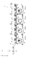
- FIG. 1 is a plan view showing an acoustic device 1 according to this embodiment.
- the audio device 1 mixes music supplied from a music reproducing device such as an analog player, a CD player, and a computer that executes music reproducing software, and outputs an audio signal corresponding to the mixed music. is a mixer.
- the audio device 1 adds a predetermined effect to the input music.
- the audio device 1 includes a housing 11, a microphone control section 12, an effect processing section 13, a master control section 14, and an equalizer control section 15, as shown in FIG.
- the housing 11 is formed in a substantially rectangular parallelepiped shape, and accommodates therein a control section (not shown) that controls the operation of the audio device 1 .
- the housing 11 has a top surface 11A, a top surface 11B, a bottom surface 11C, a left side surface 11D, a right side surface 11E, and a bottom surface (not shown).
- a microphone adjustment section 12, an effect processing section 13, a master adjustment section 14, and an equalizer adjustment section 15 are exposed on the top surface 11A.
- the upper surface 11B is provided with terminals to which a music reproducing device and a music operating device such as a DJ player can be connected.
- the three mutually orthogonal directions are +X direction, +Y direction and +Z direction.
- the +Z direction is the direction from the bottom surface toward the top surface 11A. That is, the +Z direction is a direction perpendicular to the top surface 11A.
- the +X direction is the direction from the upper surface 11B to the lower surface 11C
- the +Y direction is the direction from the left side 11D to the right side 11E.
- the direction opposite to the +X direction is the -X direction
- the direction opposite to the +Y direction is the -Y direction
- the direction opposite to the +Z direction is the -Z direction.
- Microphone control section 12 includes headphone terminal 121, volume control section 122, mixing control section 123, master effect switching section 124, master effect amount control section 125, microphone switching section 126, microphone equalizer control section 127, and microphone volume control section 128. have.
- a slide operator 711 is exposed on the microphone adjustment section 12 .
- a headphone (not shown) is connected to the headphone terminal 121 .
- the volume adjustment unit 122 adjusts the volume output from the headphones.
- the mixing adjustment unit 123 adjusts the balance of the volume output from the headphones, that is, the balance between the output volume of the channel whose CUE button is pressed and the output volume of the master channel.
- the master effect switching section 124 has six buttons.
- the master effect switching unit 124 switches effects to be applied to songs of all channels provided in the equalizer adjustment unit 15 to effects preset for the pressed buttons.
- the effects switched by the master effect switching unit 124 are, for example, effects classified as SOUND COLOR EFFECT.
- the master effect amount adjustment unit 125 adjusts the effect amount, which is the amount of effect to be applied that has been switched by the master effect switching unit 124 .
- the microphone switching unit 126 switches ON/OFF of the microphone connected to the audio device 1 .
- the microphone equalizer adjustment unit 127 adjusts the volume of the voice input from the microphone according to the frequency.
- the microphone volume adjustment unit 128 adjusts the volume of voice output from the microphone.
- the slide operator 711 constitutes a state switching mechanism 7, which will be described later.
- the slide operator 711 is slidable in the ⁇ Y directions, and switches the operation mode of the effect adjustment section 157 and the operation feeling of the effect adjustment section 157 according to the position of the slide operator 711 .
- the configuration of the state switching mechanism 7 having the slide operator 711 and the configuration of the effect adjustment section 157 will be detailed later.
- the effect processing unit 13 adds effects to the input music.
- the effect added by the effect processing unit 13 is, for example, an effect classified as BEAT EFFECT.
- the effect processing section 13 has an effect switching section 131 , a channel switching section 132 , an effect time setting section 133 , an effect amount adjusting section 134 , a magnification setting section 135 and a display section 136 .
- the effect switching unit 131 is a switch for selecting effects to be added to music.
- the channel switching unit 132 selects a channel for adding an effect to music from all the channels provided in the equalizer adjustment unit 15 .
- the effect time setting section 133 sets the time for adding the selected effect.
- the effect amount adjustment unit 134 adjusts the effect amount of the selected effect.
- the magnification setting unit 135 sets the beat magnification for synchronizing the timing of adding the effect based on the BPM of the input music.
- Examples of the beat ratio that can be set include 1 beat, 2 beats, 1/2 beats, and 1/4 beats of the BPM of the music.
- the display unit 136 displays the selected effect or the BPM of the input music. In this embodiment, the display unit 136 displays the name of the effect selected by the effect switching unit 131 , the BPM of the music, or the beat ratio set by the ratio setting unit 135 .
- the master adjustment unit 14 adjusts the entire music output from the audio device 1 .
- the master adjustment section 14 has a master volume adjustment section 141 , a level indicator 142 , a volume balance adjustment section 143 , an equalizer switching section 144 , a first characteristic switching section 145 and a second characteristic switching section 146 .
- the master volume adjustment unit 141 adjusts the volume of the entire music output from the audio device 1 .
- the level indicator 142 displays left and right output volumes of music output from the audio device 1 .
- the volume balance adjustment unit 143 adjusts the balance between left and right output volumes of music output from the audio device 1 .
- the equalizer switching unit 144 switches the equalizer curve.
- the first characteristic switching section 145 switches the curve characteristic of the volume fader 158 of the equalizer adjusting section 15 .
- the second characteristic switching unit 146 switches curve characteristics when switching is performed by the crossfader 15E, which will be described later.
- the equalizer adjustment unit 15 performs equalizer adjustment processing for each channel of music input to the audio device 1 .
- the equalizer adjuster 15 includes a first channel adjuster 15A that adjusts the first channel, a second channel adjuster 15B that adjusts the second channel, a third channel adjuster 15C that adjusts the third channel, and a fourth channel adjuster 15C. It has a fourth channel adjusting section 15D for adjusting channels and a crossfader 15E.
- the above-described music playback device and a music operation device such as a DJ player are connected to each of the channel adjustment units 15A to 15D, and each channel adjustment unit 15A to 15D can perform equalizer adjustment on the input music. is.
- Each channel adjustment section 15A-15D includes an input switching section 151, a level adjustment section 152, a level indicator 153, a high frequency band adjustment section 154, an intermediate frequency band adjustment section 155, a low frequency band adjustment section 156, an effect adjustment section 157, and a volume fader. 158 and a crossfader switching unit 159 .
- the input switching unit 151 switches input sources. Specifically, the input switching unit 151 selects an analog player connected to the phono terminal of the acoustic device 1, a CD player connected to the line terminal, and a music player such as a computer connected to the USB terminal. Switch the music playback device to be the source.
- the level adjustment unit 152 adjusts the input level of music input from the music reproduction device selected by the input switching unit 151 .
- a level indicator 153 displays the input level adjusted by the level adjusting section 152 .
- the high frequency band adjustment unit 154 adjusts the volume of the high frequency band of the input music.
- a high frequency band is, for example, a frequency band of 4649 Hz or higher.
- the medium frequency band adjustment unit 155 adjusts the volume of the medium frequency band of the input music.
- the medium frequency band is, for example, a frequency band above 284 Hz and below 4649 Hz.
- the low frequency band adjustment unit 156 adjusts the volume of the low frequency band of the input music.
- the low frequency band is, for example, a frequency band of 284 Hz or less.
- the effect adjustment unit 157 adjusts the amount of effect set in each of the channel adjustment units 15A to 15D. That is, the audio device 1 includes an effect adjustment unit 157A that is the effect adjustment unit 157 of the first channel adjustment unit 15A, an effect adjustment unit 157B that is the effect adjustment unit 157 of the second channel adjustment unit 15B, and an effect adjustment unit 157B that is the effect adjustment unit 157 of the second channel adjustment unit 15B. It has an effect adjustment section 157C, which is the effect adjustment section 157, and an effect adjustment section 157D, which is the effect adjustment section 157 of the fourth channel adjustment section 15D.
- the effect adjustment section 157 is configured with a rotary operator 2 (see FIG. 2), which will be described later.
- the volume fader 158 adjusts the volume output from the corresponding channel adjustment section among the channel adjustment sections 15A to 15D.
- the crossfader switching unit 159 switches the output destination of the corresponding channel adjustment unit among the adjustment units 15A to 15D to either the A side (left side) or the B side (right side) of the crossfader 15E.
- the crossfader 15E has an operator that can move left and right. As the operator is moved to the left, the ratio of the volume of the channel switched to the A side in the volume output from the audio device 1 increases. Further, as the operator is moved to the right, the ratio of the volume of the channel switched to the B side in the volume output from the audio device 1 increases.
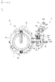
- FIG. 2 is a plan view showing the rotary operator 2 and the state switching mechanism 7 provided on the housing 11.
- the acoustic device 1 includes a rotary operator 2 in which a knob 43 is exposed from the top surface 11A (see FIG. 1) to the outside of the housing 11, and an operation feeling switching mechanism provided inside the housing 11. 6 and a state switching mechanism 7 .
- the rotary operator 2 is an operator that is rotated by the user.
- the rotary operator 2 constitutes each of the effect adjustment sections 157A to 157D. That is, the acoustic device 1 has four rotary operators 2 arranged along the +Y direction.
- the operational feeling switching mechanism 6 is provided for each of the plurality of rotary operators 2 .
- the operational feeling switching mechanism 6 switches the operational feeling when the rotary operator 2 is operated.
- the state switching mechanism 7 switches the state of the rotary operator 2 , specifically, switches the operation mode of the rotary operator 2 .
- the operating mode of the rotary operator 2 can also be said to be the operating mode of the acoustic device 1 having the rotary operator 2 .
- the state switching mechanism 7 switches the operation mode of each rotary operator 2 and operates each operation feeling switching mechanism 6 according to a user's switching operation on the state switching mechanism 7 .
- the rotary operator 2, the operational feeling switching mechanism 6, and the state switching mechanism 7 will be described below.
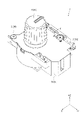
- FIG. 3 is a perspective view showing the rotary operator 2.
- FIG. FIG. 4 is a perspective view showing the rotary operator 2 with the cover member 38 and the fixing member 39 of the housing 3 separated from each other.
- FIG. 5 is a plan view of the rotary operator 2 from which the cover member 38 and the fixing member 39 are removed, as seen from the +Z direction.
- the rotary operator 2 includes a housing 3, an operator main body 4, and a regulation switching mechanism 5. As shown in FIGS.
- FIG. 6 is a plan view showing the housing section 3 viewed from the +Z direction.
- the members constituting the rotary operator 2 some members that engage with the housing portion 3 are illustrated together with the housing portion 3 .
- the housing part 3 is formed in a substantially rectangular parallelepiped shape, and supports the operator main body 4 , the regulation switching mechanism 5 and the operational feeling switching mechanism 6 .
- the housing section 3 includes a housing body 31 in which the operator body 4 is arranged, and also has a cover member 38 and a fixing member 39 as shown in FIGS. Prepare.
- the housing body 31 has a first placement portion 32 and a second placement portion 33, as shown in FIGS.
- the first placement portion 32 is formed in the housing portion 3 in a substantially rectangular shape when viewed from the +Z direction, and is a portion in which the operator main body 4 and part of the operational feeling switching mechanism 6 are arranged.
- the first arrangement portion 32 is open in the +Z direction.
- the first arrangement portion 32 has guide portions 321 , 322 , 323 and fixing portions 324 , 325 .
- the guide portions 321 to 323 are recesses that are provided along the +Z direction periphery of the first arrangement portion 32 and open in the +Z direction.
- the guide portion 321 is provided at the position in the -X direction
- the guide portion 322 is provided at the position in the +X direction
- the guide portion 323 is provided at the position in the -Y direction.
- a guided portion 612 of a click plate 61 of the operation feeling switching mechanism 6, which will be described later, is arranged on the guide portions 321 to 323. As shown in FIG.
- the guide portions 321 to 323 have a click plate 61 that engages with the movement base 62 when the movement base 62 described later of the operation feeling switching mechanism 6 is rotated clockwise or counterclockwise when viewed from the +Z direction. It guides the movement of the click plate 61 in the ⁇ Z directions while suppressing it from rotating together with the movement base 62 .
- the fixing portions 324 and 325 are portions for fixing the fixing member 39 that fixes the cover member 38 to the housing body 31 .
- the fixing portions 324 and 325 are screw holes into which the fixing member 39, which is a screw, is screwed.
- the second arrangement portion 33 is provided in the +Y direction with respect to the first arrangement portion 32, and is a portion where the regulation switching mechanism 5 is arranged.
- the second arrangement portion 33 has a support portion 34 , a lever support portion 35 , a locking portion 36 and a range defining portion 37 .
- the support portion 34 supports the contactor 51 of the regulation switching mechanism 5, the holding member 54, and the like.
- the support portion 34 penetrates the housing portion 3 along the +Z direction.
- the support portion 34 has a holding portion 341 , guide portions 342 and 344 and guide holes 343 .
- the holding portion 341 is provided on the inner surface of the support portion 34 in the -X direction.
- the holding portion 341 holds the +Y-direction end of the second biasing member 53, which will be described later.
- the holding portion 341 and the second biasing member 53 are arranged inside the holding member 54 arranged inside the support portion 34 .
- the guide portion 342 is provided in the +Y direction with respect to the holding portion 341 and is provided continuously with the holding portion 341 in the +Y direction with respect to the holding portion 341 .
- Each guide portion 342 guides the movement of the holding member 54 in the ⁇ Y directions.
- the guide hole 343 is an opening that communicates between the first placement portion 32 and the second placement portion 33 .
- the guide hole 343 is elongated in the +Z direction, and the contact portion 515 of the contactor 51 arranged inside the support portion 34 is inserted through the guide hole 343 toward the first arrangement portion 32 .
- the inner diameter of the guide hole 343 in the +X direction substantially matches the dimension of the contact portion 515 in the +X direction.
- the guide portion 344 is a concave portion that is provided at a position in the +Y direction on the periphery of the second placement portion 33 and opens in the +Y direction and the +Z direction.
- the guide portion 344 supports the contactor 51 so as to be movable in the ⁇ Y directions and also movable in the ⁇ Z directions.
- the lever support portion 35 rotatably supports the switching member 55 of the regulation switching mechanism 5 . More specifically, the lever support portion 35 supports the switching member 55 so as to be rotatable clockwise and counterclockwise when viewed from the +Z direction.
- the locking portion 36 is provided on the lever support portion 35 and locks one end of a third biasing member 56 that is a torsion coil spring that biases the switching member 55 counterclockwise. The other end of the third biasing member 56 is locked to the switching member 55 .
- Two range defining portions 37 are provided at positions in the +X direction with respect to the lever support portion 35 .
- the range defining portions 37 are provided apart from each other in the +Y direction.
- the range defining portion 37 sandwiches the switching member 55 supported by the lever support portion 35 in the +Y direction, thereby defining the rotation range of the switching member 55 .
- the cover member 38 is fixed to the housing body 31 from the +Z direction by two fixing members 39, as shown in FIG.
- the cover member 38 is a member that covers a part of the operation feeling switching mechanism 6 described later in the +Z direction and holds the part of the operation feeling switching mechanism 6 inside the first arrangement portion 32 .
- the cover member 38 has a circular opening 381 through which a portion of the rotating body main body 44 is inserted, and two hole portions 382 through which the fixing member 39 is inserted.
- FIG. 7 is a perspective view showing the operator main body 4.
- the operator main body 4 is a rotary volume that is operated by a user and outputs a rotation angle with respect to a reference position.
- the operator main body 4 includes a pedestal portion 41 and a rotating body 42 .
- the pedestal portion 41 supports the rotating body 42 so as to be rotatable around the rotating axis Rx along the +Z direction, and is fixed to the substrate PL.
- the pedestal portion 41 has a detection portion (not shown) that detects the rotation angle of the rotating body 42 . Note that the configuration of the detection unit that detects the rotation angle can employ a known technique, so the description is omitted.
- the board PL is a part of the control section that constitutes the acoustic device 1, or a board that is electrically connected to the control section.
- the rotating body 42 is rotated by the user about the rotation axis Rx.
- the rotating body 42 has a knob 43 to be gripped by the user, and a rotating body main body 44 to which the knob 43 is attached and which is rotated integrally with the knob 43 .
- the knob 43 has an indicator line 431 that indicates the rotational position of the rotating body 42 . As shown in FIG. 5, when the position of the rotating body 42 when the pointing line 431 is parallel to the -X direction and faces the -X direction is taken as the reference position, the rotating body 42 rotates clockwise from the reference position, for example. For example, it is configured to be able to rotate approximately 150 degrees counterclockwise from the reference position.
- the reference position includes a range from the reference position when viewed from the +Z direction to a position where rotation of the rotating body 42 in the clockwise direction about the rotation axis Rx is permitted, and a range from the reference position when viewed from the +Z direction.
- This is the position where the length is equal to the range up to the position where the rotation of the rotating body 42 in the counterclockwise direction about the rotation axis Rx is allowed.
- the reference position is a position where the rotation range from the reference position to the clockwise rotation limit and the rotation range from the reference position to the counterclockwise rotation limit have the same length.
- a reference position is a predetermined position in the present disclosure. Note that, in the following description, when viewed from the +Z direction, the clockwise direction is the +D direction, and the counterclockwise direction is the -D direction.
- the rotary body main body 44 has a cylindrical portion 45 formed in a cylindrical shape around the rotary axis Rx.
- the cylindrical portion 45 has a fitting portion 451 on the +Z direction surface.
- a projecting portion 614 (see FIG. 17) provided on a click plate 61 to be described later is fitted into the fitting portion 451 as the rotating body 42 rotates.
- the cylindrical portion 45 has an outer peripheral surface 45A centered on the rotation axis Rx, a concave portion 46 recessed in a direction from the outer peripheral surface 45A toward the rotation axis Rx, and a radial direction centered on the rotation axis Rx from the outer peripheral surface 45A. and path forming portions 47 and 48 projecting outward.
- FIG. 8 is a side view of the rotating body 42 viewed from the +Y direction.
- the contact 51 is fitted into the recess 46 when the rotating body 42 is positioned at the reference position.
- the concave portion 46 is provided in the center of the cylindrical portion 45 in the +Z direction.
- the concave portion 46 has a bottom portion 461 and inclined portions 462 and 463 .
- the bottom portion 461 is a portion located closest to the rotation axis Rx in the concave portion 46 and is formed flat.
- a contact portion 515 (see FIGS. 9 and 10) that contacts the outer peripheral surface 45A of the contactor 51 can be arranged on the bottom portion 461 .
- the inclined portion 462 is arranged in the +D direction with respect to the bottom portion 461 .
- the inclined portion 462 is inclined in a direction away from the rotation axis Rx toward the +D direction. That is, the inclined portion 462 is inclined so as to be positioned radially outward from the rotation axis Rx as it goes in the +D direction.
- the inclined portion 462 guides the contact portion 515, which relatively moves in the +D direction with respect to the rotating body 42, to the first path RT11 of the path forming portion 47 when the rotating body 42 is rotated in the -D direction.
- the inclined portion 463 is arranged in the ⁇ D direction with respect to the bottom portion 461 .
- the inclined portion 463 is inclined in a direction away from the rotation axis Rx toward the -D direction. That is, the inclined portion 463 is inclined so as to be located radially outward from the rotation axis Rx as it goes in the -D direction.
- the inclined portion 463 guides the contact portion 515, which relatively moves in the ⁇ D direction with respect to the rotating body 42, to the first path RT21 of the path forming portion 48 when the rotating body 42 is rotated in the +D direction.
- the path forming portions 47 and 48 protrude radially outward from the outer peripheral surface 45A, and form movement paths RT1 and RT2 of the contact portion 515 (see FIGS. 9 and 10) when the rotating body 42 is rotated. . That is, the rotating body 42 is tilted with respect to the circumferential direction about the rotating shaft Rx, and moves along a movement path RT1 along which the contactor 51 moves along the rotating shaft Rx according to the rotation of the rotating body 42. It has a cylindrical cam structure provided with RT2. As shown in FIGS. 7 and 8, the path forming portions 47 and 48 are formed symmetrically about the concave portion 46. As shown in FIGS.
- the path forming portion 47 forms a movement path RT1 of the contact portion 515 when the rotating body 42 is rotated in the rotation range from the reference position to the rotation limit in the -D direction.
- the path forming portion 47 is formed continuously with the inclined portion 462 .
- the path forming portion 47 contacts the ⁇ Z direction portion of the contact portion 515 .
- the rotation range from the reference position to the rotation limit in the -D direction will be referred to as the counterclockwise side range of the rotating body 42 .
- the rotation range from the reference position to the rotation limit in the +D direction is referred to as the clockwise side range of the rotating body 42 .
- the movement route RT1 includes a first route RT11 and a second route RT12.
- the first path RT11 is formed continuously with the inclined portion 462 of the concave portion 46 .
- the first route RT11 is inclined so as to be positioned in the +Z direction as it goes in the +D direction. That is, the first route RT11 is inclined with respect to the circumferential direction about the rotation axis Rx.
- the +D direction end of the first route RT11 is connected to the second route RT12. Therefore, when the rotating body 42 is rotated in the -D direction, the contact portion 515 moves in the +D direction along the first path RT11 and reaches the second path RT12.
- the second route RT12 is a route that is inclined with respect to the circumferential direction around the rotation axis Rx so as to be positioned in the -Z direction as it goes in the +D direction, and is formed longer in the +D direction than the first route RT11. It is That is, the second route RT12 is inclined with respect to the circumferential direction about the rotation axis Rx.
- the contact portion 515 moves further in the +D direction than the second route RT12.
- the position of the contactor 51 in the +Z direction at this time is the same as the position of the contactor 51 in the +Z direction when the contact portion 515 is arranged on the bottom portion 461 by the biasing force of the first biasing member 52 described later.
- the +D direction end of the path forming portion 47 is centered on the rotation axis Rx, and is more ⁇ than the ⁇ Z direction end of the contact portion 515 when the contactor 51 is arranged at the second position. arranged in the Z direction. Therefore, when the rotating body 42 is rotated most in the ⁇ D direction and then rotated in the +D direction, the contact portion 515 contacts the surface of the path forming portion 47 in the +Z direction, and the contact portion 515 contacts the second path RT12. is moved along.
- the contact portion 515 may be arranged at a predetermined position on the second route RT12 when the rotating body 42 is most rotated in the -D direction.
- the second route RT12 is provided radially inward about the rotation axis Rx from the first route RT11. That is, the second route RT12 is provided at a position closer to the rotation axis Rx than the first route RT11.
- the second path RT12 guides the contact portion 515 moving in the -D direction to the restricting portion 481 of the path forming portion 48 when the rotating body 42 is rotated in the +D direction in the counterclockwise range.
- the path forming portion 48 forms a movement path RT2 of the contact portion 515 when the rotating body 42 is rotated in the rotation range from the reference position to the rotation limit in the +D direction.
- the path forming portion 48 is formed continuously with the inclined portion 463 .
- the path forming portion 48 contacts the +Z direction portion of the contact portion 515 .
- the range from the reference position to the rotation limit of the rotating body 42 in the +D direction is referred to as the clockwise side range of the rotating body 42 .
- the movement route RT2 includes a first route RT21 and a second route RT22.
- the first path RT21 is formed continuously with the inclined portion 463 of the concave portion 46 .
- the first route RT21 is inclined so as to be positioned in the -Z direction as it goes in the -D direction. That is, the first route RT21 is inclined with respect to the circumferential direction about the rotation axis Rx.
- the ⁇ D direction end of the first route RT21 is continuous with the second route RT22. Therefore, when the rotating body 42 is rotated in the +D direction, the contact portion 515 moves in the -D direction along the first route RT21 and reaches the second route RT22.
- the first route RT21 is located radially outside of the second route RT22 about the rotation axis Rx.
- the second route RT22 is a route that is inclined with respect to the circumferential direction around the rotation axis Rx so as to be positioned in the +Z direction as it goes in the -D direction, and is longer in the -D direction than the first route RT21. formed.
- the contact portion 515 moves further in the -D direction than the second route RT22.
- the position of the contactor 51 in the +Z direction at this time is the same as the position when it is arranged at the second position by the biasing force of the first biasing member 52, which will be described later.
- the ⁇ D direction end of the path forming portion 48 is centered on the rotation axis Rx and is arranged in the ⁇ Z direction relative to the +Z direction end of the contact portion 515 arranged at the second position.
- the contact portion 515 contacts the surface of the path forming portion 48 in the -Z direction, and the second path It is moved along RT22.
- the contact portion 515 may be arranged at a predetermined portion on the second route RT22 when the rotating body 42 is most rotated in the +D direction.
- the second path RT22 guides the contact portion 515 moving in the +D direction to the restricting portion 471 of the path forming portion 47 when the rotating body 42 is rotated in the -D direction in the clockwise range.
- the path forming portion 47 further has a restricting portion 471 provided at the end of the path forming portion 47 in the -D direction.
- the restricting portion 471 is provided in the ⁇ Z direction with respect to the concave portion 46 .
- the restricting portion 471 has a restricting surface 472 and a guide surface 473 .
- the restricting surface 472 is substantially perpendicular to the circumferential direction about the rotation axis Rx. In the clockwise range of the rotating body 42, when the rotating body 42 is rotated in the -D direction and reaches the reference position, the restricting surface 472 has a contact that relatively moves in the +D direction with respect to the rotating body 42. Child 51 comes into contact.
- the restricting portion 471 restricts the contactor 51 from moving further in the +D direction, and restricts the rotating body 42 from rotating in the -D direction from the reference position.
- the position of the contactor 51 when the contact portion 515 contacts the restricting portion 471 is defined as the first position in the clockwise range of the rotating body 42 .
- the first position in the clockwise range is in the ⁇ Z direction from the position of contact 51 when contact portion 515 is placed on bottom portion 461 .
- the position of the contactor 51 when the contact portion 515 is arranged on the bottom portion 461 is the second position.
- the guide surface 473 guides the contactor 51 moved along the movement path RT2 formed by the path forming portion 48 and the outer peripheral surface 45A to the restriction surface 472 .
- Guide surface 473 includes a first guide surface 474 and a second guide surface 475 .
- the first guide surface 474 is continuous with the second route RT22 and the outer peripheral surface 45A.
- the first guide surface 474 intersects the circumferential direction about the rotation axis Rx so as to be located radially outward about the rotation axis Rx toward the +D direction.
- the second guide surface 475 is provided between the first guide surface 474 and the regulation surface 472 and is continuous with the first guide surface 474 and the regulation surface 472 .
- the second guide surface 475 intersects the circumferential direction about the rotation axis Rx so as to be positioned radially outward about the rotation axis Rx toward the +D direction.
- the inclination angle of the second guide surface 475 with respect to the circumferential direction about the rotation axis Rx is larger than the inclination angle of the first guide surface 474 with respect to the circumferential direction.
- the contactor 51 that has reached the guide surface 473 from the second path RT22 further moves in the +D direction relative to the rotating body 42, thereby moving in the +Y direction away from the rotating body 42 along the guide surface 473. While moving, it reaches the position where it contacts the regulation surface 472 . In this state, when the turning force in the -D direction with respect to the rotating body 42 is reduced, the contact portion 515 moves the path forming portion 48 forming the second path RT22 to +Z direction due to the biasing force of the first biasing member 52 described later. The bottom 461 is reached by climbing over in the direction. That is, the contactor 51 reaches the second position.
- the path forming portion 48 further includes a restricting portion 481 provided at the +D direction end of the path forming portion 48 , similarly to the path forming portion 47 .
- the restricting portion 481 is provided in the +Z direction with respect to the concave portion 46 .
- the restricting portion 481 has a restricting surface 482 and a guide surface 483 .
- the restricting surface 482 is substantially orthogonal to the circumferential direction about the rotation axis Rx. In the counterclockwise range of the rotating body 42, the restricting surface 482 moves relative to the rotating body 42 in the -D direction when the rotating body 42 is rotated in the +D direction and reaches the reference position.
- the contactor 51 makes contact.
- the restricting portion 481 restricts the contactor 51 from moving further in the -D direction, and restricts the rotating body 42 from rotating in the +D direction from the reference position.
- the position of the contactor 51 when the contact portion 515 contacts the restricting portion 481 is the first position in the counterclockwise range of the rotating body 42 .
- the first position in the counterclockwise range is in the +Z direction with respect to the second position.
- Guide surface 483 guides the contactor 51 that has moved along the movement path RT ⁇ b>1 formed by the path forming portion 47 and the outer peripheral surface 45 ⁇ /b>A to the restriction surface 482 .
- Guide surface 483 includes a first guide surface 484 and a second guide surface 485 .
- the first guide surface 484 is continuous with the second route RT22 and the outer peripheral surface 45A.
- the first guide surface 484 intersects the circumferential direction about the rotation axis Rx so as to be located radially outward about the rotation axis Rx toward the -D direction.
- the second guide surface 485 is provided between the first guide surface 484 and the regulation surface 482 and is continuous with the first guide surface 484 and the regulation surface 482 .
- the second guide surface 485 intersects the circumferential direction about the rotation axis Rx so as to be located radially outward about the rotation axis Rx toward the +D direction.
- the inclination angle of the second guide surface 485 with respect to the circumferential direction about the rotation axis Rx is larger than the inclination angle of the first guide surface 484 with respect to the circumferential direction.
- the contactor 51 that has reached the guide surface 483 from the second path RT12 further moves relative to the rotating body 42 in the -D direction, and moves away from the rotating body 42 along the guide surface 483 in the +Y direction. While moving, it reaches a position where it contacts the regulation surface 481A.
- the contact portion 515 moves the path forming portion 47 that forms the second path RT12 to -Z
- the bottom 461 is reached by climbing over in the direction. That is, the contactor 51 reaches the second position.
- the outer peripheral surface 45A of the rotating body 42 is provided with the movement paths RT1 and RT2 inclined with respect to the circumferential direction about the rotating axis Rx. Rotate around the center.
- the contact portion 515 that moves along the movement paths RT1 and RT2 will be described in detail later.
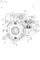
- FIG. 10 is a plan view showing the regulation switching mechanism 5 as seen from the +Z direction.
- 9 and 10 are diagrams showing the regulation switching mechanism 5 in a state of being engaged with the operator main body 4.
- the regulation switching mechanism 5 has a regulated state in which the rotation of the rotating body 42 is restricted by the regulating portions 471 and 481 and a non-restricted state in which the rotation of the rotating body 42 is not restricted according to the switching operation of the state switching mechanism 7 . switch.
- the regulation switching mechanism 5 switches between a regulated state in which the rotation of the rotating body 42 is restricted at the reference position and a non-restricted state in which the rotation of the rotating body 42 is not restricted at the reference position.
- the regulation switching mechanism 5 includes a contactor 51, a first biasing member 52, a second biasing member 53, a holding member 54, a switching member 55, and a third biasing member 56, as shown in FIGS. .
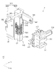
- FIG. 11 is an exploded perspective view of the regulation switching mechanism 5 viewed from the +X direction and the -Y direction.
- FIG. 12 is an exploded perspective view of the regulation switching mechanism 5 viewed from the -X direction and the +Y direction. 11 and 12, illustration of the switching member 55 and the third biasing member 56 is omitted.
- the contactor 51 is provided so as to be able to come into contact with the rotating body 42 and comes into contact with the regulating portions 471 and 481 to restrict the rotation of the rotating body 42 . As the rotating body 42 rotates, the contactor 51 moves relative to the rotating body 42 in the ⁇ D directions along the movement paths RT1 and RT2.
- the contactor 51 moves in the ⁇ Z directions along the movement paths RT1 and RT2 as the rotating body 42 rotates.
- the +Z direction and the ⁇ Z direction are directions along the rotation axis Rx.
- the contactor 51 is formed in a substantially cross shape when viewed from the +X direction.
- the contactor 51 has a contactor main body 511 , a contact portion 515 and a projecting portion 516 .
- the contactor main body 511 is formed in a substantially rectangular shape when viewed from the +X direction or the ⁇ X direction. As shown in FIG. 12, the contactor main body 511 has a substantially rectangular placement portion 512 elongated in the +Y direction, and inserted portions 513 and 514 formed continuously with the placement portion 512 .
- the arrangement portion 512 is a recess opening in the -X direction.
- the first biasing member 52 provided on the holding member 54 is arranged inside the arrangement portion 512 when the contactor 51 and the holding member 54 are combined.
- the inserted portion 513 is provided in the +Z direction with respect to the placement portion 512 .
- the inserted portion 513 is open in the ⁇ X direction and also in the +Z direction, and is formed continuously with the placement portion 512 .
- the first locking portion 5432 of the holding member 54 is inserted into the inserted portion 513 .
- the inserted portion 514 is provided in the ⁇ Z direction with respect to the placement portion 512 .
- the inserted portion 514 is open in the ⁇ X direction and also in the ⁇ Z direction, and is formed continuously with the placement portion 512 .
- the second locking portion 5434 of the holding member 54 is inserted into the inserted portion 514 .
- the contact portion 515 is a substantially quadrangular prism-shaped portion protruding from the contactor main body 511 in the -Y direction.
- the contact portion 515 is inserted through the guide hole 343 (see FIG. 5) provided in the housing portion 3 and comes into contact with the outer peripheral surface 45A of the rotating body 42 . That is, the -Y direction end surface of the contact portion 515 is a contact surface that can contact the outer peripheral surface 45A of the contactor 51 .
- the projecting portion 516 is a substantially quadrangular prism-shaped portion projecting in the +Y direction from the contactor main body 511 .
- the projecting portion 516 is inserted through the guide portion 344 (see FIG. 5) provided on the housing portion 3 along the +Y direction.
- the first biasing member 52 is provided on the holding member 54 as shown in FIG.
- the first biasing member 52 biases the contactor 51 in the +Z direction and the -Z direction to maintain the contactor 51 at the same position as the second position in the +Z direction.
- the first biasing member 52 biases the contactor 51 in the -Z direction.
- the first biasing member 52 biases the contactor 51 in the +Z direction.
- the first biasing member 52 biases the contactor 51 in the ⁇ Z direction from the first position to the second position in the counterclockwise range, and also biases the contactor 51 from the first position to the second position in the clockwise range. to bias the contact 51 in the +Z direction.
- the first biasing member 52 is configured by a compression coil spring.
- the second biasing member 53 is provided on the holding member 54 as shown in FIG.
- the second biasing member 53 biases the contactor 51 in the ⁇ Y direction via the holding member 54 . That is, the second biasing member 53 biases the contactor 51 in the direction toward the rotation axis Rx of the rotating body 42 via the holding member 54 .
- the second biasing member 53 is configured by a compression coil spring.
- the +Y direction end of the second biasing member 53 is held by the holding portion 341 (see FIG. 6) of the housing portion 3, and the -Y direction end is held by the second holding portion 544 of the holding member 54. be done.
- the holding member 54 holds the first biasing member 52 and the second biasing member 53 and applies the biasing force of the first biasing member 52 and the biasing force of the second biasing member 53 to the contact 51. . Specifically, the holding member 54 maintains the position of the contactor 51 by the biasing force of the first biasing member 52 so that the contact portion 515 is arranged at the same position as the concave portion 46 in the +Z direction. Further, the holding member 54 maintains a state in which the contact portion 515 is in contact with the outer peripheral surface 45A due to the biasing force of the second biasing member 53 .
- the holding member 54 has a first projecting portion 541, a second projecting portion 542, a first holding portion 543, a second holding portion 544, and a pressed portion 545, as shown in FIGS.
- the first protrusion 541 protrudes in the +X direction from the +Z direction end of the holding member 54 .
- a concave portion 5411 recessed in the -X direction is provided on the +X direction end face of the first projecting portion 541 .
- a convex portion (not shown) of the housing portion 3 is inserted into the concave portion 5411, thereby guiding the slide of the holding member 54 in the ⁇ Y direction and suppressing the movement of the holding member 54 in the ⁇ Z direction. be done.
- the second protrusion 542 protrudes in the ⁇ Y direction from the +Z direction end of the holding member 54 .
- the second protruding portion 542 is inserted into a concave portion (not shown) of the housing portion 3 .
- the first holding portion 543 holds the first biasing member 52 .
- the first holding portion 543 has a first holding piece 5431, a first locking portion 5432, a second holding piece 5433 and a second locking portion 5434, as shown in FIG.
- the first holding piece 5431 and the second holding piece 5433 are provided on the +X direction portion of the holding member 54 so as to be separated from each other in the +Z direction.
- the first holding piece 5431 is provided apart from the second holding piece 5433 in the +Z direction.
- the first holding piece 5431 is inserted into the +Z direction end of the first biasing member 52
- the second holding piece 5433 is inserted into the ⁇ Z direction end of the first biasing member 52 .
- FIG. 13 is a diagram showing a cross section of the rotating body 42 and the regulation switching mechanism 5 along the YZ plane.
- the first locking portion 5432 protrudes in the +X direction from the +Z direction portion of the first holding piece 5431 .
- the second locking portion 5434 protrudes in the +X direction from the -Z direction portion of the second holding piece 5433 .
- FIG. 13 when the contactor 51 is moved in the +Z direction, the +Z-direction end of the first biasing member 52 contacts the -Z-direction surface of the first locking portion 5432, The first locking portion 5432 locks the first biasing member 52 .
- the first biasing member 52 is restricted from moving in the +Z direction together with the contactor 51, and the first biasing member 52 generates a biasing force that biases the contactor 51 in the -Z direction. That is, when the contactor 51 moves in the +Z direction, the first biasing member 52 biases the contactor 51 in the -Z direction.
- the ⁇ Z direction end of the first biasing member 52 contacts the +Z direction surface of the second locking portion 5434 , and the second locking portion 5434 locks the first biasing member 52 .
- the first biasing member 52 is restricted from moving in the ⁇ Z direction together with the contactor 51, and the first biasing member 52 generates a biasing force that biases the contactor 51 in the +Z direction. That is, when the contactor 51 moves in the -Z direction, the first biasing member 52 biases the contactor 51 in the +Z direction.
- the second holding portion 544 holds the second biasing member 53 as shown in FIG.
- the second holding portion 544 has a first wall portion 5441 and a second wall portion 5443 facing each other in the +Y direction.
- the first wall portion 5441 has an insertion portion 5442 inserted into the -Y direction end of the second biasing member 53 arranged along the +Y direction.
- the second wall portion 5443 is provided in the +Y direction with respect to the first wall portion 5441 .
- a holding portion 341 (see FIG. 6) of the housing portion 3 is arranged between the first wall portion 5441 and the second wall portion 5443 in the +Y direction. As described above, the ⁇ Y direction end of the holding portion 341 locks the +Y direction end of the second biasing member 53 .
- the holding member 54 and the contactor 51 are biased in the -Y direction by the second biasing member 53 . That is, the holding member 54 and the contactor 51 are urged by the second urging member 53 in the direction of approaching the rotation axis Rx of the rotating body 42 .
- the pressed portion 545 is provided on the -Y direction surface of the second wall portion 5443, as shown in FIGS.
- the pressed portion 545 is pressed in the +Y direction by the switching member 55 rotated counterclockwise when viewed from the +Z direction.
- the holding member 54 is moved in the +Y direction against the biasing force of the second biasing member 53, and the contactor 51 is moved in the +Y direction.
- the contactor 51 is separated from the rotating body 42 to such an extent that the contact portion 515 does not come into contact with the rotating body 42, and the rotating body 42 is placed in a non-restricted state in which the rotation of the rotating body 42 is not restricted at the reference position. can be switched.
- the switching member 55 shifts between a position where the contactor 51 can come into contact with the rotating body 42 of the rotary operator 2 and a position where the contactor 51 cannot come into contact with the rotating body 42.
- the position of the contactor 51 is switched.
- the switching member 55 is supported by the lever support portion 35 (see FIGS. 5 and 6) of the housing portion 3 so as to be rotatable clockwise and counterclockwise when viewed from the +Z direction. It is a lever member that rotates as the slide member 72 slides to switch the position of the contactor 51 .
- the switching member 55 has a pressing portion 551 , an engaging portion 552 and a locking portion 553 .
- the pressing portion 551 presses the pressed portion 545 in the +Y direction to separate the contactor 51 from the rotating body 42 when the switching member 55 rotates counterclockwise when viewed from the +Z direction.
- the engaging portion 552 engages with a slide member 72 of the state switching mechanism 7, which will be described later.
- the engaging portion 552 is provided at the end of the switching member 55 opposite to the end where the pressing portion 551 is provided, and is a columnar boss that protrudes in the ⁇ Z direction.
- the locking portion 553 locks the end of the third biasing member 56 .
- the third biasing member 56 is a torsion coil spring provided on the lever support portion 35 (see FIGS. 5 and 6). One end of the third biasing member 56 is locked by the locking portion 36 (see FIGS. 5 and 6), and the other end of the third biasing member 56 is locked by the locking portion 553 of the switching member 55. be.
- the third biasing member 56 biases the switching member 55 counterclockwise when viewed from the +Z direction. As described above, the switching member 55 rotated counterclockwise presses the holding member 54 in the +Y direction, thereby separating the contactor 51 from the rotating body 42 in the +Y direction. That is, the third biasing member 56 biases the contactor 51 in the +Y direction away from the rotating body 42 .
- the slide member 72 causes the switching member 55 to move against the biasing force of the third biasing member 56 when viewed from the +Z direction. Rotate clockwise. Therefore, the pressing portion 551 is separated from the pressed portion 545, the holding member 54 and the contactor 51 are movable in the -Y direction by the biasing force of the second biasing member 53, and the contact portion 515 is rotated. It comes into contact with the cylindrical portion 45 of the moving body 42 .
- FIG. 14 is a schematic diagram showing the position of the contact portion 515 when the rotating body 42 is rotated in the counterclockwise range.
- the contactor 51 is arranged at the second position where the contact portion 515 is arranged on the bottom portion 461 .
- the contact portion 515 moves from the bottom portion 461 through the inclined portion 462 as shown at the position PS1 in FIG. to reach the first route RT11.
- the contact portion 515 When the contact portion 515 is positioned on the inclined portion 462 or the first path RT11, and the rotating body 42 is rotated in the +D direction and the contact portion 515 relatively moves in the -D direction, the contact portion 515 is , back to bottom 461 .
- the contact portion 515 moves along the first path RT11 as shown at a position PS2 in FIG. 14, for example. to reach the second route RT12.
- the first biasing member 52 applies a biasing force in the ⁇ Z direction to the contactor 51, and the contact portion 515 is pressed against the path forming portion 47 in the ⁇ Z direction.
- the contact portion 515 is moved to the second path RT12, for example, as indicated by the position PS3 in FIG.
- the first biasing member 52 applies a biasing force in the ⁇ Z direction to the contact portion 515.
- the contactor 51 is arranged in the +Z direction from the second reference position, the contactor 51 is biased in the -Z direction by the first biasing member 52 .
- the biasing force in the +Z direction is applied to the contact portion 515 by the first biasing member 52 . That is, if the contactor 51 is arranged in the -Z direction from the second reference position, the contactor 51 is biased in the +Z direction by the first biasing member 52 .
- the contact portion 515 when the contact portion 515 reaches the rotation limit in the +D direction, the contact portion 515 is arranged in the +D direction with respect to the path forming portion 47 .
- the position of the contactor 51 in the +Z direction at this time is the same as the second position. More specifically, when the contact portion 515 is moved in the +D direction along the second path RT12 and reaches the same position in the +Z direction as the contact portion 515 in the second position, it moves in the -D direction. As the rotating body 42 rotates, the contact portion 515 is moved in the +D direction while being separated from the path forming portion 47 .
- the path between the position where the contact portion 515 is separated from the path forming portion 47 and the rotation limit of the contact portion 515 in the +D direction is along the circumferential direction about the rotation axis Rx. .
- the second route RT12 is provided at a position closer to the rotation axis Rx than the first route RT11. Therefore, when the contactor 51 reaches the second path RT12 from the first path RT11, the biasing force of the second biasing member 53 causes the contactor 51 to move slightly in the ⁇ Y direction, which is the rotation axis Rx side.
- the contactor 51 moves from the second path RT12 to the first path RT11. is regulated, and movement of the contactor 51 on the second route RT12 is permitted. Therefore, when the rotating body 42 is rotated in the +D direction, the contact portion 515 reaches the position PS4 in FIG. 14, for example.
- the contactor 51 When the rotating body 42 is rotated in the +D direction and reaches the guide surface 483 while the contact portion 515 is arranged on the second path RT12, the contactor 51 is moved away from the rotating body 42 by the guide surface 483. It is moved in the +Y direction to separate.
- the contact portion 515 contacts the restricting surface 482 as shown at the position PS5 in FIG.
- a position PS5 in contact with the restricting portion 481 is the first position in the above-described counterclockwise range. As a result, the movement of the contact portion 515 relative to the rotating body 42 in the -D direction is restricted, and the rotation of the rotating body 42 in the +D direction is restricted.
- the contactor 51 When the contactor 51 is arranged at the first position, the ⁇ Y direction end surface of the contact portion 515 is arranged in the +Y direction relative to the path forming portion 47 . Therefore, the contactor 51 can move over the path forming portion 47 in the direction from the first position to the second position, that is, in the -Z direction. Therefore, when the user releases the knob 43 to reduce the turning force in the +D direction with respect to the turning body 42, the contact portion 515 moves in the -Z direction due to the biasing force of the first biasing member 52. and return to the bottom 461 . That is, the contactor 51 returns to the second position. As a result, the contact portion 515 can move relative to the rotating body 42 in the ⁇ D directions, and the rotating body 42 can rotate in the ⁇ D directions.
- the contact portion 515 moves toward the inclined portion 463 . It moves relative to the rotating body 42 in the ⁇ D direction along the first path RT21 and the second path RT22 relative to the rotating body 42 . Then, when the rotating body 42 is rotated in the ⁇ D direction and the contact portion 515 that has moved along the second path RT22 and the guide surface 473 reaches the restricting portion 471, the restricting portion 471 moves the rotating body 42 to the ⁇ D direction. Rotation in the direction is restricted.
- the position of the contactor 51 when the contact portion 515 contacts the restricting portion 471 is the first position in the clockwise range described above.
- the contact portion 515 moves in the +Z direction due to the biasing force of the first biasing member 52, and the contact 51 moves to the second position. return to position.
- the contact portion 515 can move relative to the rotating body 42 in the ⁇ D directions, and the rotating body 42 can rotate in the ⁇ D directions.
- the contactor 51 is moved in the +Y direction as it advances in the +D direction along the guide surface 473, when the contactor 51 is arranged at the first position where it contacts the restricting portion 471, the The child 51 can climb over the path forming portion 47 and move from the first position to the second position. Similarly, the contactor 51 is moved in the +Y direction as it moves along the guide surface 483 in the -D direction. The contactor 51 can move over the path forming portion 48 from the first position to the second position.
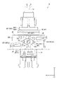
- FIG. 15 is a diagram showing a cross section of the rotary operator 2 along the XZ plane at the position of the contact portion 515 inserted through the guide hole 343 in the -Y direction.
- FIG. 15 is a diagram showing a cross section of the rotary operator 2 taken along line XV-XV shown in FIG.
- the contactor 51 is arranged at the second position. However, when the rotating body 42 rotates in the +D direction in the counterclockwise range, the contactor 51 is pushed out in the +Y direction by the guide surface 473, and at the same time, as shown in FIG. direction inner surface 343A.
- the contactor 51 is pushed out in the +Y direction by the guide surface 483 and simultaneously pressed against the inner surface 343B of the guide hole 343 in the -X direction. be done. Therefore, the contact portion 515 is sandwiched between the guide surface 473 and the inner surface 343B, or sandwiched between the guide surface 483 and the inner surface 343A. In this case, the contactor 51 is difficult to move from the first position to the second position.
- Whether the contactor 51 moves to the second position while being pushed out in the +Y direction by the guide surface 473 or the guide surface 483 depends on the biasing force of the first biasing member 52 and the force of the second biasing member 53 . It is determined by the balance with the urging force. For example, by making the biasing force of the first biasing member 52 lower than the first threshold value and the biasing force of the second biasing member 53 higher than the second threshold value, during rotation of the rotating body 42, that is, rotation
- the rotary operator 2 can be configured so that the movement to the second position does not occur when the knob 43 is applied with a torque capable of rotating the moving body 42 .
- the rotational speed of the rotating body 42 is increased to a predetermined rotational speed or higher.
- the rotary operator 2 can be configured so that the contactor 51 reaches the second position before reaching the restricting surface 472 or the restricting surface 482 if the contactor 51 is not rotated by . In this case, movement of the contactor 51 in the +D direction by the restricting surface 472, that is, rotation of the rotating body 42 in the ⁇ D direction is not restricted. , that is, the rotation of the rotating body 42 in the +D direction is not restricted.
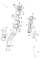
- FIG. 16 and 17 are exploded perspective views showing the operator main body 4 and the operational feeling switching mechanism 6.
- FIG. 16 is an exploded perspective view of the operator main body 4 and the operational feeling switching mechanism 6 as seen from the +Z direction
- FIG. 17 is an exploded perspective view of the operator main body 4 and the operational feel switching mechanism 6 as seen from the ⁇ Z direction.
- 1 is an exploded perspective view;
- the operation feeling switching mechanism 6 switches the operation mode of the state switching mechanism 7 and the operation feeling of the rotary operator 2 according to a switching operation on the state switching mechanism 7 described later.
- the operational feeling is a click feeling
- the operational feeling switching mechanism 6 switches between a state in which a click feeling is produced when the rotating body 42 is rotated and a state in which no click feeling is produced.
- the operational feeling switching mechanism 6 is provided between the cover member 38 and the cylindrical portion 45 of the rotating body 42 in the first placement portion 32 of the housing portion 3 .
- the operational feeling switching mechanism 6 has a click plate 61, a moving base 62 and an urging member 63, as shown in FIGS.
- the click plate 61 is provided in the +Z direction with respect to the cylindrical portion 45 and is moved in the -Z direction to approach the cylindrical portion 45 of the rotating body 42 or in the +Z direction away from the cylindrical portion 45 by the movement base 62 .
- the click plate 61 corresponds to an engaging member and can engage with the cylindrical portion 45 when moved in the -Z direction.
- the click plate 61 has a plate body 611 , a guided portion 612 , an engaging portion 613 and a projecting portion 614 .
- the plate body 611 is formed in a ring shape.
- the plate main body 611 is provided with a circular opening 6111 into which a part of the rotating body main body 44 in the +Z direction is inserted.
- the +Z direction surface of the plate body 611 is provided with two recessed arrangement portions 6112 that are recessed in the ⁇ Z direction.
- the two arrangement portions 6112 are provided at positions sandwiching the center of the click plate 61 when viewed from the +Z direction.
- a biasing member 63 is provided inside each arrangement portion 6112 .
- the guided portions 612 are portions that protrude radially outward from the outer peripheral edge of the plate body 611 , and three guided portions are provided on the plate body 611 .
- Each of the guided portions 612 is arranged in the guide portions 321 to 323 provided in the housing portion 3, thereby restricting the rotation of the click plate 61 about the rotation axis Rx and ⁇ Z Directional movement is guided.
- the engaging portion 613 is a portion protruding radially outward from the outer peripheral edge of the plate body 611 , and three engagement portions 613 are provided on the plate body 611 .
- Each engaging portion 613 engages with an inclined portion 624 of the moving base 62 .
- the projecting portions 614 are provided on two of the three guided portions 612 provided at both ends of the plate body 611 in the +X direction.
- Each protruding portion 614 protrudes in the ⁇ Z direction from the surface of the guided portion 612 in the ⁇ Z direction in a substantially quadrangular truncated pyramid shape. That is, the projecting portion 614 has an inclined surface facing the +Y direction and an inclined surface facing the -Y direction. In other words, each protrusion 614 has an inclined surface facing the +D direction and an inclined surface facing the -D direction.
- the protruding portion 614 fits into the fitting portion 451 when the rotating body 42 rotates, and produces a click feeling.
- the position of the fitting portion 451 on the rotating body 42 and the position of the protruding portion 614 on the click plate 61 are defined so that the click feeling is generated when the rotating body 42 is arranged at the first reference position, for example. It is Since the click plate 61 is movable in the ⁇ Z directions, when the rotating body 42 is further rotated in a state in which the projecting portion 614 is fitted in the fitting portion 451 , the projecting portion 614 moves away from the fitting portion 451 . Separate.
- the moving base 62 is provided so as to be rotatable about the rotation axis Rx of the rotating body 42 .
- the moving base 62 engages with a slide member 72 of the state switching mechanism 7, which will be described later, and moves the click plate 61 in the ⁇ Z directions as the slide member 72 moves in the ⁇ Y directions. That is, the moving base 62 is a moving member that brings the click plate 61 closer to or away from the fitting portion 451 of the rotating body 42 as the slide member 72 slides.
- the moving base 62 has a base body 621, two extending portions 622, a connecting portion 623 and an inclined portion 624, as shown in FIGS.
- the base body 621 is formed in a ring shape.
- the base main body 621 is provided with a circular opening 6211 into which a part of the rotating body main body 44 in the +Z direction is inserted.
- the two extending portions 622 extend radially outward from the periphery of the base body 621 when viewed from the +Z direction and in opposite directions. Specifically, one of the two extensions 622 extends in the +Y direction, and the other extension 622 extends in the -Y direction.
- the connecting portion 623 connects the ends of the extending portions 622 in the -X direction.
- the connecting portion 623 has an engaging portion 6231 that is provided at the end in the ⁇ X direction and engages with the slide member 72 . That is, the operational feeling switching mechanism 6 has an engaging portion 6231 that engages with the slide member 72 .
- the engaging portion 6231 is formed in a cylindrical shape protruding from the connecting portion 623 in the -Z direction.
- the inclined portions 624 are provided at the +X direction end and the ⁇ X direction end of each extending portion 622 . That is, the moving base 62 has four slopes 624 . Each inclined portion 624 is inclined with respect to the circumferential direction around the rotation axis of the moving base 62 . More specifically, the inclined portion 624 is inclined in the +Z direction and in the counterclockwise direction about the rotation axis Rx when viewed from the +Z direction. The inclined portion 624 pushes up the engaging portion 613 and the guided portion 612 in the -X direction in the +Z direction along with the counterclockwise rotation of the moving base 62 when viewed from the +Z direction. It is separated from the cylindrical portion 45 . As a result, even if the rotating body 42 is rotated, the projecting portion 614 does not fit into the fitting portion 451, and the click feeling does not occur.
- the biasing member 63 biases the click plate 61 in the -Z direction.
- the biasing member 63 is provided in the corresponding arrangement portion 6112 and arranged between the cover member 38 and the click plate 61, as shown in FIG. That is, the operational feeling switching mechanism 6 has two biasing members 63 .
- the +Z-direction end of each biasing member 63 contacts the -Z-direction surface of the cover member 38 , and the -Z-direction end contacts the click plate 61 .
- the projecting portion 614 is arranged at a position where it cannot be fitted with the fitting portion 451 in the +Z direction. That is, the click plate 61 is arranged at a position where a click feeling cannot be generated.
- Such rotation of the moving base 62 is implemented by sliding of the slide member 72 with which the moving base 62 engages.
- FIG. 18 is a perspective view showing part of the state switching mechanism 7 and one rotary operator 2. As shown in FIG. More specifically, FIG. 18 is a perspective view showing part of the state switching mechanism 7 and the rotary operator 2 that constitutes the effect adjustment section 157A. 19 is an exploded perspective view showing part of the state switching mechanism 7.
- FIG. The state switching mechanism 7 switches the operation mode and operation feeling of the rotary operator 2 as described above.
- the state switching mechanism 7 includes a slide switch 71 and a slide member 72, as shown in FIGS.
- the slide switch 71 has a slide operator 711 and a holder 712 holding the slide operator 711, as shown in FIGS.
- the slide switch 71 switches the operation mode of the rotary operator 2 according to the position of the slide operator 711 .
- the slide operator 711 is exposed to the microphone adjustment section 12 (see FIG. 1) on the top surface 11A of the housing 11 .
- the slide operator 711 is provided on the holder 712 so as to be slidable in the +Y direction.
- the slide operator 711 can be arranged at three positions along the +Y direction.
- the slide operator 711 has a first switching position, a second switching position that is a position in the +Y direction with respect to the first switching position, and a third switching position that is a position in the +Y direction with respect to the second switching position. can be arranged at one of the switching positions.
- the holder 712 is fixed inside the housing 11 .
- the holder 712 outputs an operation signal corresponding to the position of the slide operator 711 to a control unit (not shown) that controls the audio device 1 to switch the operation mode of the rotary operator 2 .
- the setting of the operation mode according to the arrangement position of the slide operator 711 will be described in detail later.
- the slide member 72 is provided in the housing 11 so as to be slidable according to a slide operation on the slide operator 711 . That is, the slide member 72 slides together with the slide operator 711 in the same direction as the slide operator 711 .
- the slide member 72 has a first slide member 73 , an elastic member 74 , a biasing member 75 and a second slide member 76 .
- the first slide member 73 engages with the slide operator 711 and slides along with the slide operator 711 in the ⁇ Y direction.
- the first slide member 73 has one opening 731 as shown in FIGS. 2, 18 and 19, and also has a holding portion 732 as shown in FIG.
- a slide operator 711 is inserted into the opening 731 from the -Z direction.
- the inner diameter of the opening 731 substantially matches the outer diameter of the slide operator 711 . Therefore, the slide operator 711 is exposed from the opening 731 in the +Z direction.
- the first slide member 73 slides in the same direction as the sliding direction of the slide operator 711 .
- the holding portion 732 holds the elastic member 74 , the biasing member 75 and the second slide member 76 .
- the holding portion 732 , the elastic member 74 , the biasing member 75 and the second slide member 76 are provided according to the number of the rotary operators 2 .
- the holding portion 732 includes a holding portion 732A corresponding to the rotary operator 2 constituting the effect adjusting portion 157A, a holding portion 732B corresponding to the rotary operator 2 constituting the effect adjusting portion 157B, A holding portion 732C corresponding to the rotary operator 2 forming the effect adjustment portion 157C and a holding portion 732D corresponding to the rotary operator 2 forming the effect adjustment portion 157D are included.
- the holding portion 732A has an arrangement portion 733, two clamping pieces 734, two engaging pieces 735, and an opening 736, as shown in FIGS.
- the arrangement portion 733 is a wall along the XY plane.
- the elastic member 74 is fixed to the arrangement portion 733 , and the biasing member 75 and the second slide member 76 are also arranged.
- the two holding pieces 734 are provided at positions facing the arrangement portion 733 in the +Z direction.
- the two clamping pieces 734 clamp the urging member 75 and the second slide member 76 arranged in the arrangement portion 733 between themselves and the arrangement portion 733 .
- the two engaging pieces 735 protrude in the +Z direction from the +X direction end of the placement portion 733 .
- the two engaging pieces 735 restrict the biasing member 75 and the second slide member 76 arranged in the arrangement portion 733 from sliding in the +X direction.
- An engaging portion 6231 of the moving base 62 is arranged between the two engaging pieces 735 .
- the engaging portion 552 of the switching member 55 is inserted into the opening 736 .
- the holding portions 732B, 732C, and 732D have the same configuration as the holding portion 732A, so the description of the holding portions 732B, 732C, and 732D is omitted.
- the elastic member 74 is provided on the +Z direction surface of the placement portion 733, and is a member that fills the gap between the placement portion 733 and the second slide member 76 provided on the placement portion 733. .
- the elastic member 74 prevents the second slide member 76 from unintentionally sliding along the XY plane.
- the biasing member 75 is a member that biases the second slide member 76 toward the first slide member 73, and a leaf spring is employed as the biasing member 75 in this embodiment.
- the biasing member 75 is arranged between the clamping piece 734 and the placement portion 733 and biases the second slide member 76 toward the placement portion 733 .
- An opening 751 along the +Y direction is provided in the center of the biasing member 75 when viewed from the +Z direction, and the insertion portion 761 of the second slide member 76 is inserted into the opening 751 .
- the second slide member 76 is provided on the placement portion 733 of the first slide member 73 so as to be slidable in the ⁇ Y directions, which are the sliding directions of the first slide member 73 .
- the second slide member 76 rotates the switching member 55 of the corresponding rotary operator 2 .
- the second slide member 76 is provided to absorb tolerances of members such as the regulation switching mechanism 5 and the first slide member 73 .
- the second slide member 76 has an insertion portion 761 , a regulation piece 762 , a recessed portion 763 and a through hole 764 .
- the insertion portion 761 protrudes in the +Z direction from approximately the center of the second slide member 76 when viewed from the +Z direction.
- the insertion portion 761 is inserted into the opening 751 of the biasing member 75 .
- Two restricting pieces 762 are provided on the +Z direction surface of the second slide member 76, and the two restricting pieces 762 are separated in the +Y direction. Between the two regulating pieces 762, the biasing member 75 is arranged, and the two clamping pieces 734 are sandwiched in the +Y direction. This defines the slidable range of the second slide member 76 in the +Y direction.
- the concave portion 763 is provided on the +X direction end surface of the second slide member 76 .
- the recessed portion 763 is recessed in the -X direction and is a portion for avoiding the engaging portion 6231 of the moving base 62 that engages with the two engaging pieces 735 .
- the through-hole 764 is an opening provided in the +Y-direction portion of the second slide member 76 .
- the through-hole 764 penetrates the second slide member 76 along the +Z direction.
- the engaging portion 552 of the switching member 55 is inserted into the through-hole 764 .
- the slide operator 711 is arranged at one of the first switching position, the second switching position, and the third switching position by sliding in the ⁇ Y directions. Further, since the slide member 72 is engaged with the slide operator 711, the slide member 72 slides along with the slide operator 711 in the ⁇ Y direction.
- FIG. 20 is a plan view showing the state switching mechanism 7 with the slide operator 711 arranged at the first switching position.
- a dashed line L1 indicates the position of the end in the -Y direction of the slide operator 711 arranged at the first switching position.
- a dashed-dotted line L2 indicates the position of the end portion in the -Y direction of the slide operator 711 placed at the second switching position, and a dashed-dotted line L3 indicates the -Y direction of the slide operator 711 placed at the third switching position. indicates the position of the end of the As shown in FIG.
- the holder 712 switches the operating mode of the rotating operator 2, and thus the operating mode of the acoustic device 1, to the first position. 1 mode is output to the control unit.
- the control unit that receives the switching signal to the first mode switches the operation mode of the rotary operator 2 to the first mode.
- the slide member 72 is arranged most in the ⁇ Y direction in the movable range of the slide member 72 .
- the click plate 61 of the operational feeling switching mechanism 6 does not fit the projecting portion 614 into the fitting portion 451 even when the rotating body 42 is rotated by the moving base 62 engaged with the slide member 72 . placed in position.
- the moving base 62 arranges the click plate 61 at a position where a click feeling does not occur even when the rotating body 42 is rotated.
- the holding member 54 and the contactor 51 are biased by the third biasing member 56 and arranged at a position separated from the rotating body 42 in the +Y direction by the switching member 55 that engages with the slide member 72. .
- the first mode is an operation mode in which the effect amount of one effect is set using the entire rotatable range of the rotatable body 42 including the reference position. That is, in the first mode, the rotation limit of the rotating body 42 in the -D direction is set to the minimum value, the rotation limit of the rotating body 42 in the +D direction is set to the maximum value, and based on the rotation angle of the rotating body 42 This mode sets the effect amount of one effect. In the first mode, no click feeling is generated when the rotating body 42 is rotated.
- FIG. 21 is a plan view showing the state switching mechanism 7 with the slide operator 711 arranged at the second switching position.
- the dashed-dotted lines L1 to L3 in FIG. 21 are the same as the dashed-dotted lines L1 to L3 shown in FIG.
- the holder 712 switches the operation mode of the rotary operator 2, and thus the operation mode of the acoustic device 1, to the second position.
- An operation signal for switching between the two modes is output to the control unit.
- the control unit that receives the signal for switching to the second mode switches the operation mode of the rotary operator 2 to the second mode.
- the slide member 72 is arranged substantially in the center of the movable range of the slide member 72 .
- the click plate 61 of the operational feeling switching mechanism 6 is arranged at a position where the protruding portion 614 can be fitted into the fitting portion 451 by the moving base 62 . That is, the click plate 61 is arranged by the moving base 62 at a position where a click feeling is generated when the rotating body 42 is rotated.
- the holding member 54 and the contactor 51 are arranged at a position spaced apart from the rotating body 42 in the +Y direction by the switching member 55, as in the case where the slide operator 711 is arranged at the first switching position.
- the contact portion 515 is separated from the rotating body 42 , the rotation of the rotating body 42 straddling the reference position is not restricted by the contactor 51 .
- the effect amount of the first effect is adjusted according to the rotation angle of the rotating body 42 in the +D direction from the reference position. is set, and when the rotating body 42 is rotated in the -D direction from the reference position, the effect amount of the second effect is set according to the rotation angle of the rotating body 42 in the -D direction from the reference position. be.
- a click feeling is generated when the rotating body 42 is rotated.
- FIG. 22 is a plan view showing the state switching mechanism 7 with the slide operator 711 arranged at the third switching position.
- the dashed-dotted lines L1 to L3 in FIG. 22 are the same as the dashed-dotted lines L1 to L3 shown in FIG.
- the holder 712 switches the operation mode of the rotary operator 2, and thus the operation mode of the acoustic device 1, to the above-described operation mode.
- An operation signal for switching to the third mode is output to the control unit.
- the slide member 72 When the slide operator 711 is arranged at the third switching position, the slide member 72 is arranged most in the +Y direction in the movable range of the slide member 72 .
- the clicking plate 61 of the operation feeling switching mechanism 6 has the projecting portion 614 fitted into the fitting portion 451 by the moving base 62, as in the case where the slide operator 711 is arranged at the second switching position. placed where possible. That is, the click plate 61 is arranged by the moving base 62 at a position where a click feeling is generated when the rotating body 42 is rotated.
- the slide member 72 when the slide member 72 is arranged at the third switching position, the biasing of the holding member 54 in the +Y direction by the switching member 55 rotated clockwise when viewed from the +Z direction by the slide member 72 is released.
- the holding member 54 is urged in the -Y direction by the second urging member 53, and the contactor 51 is thus urged in a direction approaching the rotation axis Rx.
- the contact portion 515 comes into contact with the rotating body 42 . Since the contact portion 515 moves along the movement paths RT1 and RT2 as the rotating body 42 rotates, the rotation of the rotating body 42 straddling the reference position is regulated.
- the effect amount of the first effect is set according to the rotation angle of the rotating body 42 from the reference position in the +D direction.
- the effect amount of the second effect is set according to the rotation angle of the rotating body 42 in the D direction. Therefore, when the effect amount of one of the first effect and the second effect is adjusted, erroneous adjustment of the effect amount of the other effect is suppressed.
- each rotary operator 2 constituting the effect adjustment units 157A to 157D is performed. Not only can the mode be switched, but also the operation feeling of each rotary operator 2 and the restricted state of each rotary operator 2 can be switched at the same time.
- the acoustic device 1 includes a rotary operator 2 as an operator, a state switching mechanism 7 , and an operational feeling switching mechanism 6 .
- the state switching mechanism 7 switches the operation mode of the rotary operator 2 according to a switching operation on the state switching mechanism 7 .
- the operation feeling switching mechanism 6 switches the operation mode of the state switching mechanism 7 and the operation feeling of the rotary operator 2 according to the switching operation on the state switching mechanism 7 .
- the operation mode of the rotary operator 2 is switched and the operational feeling of the rotary operator 2 is switched by the switching operation on the state switching mechanism 7 .
- the operation mode and operational feeling of the rotary operator 2 can be switched by a single switching operation. Therefore, the usability of the audio device 1 can be enhanced.
- a plurality of rotary operators 2 are provided.
- the operational feeling switching mechanism 6 is provided for each of the plurality of rotary operators 2 .
- the state switching mechanism 7 switches operation modes of the plurality of rotary operators 2 and operates the plurality of operational feeling switching mechanisms 6 . According to such a configuration, it is possible to switch the operation mode and operation feeling of each of the plurality of rotary operators 2 with a single switching operation. Therefore, the usability of the audio device 1 can be enhanced.
- the operation feeling switching mechanism 6 switches the operation feeling between a state in which a click feeling is generated when the rotary operator 2 is operated, and a state in which a click feeling is not generated.
- the usability of the rotary operator 2 can be enhanced, and the usability of the audio device 1 can be enhanced.
- the state switching mechanism 7 has a slide switch 71 and a slide member 72 .
- the slide switch 71 includes a slide operator 711 and switches the operation mode of the rotary operator 2 according to the position of the slide operator 711 .
- the slide member 72 is slidable together with the slide operator 711 .
- the operational feeling switching mechanism 6 has an engaging portion 7231 that engages with the slide member 72 . According to such a configuration, by sliding the slide operator 711, the operation mode of the rotary operator 2 is switched by the slide switch 71, and the operational feeling is switched by engaging with the slide member 72 that slides together with the slide operator 711. Switching of the operation feeling of the rotary operator 2 by the mechanism 6 can be implemented. Therefore, the usability of the audio device 1 can be enhanced.
- the rotary operator 2 has a rotating body 42 that rotates about the rotating shaft Rx.
- the operational feeling switching mechanism 6 has a click plate 61 and a moving base 62 .
- the click plate 61 corresponds to an engaging member and can be engaged with the rotating body 42 .
- the moving base 62 corresponds to a moving member, has an engaging portion 6231 , and brings the click plate 61 closer to or away from the cylindrical portion 45 of the rotating body 42 as the slide member 72 slides.
- the click plate 61 has a projecting portion 614, and the rotating body 42 has a fitting portion 451 into which the projecting portion 614 can be fitted.
- the projection 614 can be fitted to the fitting portion 451 at a position where the projection 614 can be fitted to the fitting portion 451 .
- the arrangement position of the click plate 61 can be switched to a position where it cannot be fitted.
- the click plate 61 is arranged at a position where the projecting portion 614 can fit into the fitting portion 451, the projecting portion 614 fits into the fitting portion 451 as the rotating body 42 rotates.
- a click feeling can be generated when the rotating member 42 is rotated, that is, when the rotary operator 2 is operated. Therefore, it is possible to switch between the case where a click feeling is generated and the case where a click feeling is not generated when the rotary operator 2 is operated.
- the acoustic device 1 includes a contactor 51 and a switching member 55 .
- the contactor 51 comes into contact with the rotary operator 2 and restricts the rotation of the rotating body 42 .
- the switching member 55 switches between a position where the contactor 51 can contact the rotating body 42 and a position where the contactor 51 can contact the rotating body 42 according to the switching operation of the state switching mechanism 7 , that is, the sliding operation of the slide operator 711 .
- the position of the contactor 51 is switched between the position where the contactor 51 is not.
- the slide member 72 includes a first slide member 73 , a biasing member 75 and a second slide member 76 .
- the first slide member 73 engages with the slide operator 711 .
- the second slide member 76 is provided on the first slide member 73 so as to be slidable in the ⁇ Y directions, which are the sliding directions of the first slide member 73 .
- the biasing member 75 biases the second slide member 76 toward the first slide member 73 .
- the switching member 55 is a lever member that engages with the second slide member 76 and rotates as the second slide member 76 slides to switch the position of the contactor 51 .
- the second slide member 76 engaged with the switching member 55 which is a lever member, slides with respect to the first slide member 73, thereby changing the position of the switching member 55 and the slide member due to tolerances or the like. It is possible to suppress the position of 72 from deviating from an appropriate position. In particular, the tolerance tends to accumulate and increase as the number of parts increases. positional error of the slide member 72 increases.
- the tolerance of each member such as the regulation switching mechanism 5 including the switching member 55 and the state switching mechanism 7 including the slide member 72 is absorbed. can. Since the biasing member 75 biases the second slide member 76 toward the first slide member 73, the second slide member 76 can be maintained at an appropriate position.
- the acoustic device according to the present embodiment has a configuration similar to that of the acoustic device 1 according to the first embodiment, but differs in the configuration of the path forming portion provided on the rotating body of the rotary operator. is different from the acoustic device 1 according to
- the same or substantially the same parts as those already described are given the same reference numerals, and the description thereof will be omitted.
- FIG. 23 is a schematic diagram showing the cylindrical portion 49 of the manipulator main body 4A of the rotary manipulator 2A provided in the acoustic device according to this embodiment.
- FIG. 23 shows the contact portion 515 of the contactor 51 that moves relative to the operator main body 4A along the cylindrical portion 49, and also shows the positions PT1 to PT8 where the contact portion 515 can be arranged. showing.
- the acoustic device according to the present embodiment has the same configuration and functions as the acoustic device 1 according to the first embodiment, except that a rotary operator 2A shown in FIG. 23 is provided instead of the rotary operator 2.
- FIG. 23 shows the same configuration and functions as the acoustic device 1 according to the first embodiment, except that a rotary operator 2A shown in FIG. 23 is provided instead of the rotary operator 2.
- the rotary operator 2A is an operator that is rotated about the rotation axis Rx by the user.
- the rotary operator 2A constitutes, for example, effect adjustment sections 157A to 157D.
- the rotary operator 2A has the same configuration and functions as the rotary operator 2 except that it has an operator main body 4A instead of the operator main body 4. As shown in FIG.
- the manipulator main body 4A is a rotary volume that is rotated by the user and outputs a rotation angle with respect to the reference position, like the manipulator main body 4 according to the first embodiment.
- the operator main body 4A includes the above-described pedestal portion 41 and a rotating body 42A.
- 42 A of rotation bodies have the above-described knob 43 and 44 A of rotation body main bodies.
- the rotating body main body 44A has the same configuration as the rotating body main body 44 except that it has a cylindrical portion 49 instead of the cylindrical portion 45 .
- the cylindrical portion 49 is formed in a cylindrical shape around the rotation axis Rx of the rotating body 42A in the rotating body main body 44A.
- Path forming portions 491 and 493 and restricting portions 492 and 494 are provided on an outer peripheral surface 49A of the cylindrical portion 49 . That is, the cylindrical portion 49 has path forming portions 491 and 493 and restricting portions 492 and 494 projecting radially outward from the outer peripheral surface 49A about the rotation axis Rx.
- the contact portion 515 of the contactor 51 contacts the rotating body 42A. Movement paths RT3 and RT4 that move relative to each other are formed.
- the path forming portion 491 forms a movement path RT3 of the contact portion 515 when the rotating body 42A is rotated in the counterclockwise range.
- the movement path RT3 is inclined with respect to the circumferential direction about the rotation axis Rx. That is, the outer peripheral surface 49A of the rotating body 42A is provided with a movement path RT3 that is inclined with respect to the circumferential direction about the rotation axis Rx.
- the restricting portion 492 moves in the -D direction when the rotating body 42A arranged in the counterclockwise side range rotates in the clockwise +D direction and reaches the reference position.
- the contact portion 515 comes into contact and restricts the movement of the contact portion 515 in the -D direction and the rotation of the rotating body 42A in the +D direction.
- the path forming part 493 forms a movement path RT4 of the contact part 515 when the rotating body 42A arranged in the clockwise range is rotated.
- the movement path RT4 is inclined with respect to the circumferential direction about the rotation axis Rx. That is, the outer peripheral surface 49A of the rotating body 42A is provided with a movement path RT4 that is inclined with respect to the circumferential direction about the rotation axis Rx.
- the restricting portion 494 contacts the contact portion 515 moving in the +D direction when the rotating body 42A arranged in the clockwise range is rotated in the -D direction and reaches the reference position. This restricts the movement of the contact portion 515 in the +D direction, and thus the rotation of the rotating body 42A in the -D direction.
- the path forming portion 493 forms a movement path RT4 of the contact portion 515 when the rotating body 42A is rotated in the clockwise range.
- the path forming portion 491 and the path forming portion 493 are provided on the outer peripheral surface 49A symmetrically about the position PT1.
- the restricting portion 492 and the restricting portion 494 are provided on the outer peripheral surface 49A symmetrically about the position PT1.
- the path forming portion 491 is inclined with respect to the +D direction and the +Z direction so as to be positioned in the +Z direction as it goes in the +D direction.
- the +Z direction surface of the path forming portion 491 is the first path until the contact portion 515 arranged at the position PT1 in the counterclockwise range of the movement path RT3 moves in the +D direction and reaches the second path RT32.
- the ⁇ Z direction surface of the path forming portion 491 is a portion of the second path RT32 until the contact portion 515 reaches the movement limit in the +D direction in the counterclockwise range of the movement path RT3 and reaches the restricting portion 492. form a part.
- the length of the first route RT31 in the +D direction is substantially the same as the length of the second route RT32 in the +D direction.
- the +Z direction surface forming the first route RT31 in the route forming portion 491 and the ⁇ Z direction surface forming a part of the second route RT32 in the route forming portion 491 each have the rotation axis Rx. It is inclined with respect to the circumferential direction of the center.
- the contact portion 515 moves along the first route RT31 and reaches, for example, the position PT2.
- the contact portion 515 In a state where the contact portion 515 is positioned on the first path RT31, when the rotating body 42A is rotated in the +D direction, the contact portion 515 relatively moves along the first path RT31 in the -D direction. . In this case, since the contact portion 515 does not contact the restricting portion 492, the rotation of the rotating body 42A across the reference position is not restricted.
- the contact portion 515 and the path forming portion 491 are separated from each other,
- the contact portion 515 reaches the second route RT32 connecting the movement limit in the +D direction and the position PT5 (the first position in the counterclockwise range).
- the position of the contact portion 515 in the +Z direction matches the position of the contact portion 515 in the +Z direction when the contactor 51 is arranged at the position PT1.
- the contact portion 515 when the contact portion 515 is separated from the path forming portion 491 and the rotating body 42A is rotated to the rotation limit in the -D direction, the position of the contact portion 515 in the +Z direction changes. Without moving, it is moved along the second route RT32 to the movement limit in the +D direction.
- the +D-direction end of the path forming portion 491 is located in the +Z-direction relative to the +Z-direction end of the contact portion 515 when the contactor 51 is arranged at the position PT1.
- the contact portion 515 is in contact with the surface of the path forming portion 491 in the -Z direction, as indicated by position PT3. Contact. Then, when the rotating body 42A is further rotated in the +D direction, the contact portion 515 reaches the position PT4.
- the contact portion 515 In a state in which the contact portion 515 is arranged on the second route RT32, when the rotating body 42A is rotated in the +D direction and reaches the reference position, the contact portion 515 is provided on the extension line of the second route RT32. reaches a position PT5 where it contacts the regulating portion 492.
- the position of the contactor 51 when the contact portion 515 is arranged at the position PT5 corresponds to the first position in the counterclockwise range. Since the movement in the -D direction of the contact portion 515 that has reached the position PT5 is restricted by the restriction portion 492, the rotation of the rotating body 42A in the +D direction is restricted.
- the rotation of the rotating body 42A in the +D direction from the reference position is restricted by the contactor 51 being at the first position in the counterclockwise range.
- the contactor 51 With the contactor 51 positioned at the first position, when the user releases the finger from the knob 43 to reduce the rotational force of the rotating body 42A in the +D direction, the first biasing member 52 moves in the +Z direction. , the contact portion 515 returns to the position PT1.
- the position of the contactor 51 when the contact portion 515 is arranged at the position PT1 corresponds to the second position. This permits the relative movement of the contact portion 515 in the -D direction, and thus the rotation of the rotating body 42A straddling the reference position in the +D direction.
- the path forming part 493 is inclined with respect to the -D direction and the -Z direction so that it is positioned in the -Z direction as it goes in the -D direction.
- the -Z direction surface of the path forming portion 493 is the first contact portion 515 arranged at the position PT1 in the clockwise range of the movement path RT4 to move in the -D direction and reach the second path RT42. 1 route RT41 is formed.
- the +Z direction surface of the path forming portion 491 is part of the second path RT42 until the contact portion 515 reaches the movement limit in the ⁇ D direction in the clockwise range of the movement path RT4 and reaches the restricting portion 494.
- the length of the first route RT41 in the +D direction is substantially the same as the length of the second route RT42 in the -D direction.
- the ⁇ Z direction surface forming the first route RT41 in the route forming portion 493 and the +Z direction surface forming part of the second route RT42 in the route forming portion 493 each have the rotation axis Rx. It is inclined with respect to the circumferential direction of the center.
- the contact portion 515 moves along the first path RT41 from the position PT1 and reaches, for example, the position PT6.
- the contact portion 515 relatively moves in the +D direction along the first path RT41. .
- the contact portion 515 does not contact the restricting portion 494, the rotation of the rotating body 42A across the reference position is not restricted.
- the contact portion 515 and the path forming portion 493 are separated from each other, and the contact portion 515 reaches a second route RT42 connecting the limit of movement in the -D direction and the position PT9 (the first position in the clockwise range).
- the position of the contact portion 515 in the +Z direction matches the position of the contact portion 515 in the +Z direction when the contactor 51 is arranged at the position PT1.
- the rotating body 42A is rotated to the rotation limit in the +D direction while the contact portion 515 is separated from the path forming portion 493, the position of the contact portion 515 in the +Z direction does not change. without being moved, it is moved along the second route RT42 to the movement limit in the -D direction.
- the ⁇ D direction end of the path forming portion 493 is positioned in the ⁇ Z direction more than the ⁇ Z direction end of the contact portion 515 when the contactor 51 is arranged at the position PT1.
- the contact portion 515 With the contact portion 515 arranged on the second route RT42, when the rotating body 42A is rotated in the -D direction and reaches the reference position, the contact portion 515 is positioned on the extension line of the second route RT42. It reaches a position PT9 where it contacts with the regulating portion 494 provided.
- the position of the contactor 51 when the contact portion 515 is arranged at the position PT9 corresponds to the first position in the clockwise range. Since the movement of the contact portion 515 reaching the position PT9 in the +D direction is restricted by the restriction portion 494, the rotation of the rotating body 42A in the -D direction is restricted.
- the rotation of the rotating body 42A in the -D direction from the reference position is restricted by the contactor 51 being at the first position in the clockwise range.
- the first biasing member 52 moves to -
- the biasing force in the Z direction returns the contact portion 515 to the position PT1.
- the position of the contactor 51 when the contact portion 515 is arranged at the position PT1 corresponds to the second position. This permits the relative movement of the contact portion 515 in the +D direction, and thus the rotation of the rotating body 42A across the reference position in the -D direction.
- the rotating body 42A is provided with the movement paths RT3 and RT4 for moving the contactor 51 in the direction along the rotating axis Rx when the rotating body 42A is rotated about the rotating axis Rx. It has a cylindrical cam structure.
- the path forming portion 491 forming the second route RT32 and the route forming portion 493 forming the second route RT42 do not exist near the first position.
- contactor 51 can move to the second position.
- the acoustic device according to the present embodiment described above, it is possible to achieve the same effects as the acoustic device 1 according to the first embodiment.
- FIG. 24 is a perspective view showing a contactor 51A and a first biasing member 52A, which are modifications of the contactor 51 and the first biasing member 52.
- the first biasing member 52 is one compression coil spring, and the contact 51 is biased by the first biasing member 52 .
- the configuration is not limited to this, and the first biasing member 52 has a compression coil spring 52A1 provided in the +Z direction and a compression coil spring 52A2 provided in the -Z direction, as shown in FIG. 24, for example.
- a contactor 51A shown in FIG. 24 may be adopted.
- the contactor 51A includes a contactor main body 511A, a contact portion 515A that protrudes from the contactor main body 51A1 in the -Y direction and contacts the rotating body 42, and a contactor main body 51A1 that protrudes in the +Y direction and is inserted into the guide portion 344. and a projecting portion 516A.
- the contact main body 511A has a protruding portion 512A that protrudes in the +Z direction and is inserted into the compression coil spring 52A1, and a protruding portion 513A that protrudes in the -Z direction and is inserted into the compression coil spring 52A2.
- the contacting portion 515A is moved to the concave portion 46 by the biasing force of the first biasing member 52A. can be biased to be positioned at the bottom 461 or position PT1.
- the rotating body 42 has the path forming portions 47 and 48 .
- the rotating body 42A has the path forming portions 491 and 493 and the restricting portions 492 and 494.
- the configuration is not limited to this, and the rotating body 42 may be configured to have one of the path forming portions 47 and 48 .
- the restricting portion 481 may be provided separately.
- the rotating body 42A may have one of the path forming portion 491 and the regulating portion 492 and the path forming portion 493 and the regulating portion 494 .
- the restricting portion 471 has the guide surface 473 and the restricting portion 481 has the guide surface 483 .
- the restricting portions 471 and 481 may not have the guide surfaces 473 and 483 .
- the rotary operator 2, 2A is provided with the first biasing member 52 that biases the contactor 51 in the direction from the first position to the second position.
- the first biasing member 52 that biases the contactor 51 in the direction from the first position to the second position.
- the first biasing members 52, 52A may be omitted.
- the first biasing members 52 and 52A may not be composed of compression coil springs, and may be composed of other members such as magnets.
- the route forming portion 47 forming the movement route RT1 and the route forming portion 48 forming the movement route RT2 project radially outward from the outer peripheral surface 45A about the rotation axis Rx. I thought I was there.
- the path forming portion 491 that forms the movement path RT3, the path forming portion 493 that forms the movement path RT4, and the restricting portions 492 and 494 are radially outwardly centered on the rotation axis Rx. It is assumed that it protrudes from the outer peripheral surface 49A.
- the movement path along which the contactor 51 moves is not limited to this, and may be formed by a groove provided on the outer peripheral surface of the rotating body.
- the first biasing member 52 biases the contactor 51 in the +Z direction and -Z direction along the rotation axis Rx.
- the direction of biasing by the first biasing member 52 may not necessarily be the direction along the rotation axis Rx. That is, if the contactor 51 in contact with the restricting portions 471, 481, 492, 494 can be returned to the second position, the contactor 51 is biased by the first biasing members 52, 52A in other directions. It can be a direction.
- the second route RT12 is formed longer in the +D direction than the first route RT11, and the second route RT22 is formed longer in the -D direction than the first route RT21.
- the first route RT11 may be formed longer in the +D direction than the second route RT12, and the first route RT21 may be formed longer in the -D direction than the second route RT22.
- the length in the +D direction of the first route RT11 is substantially the same as the length in the +D direction of the second route RT12.
- the length in the -D direction of the first route RT21 may be substantially the same as the length in the -D direction of the second route RT22.
- the rotary operator 2, 2A is provided with the second biasing member 53 that biases the contactor 51 in the direction of approaching the rotation axis Rx of the rotating body .
- the second biasing member 53 can be omitted.
- the contactor 51 does not necessarily need to be in contact with the outer peripheral surfaces 45A, 49A of the rotating bodies 42, 42A.
- the rotary operator 2 as an operator is assumed to be an operator that can rotate about the rotation axis Rx.
- the manipulator in the present disclosure may be a manipulator that can move straight.
- the rotation axis Rx may not be a rotation axis along the +Z direction, and may be, for example, a rotation axis along the +X direction or a rotation axis along the +Y direction.
- the acoustic device has a plurality of rotary operators 2, and the operation feeling switching mechanism 6 is provided according to the rotary operators 2.
- the state switching mechanism 7 operates a plurality of operational feeling switching mechanisms 6 .
- the audio device is not limited to this, and may be provided with one rotary operator. Further, even when a plurality of rotary operators 2 are provided, the state switching mechanism 7 switches the operation mode of at least one rotary operator 2 among the plurality of rotary operators 2, and performs at least one rotary operation.
- the operation feeling switching mechanism 6 provided according to the element 2 may be operated.
- the operation feeling switching mechanism 6 switches between a state in which a click feeling is generated when the rotary operator 2 is operated, and a state in which a click feeling is not generated.
- the operation feeling switching mechanism is not limited to this, and may adjust the rotational resistance of the rotary operator 2 and switch between a state of high rotational resistance and a state of low rotational resistance.
- the operational feeling switching mechanism may switch between a state in which movement resistance of the manipulator is high and a state in which movement resistance is low. That is, as long as the operational feeling switching mechanism of the present disclosure can change the user's operational feeling when operating the manipulator, the content of the operational feeling does not matter.
- the state switching mechanism 7 includes the slide switch 71 including the slide operator 711 and the slide member 72 that can slide together with the slide operator 711 .
- the configuration of the state switching mechanism 7 is not limited to the above.
- the slide switch 71 instead of the slide switch 71, a sensor for detecting the position of the slide member 72 may be provided, and the operation mode may be switched according to the position of the slide member 72.
- the slide operator 711 can be arranged at one of the first switching position, the second switching position, and the third switching position.
- the present invention is not limited to this, as long as the slide operator 711 can be arranged at two or more positions.
- the moving base 62 as the moving member engages with the slide member 72 and rotates about the rotation axis Rx to move the click plate 61 as the engaging member.
- the moving base 62 does not necessarily have to rotate.
- the movement base 62 may move linearly to move the click plate 61 , or the slide member 72 may move the click plate 61 .
- the configuration is not limited to the configuration in which the click plate 61 has the projecting portion 614 and the rotating body 42 has the fitting portion 451.
- the click plate 61 may have the fitting portion and the rotating body 42 may have the projecting portion. good.
- the operational feeling switching mechanism 6 does not necessarily have to include the biasing member 63 .
- the acoustic device includes the regulation switching mechanism 5 having the contacts 51 and 51A and the switching member 55.
- the regulation switching mechanism 5 may be omitted.
- the restriction of the rotating body 42 by the restriction switching mechanism may be based on another configuration.
- the slide member 72 has the first slide member 73, the biasing member 75, and the second slide member 76, and the switching member 55 is rotatably supported by the housing section 3 and contacts. It is assumed that it is a lever member for switching the positions of the elements 51 and 51A.
- the present invention is not limited to this, and the biasing member 75 and the second slide member 76 may be omitted.
- the regulation switching mechanism 5 and the operational feeling switching mechanism 6 may be engaged with the first slide member 73 , and the first sliding member 73 may operate the regulation switching mechanism 5 and the operational feeling switching mechanism 6 .
- the switching member 55 is not limited to the lever member, and may be arranged at a position where the contactors 51 and 51A approach or separate from the rotating body 42 by other configurations.
- the rotary operators 2 and 2A, the operational feeling switching mechanism 6, and the state switching mechanism 7 are employed in the audio device, which is a mixer.
- the audio device of the present disclosure is not limited to this, and may be another audio device such as a DJ controller.
- a sound device comprises an operator, a state switching mechanism for switching an operation mode of the operator according to the switching operation, switching the operation mode by the state switching mechanism according to the switching operation, and switching the operation mode according to the switching operation.
- an operation feeling switching mechanism for switching the operation feeling of the manipulator. According to such a configuration, the operation mode of the manipulator is switched by the switching operation on the state switching mechanism, and the operation feeling of the manipulator is switched. According to this, it is possible to switch the operation mode and the operation feeling of the operator with a single switching operation. Therefore, the usability of the audio device can be enhanced.
- the operational feeling switching mechanism is provided for each of the plurality of operators, and the state switching mechanism includes a plurality of A plurality of the operation feeling switching mechanisms may be operated while switching the operation mode of the operator. According to such a configuration, it is possible to switch the operation mode and operational feeling of each of the plurality of operators with a single switching operation. Therefore, the usability of the audio device can be enhanced.
- the operation feeling switching mechanism has a state in which a click feeling is generated when the manipulator is operated, and a state in which the click feeling is not generated as the operation feeling. You can switch between states. According to such a configuration, it is possible to enhance the usability of the operator, thereby enhancing the usability of the audio device.
- the state switching mechanism includes a slide operator, and a slide switch that switches the operation mode according to the position of the slide operator. and a slide member slidable together with the slide operator, and the operation feeling switching mechanism may have an engaging portion that engages with the slide member.
- the operation mode of the operator is switched by the slide switch, and the operator is operated by the operation feeling switching mechanism that engages with the slide member that slides together with the slide operator. Switching of feeling can be implemented. Therefore, the usability of the audio device can be enhanced.
- the operator is a rotary operator having a rotating body that rotates about a rotating shaft, and the operation feeling switching mechanism is engaged with the rotating body. and a moving member having the engaging portion and moving the engaging member closer to or away from the rotating body as the sliding member slides, wherein the engaging member and one of the rotating bodies may have a projecting portion, and the other of the engaging member and the rotating body may have a fitting portion into which the projecting portion can be fitted.
- the slide operator by operating the slide operator to slide the slide member, the position where the projecting portion can be fitted to the fitting portion and the position where the projecting portion cannot be fitted to the fitting portion are controlled.
- the arrangement position of the engaging member can be switched between and.
- the engaging member When the engaging member is arranged at a position where the protrusion can be fitted into the fitting portion, the protrusion fits into the fitting portion as the rotating body rotates, thereby It is possible to generate a click feeling when rotating, that is, when operating the manipulator. Therefore, it is possible to switch between the case where a click feeling is generated and the case where a click feeling is not generated when the manipulator is operated.
- a switching member may be provided for switching the position of the contact between a position where the contact is possible and a position where the contact is not allowed to contact the rotating body.
- the slide member includes a first slide member that engages with the slide operator, and the first slide member that is slidable along the slide direction of the first slide member. a second slide member provided on a member; and a biasing member biasing the second slide member toward the first slide member, wherein the switching member is engaged with the second slide member; It may be a lever member that rotates with the sliding movement of the second slide member to switch the position of the contactor. According to such a configuration, the second slide member engaged with the switching member, which is a lever member, slides with respect to the first slide member, so that the position of the switching member and the position of the slide member are appropriate due to tolerances and the like.
- the tolerance tends to accumulate and increase as the number of parts increases. positional error increases.
- the tolerance of each member such as the switching member and the slide member can be absorbed. Since the biasing member biases the second slide member toward the first slide member, the second slide member can be maintained at an appropriate position.
Landscapes
- Physics & Mathematics (AREA)
- Engineering & Computer Science (AREA)
- Acoustics & Sound (AREA)
- Multimedia (AREA)
- General Physics & Mathematics (AREA)
- Automation & Control Theory (AREA)
- Signal Processing (AREA)
- Rotary Switch, Piano Key Switch, And Lever Switch (AREA)
Priority Applications (3)
| Application Number | Priority Date | Filing Date | Title |
|---|---|---|---|
| JP2023504932A JP7649842B2 (ja) | 2021-03-09 | 2021-03-09 | 音響装置 |
| PCT/JP2021/009390 WO2022190223A1 (ja) | 2021-03-09 | 2021-03-09 | 音響装置 |
| US18/549,486 US20240304401A1 (en) | 2021-03-09 | 2021-03-09 | Sound device |
Applications Claiming Priority (1)
| Application Number | Priority Date | Filing Date | Title |
|---|---|---|---|
| PCT/JP2021/009390 WO2022190223A1 (ja) | 2021-03-09 | 2021-03-09 | 音響装置 |
Publications (1)
| Publication Number | Publication Date |
|---|---|
| WO2022190223A1 true WO2022190223A1 (ja) | 2022-09-15 |
Family
ID=83226387
Family Applications (1)
| Application Number | Title | Priority Date | Filing Date |
|---|---|---|---|
| PCT/JP2021/009390 Ceased WO2022190223A1 (ja) | 2021-03-09 | 2021-03-09 | 音響装置 |
Country Status (3)
| Country | Link |
|---|---|
| US (1) | US20240304401A1 (https=) |
| JP (1) | JP7649842B2 (https=) |
| WO (1) | WO2022190223A1 (https=) |
Citations (5)
| Publication number | Priority date | Publication date | Assignee | Title |
|---|---|---|---|---|
| JPH1197218A (ja) * | 1997-09-17 | 1999-04-09 | Roland Corp | パラメータ値操作装置 |
| JP2015075912A (ja) * | 2013-10-09 | 2015-04-20 | ソニー株式会社 | 操作機構および撮像装置 |
| JP2017045544A (ja) * | 2015-08-24 | 2017-03-02 | キヤノン株式会社 | 電子機器 |
| JP2017111342A (ja) * | 2015-12-17 | 2017-06-22 | キヤノン株式会社 | 電子機器 |
| JP2020101724A (ja) * | 2018-12-25 | 2020-07-02 | キヤノン株式会社 | 電子機器 |
Family Cites Families (1)
| Publication number | Priority date | Publication date | Assignee | Title |
|---|---|---|---|---|
| JPH1091148A (ja) * | 1996-09-18 | 1998-04-10 | Roland Corp | 電子楽器の鍵盤装置 |
-
2021
- 2021-03-09 US US18/549,486 patent/US20240304401A1/en active Pending
- 2021-03-09 JP JP2023504932A patent/JP7649842B2/ja active Active
- 2021-03-09 WO PCT/JP2021/009390 patent/WO2022190223A1/ja not_active Ceased
Patent Citations (5)
| Publication number | Priority date | Publication date | Assignee | Title |
|---|---|---|---|---|
| JPH1197218A (ja) * | 1997-09-17 | 1999-04-09 | Roland Corp | パラメータ値操作装置 |
| JP2015075912A (ja) * | 2013-10-09 | 2015-04-20 | ソニー株式会社 | 操作機構および撮像装置 |
| JP2017045544A (ja) * | 2015-08-24 | 2017-03-02 | キヤノン株式会社 | 電子機器 |
| JP2017111342A (ja) * | 2015-12-17 | 2017-06-22 | キヤノン株式会社 | 電子機器 |
| JP2020101724A (ja) * | 2018-12-25 | 2020-07-02 | キヤノン株式会社 | 電子機器 |
Also Published As
| Publication number | Publication date |
|---|---|
| JP7649842B2 (ja) | 2025-03-21 |
| JPWO2022190223A1 (https=) | 2022-09-15 |
| US20240304401A1 (en) | 2024-09-12 |
Similar Documents
| Publication | Publication Date | Title |
|---|---|---|
| US7507918B2 (en) | Multidirectional input apparatus and electronic device | |
| EP2016680B1 (en) | Sliding tilt unit and mobile device using the same | |
| JP7660172B2 (ja) | 入力装置、ゲームコントローラ、情報処理装置 | |
| KR101149805B1 (ko) | 다방향 입력장치 | |
| JP6718970B2 (ja) | ヘッドホン | |
| JP7261880B2 (ja) | 音響装置 | |
| JP2004308872A (ja) | 開閉装置及びこれを用いた電子機器 | |
| JP2004150575A (ja) | 開閉装置 | |
| JP2019180393A (ja) | たばこ加熱器用開閉機構 | |
| JP6336760B2 (ja) | 多方向入力装置 | |
| JP2012238999A (ja) | 電子機器 | |
| WO2022190223A1 (ja) | 音響装置 | |
| WO2022190222A1 (ja) | 回転操作子及び音響装置 | |
| JP2011233132A (ja) | タッチペン | |
| WO2020255495A1 (ja) | 操作装置 | |
| JP6369983B2 (ja) | 操作感触可変式操作装置 | |
| JP2022099872A (ja) | 押しボタン | |
| WO2019188782A1 (ja) | たばこ加熱器用開閉機構 | |
| JPWO2017013735A1 (ja) | フェーダ | |
| JP4108490B2 (ja) | ダイヤル型ポジションスイッチ | |
| US11822363B2 (en) | Operation device | |
| JP2020119881A (ja) | スイッチ装置及びこれを備えたタバコケース | |
| WO2024218933A1 (ja) | 回転操作子及び音響制御装置 | |
| JP5828465B1 (ja) | 鋸用ガイド、及び鋸 | |
| JP2021018372A (ja) | ダイヤル装置および撮像装置 |
Legal Events
| Date | Code | Title | Description |
|---|---|---|---|
| 121 | Ep: the epo has been informed by wipo that ep was designated in this application |
Ref document number: 21930080 Country of ref document: EP Kind code of ref document: A1 |
|
| WWE | Wipo information: entry into national phase |
Ref document number: 2023504932 Country of ref document: JP |
|
| WWE | Wipo information: entry into national phase |
Ref document number: 18549486 Country of ref document: US |
|
| NENP | Non-entry into the national phase |
Ref country code: DE |
|
| 122 | Ep: pct application non-entry in european phase |
Ref document number: 21930080 Country of ref document: EP Kind code of ref document: A1 |