WO2022186169A1 - 防災システムおよび紫外線照射システム - Google Patents
防災システムおよび紫外線照射システム Download PDFInfo
- Publication number
- WO2022186169A1 WO2022186169A1 PCT/JP2022/008479 JP2022008479W WO2022186169A1 WO 2022186169 A1 WO2022186169 A1 WO 2022186169A1 JP 2022008479 W JP2022008479 W JP 2022008479W WO 2022186169 A1 WO2022186169 A1 WO 2022186169A1
- Authority
- WO
- WIPO (PCT)
- Prior art keywords
- light
- ultraviolet
- infrared rays
- irradiation device
- wavelength band
- Prior art date
- Legal status (The legal status is an assumption and is not a legal conclusion. Google has not performed a legal analysis and makes no representation as to the accuracy of the status listed.)
- Ceased
Links
Images




Classifications
-
- A—HUMAN NECESSITIES
- A61—MEDICAL OR VETERINARY SCIENCE; HYGIENE
- A61L—METHODS OR APPARATUS FOR STERILISING MATERIALS OR OBJECTS IN GENERAL; DISINFECTION, STERILISATION OR DEODORISATION OF AIR; CHEMICAL ASPECTS OF BANDAGES, DRESSINGS, ABSORBENT PADS OR SURGICAL ARTICLES; MATERIALS FOR BANDAGES, DRESSINGS, ABSORBENT PADS OR SURGICAL ARTICLES
- A61L2/00—Disinfection or sterilisation of materials or objects, in general; Accessories therefor
- A61L2/02—Disinfection or sterilisation of materials or objects, in general; Accessories therefor using physical processes
- A61L2/08—Radiation
- A61L2/10—Ultraviolet [UV] radiation
-
- G—PHYSICS
- G08—SIGNALLING
- G08B—SIGNALLING SYSTEMS, e.g. PERSONAL CALLING SYSTEMS; ORDER TELEGRAPHS; ALARM SYSTEMS
- G08B17/00—Fire alarms; Alarms responsive to explosion
-
- G—PHYSICS
- G08—SIGNALLING
- G08B—SIGNALLING SYSTEMS, e.g. PERSONAL CALLING SYSTEMS; ORDER TELEGRAPHS; ALARM SYSTEMS
- G08B17/00—Fire alarms; Alarms responsive to explosion
- G08B17/12—Actuation by presence of radiation or particles, e.g. of infrared radiation or of ions
Definitions
- the present invention relates to a disaster prevention system equipped with a fire detector that detects fire by detecting infrared rays and an ultraviolet irradiation system equipped with equipment that operates by receiving infrared rays.
- a fire detector for detecting fire there is an optical detection type fire detector for detecting light emitted from a flame.
- Light-detecting fire detectors are capable of detecting an initial fire and have a wider detection range than heat-detecting fire detectors that detect heat at the fire site and smoke-detecting fire detectors that detect smoke. It has the advantage of a wide range and is used as a highly sensitive fire detector.
- As a light-detecting fire detector there is an infrared-detecting fire detector that detects infrared rays emitted from flames (see, for example, Patent Document 1).
- inactivating bacteria and viruses in the environment by irradiating them with ultraviolet light is expected as an infection prevention measure.
- infrared rays are radiated by light and heat emitted from the light source itself. Therefore, when inactivating bacteria and viruses by ultraviolet irradiation in facilities or vehicles where infrared detection devices (such as fire detectors) are installed, the infrared rays emitted from the ultraviolet light source will Direct or indirect exposure to light may cause the above devices to malfunction.
- the present invention provides a system capable of properly operating an ultraviolet irradiation device while reducing the probability of malfunction of the device in an environment where the device that operates by receiving infrared rays is installed.
- the challenge is to
- one aspect of the disaster prevention system includes an ultraviolet irradiation device that emits ultraviolet rays in a space, and an ultraviolet irradiation device that is installed in the space and receives infrared rays in a predetermined detection wavelength band.
- the detection wavelength band is a wavelength band of 4200 nm to 4700 nm
- the ultraviolet irradiation device includes a housing, and inside the housing A light emitting body that is accommodated and emits ultraviolet rays, and a light emitting window that is provided in the housing at a distance from the light emitting body and that transmits ultraviolet rays in a specific wavelength range, wherein the detection wavelength is emitted from the light emitting window.
- the band's infrared radiation is blocked.
- the ultraviolet irradiation device can be used in an environment where an infrared detection type fire detector is installed. is used, it is possible to appropriately suppress the fire detector from causing an erroneous detection due to the operation of the ultraviolet irradiation device.
- the light emission window may include a member that blocks transmission of infrared rays in the detection wavelength band by 90% or more. In this case, it is possible to appropriately block the radiation of infrared rays in the detection wavelength band from the light radiation window.
- the light emission window may be made of quartz glass, silicone, fluorine-containing polymer, acryl, polycarbonate, polyester, polyethylene terephthalate, or polytetrafluoroethylene.
- the infrared transmittance of the base material itself constituting the light emission window can be lowered, and the radiation of infrared rays in the detection wavelength band from the light emission window can be appropriately blocked with a simple configuration.
- a reflecting member may be provided on a surface of the light emission window facing the light emitter to reflect infrared rays in the detection wavelength band to the inside of the housing.
- the heat ray emitted from the light emitter can be reflected into the housing by the reflecting member provided in the light emission window, and the heat ray emitted from the light emission window to the outside of the housing can be appropriately suppressed.
- an absorbing material that absorbs infrared rays in the detection wavelength band may be kneaded into the light emission window.
- the heat rays emitted from the light emitter are absorbed by the absorbing material kneaded into the base material forming the light emission window, and the heat rays emitted from the light emission window to the outside of the housing can be appropriately suppressed. .
- the light emitter is an LED chip
- the surface of the LED chip is made of glass, silicone, fluoropolymer, acrylic, polycarbonate, polyester, polyethylene terephthalate, or polytetrafluoroethylene. It may be coated.
- a resin having a low infrared transmittance By coating the light emitter with a resin having a low infrared transmittance in this way, it is possible to suppress the radiation of heat rays from the light emitter.
- the light emitter emits ultraviolet rays in a wavelength range that inactivates microorganisms and/or viruses.
- UV irradiation is appropriately performed to inactivate microorganisms and viruses that exist in the space while suppressing false detection by the fire detector. be able to.
- the specific wavelength range belongs to a wavelength range of 190 nm to 235 nm, and the light emission window has an optical filter that blocks transmission of UV-C waves with wavelengths longer than 235 nm. may be provided. In this case, it is possible to irradiate only ultraviolet light in a wavelength range that has little adverse effect on humans and animals.
- the disaster prevention system is arranged in the space and is arranged on a straight line connecting the infrared radiation source that emits infrared rays and the infrared radiation source and the fire detector, and the infrared radiation source emits and a shield that shields infrared rays.
- the infrared radiation source such as a halogen heater or a stove
- the infrared radiation emitted from the infrared radiation source will be detected by the fire detector. can be suppressed from receiving light, and erroneous detection by the fire detector can be appropriately suppressed.
- one aspect of the ultraviolet irradiation system includes an ultraviolet irradiation device that emits ultraviolet rays in a space, and a device that is installed in the space and operates by receiving infrared rays in a predetermined detection wavelength band.
- the ultraviolet irradiation device includes a housing, a light emitter housed inside the housing and emitting ultraviolet light, and a light emitter provided in the housing spaced apart from the light emitter and transmitting ultraviolet light in a specific wavelength range. and a light emission window, wherein radiation of infrared rays in the detection wavelength band from the light emission window is blocked.
- one aspect of the ultraviolet irradiation device includes a housing, a light emitter that is housed inside the housing and emits ultraviolet rays, and is provided in the housing apart from the light emitter, and a specific a light emission window that transmits ultraviolet rays in a wavelength range, and radiation of infrared rays belonging to a wavelength band of 4000 nm to 15000 nm from the light emission window is blocked.
- a specific a light emission window that transmits ultraviolet rays in a wavelength range, and radiation of infrared rays belonging to a wavelength band of 4000 nm to 15000 nm from the light emission window is blocked.
- UV irradiation device radiation of infrared rays having a wavelength of 4200 nm to 4700 nm from the light radiation window may be blocked.
- an infrared detection type fire detector whose detection wavelength band is a wavelength band of 4200 nm to 4700 nm is installed, while appropriately suppressing the fire detector from causing a false detection, UV irradiation can be implemented.
- UV irradiation device radiation of infrared rays having a wavelength of 5000 nm to 10000 nm from the light radiation window may be blocked.
- UV irradiation is performed while appropriately suppressing the device from causing erroneous detection. be able to.
- ADVANTAGE OF THE INVENTION it is possible to appropriately operate an ultraviolet irradiation device while reducing the probability of malfunction of the device in an environment where a device that operates by receiving infrared rays is installed.
- FIG. 1 is a schematic configuration diagram of the disaster prevention system of this embodiment.
- FIG. 2 is a diagram for explaining problems in a conventional disaster prevention system.
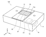
- FIG. 3 is an external image diagram of an ultraviolet irradiation device.
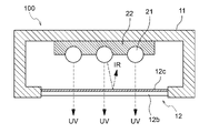
- FIG. 4 is a cross-sectional view showing a schematic configuration of an ultraviolet irradiation device.
- FIG. 5 is a cross-sectional view showing a schematic configuration of an ultraviolet irradiation device.
- FIG. 6 is a schematic configuration diagram showing another example of the disaster prevention system.
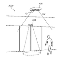
- FIG. 7 is a schematic configuration diagram showing an example of an ultraviolet irradiation system.
- FIG. 1 is a schematic configuration diagram of a disaster prevention system 1000 according to this embodiment.
- the disaster prevention system 1000 includes an ultraviolet irradiation device 100 that emits ultraviolet rays (UV) in a space 200 and a fire detector 300 that is installed in the space 200 and detects the occurrence of fire in the space 200 .
- the ultraviolet irradiation device 100 is a device that irradiates ultraviolet rays in the space 200 to inactivate harmful microorganisms and viruses existing in the space 200 and on the surfaces of objects in the space 200 .
- the ultraviolet irradiation device 100 includes an ultraviolet light source (emitter) that emits ultraviolet rays of, for example, 190 nm to 280 nm as ultraviolet rays in a wavelength range that inactivates microorganisms and/or viruses.
- the space 200 is a space within various facilities.
- the term “inactivation” as used herein refers to killing microorganisms and viruses (or losing their infectivity and toxicity).
- the ultraviolet irradiation device 100 emits ultraviolet rays with a wavelength of 190 nm to 235 nm (more preferably, ultraviolet rays in a wavelength range of 200 nm to 230 nm) that have little adverse effect on cells of humans and animals from the light emission window 12 into the space 200.
- the space 200 can be a space in which people or animals are present.
- the “space where people and animals exist” is not limited to spaces where people and animals actually exist, but includes spaces where people and animals enter and exit but where there are no people and animals.
- the fire detector 300 detects a fire by receiving infrared rays in a specific wavelength band emitted from flames.
- the infrared rays received by the fire detector 300 are infrared rays with a wavelength of around 4500 nm emitted by CO 2 resonance radiation generated during flaming combustion.
- the fire detector 300 detects a fire by receiving infrared rays with a detection wavelength band of 4200 nm to 4700 nm.
- the fire detector 300 has an infrared sensor (not shown) that receives infrared rays in the detection wavelength band, and determines that a fire has occurred when the infrared sensor receives infrared rays having an intensity equal to or higher than a predetermined threshold.
- the fire detector 300 may be configured to transmit a fire detection signal to a separate fire alarm (not shown) when determining that a fire has occurred, and cause the fire alarm to notify the fire. Furthermore, the fire detector 300 may be configured to operate a sprinkler provided in the space 200 when it determines that a fire has occurred.
- the ultraviolet irradiation device 100 and the fire detector 300 can be installed, for example, on the ceiling that forms the space 200 .
- the installation positions of the ultraviolet irradiation device 100 and the fire detector 300, the distance between them, and the like are not particularly limited.
- the ultraviolet light source included in the ultraviolet irradiation device 100 emits ultraviolet light when supplied with an electric current. At this time, the ultraviolet light source generates heat, and this heat may also radiate infrared light from the ultraviolet light source.
- the infrared detection type fire detector 300 when the infrared detection type fire detector 300 is installed in the space 200 where the ultraviolet irradiation device 100A irradiates ultraviolet rays, from the light emission window 12A of the ultraviolet irradiation device 100A When not only ultraviolet rays (UV) but also infrared rays (IR) are emitted, the infrared rays can enter the light receiving part of fire detector 300 directly or indirectly from ultraviolet irradiation device 100A.
- UV ultraviolet rays
- IR infrared rays
- the fire detector 300 When the fire detector 300 receives the infrared rays emitted from the ultraviolet irradiation device 100A and receives the infrared rays having an intensity equal to or higher than a predetermined threshold value, the fire detector 300 determines that a fire is occurring in the space 200. False detection will result in notification that a fire has occurred.
- the ultraviolet irradiation device 100 in this embodiment is configured so that the emission of infrared rays (infrared rays of 4200 nm to 4700 nm) in the detection wavelength band of the fire detector 300 from the light emission window 12 is blocked.
- the light emission window 12 of the ultraviolet irradiation device 100 is configured to include a member that inhibits transmission of infrared rays in the detection wavelength band by 90% or more.
- the member may be a member that inhibits transmission of infrared rays in the wavelength band by 95% or more, and may be composed of a member that inhibits transmission of infrared rays in the wavelength band by 99% or more. . This prevents the infrared detection type fire detector 300 from detecting infrared rays emitted from the ultraviolet irradiation device 100 and erroneously detecting that a fire is occurring in the space 200 .
- FIG. 3 is an external image diagram of the ultraviolet irradiation device 100.
- the ultraviolet irradiation device 100 has a housing 11 .
- An opening 11a is formed in the housing 11, and a light emission window 12 for emitting ultraviolet rays is provided in the opening 11a.
- a specific configuration of the light emission window 12 will be described later.
- An excimer lamp 20 is housed inside the housing 11 as an ultraviolet light source (light emitter).
- the excimer lamp 20 can be, for example, a KrCl excimer lamp that emits ultraviolet rays with a central wavelength of 222 nm.
- the ultraviolet light source is not limited to the KrCl excimer lamp, and may be any light source that emits ultraviolet light within the wavelength range of 190 nm to 235 nm.
- excimer lamps, LEDs, LDs, wavelength conversion elements, phosphors, etc. that emit ultraviolet rays in the wavelength range of 190 nm to 235 nm can be used.
- Ultraviolet rays have different penetrating powers into cells depending on the wavelength, and the shorter the wavelength, the smaller the penetrating power.
- short-wave UV light around 200 nm, passes through water very efficiently, but is highly absorbed by the outer part of human cells (the cytoplasm) and has sufficient energy to reach the cell nucleus, which contains UV-sensitive DNA. may not have Therefore, the above short-wave ultraviolet rays have little adverse effect on human cells.
- ultraviolet light with a wavelength exceeding 240 nm can damage DNA in human cell nuclei.
- the wavelength range of 190 to 240 nm is a safe wavelength range for humans and animals.
- an ultraviolet light source that emits ultraviolet light having a peak wavelength in a wavelength range of 190 nm to 235 nm, which has little adverse effect on the human body and provides an inactivation effect, is used.
- ultraviolet rays having a peak wavelength of 200 nm or more In order to more effectively suppress the generation of ozone in the atmosphere, it is desirable to use ultraviolet rays having a peak wavelength of 200 nm or more.
- An ultraviolet light source having a peak wavelength in the region of 200 nm to 230 nm may be used.
- the excimer lamp 20 has a straight tubular discharge vessel 21 hermetically sealed at both ends.
- the discharge vessel 21 can be made of quartz glass, for example.
- the discharge vessel 21 is filled with a rare gas and a halogen as a light emission gas.
- krypton chloride (KrCl) gas is used as the light emission gas.
- the peak wavelength of the emitted light obtained is 222 nm.
- the luminescent gas is not limited to the above.
- krypton bromide (KrBr) gas or the like can be used as the light emission gas.
- the peak wavelength of the resulting radiation is 207 nm.
- the ultraviolet irradiation device 100 includes a plurality (three) of discharge vessels 21, but the number of discharge vessels 21 is not particularly limited.
- a pair of electrodes (a first electrode 22 and a second electrode 23) are arranged on the outer surface of the discharge vessel 21 so as to be in contact with each other.
- the first electrode 22 and the second electrode 23 are arranged on the side surface of the discharge vessel 21 opposite to the light extraction surface (the surface in the -Z direction), spaced apart from each other in the tube axis direction (Y direction) of the discharge vessel 21. It is
- the discharge vessel 21 is arranged so as to straddle the two electrodes 22 while being in contact therewith. Specifically, grooves are formed in the two electrodes 22 and 23 , and the discharge vessel 21 is fitted in the grooves of the electrodes 22 and 23 .
- one electrode for example, the first electrode 22
- the other electrode for example, the second electrode 23
- the low-voltage side electrode ground electrode
- a light extraction surface of the excimer lamp 20 is arranged to face the light emission window 12 . Therefore, the light emitted from the excimer lamp 20 is emitted from the ultraviolet irradiation device 100 through the light emission window 12 .
- the electrodes 22 and 23 may be made of a metal member that reflects light emitted from the excimer lamp 21 . In this case, the light emitted from the discharge vessel 21 in the -Z direction can be reflected and propagated in the +Z direction.
- the ultraviolet irradiation device 100 includes a power supply unit 15 and a control unit 16 .
- the power supply unit 15 includes a power supply member such as an inverter to which power is supplied from the power supply, and a cooling member such as a heat sink for cooling the power supply member.
- the control unit 16 also controls lighting of the excimer lamp 20 .
- FIG. 4 is a schematic configuration diagram of the ultraviolet irradiation device 100 for explaining an example of the light emission window 12.
- the light emission window 12 is composed of an infrared absorbing member 12 a that transmits ultraviolet rays in a specific wavelength range and absorbs infrared rays in the detection wavelength band of the fire detector 300 .
- the specific wavelength range is a wavelength range of 190 nm to 235 nm which has little adverse effect on the human body.
- the infrared absorbing member 12a can have a structure in which an absorbing material that absorbs infrared rays is kneaded into a base material.
- the base material any member can be used as long as it can transmit ultraviolet rays in a specific wavelength range.
- the absorber include aluminum oxide (Al 2 O 3 ), silicon oxide (SiO 2 ), magnesium oxide (MgO), zirconia (ZrO 2 ), mullite (3Al 2 O 3.2SiO 2 ), zircon (ZrO 2.SiO 2 ), cordierite ( 2MgO.2Al 2 O 3.5SiO 2 ), and the like can be used.
- the infrared absorbing member 12a can also be configured using a material having a low infrared transmittance as the base material itself.
- the infrared absorbing member 12a has a portion made of quartz glass, silicone, fluorine-containing polymer, acryl, polycarbonate, polyester, polyethylene terephthalate, polytetrafluoroethylene, or the like.
- the infrared absorbing member 12a can be configured, for example, by forming a film (sheet) made of the above resin on a base material made of quartz glass. In this case, the resin can also serve as a diffusion member that diffuses light.
- FIG. 5 is a schematic configuration diagram of the ultraviolet irradiation device 100 for explaining another example of the light emission window 12.
- FIG. 5 also shows the housing 11 of the ultraviolet irradiation device 100, the discharge vessel 21 and the first electrode 22 of the excimer lamp 20, and the light emission window 12, and other constituent members are not shown. omitted.
- the light emission window 12 can be configured to have a base material 12b and a reflecting member 12c provided on a surface of the base material 12b facing the excimer lamp 20.
- the reflecting member 12 c reflects infrared rays emitted from the excimer lamp 20 to the inside of the housing 11 .
- the base material 12b can be quartz glass, for example.
- the base material 12b may be the infrared absorbing member 12a described above.
- the reflecting member 12c may be a dielectric multilayer film, for example. Examples of multilayer film materials include titanium oxide (TiO 2 , TiO 3 ), silicon oxide (SiO 2 ), niobium (Nb 2 O 5 ), tantalum oxide (Ta 2 O 3 , Ta 2 O 5 ), magnesium fluoride (MgF). 2 ) etc. can be used.
- the base material 12b and the reflecting member 12c are members that transmit ultraviolet rays in a specific wavelength range.
- an optical filter that transmits light in a specific wavelength range (wavelength range of 190 nm to 235 nm) and cuts a UVC wavelength band of 236 nm to 280 nm.
- the wavelength selection filter has a characteristic of reducing the illuminance of each ultraviolet ray having a wavelength of 236 nm to 280 nm to 1% or less with respect to the illuminance of ultraviolet ray having a peak wavelength in the wavelength band of 190 nm to 235 nm.
- the wavelength selection filter for example, an optical filter having a dielectric multilayer film of HfO 2 layers and SiO 2 layers can be used.
- an optical filter having a dielectric multilayer film of SiO 2 layers and Al 2 O 3 layers can be used as the wavelength selection filter.
- the light emission window 12 is configured to include a member that blocks 90% or more of transmission of infrared rays (infrared rays of 4200 nm to 4700 nm) in the detection wavelength band of the fire detector 300 as shown in FIG. 4 or FIG.
- an optical filter is provided which transmits ultraviolet light within a specific wavelength range (ultraviolet light of 190 nm to 235 nm) and blocks transmission of ultraviolet light outside the specific wavelength range.
- the ultraviolet irradiation device 100 includes the housing 11, the excimer lamp (light emitter) 20 that is housed inside the housing 11 and emits ultraviolet rays, and the excimer lamp 20 that is separated from the and a light emission window 12 provided in the housing 11 and transmitting ultraviolet rays in a specific wavelength range.
- this ultraviolet irradiation device 100 radiation of infrared rays having a wavelength of 4200 nm to 4700 nm from the light radiation window 12 is blocked.
- quartz glass is often used as a member constituting a light emission window provided in an ultraviolet irradiation device from the viewpoint of ultraviolet transmittance and durability.
- the light emission window may be provided with an optical filter for blocking unnecessary ultraviolet rays.
- quartz glass is known to have a property of being difficult to transmit infrared rays in the wavelength band of 4000 nm to 5000 nm.
- silica glass does not easily transmit infrared rays in the wavelength band of 5000 nm to 15000 nm.
- the transmittance of infrared rays is determined by the thickness of quartz glass and the content of impurities.
- the light emission window quartz glass
- the infrared rays emitted from the ultraviolet light source are emitted from the light emission window, and there is a possibility that the fire detector may misdetect when the ultraviolet irradiation device is used in the environment where the fire detector is installed.
- the light emission window 12 is configured to include a member that transmits ultraviolet rays in a specific wavelength range and blocks transmission of infrared rays in the detection wavelength band of the fire detector 300 by 90% or more. While emitting desired ultraviolet rays from the light emission window 12, it is possible to appropriately suppress emission of infrared rays that may cause false detection by the fire detector 300.
- FIG. 12 since a member having a low infrared transmittance is used for the light emission window 12 itself, or a member that absorbs or reflects infrared rays is provided in the base material of the light emission window 12, the light emission window 12 can be formed with a relatively simple structure.
- the light emission window 12 is provided in the housing 11 apart from the excimer lamp 20 which is the light emitter, heat transfer from the light emitter to the light emission window 12 can be suppressed. Therefore, it is possible to prevent the light radiation window 12 from becoming hot and radiating heat.
- the ultraviolet irradiation device 100 emits ultraviolet rays in a wavelength range that inactivates microorganisms and viruses harmful to the human body, it is possible to inactivate the environment while preventing erroneous detection by the fire detector 300. . Furthermore, since the ultraviolet irradiation device 100 emits ultraviolet rays in a wavelength range of 190 nm to 240 nm that have little adverse effect on cells of humans and animals, it is possible to sterilize and inactivate people in a space where people are present by irradiating ultraviolet rays. It can be performed.
- the ultraviolet irradiation device 100 reduces the probability of malfunction of the fire detector 300 in an environment in which an infrared detection type fire detector is installed, while reducing the possibility of microorganisms existing in the environment. and viruses can be properly inactivated. Therefore, the disaster prevention system 1000 according to the present embodiment can detect a fire with high sensitivity and accuracy while appropriately deactivating the environment using ultraviolet rays.
- the disaster prevention system 1000 in the above embodiment has been described as including the ultraviolet irradiation device 100 and the fire detector 300, it may further include an infrared radiation source 210 as shown in FIG.
- the infrared radiation source can be a halogen heater, stove, or the like installed in the space 200 .
- the disaster prevention system 1000 includes a shield 211 arranged on a straight line connecting the infrared radiation source 210 and the fire detector 300 to block infrared rays (IR) emitted from the infrared radiation source 210 .
- IR infrared rays
- FIG. 6 shows the case where the shield 211 is attached to the infrared radiation source 210, the shield 211 may be arranged on a straight line connecting the infrared radiation source 210 and the fire detector 300.
- the mounting position is not particularly limited.
- the disaster prevention system 1000 including the ultraviolet irradiation device 100 and the fire detector 300 has been described. It can also be applied to an ultraviolet irradiation system comprising
- the device can be, for example, a human sensor.
- the ultraviolet irradiation device 100 has a configuration in which the emission of infrared rays in a wavelength band including the detection wavelength band of the device is blocked from the light emission window 12 .
- the ultraviolet irradiation device 100 can be configured such that the radiation of infrared rays belonging to the wavelength band of 4000 nm to 15000 nm from the light radiation window 12 is blocked.
- a member that inhibits transmission of infrared rays belonging to the wavelength band by 90% or more can be provided, and further, a member that inhibits transmission of infrared rays belonging to the wavelength band by 95% or more, further 99% or more. be able to.
- FIG. 7 is a schematic configuration diagram showing an example of an ultraviolet irradiation system 2000.
- the ultraviolet irradiation system 2000 includes an ultraviolet irradiation device 100 and a human sensor 400 installed at an automatic door to detect a person approaching the automatic door.
- the human sensor 400 is an infrared sensor that operates by detecting infrared rays emitted from a human body with a detection wavelength band of 5000 nm to 15000 nm, and detects the presence of a person by detecting infrared rays in the detection wavelength band. do.
- the human sensor 400 transmits a human body detection signal to a control device (not shown) that controls opening and closing of the automatic door.
- the control device receives a human body detection signal from the human sensor 400 and controls the automatic door to open.
- the ultraviolet irradiation device 100 can be installed, for example, on the ceiling near the automatic door.
- the human sensor 400 can be installed, for example, above an automatic door. Note that the installation positions of the ultraviolet irradiation device 100 and the human sensor 400 are not limited to the positions shown in FIG.
- the ultraviolet irradiation device 100 is configured such that infrared radiation from the light radiation window 12 is blocked. Specifically, the ultraviolet irradiation device 100 is configured to block the radiation of infrared rays in the wavelength band of 5000 nm to 10000 nm, which is the detection wavelength band of the human sensor 400, and further in the wavelength band of 5000 nm to 15000 nm.
- the human body emits infrared rays with a peak wavelength of 9000 nm to 10000 nm, and the human sensor 400 operates by receiving the infrared rays. It is preferable that
- the ultraviolet irradiation device 100 can have, for example, the configuration shown in FIG.
- the light emission window 12 of the ultraviolet irradiation device 100 can be composed of an infrared absorption member 12 a that transmits ultraviolet rays in a specific wavelength range and absorbs infrared rays in the detection wavelength band of the human sensor 400 .
- the infrared absorbing member 12a uses, for example, silica glass as a base material that does not easily transmit infrared rays in a wavelength band of 5000 nm to 10000 nm, and further, 5000 nm to 15000 nm. Inhibits infrared rays from being emitted.
- the base material may be kneaded with an impurity or an absorbing material that absorbs infrared rays in the wavelength band of 5000 nm to 10000 nm, furthermore, 5000 nm to 15000 nm.
- the infrared absorbing member 12a has a structure in which a film (sheet) made of a resin having a low transmittance of infrared rays in a wavelength band of 5000 nm to 10000 nm, further 5000 nm to 15000 nm is formed on a base material made of quartz glass, for example.
- the infrared absorbing member 12a is composed of a member that inhibits the transmission of infrared rays in the wavelength band of 5000 nm to 10000 nm by 90% or more, furthermore, the infrared rays in the wavelength band are transmitted by 95% or more. , 99% or more.
- the ultraviolet irradiation device 100 can be configured as shown in FIG. 5, for example. That is, the light emission window 12 of the ultraviolet irradiation device 100 can be configured to have a base material 12b made of, for example, quartz glass, and a reflecting member 12c provided on the surface of the base material 12b facing the excimer lamp 20. can.
- the reflective member 12c may be made of a material that reflects infrared rays in a wavelength band of 5000 nm to 10000 nm, further 5000 nm to 15000 nm.
- the configuration of the ultraviolet irradiation device 100 is not limited to the above. , as long as it does not radiate infrared rays. With such a configuration, it is possible to prevent the human sensor 400 from receiving the infrared rays emitted from the ultraviolet irradiation device 100 and erroneously detecting the presence of a person in front of the automatic door. As a result, it is possible to prevent the automatic door from malfunctioning.
- the facility in which the human sensor 400 is installed is not limited to the automatic door described above.
- the facility in which the human sensor 400 is installed may be the ultraviolet irradiation device 100 .
- the ultraviolet irradiation device 100 may include the human sensor 400 .
- the ultraviolet irradiation device 100 can control the lighting and extinguishing of the excimer lamp 20 as the light source based on the human body detection signal from the human sensor 400 .
- the ultraviolet irradiation device 100 may irradiate ultraviolet rays from the light emitting surface 12 while the human sensor 400 detects the presence of a person, or the human sensor 400 may detect the presence of a person. UV irradiation from the light emitting surface 12 may be stopped or reduced during the period.
- the above-described ultraviolet irradiation device 100 reduces the probability of malfunction of the device in an environment where the device such as the infrared detection type human sensor 400 is installed. Viruses can be properly inactivated. Therefore, the ultraviolet irradiation system 2000 can operate the equipment with high sensitivity and high accuracy while appropriately carrying out deactivation in the environment using ultraviolet rays.
- the ultraviolet irradiation system 2000 may include a plurality of types of devices that operate by receiving infrared rays.
- the detection wavelength bands of multiple types of devices may be different.
- the ultraviolet irradiation system 2000 may include both the fire detector 300 and the human sensor 400 described above.
- the light emission window 12 of the ultraviolet irradiation device 100 has a wavelength band that includes both the detection wavelength band (wavelength 4200 nm to 4700 nm) of the fire detector 300 and the detection wavelength band (wavelength 5000 nm to 15000 nm) of the human sensor 400. has a configuration in which the radiation of infrared rays is inhibited.
- quartz glass has a property of being difficult to transmit infrared rays belonging to the wavelength band of 4000 nm to 15000 nm. Therefore, by adjusting the material and thickness, the light emission window 12 of the ultraviolet irradiation device 100 is blocked from emitting any infrared rays belonging to the wavelength band of 4000 nm to 15000 nm or all infrared rays in the wavelength band. It is also easy to configure.
- a fire detector 300 is installed in a space where an automatic door equipped with a human sensor 400 shown in FIG. Even in a harsh environment, it is possible to appropriately inactivate microorganisms and viruses existing in the environment while appropriately reducing the probability of malfunction of these devices.
- the excimer lamp 20 which is the ultraviolet light source, has a structure in which a pair of electrodes 22 and 23 are arranged on one side surface of the discharge vessel 21 as shown in FIG.
- the configuration of the excimer lamp is not limited to the above.
- a configuration in which a pair of annular electrodes (a first electrode and a second electrode) are arranged at both ends of an elongated discharge vessel may be used.
- the long discharge vessel has an inner electrode (first electrode) inside, and the outer wall surface of the discharge vessel has a mesh-like (mesh shape) or linear outer electrode (second electrode). good too.
- a so-called “flat tube structure” may be employed in which a first electrode and a second electrode are provided on two opposite outer surfaces of a flat discharge vessel.
- a so-called “double tube structure” consisting of a cylindrical outer tube and a cylindrical inner tube may be employed.
- a mesh-like first electrode (external electrode) and a film-like second electrode (internal electrode) can be arranged on the outer surface of the outer tube and the inner surface of the inner tube, respectively.
- an LED can also be used as the ultraviolet light source.
- an LED for example, an aluminum gallium nitride (AlGaN)-based LED, an aluminum nitride (AlN)-based LED, a magnesium zinc oxide (MgZnO)-based LED, or the like can be employed.
- AlGaN-based LED it is preferable to adjust the Al composition so that the center wavelength is within the range of 200 to 235 nm.
- AlN-based LEDs emit ultraviolet rays with a peak wavelength of 210 nm.
- the MgZnO-based LED can emit ultraviolet light with a center wavelength of 222 nm by adjusting the composition of Mg.
- the surface of the LED chip may be coated with a material having low infrared transmittance.
- the material can be, for example, glass, silicone, fluorine-containing polymer, acrylic, polycarbonate, polyester, polyethylene terephthalate, polytetrafluoroethylene, or the like.
- the light emission window 12 does not necessarily need to include a member that inhibits transmission of infrared rays, and the light emission window 12 may be configured to transmit ultraviolet rays in a specific wavelength range.
- the ultraviolet light emitted from the ultraviolet light source may be ultraviolet light within a wavelength range (for example, a wavelength of 190 nm to 280 nm) capable of inactivating harmful microorganisms and viruses. That is, the ultraviolet light source is not limited to the excimer lamps and LEDs described above, and may be, for example, a low-pressure mercury lamp that emits ultraviolet rays with a wavelength of 253.7 nm.
- the ultraviolet light emitted from the ultraviolet light source is not in the wavelength range of 190 nm to 240 nm, which has little adverse effect on the human body, it should not be emitted into the space where people are present. It is preferable to configure such that the irradiation is stopped or the ultraviolet rays are blocked so as not to be emitted.
- the ultraviolet irradiation device 100 is an inactivation device that inactivates harmful microorganisms and viruses in the space 200 has been described, but it is not limited to the above.
- the ultraviolet irradiation device 100 may be any device that emits ultraviolet rays in the space 200, and the ultraviolet rays emitted from the ultraviolet light source may be ultraviolet rays of any wavelength depending on the application.
- the ultraviolet irradiation device by using ultraviolet rays with a wavelength of 190 nm to 235 nm, it is possible to provide the original sterilization and virus inactivation capabilities of ultraviolet rays without adversely affecting the human body due to ultraviolet irradiation. .
- effective deactivation treatment with ultraviolet light can be performed even in spaces where people are present. This corresponds to Goal 3 of the United Nations-led Sustainable Development Goals (SDGs), "Ensure healthy lives and promote well-being for all at all ages", and also to Target 3.3. It will make a significant contribution to “by 2030, end epidemics such as AIDS, tuberculosis, malaria and neglected tropical diseases, and combat hepatitis, water-borne diseases and other communicable diseases”.
- SYMBOLS 11 Housing, 12... Light emission window, 15... Power supply part, 16... Control part, 20... Excimer lamp, 21... Discharge container, 22... First electrode, 23... Second electrode, 100... Ultraviolet irradiation device, 200 ... space, 300 ... fire detector, 400 ... human sensor
Landscapes
- Business, Economics & Management (AREA)
- General Physics & Mathematics (AREA)
- Physics & Mathematics (AREA)
- Health & Medical Sciences (AREA)
- Emergency Management (AREA)
- Animal Behavior & Ethology (AREA)
- Veterinary Medicine (AREA)
- Public Health (AREA)
- General Health & Medical Sciences (AREA)
- Life Sciences & Earth Sciences (AREA)
- Epidemiology (AREA)
- Apparatus For Disinfection Or Sterilisation (AREA)
- Fire-Detection Mechanisms (AREA)
- Fire Alarms (AREA)
- Photometry And Measurement Of Optical Pulse Characteristics (AREA)
Abstract
赤外線を受光して動作する機器が設置された環境下において、当該機器の誤動作の発生確率を低下させつつも、紫外線照射装置を適切に動作させることが可能なシステムを開示する。 防災システム(1000)は、空間内において紫外線を放射する紫外線照射装置と、空間内に設置され、所定の検知波長帯の赤外線を受光して当該空間内における火災の発生を検知する火災検知器と、を備える。上記検知波長帯は、波長4200nm~4700nmの波長帯である。紫外線照射装置は、筐体と、筐体の内部に収容されて紫外線を放射する発光体と、発光体から離間して筐体に設けられ、特定波長範囲の紫外線を透過する光放射窓と、を備え、光放射窓からの検知波長帯の赤外線の放射が阻害されている。
Description
本発明は、赤外線の検知により火災を検知する火災検知器を備える防災システムおよび赤外線を受光して動作する機器を備える紫外線照射システムに関する。
従来、火災を検知する火災検知器として、炎から放射される光を検知する光検知式の火災検知器がある。光検知式の火災検知器は、初期火災の検知が可能であり、かつ、火災現場の熱を検知する熱検知式の火災検知器や煙を検知する煙検知式の火災検知器よりも検知範囲が広いという利点があり、高感度の火災検知器として使用されている。
光検知式の火災検知器としては、炎から放射される赤外線を検知する赤外線検知式の火災検知器がある(例えば、特許文献1参照)。
光検知式の火災検知器としては、炎から放射される赤外線を検知する赤外線検知式の火災検知器がある(例えば、特許文献1参照)。
近年の感染症の世界的大流行を契機として、環境中に存在する細菌やウイルスに紫外線を照射することで、細菌やウイルスを不活化させることが、感染予防対策として期待されている。
しかしながら、紫外線を発生させる光源からは、光源自身から発せられる光や熱によって赤外線が放射される。そのため、赤外線検知式の機器(例えば火災検知器など)を設置した施設内や乗り物内において、紫外線照射による細菌やウイルスの不活化を行う場合、紫外線光源から放射される赤外線が上記機器の受光部に直接的または間接的に照射されることで、上記機器が誤動作してしまうことがある。特に、紫外線光源から放射される光量を増大させるために、紫外線光源に大電流を供給する場合には、紫外線光源の発熱量が増大し、上記誤動作を招きやすい。
つまり、赤外線検知式の火災検知器等の赤外線を受光して動作する機器を設置した環境下では、空間内に紫外線を放射する紫外線照射処理を十分に実施することが難しい。
しかしながら、紫外線を発生させる光源からは、光源自身から発せられる光や熱によって赤外線が放射される。そのため、赤外線検知式の機器(例えば火災検知器など)を設置した施設内や乗り物内において、紫外線照射による細菌やウイルスの不活化を行う場合、紫外線光源から放射される赤外線が上記機器の受光部に直接的または間接的に照射されることで、上記機器が誤動作してしまうことがある。特に、紫外線光源から放射される光量を増大させるために、紫外線光源に大電流を供給する場合には、紫外線光源の発熱量が増大し、上記誤動作を招きやすい。
つまり、赤外線検知式の火災検知器等の赤外線を受光して動作する機器を設置した環境下では、空間内に紫外線を放射する紫外線照射処理を十分に実施することが難しい。
そこで、本発明は、赤外線を受光して動作する機器が設置された環境下において、当該機器の誤動作の発生確率を低下させつつも、紫外線照射装置を適切に動作させることが可能なシステムを提供することを課題としている。
上記課題を解決するために、本発明に係る防災システムの一態様は、空間内において紫外線を放射する紫外線照射装置と、前記空間内に設置され、所定の検知波長帯の赤外線を受光して当該空間内における火災の発生を検知する火災検知器と、を備え、前記検知波長帯は、波長4200nm~4700nmの波長帯であって、前記紫外線照射装置は、筐体と、前記筐体の内部に収容されて紫外線を放射する発光体と、前記発光体から離間して前記筐体に設けられ、特定波長範囲の紫外線を透過する光放射窓と、を備え、前記光放射窓からの前記検知波長帯の赤外線の放射が阻害されている。
このように、紫外線照射装置の光放射窓から火災検知器の検知波長帯の赤外線が放射されることが阻害されているので、赤外線検知式の火災検知器が設置された環境下において紫外線照射装置を使用した場合であっても、紫外線照射装置の動作によって火災検知器が誤検知を起こすことを適切に抑制することができる。
このように、紫外線照射装置の光放射窓から火災検知器の検知波長帯の赤外線が放射されることが阻害されているので、赤外線検知式の火災検知器が設置された環境下において紫外線照射装置を使用した場合であっても、紫外線照射装置の動作によって火災検知器が誤検知を起こすことを適切に抑制することができる。
また、上記の防災システムにおいて、前記光放射窓は、前記検知波長帯の赤外線の透過を90%以上阻害する部材を含んで構成されていてもよい。
この場合、光放射窓からの上記検知波長帯の赤外線の放射を適切に阻害することができる。
この場合、光放射窓からの上記検知波長帯の赤外線の放射を適切に阻害することができる。
さらに、上記の防災システムにおいて、前記光放射窓は、石英ガラス、シリコーン、含フッ素ポリマー、アクリル、ポリカーボネート、ポリエステル、ポリエチレンテレフタレートおよびポリテトラフルオロエチレンのいずれかにより構成されていてもよい。
この場合、光放射窓を構成する母材自体の赤外線透過率を下げることができ、簡易な構成で光放射窓からの上記検知波長帯の赤外線の放射を適切に阻害することができる。
この場合、光放射窓を構成する母材自体の赤外線透過率を下げることができ、簡易な構成で光放射窓からの上記検知波長帯の赤外線の放射を適切に阻害することができる。
また、上記の防災システムにおいて、前記光放射窓における前記発光体と対向する面には、前記検知波長帯の赤外線を前記筐体の内部に反射する反射部材が設けられていてもよい。
この場合、発光体から放射される熱線を光放射窓に設けられた反射部材によって筐体内部へ反射し、光放射窓から筐体外部へ放射されることを適切に抑制することができる。
この場合、発光体から放射される熱線を光放射窓に設けられた反射部材によって筐体内部へ反射し、光放射窓から筐体外部へ放射されることを適切に抑制することができる。
さらに、上記の防災システムにおいて、前記光放射窓には、前記検知波長帯の赤外線を吸収する吸収材が練り込まれていてもよい。
この場合、発光体から放射される熱線を、光放射窓を構成する母材に練り込まれた吸収材によって吸収し、光放射窓から筐体外へ放射されることを適切に抑制することができる。
この場合、発光体から放射される熱線を、光放射窓を構成する母材に練り込まれた吸収材によって吸収し、光放射窓から筐体外へ放射されることを適切に抑制することができる。
また、上記の防災システムにおいて、前記発光体はLEDチップであって、前記LEDチップの表面は、ガラス、シリコーン、含フッ素ポリマー、アクリル、ポリカーボネート、ポリエステル、ポリエチレンテレフタレートおよびポリテトラフルオロエチレンのいずれかにより被覆されていてもよい。
このように、発光体を赤外線透過率の低い樹脂により被覆することで、発光体から熱線が放射されること抑制することができる。
このように、発光体を赤外線透過率の低い樹脂により被覆することで、発光体から熱線が放射されること抑制することができる。
また、上記の防災システムにおいて、前記発光体は、微生物および/またはウイルスを不活化する波長範囲の紫外線を放射される。
この場合、赤外線検知式の火災検知器が設置された環境下において、火災検知器による誤検知を抑制しつつ、空間内に存在する微生物やウイルスを不活化させるための紫外線照射を適切に実施することができる。
この場合、赤外線検知式の火災検知器が設置された環境下において、火災検知器による誤検知を抑制しつつ、空間内に存在する微生物やウイルスを不活化させるための紫外線照射を適切に実施することができる。
また、上記の防災システムにおいて、前記特定波長範囲は、190nm~235nmの波長範囲に属し、前記光放射窓には、波長235nmよりも長波長側のUV-C波の透過を阻止する光学フィルタが設けられていてもよい。
この場合、人体や動物への悪影響の少ない波長域の紫外線のみを照射することができる。
この場合、人体や動物への悪影響の少ない波長域の紫外線のみを照射することができる。
さらに、上記の防災システムは、前記空間内に配置されて赤外線を放射する赤外線放射源と、前記赤外線放射源と前記火災検知器とを結ぶ直線上に配置され、前記赤外線放射源から放射される赤外線を遮蔽する遮蔽体と、をさらに備えていてもよい。
この場合、赤外線検知式の火災検知器が設置された環境に、例えばハロゲンヒーターやストーブ等の赤外線放射源が設置されている場合であっても、赤外線放射源から放射される赤外線を火災検知器が受光してしまうことを抑制することができ、火災検知器の誤検知を適切に抑制することができる。
この場合、赤外線検知式の火災検知器が設置された環境に、例えばハロゲンヒーターやストーブ等の赤外線放射源が設置されている場合であっても、赤外線放射源から放射される赤外線を火災検知器が受光してしまうことを抑制することができ、火災検知器の誤検知を適切に抑制することができる。
また、本発明に係る紫外線照射システムの一態様は、空間内において紫外線を放射する紫外線照射装置と、前記空間内に設置され、所定の検知波長帯の赤外線を受光して動作する機器と、を備え、前記紫外線照射装置は、筐体と、前記筐体の内部に収容されて紫外線を放射する発光体と、前記発光体から離間して前記筐体に設けられ、特定波長範囲の紫外線を透過する光放射窓と、を備え、前記光放射窓からの前記検知波長帯の赤外線の放射が阻害されている。
このように、紫外線照射装置の光放射窓から、赤外線を受光して動作する機器の検知波長帯の赤外線が放射されることが阻害されているので、赤外線検知式の機器が設置された環境下において紫外線照射装置を使用した場合であっても、紫外線照射装置の動作によって上記機器が誤検知を起こすことを適切に抑制することができる。
このように、紫外線照射装置の光放射窓から、赤外線を受光して動作する機器の検知波長帯の赤外線が放射されることが阻害されているので、赤外線検知式の機器が設置された環境下において紫外線照射装置を使用した場合であっても、紫外線照射装置の動作によって上記機器が誤検知を起こすことを適切に抑制することができる。
また、本発明に係る紫外線照射装置の一態様は、筐体と、前記筐体の内部に収容されて紫外線を放射する発光体と、前記発光体から離間して前記筐体に設けられ、特定波長範囲の紫外線を透過する光放射窓と、を備え、前記光放射窓からの波長4000nm~15000nmの波長帯域に属する赤外線の放射が阻害されている。
このように、光放射窓から波長4000nm~15000nmの波長帯域に属する赤外線が放射されることが阻害されているので、上記波長帯域に検知波長帯が含まれる赤外線検知式の機器が設置された環境下においても、上記機器が誤検知を起こすことを適切に抑制しつつ、紫外線照射を実施することができる。
このように、光放射窓から波長4000nm~15000nmの波長帯域に属する赤外線が放射されることが阻害されているので、上記波長帯域に検知波長帯が含まれる赤外線検知式の機器が設置された環境下においても、上記機器が誤検知を起こすことを適切に抑制しつつ、紫外線照射を実施することができる。
上記紫外線照射装置において、前記光放射窓からの波長4200nm~4700nmの赤外線の放射が阻害されていてもよい。
この場合、波長4200nm~4700nmの波長帯を検知波長帯とする赤外線検知式の火災検知器が設置された環境下においても、火災検知器が誤検知を起こすことを適切に抑制しつつ、紫外線照射を実施することができる。
この場合、波長4200nm~4700nmの波長帯を検知波長帯とする赤外線検知式の火災検知器が設置された環境下においても、火災検知器が誤検知を起こすことを適切に抑制しつつ、紫外線照射を実施することができる。
また、上記紫外線照射装置において、前記光放射窓からの波長5000nm~10000nmの赤外線の放射が阻害されていてもよい。
この場合、波長5000nm~10000nmの波長帯を検知波長帯とする赤外線検知式の機器が設置された環境下においても、上記機器が誤検知を起こすことを適切に抑制しつつ、紫外線照射を実施することができる。
この場合、波長5000nm~10000nmの波長帯を検知波長帯とする赤外線検知式の機器が設置された環境下においても、上記機器が誤検知を起こすことを適切に抑制しつつ、紫外線照射を実施することができる。
本発明の一つの態様によれば、赤外線を受光して動作する機器が設置された環境下において、当該機器の誤動作の発生確率を低下させつつも、紫外線照射装置を適切に動作させることができる。
上記した本発明の目的、態様及び効果並びに上記されなかった本発明の目的、態様及び効果は、当業者であれば添付図面及び請求の範囲の記載を参照することにより下記の発明を実施するための形態(発明の詳細な説明)から理解できるであろう。
上記した本発明の目的、態様及び効果並びに上記されなかった本発明の目的、態様及び効果は、当業者であれば添付図面及び請求の範囲の記載を参照することにより下記の発明を実施するための形態(発明の詳細な説明)から理解できるであろう。
以下、本発明の実施形態を図面に基づいて説明する。
図1は、本実施形態における防災システム1000の概略構成図である。
防災システム1000は、空間200内において紫外線(UV)を放射する紫外線照射装置100と、空間200内に設置されて当該空間200における火災の発生を検知する火災検知器300と、を備える。
紫外線照射装置100は、空間200内において紫外線照射を行い、空間200や空間200内の物体表面に存在する有害な微生物やウイルスを不活化する装置である。紫外線照射装置100は、微生物および/またはウイルスを不活化する波長範囲の紫外線として、例えば190nm~280nmの紫外線を放射する紫外線光源(発光体)を備える。ここで、空間200は、各種施設内の空間である。
なお、ここでいう「不活化」とは、微生物やウイルスを死滅させる(又は感染力や毒性を失わせる)ことを指すものである。
図1は、本実施形態における防災システム1000の概略構成図である。
防災システム1000は、空間200内において紫外線(UV)を放射する紫外線照射装置100と、空間200内に設置されて当該空間200における火災の発生を検知する火災検知器300と、を備える。
紫外線照射装置100は、空間200内において紫外線照射を行い、空間200や空間200内の物体表面に存在する有害な微生物やウイルスを不活化する装置である。紫外線照射装置100は、微生物および/またはウイルスを不活化する波長範囲の紫外線として、例えば190nm~280nmの紫外線を放射する紫外線光源(発光体)を備える。ここで、空間200は、各種施設内の空間である。
なお、ここでいう「不活化」とは、微生物やウイルスを死滅させる(又は感染力や毒性を失わせる)ことを指すものである。
本実施形態では、紫外線照射装置100は、光放射窓12から、人や動物の細胞への悪影響が少ない波長190nm~235nmの紫外線(より好ましくは、波長域200nm~230nmの紫外線)を空間200に対して照射する場合について説明する。この場合、空間200は、人や動物が存在する空間とすることができる。
なお、「人や動物が存在する空間」とは、実際に人や動物がいる空間に限定されず、人や動物が出入りする空間であって人や動物がいない空間を含む。
なお、「人や動物が存在する空間」とは、実際に人や動物がいる空間に限定されず、人や動物が出入りする空間であって人や動物がいない空間を含む。
火災検知器300は、炎から放射される特有の波長帯の赤外線を受光し、火災を検知する。ここで、火災検知器300が受光する赤外線は、有炎燃焼時に発生するCO2共鳴放射により放射される波長4500nm前後の赤外線である。具体的には、火災検知器300は、4200nm~4700nmの波長帯を検知波長帯として赤外線を受光し、火災を検知する。
火災検知器300は、上記検知波長帯の赤外線を受光する不図示の赤外線センサを有し、当該赤外線センサによって所定の閾値以上の強度の赤外線が受光された場合に、火災が発生したと判定し、警報を発する。なお、火災検知器300は、火災が発生したと判定した場合、別体の火災報知器(不図示)に火災検知信号を送信し、火災報知器に火災を報知させる構成であってもよい。さらに、火災検知器300は、火災が発生したと判定した場合、空間200に設けられたスプリンクラーを動作させるように構成されていてもよい。
火災検知器300は、上記検知波長帯の赤外線を受光する不図示の赤外線センサを有し、当該赤外線センサによって所定の閾値以上の強度の赤外線が受光された場合に、火災が発生したと判定し、警報を発する。なお、火災検知器300は、火災が発生したと判定した場合、別体の火災報知器(不図示)に火災検知信号を送信し、火災報知器に火災を報知させる構成であってもよい。さらに、火災検知器300は、火災が発生したと判定した場合、空間200に設けられたスプリンクラーを動作させるように構成されていてもよい。
紫外線照射装置100および火災検知器300は、例えば空間200を形成する天井に設置することができる。
なお、紫外線照射装置100および火災検知器300の設置位置や両者の離間距離などは特に限定されない。
なお、紫外線照射装置100および火災検知器300の設置位置や両者の離間距離などは特に限定されない。
紫外線照射装置100が備える紫外線光源は、電流が供給されることで紫外線を放射する。このとき、紫外線光源が発熱し、この熱によって紫外線光源から赤外線も放射される場合がある。
図2に示す防災システム1000Aのように、紫外線照射装置100Aが紫外線を照射する空間200内に、赤外線検知式の火災検知器300が設置されている場合、紫外線照射装置100Aの光放射窓12Aから紫外線(UV)だけでなく赤外線(IR)も放射されると、その赤外線は、紫外線照射装置100Aから直接的または間接的に火災検知器300の受光部に入射されうる。そして、火災検知器300が紫外線照射装置100Aから放射される赤外線を受光し、所定の閾値以上の強度の赤外線が受光されると、火災検知器300は空間200内において火災が発生していると誤検知し、火災が発生していることが報知されてしまう。
図2に示す防災システム1000Aのように、紫外線照射装置100Aが紫外線を照射する空間200内に、赤外線検知式の火災検知器300が設置されている場合、紫外線照射装置100Aの光放射窓12Aから紫外線(UV)だけでなく赤外線(IR)も放射されると、その赤外線は、紫外線照射装置100Aから直接的または間接的に火災検知器300の受光部に入射されうる。そして、火災検知器300が紫外線照射装置100Aから放射される赤外線を受光し、所定の閾値以上の強度の赤外線が受光されると、火災検知器300は空間200内において火災が発生していると誤検知し、火災が発生していることが報知されてしまう。
そこで、本実施形態における紫外線照射装置100は、光放射窓12からの火災検知器300の検知波長帯の赤外線(4200nm~4700nmの赤外線)の放射が阻害されるように構成する。具体的には、紫外線照射装置100の光放射窓12を、上記検知波長帯の赤外線の透過を90%以上阻害する部材を含んで構成する。ここで当該部材は、当該波長帯域の赤外線の透過を95%以上阻害する部材であってもよく、更には、当該波長帯域の赤外線の透過を99%以上阻害する部材で構成されていてもよい。
これにより、赤外線検知式の火災検知器300が、紫外線照射装置100から放射される赤外線を検知して空間200内において火災が発生していると誤検知してしまうことを防止することができる。
これにより、赤外線検知式の火災検知器300が、紫外線照射装置100から放射される赤外線を検知して空間200内において火災が発生していると誤検知してしまうことを防止することができる。
図3は、紫外線照射装置100の外観イメージ図である。
図3に示すように、紫外線照射装置100は、筐体11を備える。筐体11には開口部11aが形成されており、開口部11aには、紫外線を放射する光放射窓12が設けられている。光放射窓12の具体的構成については後述する。
筐体11内部には、紫外線光源(発光体)として、エキシマランプ20が収容されている。エキシマランプ20は、例えば中心波長222nmの紫外線を放出するKrClエキシマランプとすることができる。なお、紫外線光源は、KrClエキシマランプに限定されるものではなく、190nm~235nmの波長範囲に属する紫外線を放射する光源であればよい。例えば、190nm~235nmの波長範囲に属する紫外線を放射するエキシマランプ、LED、LD、波長変換素子、蛍光体等を用いることができる。
図3に示すように、紫外線照射装置100は、筐体11を備える。筐体11には開口部11aが形成されており、開口部11aには、紫外線を放射する光放射窓12が設けられている。光放射窓12の具体的構成については後述する。
筐体11内部には、紫外線光源(発光体)として、エキシマランプ20が収容されている。エキシマランプ20は、例えば中心波長222nmの紫外線を放出するKrClエキシマランプとすることができる。なお、紫外線光源は、KrClエキシマランプに限定されるものではなく、190nm~235nmの波長範囲に属する紫外線を放射する光源であればよい。例えば、190nm~235nmの波長範囲に属する紫外線を放射するエキシマランプ、LED、LD、波長変換素子、蛍光体等を用いることができる。
紫外線は、波長によって細胞の貫通力が異なり、短波長ほど当該貫通力が小さい。例えば、約200nmといった短波長の紫外線は、非常に効率良く水を通過するものの、ヒト細胞の外側部分(細胞質)による吸収が大きく、紫外線に敏感なDNAを含む細胞核に到達するのに十分なエネルギーを有さない場合がある。そのため、上記の短波長の紫外線は、ヒト細胞に対する悪影響が少ない。一方で、波長240nmを超える紫外線は、ヒトの細胞核中のDNAにダメージを与えうる。また、波長190nm未満の紫外光が存在すると、大気中に存在する酸素分子が光分解されて酸素原子を多く生成し、酸素分子と酸素原子との結合反応によってオゾンを多く生成させてしまう。そのため、波長190nm未満の紫外光を大気中に照射させることは望ましくない。したがって、波長190~240nmの波長範囲は、人や動物に安全な波長範囲であるといえる。
本実施形態では、紫外線光源として、人体への悪影響が少なく、不活化効果が得られる波長域190nm~235nmにピーク波長を有する紫外線を放射する紫外線光源を用いる。また、大気中のオゾン発生をより効果的に抑制するため200nm以上にピーク波長を有する紫外線を利用することが望ましく、さらに安全性の高い波長帯域としてより短波長帯域の紫外線が望ましく、例えば、波長域200nm~230nmにピーク波長を有する紫外線光源を用いてもよい。
本実施形態では、紫外線光源として、人体への悪影響が少なく、不活化効果が得られる波長域190nm~235nmにピーク波長を有する紫外線を放射する紫外線光源を用いる。また、大気中のオゾン発生をより効果的に抑制するため200nm以上にピーク波長を有する紫外線を利用することが望ましく、さらに安全性の高い波長帯域としてより短波長帯域の紫外線が望ましく、例えば、波長域200nm~230nmにピーク波長を有する紫外線光源を用いてもよい。
エキシマランプ20は、両端が気密に封止された直管状の放電容器21を備える。放電容器21は、例えば石英ガラスにより構成することができる。また、放電容器21の内部には、発光ガスとして希ガスとハロゲンとが封入されている。本実施形態では、発光ガスとして、塩化クリプトン(KrCl)ガスを用いる。この場合、得られる放射光のピーク波長は222nmである。
なお、発光ガスは上記に限定されない。例えば、発光ガスとして臭化クリプトン(KrBr)ガス等を用いることもできる。KrBrエキシマランプの場合、得られる放射光のピーク波長は207nmである。
また、図3では、紫外線照射装置100が複数(3本)の放電容器21を備えているが、放電容器21の数は特に限定されない。
なお、発光ガスは上記に限定されない。例えば、発光ガスとして臭化クリプトン(KrBr)ガス等を用いることもできる。KrBrエキシマランプの場合、得られる放射光のピーク波長は207nmである。
また、図3では、紫外線照射装置100が複数(3本)の放電容器21を備えているが、放電容器21の数は特に限定されない。
放電容器21の外表面には、一対の電極(第一電極22、第二電極23)が当接するように配置されている。第一電極22および第二電極23は、放電容器21における光取出し面とは反対側の側面(-Z方向の面)に、放電容器21の管軸方向(Y方向)に互いに離間して配置されている。
そして、放電容器21は、これら2つの電極22、22に接触しながら跨るように配置されている。具体的には、2つの電極22、23には凹溝が形成されており、放電容器21は、電極22、23の凹溝に嵌め込まれている。
そして、放電容器21は、これら2つの電極22、22に接触しながら跨るように配置されている。具体的には、2つの電極22、23には凹溝が形成されており、放電容器21は、電極22、23の凹溝に嵌め込まれている。
この一対の電極のうち、一方の電極(例えば第一電極22)が高圧側電極であり、他方の電極(例えば第二電極23)が低圧側電極(接地電極)である。第一電極22および第二電極23の間に高周波電圧を印加することで、ランプが点灯される。
エキシマランプ20の光取出し面は、光放射窓12に対向して配置される。そのため、エキシマランプ20から放射された光は、光放射窓12を介して紫外線照射装置100から出射される。
ここで、電極22、23は、エキシマランプ21から放射される光に対して反射性を有する金属部材により構成されていてもよい。この場合、放電容器21から-Z方向に放射された光を反射して+Z方向に進行させることができる。
ここで、電極22、23は、エキシマランプ21から放射される光に対して反射性を有する金属部材により構成されていてもよい。この場合、放電容器21から-Z方向に放射された光を反射して+Z方向に進行させることができる。
また、紫外線照射装置100は、電源部15と、制御部16と、を備える。
電源部15は、電源からの電力が供給されるインバータ等の電源部材や、電源部材を冷却するためのヒートシンク等の冷却部材を含む。また、制御部16は、エキシマランプ20の点灯を制御する。
電源部15は、電源からの電力が供給されるインバータ等の電源部材や、電源部材を冷却するためのヒートシンク等の冷却部材を含む。また、制御部16は、エキシマランプ20の点灯を制御する。
以下、光放射窓12の具体的構成例について説明する。
図4は、光放射窓12の一例を説明するための紫外線照射装置100の概略構成図である。この図4においては、紫外線照射装置100の筐体11と、エキシマランプ20の放電容器21および第一電極22と、光放射窓12とを示し、その他の構成部材は図示を省略している。
光放射窓12は、特定波長範囲の紫外線を透過し、火災検知器300の検知波長帯の赤外線を吸収する赤外線吸収部材12aにより構成されている。本実施形態において、上記特定波長範囲は、人体への悪影響の少ない190nm~235nmの波長範囲である。
図4は、光放射窓12の一例を説明するための紫外線照射装置100の概略構成図である。この図4においては、紫外線照射装置100の筐体11と、エキシマランプ20の放電容器21および第一電極22と、光放射窓12とを示し、その他の構成部材は図示を省略している。
光放射窓12は、特定波長範囲の紫外線を透過し、火災検知器300の検知波長帯の赤外線を吸収する赤外線吸収部材12aにより構成されている。本実施形態において、上記特定波長範囲は、人体への悪影響の少ない190nm~235nmの波長範囲である。
赤外線吸収部材12aは、母材に、赤外線を吸収する吸収材が練り込まれた構成とすることができる。
ここで、上記母材としては、特定波長範囲の紫外線を透過可能であれば、任意の部材を用いることができる。
また、上記吸収材としては、酸化アルミニウム(Al2O3)、酸化シリコン(SiO2)、酸化マグネシウム(MgO)、ジルコニア(ZrO2)、ムライト(3Al2O3・2SiO2)、ジルコン(ZrO2・SiO2)、コージエライト(2MgO・2Al2O3・5SiO2)等を用いることができる。
ここで、上記母材としては、特定波長範囲の紫外線を透過可能であれば、任意の部材を用いることができる。
また、上記吸収材としては、酸化アルミニウム(Al2O3)、酸化シリコン(SiO2)、酸化マグネシウム(MgO)、ジルコニア(ZrO2)、ムライト(3Al2O3・2SiO2)、ジルコン(ZrO2・SiO2)、コージエライト(2MgO・2Al2O3・5SiO2)等を用いることができる。
一方、赤外線吸収部材12aは、母材自体に赤外線透過率の低い材料を用いた構成とすることもできる。例えば、赤外線吸収部材12aは、石英ガラス、シリコーン、含フッ素ポリマー、アクリル、ポリカーボネート、ポリエステル、ポリエチレンテレフタレートおよびポリテトラフルオロエチレン等により構成された部位を備える。
赤外線吸収部材12aは、例えば、石英ガラスからなる母材に、上記の樹脂からなる膜(シート)を形成した構成とすることができる。この場合、上記樹脂は、光を拡散させる拡散部材の役割を担うこともできる。
赤外線吸収部材12aは、例えば、石英ガラスからなる母材に、上記の樹脂からなる膜(シート)を形成した構成とすることができる。この場合、上記樹脂は、光を拡散させる拡散部材の役割を担うこともできる。
図5は、光放射窓12の別の例を説明するための紫外線照射装置100の概略構成図である。この図5においても図4と同様に、紫外線照射装置100の筐体11と、エキシマランプ20の放電容器21および第一電極22と、光放射窓12とを示し、その他の構成部材は図示を省略している。
光放射窓12は、母材12bと、母材12bにおけるエキシマランプ20に対向する面に設けられた反射部材12cと、を有する構成とすることができる。反射部材12cは、エキシマランプ20から放射された赤外線を筐体11の内部に反射する。
光放射窓12は、母材12bと、母材12bにおけるエキシマランプ20に対向する面に設けられた反射部材12cと、を有する構成とすることができる。反射部材12cは、エキシマランプ20から放射された赤外線を筐体11の内部に反射する。
母材12bは、例えば石英ガラスとすることができる。なお、母材12bは、上述した赤外線吸収部材12aであってもよい。
また、反射部材12cは、例えば誘電体多層膜とすることができる。多層膜材料としては、酸化チタン(TiO2、TiO3)、酸化シリコン(SiO2)、ニオブ(Nb2O5)、酸化タンタル(Ta2O3, Ta2O5)、フッ化マグネシウム(MgF2)等を用いることができる。
母材12bおよび反射部材12cは、特定波長範囲の紫外線を透過する部材とする。
また、反射部材12cは、例えば誘電体多層膜とすることができる。多層膜材料としては、酸化チタン(TiO2、TiO3)、酸化シリコン(SiO2)、ニオブ(Nb2O5)、酸化タンタル(Ta2O3, Ta2O5)、フッ化マグネシウム(MgF2)等を用いることができる。
母材12bおよび反射部材12cは、特定波長範囲の紫外線を透過する部材とする。
なお、図4や図5に示す光放射窓12には、特定波長範囲(波長域190nm~235nm)の光を透過し、波長236nm~280nmのUVC波長帯域をカットする光学フィルタ(波長選択フィルタ)をさらに設けてもよい。上記波長選択フィルタは、具体的には、波長190nm~235nmの波長帯域におけるピーク波長の紫外線照度に対して、波長236nm~280nmの各紫外線照度を1%以下に低減する特性を有する。
波長選択フィルタとしては、例えば、HfO2層およびSiO2層による誘電体多層膜を有する光学フィルタを用いることができる。また、波長選択フィルタとしては、SiO2層およびAl2O3層による誘電体多層膜を有する光学フィルタを用いることもできる。
光放射窓12に上記の光学フィルタを設けることで、エキシマランプ20から人に有害な紫外線が僅かに放射されている場合であっても、当該有害な紫外線が筐体11の外に漏洩することをより確実に抑えることができる。
波長選択フィルタとしては、例えば、HfO2層およびSiO2層による誘電体多層膜を有する光学フィルタを用いることができる。また、波長選択フィルタとしては、SiO2層およびAl2O3層による誘電体多層膜を有する光学フィルタを用いることもできる。
光放射窓12に上記の光学フィルタを設けることで、エキシマランプ20から人に有害な紫外線が僅かに放射されている場合であっても、当該有害な紫外線が筐体11の外に漏洩することをより確実に抑えることができる。
このように、光放射窓12を、図4または図5に示すように火災検知器300の検知波長帯の赤外線(4200nm~4700nmの赤外線)の透過を90%以上阻害する部材を含んで構成するとともに、特定波長範囲の紫外線(190nm~235nmの紫外線)を透過し、特定波長範囲外の紫外線の透過を阻止する光学フィルタを設ける。これにより、火災検知器300の検知波長帯の赤外線の放射を抑制しつつ、人体への悪影響の少ない不活化処理用の紫外線を適切に放射することができる。
以上説明したように、本実施形態における紫外線照射装置100は、筐体11と、筐体11の内部に収容されて紫外線を放射するエキシマランプ(発光体)20と、エキシマランプ20から離間して筐体11に設けられ、特定波長範囲の紫外線を透過する光放射窓12と、を備える。そして、この紫外線照射装置100においては、光放射窓12からの波長4200nm~4700nmの赤外線の放射が阻害されている。
したがって、紫外線照射装置100と同じ空間内に、4200nm~4700nmの波長帯を検知波長帯として受光して火災を検知する赤外線検知式の火災検知器300が設置された環境であっても、紫外線照射装置100の動作によって火災検知器300が誤検知を起こすことを適切に抑制することができる。
したがって、紫外線照射装置100と同じ空間内に、4200nm~4700nmの波長帯を検知波長帯として受光して火災を検知する赤外線検知式の火災検知器300が設置された環境であっても、紫外線照射装置100の動作によって火災検知器300が誤検知を起こすことを適切に抑制することができる。
従来、紫外線照射装置に設けられる光放射窓を構成する部材としては、紫外線透過率や耐久性の観点から、石英ガラスが用いられることが多い。また、紫外線照射装置から所望の波長範囲の紫外線を放射するために、光放射窓には、不要な紫外線を遮断するための光学フィルタが設けられることもある。
ここで、石英ガラスは、4000nm~5000nmの波長帯域の赤外線を透過しにくい特性を有することが知られている。さらに、石英ガラスは、5000nm~15000nmの波長帯域の赤外線も透過させ難い。ただし、赤外線の透過率は、石英ガラスの厚みや不純物の含有率によって決まり、厚みが厚いほど、また、不純物が多く含まれるほど、赤外線の透過率は下がる。従前の紫外線照射装置の構成では、紫外線光源から放射される赤外線の透過を阻害することを目的として光放射窓(石英ガラス)を設計していない。そのため、紫外線光源から放射される赤外線が光放射窓から放射されてしまい、火災検知器を設置した環境下で紫外線照射装置を使用した場合に火災検知器の誤検知を招いてしまうおそれがある。
ここで、石英ガラスは、4000nm~5000nmの波長帯域の赤外線を透過しにくい特性を有することが知られている。さらに、石英ガラスは、5000nm~15000nmの波長帯域の赤外線も透過させ難い。ただし、赤外線の透過率は、石英ガラスの厚みや不純物の含有率によって決まり、厚みが厚いほど、また、不純物が多く含まれるほど、赤外線の透過率は下がる。従前の紫外線照射装置の構成では、紫外線光源から放射される赤外線の透過を阻害することを目的として光放射窓(石英ガラス)を設計していない。そのため、紫外線光源から放射される赤外線が光放射窓から放射されてしまい、火災検知器を設置した環境下で紫外線照射装置を使用した場合に火災検知器の誤検知を招いてしまうおそれがある。
これに対して本実施形態では、光放射窓12を、特定波長範囲の紫外線を透過し、火災検知器300の検知波長帯の赤外線の透過を90%以上阻害する部材を含んで構成するので、光放射窓12から所望の紫外線を放射しつつ、火災検知器300の誤検知の原因となりうる赤外線が放射されることを適切に抑制することができる。
また、光放射窓12自体に赤外線透過率の低い部材を使用したり、光放射窓12の母材に赤外線を吸収ないし反射する部材を設けたりするので、比較的簡易な構成で光放射窓12による赤外線の透過を確実に抑制することができる。
さらに、光放射窓12は、発光体であるエキシマランプ20から離間して筐体11に設けるので、発光体から光放射窓12への熱の伝達を抑制することができる。したがって、光放射窓12が熱くなって熱放射することを抑制することができる。
また、光放射窓12自体に赤外線透過率の低い部材を使用したり、光放射窓12の母材に赤外線を吸収ないし反射する部材を設けたりするので、比較的簡易な構成で光放射窓12による赤外線の透過を確実に抑制することができる。
さらに、光放射窓12は、発光体であるエキシマランプ20から離間して筐体11に設けるので、発光体から光放射窓12への熱の伝達を抑制することができる。したがって、光放射窓12が熱くなって熱放射することを抑制することができる。
また、紫外線照射装置100は、人体に有害な微生物やウイルスを不活化する波長範囲の紫外線を放射するので、火災検知器300による誤検知を防止しつつ、環境中の不活化を行うことができる。
さらに、紫外線照射装置100は、人や動物の細胞に悪影響の少ない190nm~240nmの波長範囲の紫外線を放射するので、人が居る空間において、人に対しても紫外線を照射して殺菌、不活化を行うことができる。
さらに、紫外線照射装置100は、人や動物の細胞に悪影響の少ない190nm~240nmの波長範囲の紫外線を放射するので、人が居る空間において、人に対しても紫外線を照射して殺菌、不活化を行うことができる。
以上のように、本実施形態における紫外線照射装置100は、赤外線検知式の火災検知器が設置された環境下において、火災検知器300の誤動作の発生確率を低下させつつ、環境中に存在する微生物やウイルスを適切に不活化することができる。
したがって、本実施形態における防災システム1000は、紫外線を用いた環境中の不活化を適切に実施しつつ、高感度かつ高精度に火災を検知することができる。
したがって、本実施形態における防災システム1000は、紫外線を用いた環境中の不活化を適切に実施しつつ、高感度かつ高精度に火災を検知することができる。
(変形例)
上記実施形態における防災システム1000は、紫外線照射装置100と火災検知器300とを備える場合について説明したが、図6に示すように、さらに赤外線放射源210を備えていてもよい。ここで、赤外線放射源は、空間200内に設置されたハロゲンヒーターやストーブ等とすることができる。この場合、防災システム1000は、赤外線放射源210と火災検知器300とを結ぶ直線上に配置されて赤外線放射源210から放射される赤外線(IR)を遮蔽する遮蔽体211を備える。
この場合、赤外線放射源210から放射される赤外線を火災検知器300が受光してしまうことを抑制することができ、赤外線放射源210の動作による火災検知器300の誤検知を適切に抑制することができる。
なお、図6では、遮蔽体211を赤外線放射源210に取り付ける場合について示しているが、遮蔽体211は、赤外線放射源210と火災検知器300とを結ぶ直線上に配置されていればよく、取り付け位置は特に限定されない。
上記実施形態における防災システム1000は、紫外線照射装置100と火災検知器300とを備える場合について説明したが、図6に示すように、さらに赤外線放射源210を備えていてもよい。ここで、赤外線放射源は、空間200内に設置されたハロゲンヒーターやストーブ等とすることができる。この場合、防災システム1000は、赤外線放射源210と火災検知器300とを結ぶ直線上に配置されて赤外線放射源210から放射される赤外線(IR)を遮蔽する遮蔽体211を備える。
この場合、赤外線放射源210から放射される赤外線を火災検知器300が受光してしまうことを抑制することができ、赤外線放射源210の動作による火災検知器300の誤検知を適切に抑制することができる。
なお、図6では、遮蔽体211を赤外線放射源210に取り付ける場合について示しているが、遮蔽体211は、赤外線放射源210と火災検知器300とを結ぶ直線上に配置されていればよく、取り付け位置は特に限定されない。
上記実施形態においては、紫外線照射装置100と火災検知器300とを備える防災システム1000について説明したが、本実施形態における紫外線照射装置100は、火災検知器300以外の赤外線を受光して動作する機器を備える紫外線照射システムにも適用することができる。上記機器は、例えば人感センサとすることができる。
この場合、紫外線照射装置100は、光放射窓12から、上記機器の検知波長帯を含む波長帯の赤外線の放射が阻害された構成を有する。例えば紫外線照射装置100は、光放射窓12からの波長4000nm~15000nmの波長帯域に属する赤外線の放射が阻害された構成とすることができる。例えば、当該波長帯域に属する赤外線の透過を90%以上阻害する部材を備えることができ、更には、当該波長帯域に属する赤外線の透過を95%以上、更には、99%以上阻害する部材を備えることができる。
この場合、紫外線照射装置100は、光放射窓12から、上記機器の検知波長帯を含む波長帯の赤外線の放射が阻害された構成を有する。例えば紫外線照射装置100は、光放射窓12からの波長4000nm~15000nmの波長帯域に属する赤外線の放射が阻害された構成とすることができる。例えば、当該波長帯域に属する赤外線の透過を90%以上阻害する部材を備えることができ、更には、当該波長帯域に属する赤外線の透過を95%以上、更には、99%以上阻害する部材を備えることができる。
図7は、紫外線照射システム2000の一例を示す概略構成図である。
紫外線照射システム2000は、紫外線照射装置100と、自動ドアに設置され、自動ドアに接近した人を検知する人感センサ400と、を備える。
人感センサ400は、5000nm~15000nmの波長帯を検知波長帯として、人体から発せられる赤外線を検知して動作する赤外線センサであり、上記検知波長帯の赤外線を検知することで人の存在を検知する。
人感センサ400は、人の存在を検知した場合、自動ドアの開閉を制御する制御装置(不図示)に対して人体検知信号を送信する。そして、上記制御装置は、人感センサ400からの人体検知信号を受けて自動ドアを開状態に制御する。
紫外線照射システム2000は、紫外線照射装置100と、自動ドアに設置され、自動ドアに接近した人を検知する人感センサ400と、を備える。
人感センサ400は、5000nm~15000nmの波長帯を検知波長帯として、人体から発せられる赤外線を検知して動作する赤外線センサであり、上記検知波長帯の赤外線を検知することで人の存在を検知する。
人感センサ400は、人の存在を検知した場合、自動ドアの開閉を制御する制御装置(不図示)に対して人体検知信号を送信する。そして、上記制御装置は、人感センサ400からの人体検知信号を受けて自動ドアを開状態に制御する。
図7に示すように、紫外線照射装置100は、例えば自動ドア近傍の天井に設置することができる。また、人感センサ400は、例えば自動ドアの上方に設置することができる。
なお、紫外線照射装置100および人感センサ400の設置位置は、図7に示す位置に限定されない。
なお、紫外線照射装置100および人感センサ400の設置位置は、図7に示す位置に限定されない。
紫外線照射装置100は、光放射窓12からの赤外線の放射が阻害されるように構成されている。
具体的には、紫外線照射装置100は、人感センサ400の検知波長帯である5000nm~10000nm、さらには、5000nm~15000nmの波長帯の赤外線の放射が阻害されるように構成されている。なお、人体は、9000nm~10000nmをピーク波長とする赤外線を発し、人感センサ400は当該赤外線を受光して動作するため、紫外線照射装置100は、5000nm~10000nmの波長帯の赤外線の放射が阻害されていることが好ましい。
具体的には、紫外線照射装置100は、人感センサ400の検知波長帯である5000nm~10000nm、さらには、5000nm~15000nmの波長帯の赤外線の放射が阻害されるように構成されている。なお、人体は、9000nm~10000nmをピーク波長とする赤外線を発し、人感センサ400は当該赤外線を受光して動作するため、紫外線照射装置100は、5000nm~10000nmの波長帯の赤外線の放射が阻害されていることが好ましい。
紫外線照射装置100は、例えば図4に示す構成とすることができる。
つまり、紫外線照射装置100の光放射窓12は、特定波長範囲の紫外線を透過し、人感センサ400の検知波長帯の赤外線を吸収する赤外線吸収部材12aにより構成することができる。
この場合、赤外線吸収部材12aは、例えば、5000nm~10000nm、さらには、5000nm~15000nmの波長帯の赤外線を透過させ難い石英ガラスを母材とし、当該母材の厚みを厚く調整することで当該波長帯の赤外線が放射されることを阻害する。また当該母材に、5000nm~10000nm、さらには、5000nm~15000nmの波長帯の赤外線を吸収する不純物や吸収材が練り込まれた構成とすることができる。また、赤外線吸収部材12aは、例えば石英ガラスからなる母材に、5000nm~10000nm、さらには、5000nm~15000nmの波長帯の赤外線の透過率が低い樹脂からなる膜(シート)を形成した構成とすることもできる。具体的には、赤外線吸収部材12aは、波長5000nm~10000nmの波長帯域の赤外線の透過を90%以上阻害する部材で構成され、更には、当該波長帯域の赤外線の透過を95%以上、更には、99%以上阻害する部材で構成される。
つまり、紫外線照射装置100の光放射窓12は、特定波長範囲の紫外線を透過し、人感センサ400の検知波長帯の赤外線を吸収する赤外線吸収部材12aにより構成することができる。
この場合、赤外線吸収部材12aは、例えば、5000nm~10000nm、さらには、5000nm~15000nmの波長帯の赤外線を透過させ難い石英ガラスを母材とし、当該母材の厚みを厚く調整することで当該波長帯の赤外線が放射されることを阻害する。また当該母材に、5000nm~10000nm、さらには、5000nm~15000nmの波長帯の赤外線を吸収する不純物や吸収材が練り込まれた構成とすることができる。また、赤外線吸収部材12aは、例えば石英ガラスからなる母材に、5000nm~10000nm、さらには、5000nm~15000nmの波長帯の赤外線の透過率が低い樹脂からなる膜(シート)を形成した構成とすることもできる。具体的には、赤外線吸収部材12aは、波長5000nm~10000nmの波長帯域の赤外線の透過を90%以上阻害する部材で構成され、更には、当該波長帯域の赤外線の透過を95%以上、更には、99%以上阻害する部材で構成される。
さらに、紫外線照射装置100は、例えば図5に示す構成とすることができる。
つまり、紫外線照射装置100の光放射窓12は、例えば石英ガラスからなる母材12bと、母材12bにおけるエキシマランプ20に対向する面に設けられた反射部材12cと、を有する構成とすることができる。ここで、上記反射部材12cは、5000nm~10000nm、さらには、5000nm~15000nmの波長帯の赤外線を反射する材料であればよい。
つまり、紫外線照射装置100の光放射窓12は、例えば石英ガラスからなる母材12bと、母材12bにおけるエキシマランプ20に対向する面に設けられた反射部材12cと、を有する構成とすることができる。ここで、上記反射部材12cは、5000nm~10000nm、さらには、5000nm~15000nmの波長帯の赤外線を反射する材料であればよい。
なお、紫外線照射装置100の構成は上記に限定されるものではなく、紫外線照射装置100の光放射窓12から、特定波長範囲の紫外線が放射され、人感センサ400の検知波長帯を含む波長帯の赤外線が放射されない構成であればよい。
このような構成により、人感センサ400が、紫外線照射装置100から放射される赤外線を受光して、自動ドアの前に人が存在すると誤検知してしまうことを防止することができる。その結果、自動ドアが誤作動してしまうことを防止することができる。
このような構成により、人感センサ400が、紫外線照射装置100から放射される赤外線を受光して、自動ドアの前に人が存在すると誤検知してしまうことを防止することができる。その結果、自動ドアが誤作動してしまうことを防止することができる。
また、人感センサ400が設置された設備は、上記の自動ドアに限定されない。例えば、人感センサ400からの人体検知信号を受けて点灯する照明器具や、人感センサ400からの人体検知信号を受けて警報を発したり防犯カメラを作動させたりする防犯装置などであってもよい。
さらに、人感センサ400が設置された設備は、紫外線照射装置100であってもよい。つまり、紫外線照射装置100が人感センサ400を備えていてもよい。
紫外線照射装置100が人感センサ400を備える場合、紫外線照射装置100は、人感センサ400からの人体検知信号に基づいて、光源であるエキシマランプ20の点灯および消灯を制御することができる。例えば紫外線照射装置100は、人感センサ400により人の存在を検知している期間に、光放射面12から紫外線を照射するようにしてもよいし、人感センサ400により人の存在を検知している期間は、光放射面12からの紫外線照射を停止または低減するようにしてもよい。
紫外線照射装置100が人感センサ400を備える場合、紫外線照射装置100は、人感センサ400からの人体検知信号に基づいて、光源であるエキシマランプ20の点灯および消灯を制御することができる。例えば紫外線照射装置100は、人感センサ400により人の存在を検知している期間に、光放射面12から紫外線を照射するようにしてもよいし、人感センサ400により人の存在を検知している期間は、光放射面12からの紫外線照射を停止または低減するようにしてもよい。
このように、上記の紫外線照射装置100は、赤外線検知式の人感センサ400等の機器が設置された環境下において、当該機器の誤動作の発生確率を低下させつつ、環境中に存在する微生物やウイルスを適切に不活化することができる。
したがって、上記紫外線照射システム2000は、紫外線を用いた環境中の不活化を適切に実施しつつ、高感度かつ高精度に上記機器を動作させることができる。
したがって、上記紫外線照射システム2000は、紫外線を用いた環境中の不活化を適切に実施しつつ、高感度かつ高精度に上記機器を動作させることができる。
なお、上記紫外線照射システム2000は、赤外線を受光して動作する機器を複数種類備えていてもよい。この場合、複数種類の機器の検知波長帯は異なっていてもよい。
例えば、紫外線照射システム2000は、上述した火災検知器300と、人感センサ400とを両方備えていてもよい。この場合、紫外線照射装置100の光放射窓12は、火災検知器300の検知波長帯(波長4200nm~4700nm)と、人感センサ400の検知波長帯(波長5000nm~15000nm)とを両方含む波長帯の赤外線の放射が阻害された構成を有する。
例えば、紫外線照射システム2000は、上述した火災検知器300と、人感センサ400とを両方備えていてもよい。この場合、紫外線照射装置100の光放射窓12は、火災検知器300の検知波長帯(波長4200nm~4700nm)と、人感センサ400の検知波長帯(波長5000nm~15000nm)とを両方含む波長帯の赤外線の放射が阻害された構成を有する。
上述したように、石英ガラスは、波長4000nm~15000nmの波長帯域に属する赤外線を透過しにくい特性を有する。そのため、材質や厚みを調整することで、紫外線照射装置100の光放射窓12を、波長4000nm~15000nmの波長帯に属する任意の赤外線、又は、当該波長帯の全ての赤外線の放射が阻害された構成とすることも容易である。
紫外線照射装置100の光放射窓12からの波長4000nm~15000nmの赤外線の放射を阻害することで、例えば図7に示す人感センサ400を備える自動ドアが設置された空間に火災検知器300が設けられた環境下においても、これらの機器の誤動作の発生確率を適切に低下させつつ、環境中に存在する微生物やウイルスを適切に不活化することができる。
紫外線照射装置100の光放射窓12からの波長4000nm~15000nmの赤外線の放射を阻害することで、例えば図7に示す人感センサ400を備える自動ドアが設置された空間に火災検知器300が設けられた環境下においても、これらの機器の誤動作の発生確率を適切に低下させつつ、環境中に存在する微生物やウイルスを適切に不活化することができる。
また、上記実施形態においては、紫外線光源であるエキシマランプ20は、図3に示すように放電容器21の一方の側面に一対の電極22、23を配置した構成である場合について説明した。しかしながら、エキシマランプの構成は上記に限定されるものではない。
例えば、長尺な放電容器の両端部に、一対の環状の電極(第一電極、第二電極)が配置された構成であってもよい。また、長尺な放電容器の内部に内側電極(第一電極)を有し、放電容器の外壁面にメッシュ状(網目形状)または線形状の外側電極(第二電極)を有する構成であってもよい。さらに、別の例として、扁平状の放電容器の向かい合う2つの外側面上に、それぞれ第一電極および第二電極を有してなる、いわゆる「扁平管構造」を採用してもよい。また、円筒状の外側管と円筒状の内側管とからなる、いわゆる「二重管構造」を採用してもよい。この場合、外側管の外側面および内側管の内側面に、それぞれ網状の第一電極(外部電極)および膜状の第二電極(内部電極)が配置された構成とすることができる。
例えば、長尺な放電容器の両端部に、一対の環状の電極(第一電極、第二電極)が配置された構成であってもよい。また、長尺な放電容器の内部に内側電極(第一電極)を有し、放電容器の外壁面にメッシュ状(網目形状)または線形状の外側電極(第二電極)を有する構成であってもよい。さらに、別の例として、扁平状の放電容器の向かい合う2つの外側面上に、それぞれ第一電極および第二電極を有してなる、いわゆる「扁平管構造」を採用してもよい。また、円筒状の外側管と円筒状の内側管とからなる、いわゆる「二重管構造」を採用してもよい。この場合、外側管の外側面および内側管の内側面に、それぞれ網状の第一電極(外部電極)および膜状の第二電極(内部電極)が配置された構成とすることができる。
さらに、上記実施形態においては、紫外線光源としてエキシマランプを用いる場合について説明したが、紫外線光源としてLEDを用いることもできる。
LEDとしては、例えば窒化アルミニウムガリウム(AlGaN)系LED、窒化アルミニウム(AlN)系LED、酸化マグネシウム亜鉛(MgZnO)系LED等を採用することができる。
ここで、AlGaN系LEDとしては、中心波長が200~235nmの範囲内となるようにAlの組成を調整することが好ましい。AlN系LEDは、ピーク波長210nmの紫外線を放出する。また、MgZnO系LEDは、Mgの組成を調整することで、中心波長が222nmである紫外線を放出することができる。
LEDとしては、例えば窒化アルミニウムガリウム(AlGaN)系LED、窒化アルミニウム(AlN)系LED、酸化マグネシウム亜鉛(MgZnO)系LED等を採用することができる。
ここで、AlGaN系LEDとしては、中心波長が200~235nmの範囲内となるようにAlの組成を調整することが好ましい。AlN系LEDは、ピーク波長210nmの紫外線を放出する。また、MgZnO系LEDは、Mgの組成を調整することで、中心波長が222nmである紫外線を放出することができる。
紫外線光源がLEDである場合、LEDチップの表面が、赤外線の透過率が低い材料により被膜された構成であってもよい。ここで、当該材料は、例えば、ガラス、シリコーン、含フッ素ポリマー、アクリル、ポリカーボネート、ポリエステル、ポリエチレンテレフタレート、ポリテトラフルオロエチレン等とすることができる。このように、LEDチップを赤外線の透過率が低い樹脂により被膜することで、紫外線光源から赤外線が放射されることを抑制してもよい。この場合、必ずしも光放射窓12が赤外線の透過を阻害する部材を含んで構成されている必要はなく、光放射窓12は、特定波長範囲の紫外線を透過する構成であればよい。
また、上記実施形態においては、紫外線光源から放射される紫外線が190nm~235nmの波長範囲の紫外線である場合について説明したが、紫外線照射装置100が空間内の有害な微生物やウイルスを不活化する不活化装置である場合、紫外線光源から放射される紫外線は、有害な微生物やウイルスを不活化できる波長範囲(例えば波長190nm~280nm)の紫外線であればよい。すなわち、紫外線光源は、上述したエキシマランプやLEDに限定されるものではなく、例えば波長253.7nmの紫外線を放出する低圧水銀ランプであってもよい。ただし、紫外線光源から放射される紫外線が人体に悪影響の少ない190nm~240nmの波長範囲の紫外線ではない場合には、人が存在する空間に紫外線が放射されないように、人を検知した場合には紫外線照射を停止または紫外線が放射されないように遮光するように構成することが好ましい。
さらに、上記実施形態においては、紫外線照射装置100が空間200内の有害な微生物やウイルスを不活化する不活化装置である場合について説明したが、上記に限定されるものではない。紫外線照射装置100は、空間200内において紫外線を放射する装置であればよく、紫外線光源から放射される紫外線は、用途に応じた任意の波長の紫外線であってよい。
本発明に係る紫外線照射装置によれば、波長190nm~235nmの紫外線を用いることにより、紫外線照射による人体への悪影響を及ぼすことなく、紫外線本来の殺菌、ウイルスの不活化能力を提供することができる。特に、従来の紫外線光源とは異なり、人が存在する空間においても、紫外線による効果的な不活化処理を行うことができる。このことは、国連が主導する持続可能な開発目標(SDGs)の目標3「あらゆる年齢の全ての人々が健康的な生活を確保し、福祉を促進する」に対応し、また、ターゲット3.3「2030年までに、エイズ、結核、マラリア及び顧みられない熱帯病といった伝染病を根絶するとともに、肝炎、水系感染症およびその他の感染症に対処する」に大きく貢献するものである。
なお、上記において特定の実施形態が説明されているが、当該実施形態は単なる例示であり、本発明の範囲を限定する意図はない。本明細書に記載された装置及び方法は上記した以外の形態において具現化することができる。また、本発明の範囲から離れることなく、上記した実施形態に対して適宜、省略、置換及び変更をなすこともできる。かかる省略、置換及び変更をなした形態は、請求の範囲に記載されたもの及びこれらの均等物の範疇に含まれ、本発明の技術的範囲に属する。
11…筐体、12…光放射窓、15…電源部、16…制御部、20…エキシマランプ、21…放電容器、22…第一電極、23…第二電極、100…紫外線照射装置、200…空間、300…火災検知器、400…人感センサ
Claims (14)
- 空間内において紫外線を放射する紫外線照射装置と、
前記空間内に設置され、所定の検知波長帯の赤外線を受光して当該空間内における火災の発生を検知する火災検知器と、を備え、
前記検知波長帯は、波長4200nm~4700nmの波長帯であって、
前記紫外線照射装置は、
筐体と、
前記筐体の内部に収容されて紫外線を放射する発光体と、
前記発光体から離間して前記筐体に設けられ、特定波長範囲の紫外線を透過する光放射窓と、を備え、
前記光放射窓からの前記検知波長帯の赤外線の放射が阻害されていることを特徴とする防災システム。 - 前記光放射窓は、前記検知波長帯の赤外線の透過を90%以上阻害する部材を含んで構成されていることを特徴とする請求項1に記載の防災システム。
- 前記光放射窓は、石英ガラス、シリコーン、含フッ素ポリマー、アクリル、ポリカーボネート、ポリエステル、ポリエチレンテレフタレートおよびポリテトラフルオロエチレンのいずれかにより構成された部位を備えることを特徴とする請求項2に記載の防災システム。
- 前記光放射窓における前記発光体と対向する面には、前記検知波長帯の赤外線を前記筐体の内部に反射する反射部材が設けられていることを特徴とする請求項1に記載の防災システム。
- 前記光放射窓には、前記検知波長帯の赤外線を吸収する吸収材が練り込まれていることを特徴とする請求項1に記載の防災システム。
- 前記発光体はLEDチップであって、
前記LEDチップの表面は、ガラス、シリコーン、含フッ素ポリマー、アクリル、ポリカーボネート、ポリエステル、ポリエチレンテレフタレートおよびポリテトラフルオロエチレンのいずれかにより被覆されていることを特徴とする請求項1に記載の防災システム。 - 前記発光体は、微生物および/またはウイルスを不活化する波長範囲の紫外線を放射することを特徴とする請求項1に記載の防災システム。
- 前記発光体は、中心波長222nmの紫外線を放射することを特徴とする請求項7に記載の防災システム。
- 前記特定波長範囲は、190nm~235nmの波長範囲に属し、
前記光放射窓には、波長235nmよりも長波長側のUV-C波の透過を阻止する光学フィルタが設けられていることを特徴とする請求項7または8に記載の防災システム。 - 前記空間内に配置されて赤外線を放射する赤外線放射源と、
前記赤外線放射源と前記火災検知器とを結ぶ直線上に配置され、前記赤外線放射源から放射される赤外線を遮蔽する遮蔽体と、をさらに備えることを特徴とする請求項1に記載の防災システム。 - 空間内において紫外線を放射する紫外線照射装置と、
前記空間内に設置され、所定の検知波長帯の赤外線を受光して動作する機器と、を備え、
前記紫外線照射装置は、
筐体と、
前記筐体の内部に収容されて紫外線を放射する発光体と、
前記発光体から離間して前記筐体に設けられ、特定波長範囲の紫外線を透過する光放射窓と、を備え、
前記光放射窓からの前記検知波長帯の赤外線の放射が阻害されていることを特徴とする紫外線照射システム。 - 筐体と、
前記筐体の内部に収容されて紫外線を放射する発光体と、
前記発光体から離間して前記筐体に設けられ、特定波長範囲の紫外線を透過する光放射窓と、を備え、
前記光放射窓からの波長4000nm~15000nmの波長帯域に属する赤外線の放射が阻害されていることを特徴とする紫外線照射装置。 - 前記光放射窓からの波長4200nm~4700nmの赤外線の放射が阻害されていることを特徴とする請求項12に記載の紫外線照射装置。
- 前記光放射窓からの波長5000nm~10000nmの赤外線の放射が阻害されていることを特徴とする請求項12に記載の紫外線照射装置。
Priority Applications (1)
| Application Number | Priority Date | Filing Date | Title |
|---|---|---|---|
| JP2023503844A JP7517587B2 (ja) | 2021-03-03 | 2022-03-01 | 防災システムおよび紫外線照射システム |
Applications Claiming Priority (2)
| Application Number | Priority Date | Filing Date | Title |
|---|---|---|---|
| JP2021-033323 | 2021-03-03 | ||
| JP2021033323 | 2021-03-03 |
Publications (1)
| Publication Number | Publication Date |
|---|---|
| WO2022186169A1 true WO2022186169A1 (ja) | 2022-09-09 |
Family
ID=83154784
Family Applications (1)
| Application Number | Title | Priority Date | Filing Date |
|---|---|---|---|
| PCT/JP2022/008479 Ceased WO2022186169A1 (ja) | 2021-03-03 | 2022-03-01 | 防災システムおよび紫外線照射システム |
Country Status (2)
| Country | Link |
|---|---|
| JP (1) | JP7517587B2 (ja) |
| WO (1) | WO2022186169A1 (ja) |
Cited By (2)
| Publication number | Priority date | Publication date | Assignee | Title |
|---|---|---|---|---|
| JP2024049952A (ja) * | 2022-09-29 | 2024-04-10 | ウシオ電機株式会社 | 紫外光照射装置 |
| EP4516325A4 (en) * | 2022-11-01 | 2025-12-31 | Lg Electronics Inc | UV RADIATION DEVICE |
Citations (2)
| Publication number | Priority date | Publication date | Assignee | Title |
|---|---|---|---|---|
| JPH08338760A (ja) * | 1995-06-14 | 1996-12-24 | Yamato Protec Co | 炎検出装置 |
| JPH10213699A (ja) * | 1997-01-28 | 1998-08-11 | Ushio Inc | 紫外線照射装置 |
Family Cites Families (6)
| Publication number | Priority date | Publication date | Assignee | Title |
|---|---|---|---|---|
| JP3609335B2 (ja) | 2000-11-07 | 2005-01-12 | 食肉生産技術研究組合 | パルス光を用いた食品の殺菌装置と殺菌方法ならびに殺菌用パルス光発生器 |
| JP5243806B2 (ja) | 2008-01-28 | 2013-07-24 | パナソニック株式会社 | 紫外光発光装置 |
| JP6844396B2 (ja) | 2016-06-30 | 2021-03-17 | Agc株式会社 | 紫外線透過フィルタ |
| JP6604339B2 (ja) | 2017-01-20 | 2019-11-13 | ウシオ電機株式会社 | 紫外線殺菌装置 |
| JP7184269B2 (ja) | 2018-03-29 | 2022-12-06 | ホーチキ株式会社 | 炎検出装置 |
| JP3230090U (ja) | 2020-10-09 | 2021-01-07 | 株式会社サインモール | 商品棚、陳列什器の除菌装置 |
-
2022
- 2022-03-01 JP JP2023503844A patent/JP7517587B2/ja active Active
- 2022-03-01 WO PCT/JP2022/008479 patent/WO2022186169A1/ja not_active Ceased
Patent Citations (2)
| Publication number | Priority date | Publication date | Assignee | Title |
|---|---|---|---|---|
| JPH08338760A (ja) * | 1995-06-14 | 1996-12-24 | Yamato Protec Co | 炎検出装置 |
| JPH10213699A (ja) * | 1997-01-28 | 1998-08-11 | Ushio Inc | 紫外線照射装置 |
Cited By (2)
| Publication number | Priority date | Publication date | Assignee | Title |
|---|---|---|---|---|
| JP2024049952A (ja) * | 2022-09-29 | 2024-04-10 | ウシオ電機株式会社 | 紫外光照射装置 |
| EP4516325A4 (en) * | 2022-11-01 | 2025-12-31 | Lg Electronics Inc | UV RADIATION DEVICE |
Also Published As
| Publication number | Publication date |
|---|---|
| JPWO2022186169A1 (ja) | 2022-09-09 |
| JP7517587B2 (ja) | 2024-07-17 |
Similar Documents
| Publication | Publication Date | Title |
|---|---|---|
| US20220125963A1 (en) | Sterilization apparatus using uv light source harmless to human body | |
| JP7375367B2 (ja) | 殺菌装置および室内殺菌システム | |
| CN108601854A (zh) | 杀菌装置 | |
| CN116322801A (zh) | 灭活方法及灭活系统 | |
| JP7053191B2 (ja) | オゾン生成装置および紫外線照射装置 | |
| JP7517587B2 (ja) | 防災システムおよび紫外線照射システム | |
| CN111281990A (zh) | 一种快速脉冲强光杀菌消毒装置及其控制方法 | |
| CN116528915A (zh) | 紫外线照射装置及紫外线照射方法 | |
| US20230293745A1 (en) | Inactivation device for bacteria and/or viruses | |
| KR20230121119A (ko) | 불활화 장치 및 불활화 방법 | |
| JP2022055486A (ja) | 不活化装置および不活化方法 | |
| JP2022134281A (ja) | 火災検知システム | |
| WO2022157193A1 (en) | Adaptive disinfecting lighting device with improved safety | |
| CN212730449U (zh) | 一种快速脉冲强光杀菌消毒装置 | |
| JP6973603B1 (ja) | 紫外線照射装置および紫外線照射方法 | |
| JP7261205B2 (ja) | 近紫外線照射機能を備えた照明装置 | |
| US20240350698A1 (en) | Transparent disinfecting lighting device | |
| JP7226509B2 (ja) | 不活化装置および不活化方法 | |
| CN116136296A (zh) | 灭活装置、光学滤波器 | |
| WO2022230341A1 (ja) | 不活化方法 | |
| CN114099750A (zh) | 一种可实现屏幕消毒杀菌的触摸屏结构 | |
| WO2022118780A1 (ja) | 紫外線照射装置および紫外線照射方法 | |
| JP2023001511A (ja) | 不活化システムおよび不活化方法 | |
| WO2023026691A1 (ja) | 紫外光照射装置 | |
| JP7291988B2 (ja) | オゾン生成装置および紫外線照射装置 |
Legal Events
| Date | Code | Title | Description |
|---|---|---|---|
| 121 | Ep: the epo has been informed by wipo that ep was designated in this application |
Ref document number: 22763224 Country of ref document: EP Kind code of ref document: A1 |
|
| ENP | Entry into the national phase |
Ref document number: 2023503844 Country of ref document: JP Kind code of ref document: A |
|
| NENP | Non-entry into the national phase |
Ref country code: DE |
|
| 122 | Ep: pct application non-entry in european phase |
Ref document number: 22763224 Country of ref document: EP Kind code of ref document: A1 |