WO2022185574A1 - 端子モジュール - Google Patents
端子モジュール Download PDFInfo
- Publication number
- WO2022185574A1 WO2022185574A1 PCT/JP2021/032924 JP2021032924W WO2022185574A1 WO 2022185574 A1 WO2022185574 A1 WO 2022185574A1 JP 2021032924 W JP2021032924 W JP 2021032924W WO 2022185574 A1 WO2022185574 A1 WO 2022185574A1
- Authority
- WO
- WIPO (PCT)
- Prior art keywords
- terminal
- dividing wall
- coil spring
- pair
- case
- Prior art date
- Legal status (The legal status is an assumption and is not a legal conclusion. Google has not performed a legal analysis and makes no representation as to the accuracy of the status listed.)
- Ceased
Links
Images


Classifications
-
- H—ELECTRICITY
- H01—ELECTRIC ELEMENTS
- H01R—ELECTRICALLY-CONDUCTIVE CONNECTIONS; STRUCTURAL ASSOCIATIONS OF A PLURALITY OF MUTUALLY-INSULATED ELECTRICAL CONNECTING ELEMENTS; COUPLING DEVICES; CURRENT COLLECTORS
- H01R13/00—Details of coupling devices of the kinds covered by groups H01R12/70 or H01R24/00 - H01R33/00
- H01R13/02—Contact members
- H01R13/22—Contacts for co-operating by abutting
- H01R13/24—Contacts for co-operating by abutting resilient; resiliently-mounted
- H01R13/2407—Contacts for co-operating by abutting resilient; resiliently-mounted characterized by the resilient means
- H01R13/2421—Contacts for co-operating by abutting resilient; resiliently-mounted characterized by the resilient means using coil springs
-
- H—ELECTRICITY
- H01—ELECTRIC ELEMENTS
- H01R—ELECTRICALLY-CONDUCTIVE CONNECTIONS; STRUCTURAL ASSOCIATIONS OF A PLURALITY OF MUTUALLY-INSULATED ELECTRICAL CONNECTING ELEMENTS; COUPLING DEVICES; CURRENT COLLECTORS
- H01R13/00—Details of coupling devices of the kinds covered by groups H01R12/70 or H01R24/00 - H01R33/00
- H01R13/02—Contact members
- H01R13/15—Pins, blades or sockets having separate spring member for producing or increasing contact pressure
-
- H—ELECTRICITY
- H01—ELECTRIC ELEMENTS
- H01R—ELECTRICALLY-CONDUCTIVE CONNECTIONS; STRUCTURAL ASSOCIATIONS OF A PLURALITY OF MUTUALLY-INSULATED ELECTRICAL CONNECTING ELEMENTS; COUPLING DEVICES; CURRENT COLLECTORS
- H01R13/00—Details of coupling devices of the kinds covered by groups H01R12/70 or H01R24/00 - H01R33/00
- H01R13/02—Contact members
- H01R13/22—Contacts for co-operating by abutting
- H01R13/24—Contacts for co-operating by abutting resilient; resiliently-mounted
- H01R13/2464—Contacts for co-operating by abutting resilient; resiliently-mounted characterized by the contact point
- H01R13/2471—Contacts for co-operating by abutting resilient; resiliently-mounted characterized by the contact point pin shaped
Definitions
- the present disclosure relates to terminal modules.
- This application claims priority based on Japanese application No. 2021-034043 filed on March 4, 2021, and incorporates all the descriptions described in the Japanese application.
- Patent Document 1 discloses a terminal module in which a first terminal (electrical contact member) is attached to a case containing a coil spring. The first terminal can move relative to the case by being pressed by the counterpart terminal member (the counterpart terminal). A flexible conductor (braided wire) is connected to the end of the first terminal. A connection surface between the first terminal and the flexible conductor is arranged inside the case.
- a terminal module of the present disclosure is a terminal module that can be electrically connected to a mating terminal member, and includes an elastically deformable coil spring, a case that accommodates the coil spring, and a terminal member that is attached to the case.
- the coil spring has a first end and a second end located opposite the first end, and the case is connected to the first end of the coil spring; and a pair of side walls extending from the ceiling wall toward the second end of the coil spring and facing each other, wherein the terminal member is attached to the pair of side walls.
- a first terminal mounted and movable relative to the pair of sidewalls; and a flexible conductor electrically connected to the first terminal, each of the pair of sidewalls extending from the ceiling.
- the terminal has a joint portion to which the flexible conductor is joined, a first surface pressed against the second end portion of the coil spring, a second surface arranged opposite to the first surface, and A guided portion that can contact the first dividing wall portion, a first engaging portion that can engage with the first dividing wall portion, and a second engaging portion that can engage with the second dividing wall portion.
- the first dividing wall portion has a first terminal receiving portion capable of receiving the first terminal pressed by the coil spring
- the second dividing wall portion includes: a second terminal receiving portion capable of receiving the first terminal pressed by the coil spring, wherein the joint portion is arranged outside the case when viewed from the direction in which the pair of side walls face each other; and the first terminal is reversibly reversible between a first position and a second position different from the first position, wherein in the first position the first surface is:
- the portion to be guided is arranged between the first dividing wall portion and the second dividing wall portion, and the second engaging portion is pressed by the coil spring. and the first engaging portion is engaged with the first terminal receiving portion.
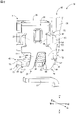
- FIG. 1 is a perspective view showing the terminal module of the embodiment.
- FIG. 2 is a perspective view showing the terminal module and the mating terminal member of the embodiment.
- FIG. 3 is a front view showing the terminal module of the embodiment;
- FIG. 4 is a right side view showing the terminal module of the embodiment.
- FIG. 5 is a bottom view showing the terminal module of the embodiment.
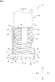
- 6 is a sectional view taken along line VI-VI in FIG. 3.
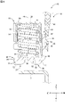
- FIG. FIG. 7 is a perspective view showing the terminal module and the mating terminal member of the embodiment.
- FIG. 8 is a longitudinal sectional view showing the terminal module and the mating terminal member of the embodiment.
- An object of the present disclosure is to provide a terminal module that can improve durability.
- a terminal module of the present disclosure is a terminal module electrically connectable to a counterpart terminal member, comprising an elastically deformable coil spring, a case accommodating the coil spring, and a terminal member attached to the case. and wherein the coil spring has a first end and a second end located opposite the first end, and the case is attached to the first end of the coil spring.
- the terminal member includes the pair of a first terminal attached to a sidewall and movable relative to the pair of sidewalls; and a flexible conductor electrically connected to the first terminal, each of the pair of sidewalls comprising: a side wall base connected to the ceiling wall, a first dividing wall connected to the side wall base, and a second dividing wall connected to the side wall base and separated from the first dividing wall,
- the first terminal has a joint portion to which the flexible conductor is joined, a first surface pressed against the second end portion of the coil spring, and a second surface arranged opposite to the first surface.
- first dividing wall portion has a first terminal receiving portion capable of receiving the first terminal pressed by the coil spring; and the second dividing wall portion and a second terminal receiving portion capable of receiving the first terminal pressed by the coil spring, and the joint portion is positioned outside the case when viewed from the direction in which the pair of side walls face each other.
- the first terminal is reversibly reversible between a first position and a second position different from the first position; is pressed by the coil spring, the guided portion is arranged between the first dividing wall portion and the second dividing wall portion, and the second engaging portion is the second It is engaged with a terminal receiving portion, and the first engaging portion is engaged with the first terminal receiving portion.
- the joint where the flexible conductor is joined to the first terminal is arranged outside the case when viewed from the direction in which the pair of side walls of the case face each other. Therefore, when the flexible conductor swings due to vibration or the like during transportation of the terminal module, it is possible to prevent the flexible conductor from coming into contact with the case, compared to the case where the joint portion is arranged inside the case. Therefore, the durability of the terminal module can be improved.
- the first terminal has a first portion that contacts the second end of the coil spring and a second portion that continues from the first portion and extends toward the ceiling wall side of the case. and, preferably, the joint portion is arranged on the second surface of the second portion and is closer to the ceiling wall than the second engaging portion.
- the flexible conductor is joined to the second surface of the second portion.
- the second surface of the second portion is the surface opposite to the first surface of the second portion facing the case. Therefore, the flexible conductor is further away from the case than when the flexible conductor is bonded to the first surface. Therefore, the contact of the flexible conductor with the case can be suppressed compared to the case where the flexible conductor is joined to the first surface of the second portion facing the case. As a result, the durability of the terminal module can be improved.
- the first terminal has a pair of side surfaces at least partially opposed to the pair of side walls of the case, and the guided portion protrudes from the pair of side surfaces, It is preferable that the portion protrudes from the pair of side surfaces, and the second engaging portion protrudes from the pair of side surfaces.
- the guided portion, the first engaging portion, and the second engaging portion protrude from a surface different from the second surface to which the flexible conductor is joined. Therefore, it is possible to prevent the flexible conductor from contacting the guided portion, the first engaging portion, and the second engaging portion. Therefore, the durability of the terminal module can be improved.
- the second surface of the second portion has a terminal slanted portion that is slanted toward the first surface toward the opposite side of the first portion, and the terminal slanted portion is the joint portion. preferably closer to the ceiling wall than
- the terminal inclined portion is provided on the ceiling wall side of the joint portion of the first terminal. Since the flexible conductor swings when the terminal module vibrates, the portion closer to the ceiling wall than the joint portion of the first terminal may come into repeated contact with the flexible conductor. Therefore, it is possible to suppress wear of the flexible conductor compared to the case where the first terminal is not provided with the terminal inclined portion. Therefore, the durability of the terminal module can be improved.
- the first terminal has a first terminal end portion arranged closer to the guided portion than the second engaging portion, and a second terminal end portion arranged opposite to the first terminal end. and a terminal end portion, wherein the terminal inclined portion is preferably located at the second terminal end portion.
- the terminal inclined portion is provided at the second terminal end portion, which is a part of the portion closer to the ceiling wall than the joint portion of the first terminal. Therefore, the wear of the flexible conductor can be suppressed as compared with the case where the terminal inclined portion is not provided. Therefore, the durability of the terminal module can be improved.
- the first dividing wall includes a first base connected to the side wall base, a first extension extending from the first base toward the opposite side of the second dividing wall, and the first terminal. and a first inclined portion contactable with the portion to be guided, wherein the first inclined portion is a surface facing the portion to be guided, and the second inclined portion faces the opposite side of the ceiling wall.
- the first terminal in the first position is inclined away from the dividing wall side, and the second surface is pressed by the mating terminal member to take the second position;
- the position of the portion to be guided at the second position is closer to the ceiling wall and further from the first extension portion than the position of the portion to be guided at the first position. It is preferable that the position of the portion to be guided at the second position is closer to the ceiling wall and further from the first extending portion than the position of the portion to be guided at the first position.
- the position of the guided portion of the first terminal at the second position is farther from the first extending portion than the position of the guided portion at the first position. That is, as the first terminal moves from the first position toward the second position, the joint where the flexible conductor is joined to the first terminal moves away from the case. Therefore, it is possible to prevent the flexible conductor from coming into contact with the case. Therefore, the durability of the terminal module can be improved.
- the terminal module 10 is electrically connectable with a mating terminal member 12 .
- the terminal module 10 and the mating terminal member 12 are used, for example, to electrically connect a plurality of in-vehicle devices (not shown).
- the terminal module 10 is held by, for example, a connector housing (not shown).
- the terminal module 10 is attached to vehicle-mounted equipment via a connector housing, for example.
- Vehicle-mounted devices include, for example, battery packs, inverters, and motors.
- the terminal module 10 includes a coil spring 14 , a case 16 that accommodates the coil spring 14 , and terminal members 18 attached to the case 16 .
- the terminal member 18 includes a first terminal 46 electrically connected to the mating terminal member 12, a second terminal 48 electrically connected to an external device (not shown), and a first terminal 46. and a flexible conductor 50 electrically connecting between and the second terminal 48 .
- the first terminal 46 is attached to the case 16 .
- the coil spring 14 is an example of an elastic member that can be elastically deformed.
- a metal material can be used.
- the coil spring 14 is formed, for example, by winding a wire material around a central axis 14c.
- the coil spring 14 has a first end 14a and a second end 14b.
- the first end 14 a is the axial end of the coil spring 14 .
- the second end 14b is the end opposite to the first end 14a in the axial direction. That is, the second end portion 14b is arranged on the opposite side of the first end portion 14a in the axial direction.
- the first end portion 14a and the second end portion 14b are arranged along the axial direction of the coil spring.
- the coil spring 14 is elastically deformable along the axial direction of the coil spring 14 .
- the coil spring 14 can expand and contract along the axial direction of the coil spring 14 .
- the first end 14a is in contact with the case 16.
- the second end 14b is in contact with the first terminal 46.
- the coil spring 14 is held between the case 16 and the first terminal 46 .
- the coil spring 14 sandwiched between the case 16 and the first terminal 46 is shorter than the natural length of the coil spring 14 . That is, the coil spring 14 sandwiched between the case 16 and the first terminal 46 is axially compressed. Therefore, the coil spring 14 presses the first terminal 46 while pressing the case 16 .
- a metal material such as stainless steel can be used.
- the case 16 is formed into a predetermined shape by, for example, press working.
- the case 16 has a ceiling wall 20 and a pair of side walls 22, 22 extending from the ceiling wall 20.
- the ceiling wall 20 has, for example, a rectangular shape.
- Ceiling wall 20 is in contact with first end 14 a of coil spring 14 .
- a pair of side walls 22 , 22 extend from the ceiling wall 20 toward the second end 14 b of the coil spring 14 .
- the pair of side walls 22 , 22 extend, for example, along the axial direction of the coil spring 14 .
- a pair of side walls 22, 22 are opposed to each other.
- the case 16 is open on the side opposite to the ceiling wall 20 in the axial direction of the coil spring 14 .
- a first terminal 46 is attached to the pair of side walls 22 , 22 .
- each of the pair of side walls 22, 22 includes a side wall base portion 24 that continues to the ceiling wall 20, a first dividing wall portion 26 that connects to the side wall base portion 24, and a first dividing wall portion that continues to the side wall base portion 24. and a second dividing wall portion 28 spaced apart from the portion 26 .
- the side wall base 24 has, for example, a rectangular shape.
- the first dividing wall portion 26 extends from the side wall base portion 24 toward the second end portion 14 b of the coil spring 14 .
- the second dividing wall portion 28 extends from the side wall base portion 24 toward the second end portion 14 b of the coil spring 14 .
- the first dividing wall portion 26 is separated from the second dividing wall portion 28 in a direction perpendicular to the axial direction of the coil spring 14 and the facing direction of the pair of side walls 22 , 22 .
- the axial direction of the coil spring 14 will be referred to as the vertical direction.
- the facing direction of the pair of side walls 22, 22 is called the left-right direction.
- a direction orthogonal to the axial direction of the coil spring 14 and the opposing direction of the pair of side walls 22, 22 is referred to as the front-rear direction.
- the side of the first end portion 14a is referred to as the upper side
- the side of the second end portion 14b is referred to as the lower side.
- the side of the first dividing wall portion 26 is called the front side
- the side of the second dividing wall portion 28 is called the rear side.
- the first dividing wall portion 26 extends downward from the lower end of the side wall base portion 24, for example.
- the second dividing wall portion 28 extends downward from the lower end of the side wall base portion 24, for example.
- the first dividing wall portion 26 is separated from the second dividing wall portion 28 in the front-rear direction.
- the first dividing wall portion 26 extends from, for example, the middle portion in the front-rear direction at the lower end of the side wall base portion 24 .
- the second partition wall portion 28 extends from, for example, the lower end of the side wall base portion 24 from the rear portion in the front-rear direction.
- the first dividing wall portion 26 is located forward of the second dividing wall portion 28 .
- a rear end surface of the first dividing wall portion 26 faces the second dividing wall portion 28 .
- the first dividing wall portion 26 is engageable with the first terminal 46 .
- the first dividing wall portion 26 includes a first base portion 30 connected to the side wall base portion 24 , a first extension portion 32 extending from the first base portion 30 toward the opposite side of the second dividing wall portion 28 , and a first terminal receiving portion 34 . , and a first inclined portion 36 facing the second dividing wall portion 28 .
- the first base portion 30 extends downward from the lower end of the side wall base portion 24 .
- the first base 30 extends forward as it goes downward as a whole.
- the first base 30 includes, for example, a front end that slopes forward as it goes downward.
- the first base portion 30 is located forward of the second dividing wall portion 28 .
- a rear end surface of the first base portion 30 faces, for example, the second dividing wall portion 28 .
- the first extending portion 32 extends forward from the first base portion 30 .
- the first extending portion 32 extends forward from the lower end of the first base portion 30, for example.
- the first extension 32 is, for example, engageable with the first terminal 46 .
- the upper end of the first extension portion 32 can be engaged with the first terminal 46, for example.
- the upper end surface of the first extension portion 32 can be engaged with the first terminal 46, for example.
- the first terminal receiving portion 34 can receive the first terminal 46 that is pressed downward by the coil spring 14 .
- the first terminal receiving portion 34 is engageable with the first terminal 46 that is pressed downward by the coil spring 14 .
- the first terminal receiving portion 34 is arranged on the first dividing wall portion 26 .
- the first terminal receiving portion 34 is arranged, for example, on the first extension portion 32 .
- the first terminal receiving portion 34 is, for example, a portion of the end surface of the first extending portion 32 facing the ceiling wall 20 .
- the first terminal receiving portion 34 is, for example, a portion of the upper end surface of the first extending portion 32 .
- the first inclined portion 36 is arranged at the rear end of the first dividing wall portion 26 .
- the first inclined portion 36 is, for example, part of the rear end surface of the first dividing wall portion 26 .
- the first inclined portion 36 is arranged, for example, at the rear end of the first base portion 30 .
- the first inclined portion 36 is, for example, part of the rear end surface of the first base portion 30 .
- the first inclined portion 36 is inclined away from the second dividing wall portion 28 side toward the opposite side of the ceiling wall 20 . That is, the first inclined portion 36 is inclined forward as it goes downward.
- the first inclined portion 36 is inclined away from the first extending portion 32 side toward the ceiling wall 20 side. That is, the first inclined portion 36 is inclined rearward as it goes upward.
- the first inclined portion 36 is, for example, continuously inclined.
- the first inclined portion 36 is, for example, linearly inclined.
- the first inclined portion 36 can contact the first terminal 46, for example.
- the first dividing wall portion 26 is provided on each of the pair of side walls 22,22.
- the pair of first dividing walls 26, 26 are, for example, parallel to each other.
- the pair of first bases 30, 30 are, for example, parallel to each other.
- the pair of first extensions 32, 32 are, for example, parallel to each other.
- the second dividing wall portion 28 includes a second base portion 38 connected to the side wall base portion 24 and a second extending portion 40 extending from the second base portion 38 toward the opposite side of the first dividing wall portion 26 . , a second terminal receiving portion 42 , and a second inclined portion 44 inclined so as to approach the first dividing wall portion 26 side toward the opposite side of the ceiling wall 20 .
- the second base portion 38 extends downward from the lower end of the side wall base portion 24 .
- the upper portion of the second base portion 38 extends downward, for example.
- the lower portion of the second base portion 38 extends, for example, so as to incline forward as it goes downward.
- the front end surface of the second base portion 38 faces at least a portion of the first terminal 46, for example.
- the front end surface of the second base portion 38 faces at least a portion of the first base portion 30, for example.
- the second extending portion 40 extends rearward from the second base portion 38 .
- the second extension portion 40 for example, straddles the upper portion and the lower portion of the second base portion 38 .
- the second extending portion 40 extends rearward from the side wall base portion 24, for example.
- the upper end of the second extension portion 40 extends in the front-rear direction.
- the upper end of the second extension portion 40 is, for example, closer to the ceiling wall 20 than the upper end of the first extension portion 32 is.
- the upper end surface of the second extension portion 40 is located above the upper end surface of the first extension portion 32, for example.
- the second extension 40 is engageable with, for example, a first terminal 46 .
- the upper end of the second extension part 40 can be engaged with the first terminal 46, for example.
- the upper end surface of the second extension portion 40 can be engaged with the first terminal 46, for example.
- the second terminal receiving portion 42 can receive the first terminal 46 pressed downward by the coil spring 14 .
- the second terminal receiving portion 42 is engageable with the first terminal 46 that is pressed downward by the coil spring 14 .
- the second terminal receiving portion 42 is arranged on the second dividing wall portion 28 .
- the second terminal receiving portion 42 is arranged, for example, on the second extension portion 40 .
- the second terminal receiving portion 42 is, for example, a portion of the end surface of the second extension portion 40 facing the ceiling wall 20 .
- the second terminal receiving portion 42 is, for example, part of the upper end surface of the second extending portion 40 .
- the second terminal receiving portion 42 is closer to the ceiling wall 20 than the first terminal receiving portion 34, for example.
- the second terminal receiving portion 42 is positioned, for example, above the first terminal receiving portion 34 .
- the second inclined portion 44 is arranged on the second dividing wall portion 28 .
- the second inclined portion 44 is arranged, for example, on the second extension portion 40 .
- the second inclined portion 44 is arranged, for example, at the rear end of the second extension portion 40 .
- the second inclined portion 44 is, for example, part of the rear end surface of the second extension portion 40 .
- the second inclined portion 44 is inclined so as to approach the first dividing wall portion 26 side toward the opposite side of the ceiling wall 20 .
- the second inclined portion 44 is inclined forward as it goes downward.
- the second dividing wall portion 28 is provided on each of the pair of side walls 22,22.
- the pair of second partition walls 28, 28 are, for example, parallel to each other.
- the pair of second bases 38, 38 are, for example, parallel to each other.
- the pair of second extensions 40, 40 are, for example, parallel to each other.
- First terminal 46 Metal materials such as copper, copper alloys, aluminum, and aluminum alloys can be used for the first terminals 46, for example.
- a plate material, for example, can be used for the first terminal 46 .
- the first terminal 46 is, for example, L-shaped when viewed from the left-right direction.
- the first terminal 46 is formed into a predetermined shape by, for example, press working.
- the first terminal 46 is attached to the pair of side walls 22, 22 of the case 16.
- the first terminal 46 is relatively movable with respect to the pair of side walls 22 , 22 .
- the first terminal 46 is pushed downward by the coil spring 14 so that the first terminal 46 assumes the first position in which it is engaged with the pair of side walls 22,22. can take.
- the first terminal 46 positioned at the first position is pressed upward by the mating terminal member 12, thereby causing the second terminal 46 positioned above the first position to move upward. position can be taken.
- the first terminal 46 arranged at the second position is pressed downward by the coil spring 14 .
- the first terminal 46 arranged at the second position can again take the first position by moving the mating terminal member 12 downward. That is, the first terminal 46 can reversibly take the first position and the second position according to the state of mechanical connection with the mating terminal member 12 .
- the first terminal 46 has a first portion 52 , a second portion 54 connected to the first portion 52 , a first surface 56 , and an opposite side of the first surface 56 . a second surface 58 facing upward, a pair of side surfaces 60 , 60 , a first terminal end 64 and a second terminal end 66 disposed opposite the first terminal end 64 .
- the first terminal 46 has a joint portion 55 to which the flexible conductor 50 is joined, a terminal inclined portion 62, a guided portion 68, a first engaging portion 70, and a second engaging portion 72.
- the first portion 52 extends, for example, in the front-rear direction.
- the first portion 52 contacts the second end 14 b of the coil spring 14 .
- the first portion 52 is, for example, engageable with the first dividing wall portion 26 .
- the first portion 52 is arranged above the first extension portion 32, for example. At least part of the first portion 52 is arranged inside the case 16 , for example. At least a portion of the first portion 52 is arranged between the pair of sidewalls 22, 22, for example.
- the second portion 54 is connected to the first portion 52.
- the second portion 54 extends, for example, from the first portion 52 toward the ceiling wall 20 side.
- the second portion 54 extends upward, for example.
- the second portion 54 intersects the first portion 52, for example.
- the second portion 54 is, for example, orthogonal to the first portion 52 . At least part of the second portion 54 is arranged outside the case 16 .
- First surface 56 straddles the first portion 52 and the second portion 54, for example.
- First surface 56 includes, for example, the top surface of first portion 52 and the front surface of second portion 54 .
- a first surface 56 of the first portion 52 contacts the second end 14 b of the coil spring 14 .
- the first surface 56 of the first portion 52 faces the ceiling wall 20 side of the case 16, for example.
- a first surface 56 of the second portion 54 faces, for example, the coil spring 14 side.
- the first surface 56 of the second portion 54 faces, for example, the side wall base 24 of the case 16 .
- the first surface 56 of the second portion 54 faces, for example, the first dividing wall portion 26 side of the case 16 .
- the second surface 58 is the surface opposite to the first surface 56 .
- the second surface 58 spans, for example, the first portion 52 and the second portion 54 .
- the second surface 58 includes, for example, the lower surface of the first portion 52 and the rear surface of the second portion 54 .
- a second surface 58 of the second portion 54 is, for example, joined to the flexible conductor 50 .
- a second surface 58 of the second portion 54 is arranged outside the case 16 , for example.
- the second surface 58 of the second portion 54 is arranged behind the case 16 , for example.
- At least part of the pair of side surfaces 60, 60 faces the pair of side walls 22, 22.
- One of the pair of side surfaces 60, 60 faces leftward, for example.
- the other of the pair of side surfaces 60, 60 faces rightward, for example.
- the pair of side surfaces 60 , 60 span, for example, the first portion 52 and the second portion 54 .
- the pair of side surfaces 60 , 60 includes, for example, the left end surface of the first portion 52 and the left end surface of the second portion 54 .
- the pair of side surfaces 60 , 60 includes, for example, the right end surface of the first portion 52 and the right end surface of the second portion 54 .
- At least part of the pair of side surfaces 60 , 60 in the first portion 52 faces the first dividing wall portion 26 , for example.
- At least part of the pair of side surfaces 60 , 60 in the first portion 52 faces the second dividing wall portion 28 , for example.
- the first terminal end portion 64 is, for example, an end portion located in front of the first portion 52 .
- the first terminal end 64 is, for example, the front end of the first terminal 46 .
- the first terminal end 64 is, for example, the front end of the first portion 52 of the first terminal 46 .
- the second terminal end portion 66 is an end portion located on the opposite side of the first terminal end portion 64 .
- the second terminal end portion 66 is, for example, an end portion located on the opposite side of the first terminal end portion 64 in the extending direction of the first terminal 46 .
- the second terminal end 66 is, for example, the upper end of the second portion 54 of the first terminal 46 .
- the second terminal end 66 is positioned above the first terminal end 64, for example.
- the guided portion 68 protrudes from the pair of side surfaces 60 , 60 of the first terminal 46 .
- the guided portion 68 protrudes from each of the pair of side surfaces 60, 60, for example.
- the guided portion 68 projects leftward from one of the pair of side surfaces 60, 60, for example.
- the guided portion 68 protrudes rightward from the other of the pair of side surfaces 60, 60, for example.
- the guided portion 68 protrudes in the horizontal direction beyond the first dividing wall portion 26 when viewed in the vertical direction.
- the guided portion 68 protrudes in the horizontal direction beyond the second partition wall portion 28 when viewed in the vertical direction.
- the guided portion 68 is arranged on the first portion 52 of the first terminal 46, for example.
- the guided portion 68 is arranged, for example, between the first terminal end portion 64 and the second terminal end portion 66 .
- the guided portion 68 is arranged, for example, between the first engaging portion 70 and the second engaging portion 72 in the front-rear direction.
- the guided portion 68 is arranged, for example, between the first dividing wall portion 26 and the second dividing wall portion 28 in the front-rear direction.
- the guided portion 68 faces, for example, the rear end surface of the first dividing wall portion 26 .
- the guided portion 68 faces, for example, the first inclined portion 36 .
- the guided portion 68 can come into contact with the first inclined portion 36, for example.
- the guided portion 68 faces, for example, the front end surface of the second dividing wall portion 28 .
- the first engaging portion 70 can be received by the first terminal receiving portion 34 when the first terminal 46 is pressed downward by the coil spring 14 .
- the first engaging portion 70 can engage with the first terminal receiving portion 34 when the first terminal 46 is pressed downward by the coil spring 14 . That is, when the first terminal 46 takes the first position, the first engaging portion 70 is engaged with the first terminal receiving portion 34 .
- the first engaging portion 70 protrudes from the pair of side surfaces 60, 60 of the first terminal 46, for example.
- the first engaging portion 70 protrudes from each of the pair of side surfaces 60, 60, for example.
- the first engaging portion 70 protrudes leftward from one of the pair of side surfaces 60 , 60 , for example.
- the first engaging portion 70 protrudes rightward from the other of the pair of side surfaces 60, 60, for example.
- the first engaging portion 70 protrudes in the horizontal direction from the side wall 22 when viewed from the vertical direction, for example.
- the first engaging portion 70 protrudes in the left-right direction, for example, more than the first dividing wall portion 26 .
- the first engaging portion 70 protrudes in the horizontal direction more than the first extending portion 32 when viewed in the vertical direction.
- the first engaging portion 70 is arranged at the first portion 52 of the first terminal 46, for example.
- the first engaging portion 70 is arranged, for example, at the first terminal end portion 64 .
- the first engaging portion 70 is arranged, for example, in front of the guided portion 68 .
- the first engaging portion 70 is arranged forward of the second engaging portion 72, for example.
- the first engaging portion 70 is arranged forward of the first base portion 30, for example.
- the first engaging portion 70 is arranged above the first extending portion 32, for example.
- the first engaging portion 70 is, for example, shorter than the first extending portion 32 in the front-rear direction.
- the second engaging portion 72 can be received by the second terminal receiving portion 42 when the first terminal 46 is pressed downward by the coil spring 14 .
- the second engaging portion 72 can engage with the second terminal receiving portion 42 when the first terminal 46 is pressed downward by the coil spring 14 . That is, the second engaging portion 72 is engaged with the second terminal receiving portion 42 when the first terminal 46 takes the first position.
- the second engaging portion 72 protrudes from the pair of side surfaces 60 , 60 of the first terminal 46 .
- the second engaging portion 72 protrudes from each of the pair of side surfaces 60, 60, for example.
- the second engaging portion 72 protrudes leftward from one of the pair of side surfaces 60, 60, for example.
- the second engaging portion 72 protrudes rightward from the other of the pair of side surfaces 60, 60, for example.
- the second engaging portion 72 protrudes in the left-right direction from the side wall 22 when viewed from the top-bottom direction, for example.
- the second engaging portion 72 protrudes in the horizontal direction beyond the second dividing wall portion 28 when viewed in the vertical direction.
- the second engaging portion 72 protrudes in the horizontal direction more than the second extending portion 40 when viewed in the vertical direction.
- the second engaging portion 72 is arranged on the second portion 54 of the first terminal 46, for example.
- the second engaging portion 72 is arranged, for example, between the guided portion 68 and the second terminal end portion 66 in the extending direction of the first terminal 46 .
- the second engaging portion 72 is arranged above the first engaging portion 70, for example.
- the second engaging portion 72 is arranged below the joint portion 55, for example.
- the second engaging portion 72 is arranged, for example, behind the second base portion 38 .
- the second engaging portion 72 is arranged above the second extending portion 40, for example.
- the joint portion 55 is a portion of the first terminal 46 to which the flexible conductor 50 is joined.
- the joint portion 55 is arranged, for example, on the second surface 58 of the second portion 54 .
- the joint portion 55 is arranged, for example, between the second terminal end portion 66 and the second engaging portion 72 .
- the joint portion 55 is located closer to the ceiling wall 20 of the case 16 than the second engaging portion 72 is, for example.
- the joint portion 55 is arranged above the second engaging portion 72, for example.
- the joint portion 55 is arranged outside the case 16 when viewed from the direction in which the pair of side walls 22 , 22 of the case 16 face each other.
- the joint portion 55 is arranged, for example, behind the case 16 when viewed in the left-right direction.
- the joint portion 55 is arranged, for example, behind the side wall base portion 24 of the case 16 when viewed in the left-right direction.
- the terminal inclined portion 62 is arranged on the second surface 58 of the second portion 54 .
- the terminal sloped portion 62 slopes toward the first surface 56 toward the opposite side of the first portion 52 in the extending direction of the first terminal 46 .
- the terminal inclined portion 62 is arranged closer to the ceiling wall 20 than the joint portion 55, for example.
- the terminal inclined portion 62 is arranged closer to the second terminal end portion 66 than the joint portion 55 is.
- the terminal inclined portion 62 is arranged above the joint portion 55, for example.
- the terminal ramp 62 is located, for example, at a second terminal end 66 .
- the terminal inclined portion 62 can face the flexible conductor 50 in the front-rear direction.
- the second terminal 48 can use, for example, a metal material.
- the second terminal 48 is, for example, plate-shaped.
- the second terminal 48 is formed into a predetermined shape by, for example, press working.
- a flexible conductor 50 is joined to one end of the second terminal 48 .
- the other end of the second terminal 48 can be electrically connected to an external device (not shown).
- the second terminal 48 is held at a position above the first terminal 46 by, for example, a housing (not shown).
- the flexible conductor 50 is a flexible conductor.
- the flexible conductor 50 is a conductor that is more flexible than the first terminal 46 .
- the flexible conductor 50 is a conductor that is more flexible than the second terminal 48 .
- the flexible conductor 50 is, for example, repeatedly deformable.
- the flexible conductor 50 is joined to the first terminal 46 and the second terminal 48 .
- Flexible conductor 50 is joined to first terminal 46 and second terminal 48 by known techniques such as welding.
- Flexible conductor 50 is electrically connected to first terminal 46 .
- the flexible conductor 50 is electrically connected with the second terminal 48 .
- the flexible conductor 50 is, for example, a braided member in which a plurality of metal wires are woven.
- the braided member is, for example, braided into a tubular shape.
- the outer peripheral surface of the braided member is joined to, for example, a first terminal 46 and a second terminal 48 .
- a metal material can be used.
- a plate material for example, can be used for the counterpart terminal member 12 .
- the mating terminal member 12 has, for example, an L shape.
- the mating terminal member 12 is formed into a predetermined shape by, for example, press working.
- the mating terminal member 12 can be electrically connected to the first terminal 46 by contacting the first terminal 46 .
- the mating terminal member 12 rubs against the second surface 58 of the first terminal 46 when the first terminal 46 moves from the first position to the second position.
- first terminal 46 can assume a first position.
- first terminal 46 can assume a second position.
- the first terminal 46 can reversibly take the first position and the second position according to the state of electrical connection with the counterpart terminal member 12, for example.
- the first terminal 46 assumes a first position, for example, prior to being electrically connected to the mating terminal member 12 .
- the first terminal 46 assumes the second position, for example, when electrically connected to the mating terminal member 12 .
- the first terminal 46 assumes the first position, for example, when the electrical connection with the mating terminal member 12 is broken.
- the first terminal 46 can reversibly take the first position and the second position according to the state of mechanical connection with the mating terminal member 12, for example.
- the first terminal 46 assumes the first position, for example, before being mechanically connected to the mating terminal member 12 .
- the first terminal 46 assumes the second position, for example, when mechanically connected to the mating terminal member 12 .
- the first terminal 46 assumes the first position, for example, when the mechanical connection with the mating terminal member 12 is broken.
- the first terminal 46 can take the first position by being pressed downward by the coil spring 14 .
- the guided portion 68 at the first position is arranged between the first dividing wall portion 26 and the second dividing wall portion 28 .
- the first engaging portion 70 of the first terminal 46 is engaged with the first terminal receiving portion 34 .
- the first engaging portion 70 engages with, for example, the first dividing wall portion 26 .
- the first engagement portion 70 engages with the first extension portion 32, for example.
- the second engaging portion 72 of the first terminal 46 is engaged with the second terminal receiving portion 42 .
- the second engaging portion 72 engages with, for example, the second dividing wall portion 28 .
- the second engaging portion 72 engages with, for example, the second extension portion 40 . Therefore, at the first position, the first terminal 46 is sandwiched between the case 16 and the coil spring 14, for example.
- the joint 55 is arranged outside the case 16 when viewed from the direction in which the pair of side walls 22, 22 of the case 16 face each other.
- the joint portion 55 is arranged behind the case 16 when viewed in the left-right direction.
- the joint portion 55 is arranged behind the side wall base portion 24 of the case 16 when viewed in the left-right direction.
- the first terminal 46 at the first position is pressed toward the ceiling wall 20 by the mating terminal member 12 so that the first terminal 46 can take the second position. can.
- the guided portion 68 of the first terminal 46 slides along the first inclined portion 36 . That is, the guided portion 68 is guided by the first inclined portion 36 . Therefore, when the first terminal 46 moves from the first position to the second position, the moving direction of the first terminal 46 is restricted by the first inclined portion 36 .
- the first inclined portion 36 is inclined away from the first extending portion 32 side toward the ceiling wall 20 side.
- the guided portion 68 moves away from the first extending portion 32 as it approaches the ceiling wall 20 side. It is guided by 1 ramp 36 . That is, the guided portion 68 is guided rearward as it goes upward by the first inclined portion 36 . Therefore, the guided portion 68 of the first terminal 46 at the second position is located above and behind the guided portion 68 of the first terminal 46 at the first position. That is, the first terminal 46 is pushed upward by the mating terminal member 12 and moves upward and rearward.
- the guided portion 68 protrudes in the left-right direction beyond the first dividing wall portion 26 when viewed in the vertical direction. Furthermore, the guided portion 68 protrudes in the left-right direction beyond the second partition wall portion 28 when viewed in the vertical direction. Therefore, compared to the case where the first terminal 46 has only one guided portion 68, it is possible to prevent the first terminal 46 from tilting when the first terminal 46 moves from the first position to the second position. Therefore, the contact area between the first terminal 46 and the counterpart terminal member 12 can be suppressed from decreasing, and the contact resistance between the first terminal 46 and the counterpart terminal member 12 can be suppressed from increasing. As a result, heat generation of the terminal module 10 can be suppressed.
- the first engaging portion 70 of the first terminal 46 is separated from the first terminal receiving portion 34 . That is, at the second position, the first engaging portion 70 is disengaged from the first terminal receiving portion 34 .
- the second engaging portion 72 of the first terminal 46 is separated from the second terminal receiving portion 42 . That is, at the second position, the second engaging portion 72 is disengaged from the second terminal receiving portion 42 . Therefore, at the second position, the first terminal 46 is sandwiched between, for example, the coil spring 14 and the mating terminal member 12 .
- the joint portion 55 of the first terminal 46 to which the flexible conductor 50 is joined is positioned outside the case 16 when viewed from the left-right direction. That is, the joint portion 55 is positioned rearward of the case 16 . As shown in FIGS. 6 and 8, the joint 55 at the second position is farther from the case 16 than the joint 55 at the first position. That is, the joint portion 55 at the second position is located rearward from the joint portion 55 at the first position.
- the first terminal 46 at the second position is pressed downward by the coil spring 14 .
- the first terminal 46 at the second position is supported from below by the counterpart terminal member 12 . That is, the first terminal 46 at the second position is restrained from moving downward by the counterpart terminal member 12 . Accordingly, when the mating terminal member 12 is moved downward, the first terminal 46 moves downward from the second position.
- the first terminal 46 engages with the case 16 and stops moving downward. More specifically, the first engaging portion 70 of the first terminal 46 engages the first terminal receiving portion 34 of the case 16 . The second engaging portion 72 of the first terminal 46 engages with the second terminal receiving portion 42 of the case 16 . That is, the first terminal 46 assumes the first position again. Therefore, the first terminal 46 can reversibly take the first position and the second position.
- the flexible conductor 50 is deformable in accordance with the movement of the first terminal 46 when the first terminal 46 reversibly moves between the first position and the second position. That is, the deformation of the flexible conductor 50 allows the first terminal 46 to reversibly take the first position and the second position.
- the flexible conductor 50 is pushed by the first terminal 46 and bends, for example, when the first terminal 46 moves from the first position to the second position. Therefore, the terminal module 10 can accommodate a shortened distance between the first terminal 46 and the second terminal 48 .
- the flexible conductor 50 is stretched by being pulled by the first terminal 46, for example, when the first terminal 46 moves from the second position to the first position. Therefore, the terminal module 10 can accommodate an increase in the distance between the first terminals 46 and the second terminals 48 .
- the terminal module 10 is assembled, for example, as follows. First, a case 16 having a predetermined shape is prepared. The flexible conductor 50 is then joined to the first terminal 46 and the second terminal 48 to prepare the terminal member 18 . Next, the coil spring 14 is housed inside the case 16 . Next, the first engaging portion 70 of the first terminal 46 is hooked on the upper end surface of the first extending portion 32 of the first dividing wall portion 26 . In this state, the first engaging portion 70 is positioned above the first extending portion 32 . The guided portion 68 is located below the first extension portion 32 .
- the first terminal 46 is pushed into the ceiling wall 20 side of the case 16 and rotated with respect to the case 16 .
- the rotation direction of the first terminal 46 is, for example, counterclockwise in FIG.
- the first terminal 46 rotates with respect to the case 16 , for example, around the first engaging portion 70 .
- the coil spring 14 housed in the case 16 is vertically compressed by the first terminal 46 .
- the guided portion 68 of the first terminal 46 enters between the first dividing wall portion 26 and the second dividing wall portion 28 .
- the second engaging portion 72 of the first terminal 46 wraps around above the second terminal receiving portion 42 of the second extension portion 40 .
- the second inclined portion 44 provided in the second dividing wall portion 28 has an inclined shape, the second engaging portion 72 easily wraps around the second terminal receiving portion 42 . That is, the second inclined portion 44 prevents the second engaging portion 72 from being caught on the second dividing wall portion 28 .
- the ceiling wall 20 and the first terminal 46 are separated from each other in the vertical direction.
- the distance between them is shorter than the natural length of the coil spring 14 . That is, in this state, the coil spring 14 is vertically compressed by the ceiling wall 20 and the first terminal 46 . In this state, the coil spring 14 generates a restoring force in the vertical direction.
- the second end 14b of the spring 14 presses downward. As a result, the first engaging portion 70 of the first terminal 46 engages the first terminal receiving portion 34 from above.
- the second engaging portion 72 of the first terminal 46 engages the second terminal receiving portion 42 from above. That is, the first engaging portion 70 and the second engaging portion 72 are received by the first terminal receiving portion 34 and the second terminal receiving portion 42, respectively.
- the terminal module 10 is completed. Note that the first terminals 46 of the assembled terminal module 10 are in the first position.
- the distance between the ceiling wall 20 and the first portion 52 of the first terminal 46 is shorter than the natural length of the coil spring 14. Therefore, the first engaging portion 70 is pressed against the first terminal receiving portion 34 by the coil spring 14 .
- the second engaging portion 72 is pressed against the second terminal receiving portion 42 by the coil spring 14 .
- the engagement state between the case 16 and the first terminal 46 is maintained by the coil spring 14 . That is, the first terminals 46 of the terminal module 10 can maintain the first position until they are connected to the mating terminal member 12, for example.
- the terminal module 10 may be completed by connecting the flexible conductor 50 and the second terminal 48 to the first terminal 46 after assembling the first terminal 46 to the case 16 .
- the joint portion 55 of the first terminal 46 to which the flexible conductor 50 is joined is positioned outside the case 16 when viewed from the direction in which the pair of side walls 22, 22 of the case 16 face each other. ing.
- the flexible conductors 50 can be prevented from coming into contact with the case 16 as compared with the case where the joint portion 55 is positioned inside the case 16 . Therefore, it is possible to prevent the flexible conductor 50 from swinging and coming into contact with the case 16 when the terminal module 10 is transported or when the vehicle on which the terminal module 10 is mounted runs. Therefore, the durability of the terminal module 10 can be improved.
- the joint portion 55 of the first terminal 46 to which the flexible conductor 50 is joined is arranged on the second surface 58 of the second portion 54 .
- a second surface 58 of the second portion 54 faces away from the case 16 .
- the joint portion 55 is arranged closer to the ceiling wall 20 than the second engaging portion 72 for attaching the first terminal 46 to the case 16 . Therefore, contact of the flexible conductor 50 with the case 16 can be suppressed compared to the case where the joint portion 55 is arranged on the first surface 56 of the second portion 54 .
- the flexible conductor 50 is arranged above the second engaging portion 72, contact of the flexible conductor 50 with the second engaging portion 72 can be suppressed. Therefore, the durability of the terminal module 10 can be improved.
- the guided portion 68 , the first engaging portion 70 and the second engaging portion 72 protrude from the pair of side surfaces 60 , 60 of the first terminal 46 . That is, the guided portion 68, the first engaging portion 70, and the second engaging portion 72 are provided on a surface different from the second surface 58 on which the joint portion 55 is provided. Therefore, the flexible conductor 50 connected to the second surface 58 of the second portion 54 can be prevented from coming into contact with the guided portion 68 , the first engaging portion 70 and the second engaging portion 72 . Therefore, the durability of the terminal module 10 can be improved.
- the second surface 58 of the second portion 54 has the first inclined portion 36 closer to the ceiling wall 20 than the joint portion 55 is. That is, the first inclined portion 36 is positioned above the joint portion 55 . Therefore, it is possible to prevent the flexible conductor 50 from contacting the corners of the upper ends of the first terminals 46 . Therefore, the durability of the terminal module 10 can be improved.
- the first angled portion 36 is located at the second terminal end 66 of the second portion 54 of the first terminal 46 .
- the second terminal end portion 66 corresponds to the upper end portion of the first terminal 46 . That is, the second terminal end portion 66 is arranged above the joint portion 55 . Therefore, it is possible to prevent the flexible conductor 50 from contacting the corners of the upper ends of the first terminals 46 . Therefore, the durability of the terminal module 10 can be improved.
- the position of the guided portion 68 of the first terminal 46 at the second position is closer to the ceiling wall 20 than the position of the guided portion 68 of the first terminal 46 at the first position, is seperated. That is, the first terminal 46 moves upward and rearward by connecting with the mating terminal member 12 . Accordingly, the joint portion 55 at the second position is further away from the case 16 in the front-rear direction than the joint portion 55 at the first position. Furthermore, the joint 55 at the second position is closer to the ceiling wall 20 than the joint 55 at the first position. Therefore, even when the first terminal 46 is connected to the counterpart terminal member 12, it is possible to prevent the flexible conductor 50 from contacting the case 16, as compared with the case where the first terminal 46 moves only upward. Therefore, the durability of the terminal module 10 can be improved.
- the above embodiment can be implemented with the following modifications.
- the above embodiments and the following modifications can be combined with each other within a technically consistent range.
- the flexible conductor 50 may not be a braided member.
- the flexible conductor 50 has flexibility, so long as it can be repeatedly deformed according to the movement of the first terminal 46 .
- the flexible conductor 50 may be, for example, a twisted wire in which a plurality of metal wires are twisted, or an insulated wire having a twisted wire as a core wire.
- the flexible conductor 50 may be, for example, a thin-plate laminated conductor in which a plurality of thin-plate conductors are stacked.
- the first terminal 46 may not have the first portion 52 and the second portion 54 . That is, the first terminal 46 may, for example, omit the second portion 54 and have a flat plate shape.
- the joint portion 55 may be arranged outside the case 16 . That is, the flexible conductor 50 may be joined to a portion other than the second surface 58 of the second portion 54 .
- the joint portion 55 may be joined to the first surface 56 of the first portion 52, for example.
- the joint portion 55 may be farther from the ceiling wall 20 than the second engaging portion 72, for example.
- the terminal inclined portion 62 may be omitted.
- the terminal inclined portion 62 may be provided at a portion other than the second terminal end portion 66 .
- One or three or more guided portions 68 may be provided.
- the guided portion 68 may protrude from a portion other than the side surface 60 .
- the guided portion 68 may be arranged other than the first portion 52 .
- the guided portion 68 may be arranged other than between the first engaging portion 70 and the second engaging portion 72 in the front-rear direction.
- the plurality of guided portions 68 may be provided at different positions in the front-rear direction.
- first engaging portions 70 may be provided.
- the first engaging portion 70 may protrude from other than the side surface 60 .
- the 1st engagement part 70 may be arrange
- One second engaging portion 72 or three or more second engaging portions 72 may be provided.
- the second engaging portion 72 may be arranged outside the second portion 54 .
- the plurality of second engaging portions 72 may be provided at different positions in the front-rear direction.
- the mating terminal member 12 may have a projection projecting toward the first terminal 46 .
- the first terminal 46 may have a projecting portion projecting toward the counterpart terminal member 12 .
- the pair of side walls 22, 22 may not be parallel to each other.
- the pair of first dividing walls 26 may not be parallel to each other.
- the pair of first bases 30 may not be parallel to each other.
- the pair of first extension portions 32 may not be parallel to each other.
- the pair of second dividing walls 28 may not be parallel to each other.
- the pair of second bases 38 may not be parallel to each other.
- the pair of second extensions 40 may not be parallel to each other.
- the first dividing wall portion 26 may extend from a portion other than the lower end of the intermediate portion of the side wall base portion 24 of the side wall 22 .
- the second dividing wall portion 28 may extend from a portion other than the lower end of the rear end of the side wall base portion 24 of the side wall 22 .
- the first extension portion 32 may extend from a portion other than the lower end of the first base portion 30 .
- the 1st extension part 32 may be abbreviate
- the first terminal receiving portion 34 does not have to be the upper end surface of the first extending portion 32 .
- the first terminal receiving portion 34 can be freely arranged on the first dividing wall portion 26 as long as it can engage with the first engaging portion 70 of the first terminal 46 that is pressed downward by the coil spring 14 .
- the second extension portion 40 may extend from a portion other than the lower end of the second base portion 38 .
- the second extension part 40 may be omitted.
- the second terminal receiving portion 42 does not have to be the upper end surface of the second extending portion 40 .
- the second terminal receiving portion 42 can be freely arranged on the second dividing wall portion 28 as long as it can engage with the second engaging portion 72 of the first terminal 46 that is pressed downward by the coil spring 14 .
- the first inclined portion 36 is arranged such that the guided portion 68 of the first terminal 46 at the second position is located above and behind the guided portion 68 of the first terminal 46 at the first position. It is sufficient if the guided portion 68 of 46 can be guided. - The 1st inclination part 36 does not need to incline continuously. - The first inclined portion 36 does not have to be provided over the entire rear end surface of the first base portion 30 . The first inclined portion 36 may be provided, for example, only in a region that can come into contact with the guided portion 68 of the first terminal 46 . - The first inclined portion 36 does not have to be the rear end surface of the first base portion 30 . The first inclined portion 36 may be provided, for example, by bending a portion of the first base portion 30 by press working.
- the first inclined portion 36 may be omitted.
- a structure for guiding the guided portion 68 may be provided in a connector housing (not shown) that accommodates the terminal module 10 . That is, the structure for guiding the first terminals 46 from the first position to the second position when the first terminals 46 are pushed upward by the mating terminal member 12 is not necessarily provided in the terminal module 10 itself. It doesn't have to be.
- Terminal module 12
- Counterpart terminal member 14
- Coil spring 14a First end 14b Second end 14c Center shaft 16
- Case 18 Terminal member 20
- Ceiling wall 22
- Side wall 24
- Side wall base (base) 26
- First dividing wall portion 28
- Second dividing wall portion 30
- First base (first dividing wall side base) 32
- first extension (first partition side extension) 34
- first terminal receiving portion 36
- first inclined portion (first dividing wall side inclined portion) 38
- second base second dividing wall side base)
- Second terminal receiving portion 42
- Second terminal receiving portion 44
- Second inclined portion (second dividing wall side inclined portion) 46 48
- second terminal 50
- flexible conductor 52
- first portion 54
- second portion 55 joint portion
- first surface 58 second surface
- side surface 60
- terminal inclined portion 64
- first terminal end (first terminal side first end) 66
- second terminal end (first terminal side second end) 68
- Guided portion 70
- First engaging portion 72
Landscapes
- Connections Arranged To Contact A Plurality Of Conductors (AREA)
- Connection Or Junction Boxes (AREA)
- Connector Housings Or Holding Contact Members (AREA)
Priority Applications (3)
| Application Number | Priority Date | Filing Date | Title |
|---|---|---|---|
| US18/277,741 US12567693B2 (en) | 2021-03-04 | 2021-09-08 | Terminal module including coil spring and divided wall structure |
| JP2023503351A JP7529137B2 (ja) | 2021-03-04 | 2021-09-08 | 端子モジュール |
| CN202180091784.1A CN116746000A (zh) | 2021-03-04 | 2021-09-08 | 端子模块 |
Applications Claiming Priority (2)
| Application Number | Priority Date | Filing Date | Title |
|---|---|---|---|
| JP2021-034043 | 2021-03-04 | ||
| JP2021034043 | 2021-03-04 |
Publications (1)
| Publication Number | Publication Date |
|---|---|
| WO2022185574A1 true WO2022185574A1 (ja) | 2022-09-09 |
Family
ID=83155235
Family Applications (1)
| Application Number | Title | Priority Date | Filing Date |
|---|---|---|---|
| PCT/JP2021/032924 Ceased WO2022185574A1 (ja) | 2021-03-04 | 2021-09-08 | 端子モジュール |
Country Status (4)
| Country | Link |
|---|---|
| US (1) | US12567693B2 (https=) |
| JP (1) | JP7529137B2 (https=) |
| CN (1) | CN116746000A (https=) |
| WO (1) | WO2022185574A1 (https=) |
Cited By (1)
| Publication number | Priority date | Publication date | Assignee | Title |
|---|---|---|---|---|
| WO2025187422A1 (ja) * | 2024-03-05 | 2025-09-12 | 株式会社オートネットワーク技術研究所 | コネクタユニット |
Families Citing this family (1)
| Publication number | Priority date | Publication date | Assignee | Title |
|---|---|---|---|---|
| US20240128673A1 (en) * | 2021-03-04 | 2024-04-18 | Sumitomo Wiring Systems, Ltd. | Terminal module |
Citations (3)
| Publication number | Priority date | Publication date | Assignee | Title |
|---|---|---|---|---|
| WO2017073290A1 (ja) * | 2015-10-28 | 2017-05-04 | 株式会社オートネットワーク技術研究所 | 端子 |
| WO2018116964A1 (ja) * | 2016-12-21 | 2018-06-28 | 株式会社オートネットワーク技術研究所 | 端子モジュール及びコネクタ |
| JP2019200997A (ja) * | 2019-07-02 | 2019-11-21 | 日立金属株式会社 | 機器用配線集合体 |
Family Cites Families (6)
| Publication number | Priority date | Publication date | Assignee | Title |
|---|---|---|---|---|
| JP2014107114A (ja) * | 2012-11-27 | 2014-06-09 | Hosiden Corp | 部品モジュール及び相手側コネクタ並びに部品モジュールと相手側コネクタとの接続構造 |
| JP6116339B2 (ja) * | 2013-04-25 | 2017-04-19 | 矢崎総業株式会社 | 板状端子 |
| JP6500771B2 (ja) * | 2015-12-25 | 2019-04-17 | 株式会社オートネットワーク技術研究所 | コネクタ |
| WO2017163858A1 (ja) | 2016-03-24 | 2017-09-28 | 株式会社オートネットワーク技術研究所 | 端子モジュール |
| CN110114979A (zh) * | 2016-12-22 | 2019-08-09 | 株式会社村田制作所 | 高频开关以及通信装置 |
| JP6766752B2 (ja) | 2017-05-26 | 2020-10-14 | 株式会社オートネットワーク技術研究所 | 端子モジュール |
-
2021
- 2021-09-08 CN CN202180091784.1A patent/CN116746000A/zh active Pending
- 2021-09-08 JP JP2023503351A patent/JP7529137B2/ja active Active
- 2021-09-08 US US18/277,741 patent/US12567693B2/en active Active
- 2021-09-08 WO PCT/JP2021/032924 patent/WO2022185574A1/ja not_active Ceased
Patent Citations (3)
| Publication number | Priority date | Publication date | Assignee | Title |
|---|---|---|---|---|
| WO2017073290A1 (ja) * | 2015-10-28 | 2017-05-04 | 株式会社オートネットワーク技術研究所 | 端子 |
| WO2018116964A1 (ja) * | 2016-12-21 | 2018-06-28 | 株式会社オートネットワーク技術研究所 | 端子モジュール及びコネクタ |
| JP2019200997A (ja) * | 2019-07-02 | 2019-11-21 | 日立金属株式会社 | 機器用配線集合体 |
Cited By (1)
| Publication number | Priority date | Publication date | Assignee | Title |
|---|---|---|---|---|
| WO2025187422A1 (ja) * | 2024-03-05 | 2025-09-12 | 株式会社オートネットワーク技術研究所 | コネクタユニット |
Also Published As
| Publication number | Publication date |
|---|---|
| US20240136751A1 (en) | 2024-04-25 |
| US12567693B2 (en) | 2026-03-03 |
| CN116746000A (zh) | 2023-09-12 |
| JP7529137B2 (ja) | 2024-08-06 |
| US20240235088A9 (en) | 2024-07-11 |
| JPWO2022185574A1 (https=) | 2022-09-09 |
Similar Documents
| Publication | Publication Date | Title |
|---|---|---|
| US20210234296A1 (en) | Terminal module | |
| US9583869B2 (en) | Connector and electrical connection device | |
| US20150171546A1 (en) | Female terminal | |
| JP2018101556A (ja) | 端子モジュール及びコネクタ | |
| WO2022185574A1 (ja) | 端子モジュール | |
| WO2022259694A1 (ja) | 端子モジュール及びコネクタ | |
| JP7202937B2 (ja) | コネクタ及びコネクタ組立体 | |
| WO2022185573A1 (ja) | 端子モジュール | |
| WO2022185572A1 (ja) | 端子モジュール | |
| JP7384313B2 (ja) | コネクタ | |
| JP6282932B2 (ja) | コネクタ | |
| JP7439989B2 (ja) | コネクタ | |
| JP7384314B2 (ja) | コネクタ | |
| WO2022102698A1 (ja) | コネクタおよびコネクタ装置 | |
| JP6996601B2 (ja) | 端子モジュール、コネクタ、および嵌合構造 | |
| JP2020194716A (ja) | 端子付き電線、及び、ワイヤハーネス | |
| JP2023170120A (ja) | コネクタ及びコネクタ付きワイヤハーネス | |
| JP5652353B2 (ja) | ワイヤハーネス搭載用のジョイントコネクタ | |
| JP2022077958A (ja) | コネクタおよびコネクタ装置 | |
| JP2018106873A (ja) | コネクタ及び電気的接続装置 | |
| JP2012054190A (ja) | 電気コネクタ |
Legal Events
| Date | Code | Title | Description |
|---|---|---|---|
| 121 | Ep: the epo has been informed by wipo that ep was designated in this application |
Ref document number: 21928376 Country of ref document: EP Kind code of ref document: A1 |
|
| ENP | Entry into the national phase |
Ref document number: 2023503351 Country of ref document: JP Kind code of ref document: A |
|
| WWE | Wipo information: entry into national phase |
Ref document number: 202180091784.1 Country of ref document: CN |
|
| WWE | Wipo information: entry into national phase |
Ref document number: 18277741 Country of ref document: US |
|
| NENP | Non-entry into the national phase |
Ref country code: DE |
|
| 122 | Ep: pct application non-entry in european phase |
Ref document number: 21928376 Country of ref document: EP Kind code of ref document: A1 |
|
| WWG | Wipo information: grant in national office |
Ref document number: 18277741 Country of ref document: US |