WO2022185560A1 - Dispositif de présentation à détection de force - Google Patents
Dispositif de présentation à détection de force Download PDFInfo
- Publication number
- WO2022185560A1 WO2022185560A1 PCT/JP2021/025125 JP2021025125W WO2022185560A1 WO 2022185560 A1 WO2022185560 A1 WO 2022185560A1 JP 2021025125 W JP2021025125 W JP 2021025125W WO 2022185560 A1 WO2022185560 A1 WO 2022185560A1
- Authority
- WO
- WIPO (PCT)
- Prior art keywords
- base
- presentation device
- finger
- user
- movable part
- Prior art date
Links
- 230000035807 sensation Effects 0.000 claims description 8
- 239000000758 substrate Substances 0.000 claims description 8
- 210000003811 finger Anatomy 0.000 description 84
- 238000004891 communication Methods 0.000 description 7
- 210000003813 thumb Anatomy 0.000 description 6
- 238000010586 diagram Methods 0.000 description 5
- 238000012986 modification Methods 0.000 description 5
- 230000004048 modification Effects 0.000 description 5
- 238000001514 detection method Methods 0.000 description 4
- 238000012545 processing Methods 0.000 description 4
- 238000009434 installation Methods 0.000 description 3
- 238000012544 monitoring process Methods 0.000 description 3
- 230000009023 proprioceptive sensation Effects 0.000 description 2
- 230000006870 function Effects 0.000 description 1
- 238000005259 measurement Methods 0.000 description 1
- 238000000034 method Methods 0.000 description 1
- 230000015541 sensory perception of touch Effects 0.000 description 1
Images


Classifications
-
- G—PHYSICS
- G06—COMPUTING; CALCULATING OR COUNTING
- G06F—ELECTRIC DIGITAL DATA PROCESSING
- G06F3/00—Input arrangements for transferring data to be processed into a form capable of being handled by the computer; Output arrangements for transferring data from processing unit to output unit, e.g. interface arrangements
- G06F3/01—Input arrangements or combined input and output arrangements for interaction between user and computer
- G06F3/016—Input arrangements with force or tactile feedback as computer generated output to the user
-
- G—PHYSICS
- G06—COMPUTING; CALCULATING OR COUNTING
- G06F—ELECTRIC DIGITAL DATA PROCESSING
- G06F3/00—Input arrangements for transferring data to be processed into a form capable of being handled by the computer; Output arrangements for transferring data from processing unit to output unit, e.g. interface arrangements
- G06F3/01—Input arrangements or combined input and output arrangements for interaction between user and computer
- G06F3/03—Arrangements for converting the position or the displacement of a member into a coded form
- G06F3/033—Pointing devices displaced or positioned by the user, e.g. mice, trackballs, pens or joysticks; Accessories therefor
- G06F3/0346—Pointing devices displaced or positioned by the user, e.g. mice, trackballs, pens or joysticks; Accessories therefor with detection of the device orientation or free movement in a 3D space, e.g. 3D mice, 6-DOF [six degrees of freedom] pointers using gyroscopes, accelerometers or tilt-sensors
-
- G—PHYSICS
- G06—COMPUTING; CALCULATING OR COUNTING
- G06F—ELECTRIC DIGITAL DATA PROCESSING
- G06F3/00—Input arrangements for transferring data to be processed into a form capable of being handled by the computer; Output arrangements for transferring data from processing unit to output unit, e.g. interface arrangements
- G06F3/01—Input arrangements or combined input and output arrangements for interaction between user and computer
- G06F3/03—Arrangements for converting the position or the displacement of a member into a coded form
- G06F3/033—Pointing devices displaced or positioned by the user, e.g. mice, trackballs, pens or joysticks; Accessories therefor
- G06F3/0354—Pointing devices displaced or positioned by the user, e.g. mice, trackballs, pens or joysticks; Accessories therefor with detection of 2D relative movements between the device, or an operating part thereof, and a plane or surface, e.g. 2D mice, trackballs, pens or pucks
- G06F3/03545—Pens or stylus
Definitions
- the present invention relates to a device that is held by a user's hand and presents the user with a haptic sensation.
- Patent Document 1 the user inserts his or her index finger into a ring fixed to a base, holds the movable portion with the thumb, index finger, and middle finger, and moves the movable portion with respect to the base.
- a pen-type haptic presentation device that presents proprioception to a finger.
- an object of the present invention is to provide a haptic presentation device that is easy for users to use.
- a haptic presentation device is a movable part having a base to be gripped by a user's hand and a finger placement part for the user to place a fingertip while gripping the base. and a moving mechanism for moving the movable part with respect to the base.
- FIG. 4 is a diagram showing a state in which a user holds the haptic device.
- 1 is a side view of a force sense presentation device;
- FIG. It is a figure which shows the state which put the finger
- It is a figure which shows the moving mechanism which makes a movable part move relatively with respect to a base
- It is a figure which shows the example of a switch mechanism.
- FIG. 4 shows the functional block of a haptic device.
- FIG. 4 is a diagram showing an example of a pushing member;
- FIG. 4 is a diagram showing a state in which a user holds the haptic device.
- FIG. 4 is a diagram showing a state in which a user holds the haptic device.
- FIG. 1 is a side view of a force sense presentation device;
- FIG. It is a figure which shows the moving mechanism which carries out the relative rotational movement of a movable part with respect to a base
- FIG. 10 is a diagram showing the inclination of the support base frame when the haptic device is viewed from the front; It is a figure which shows the functional block of a haptic device. It is a figure which shows the modification of a moving mechanism. It is a figure which shows the modification of a moving mechanism. It is a figure which shows a wire direct-acting mechanism.
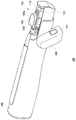
- FIG. 1 shows a state in which a user holds the haptic presentation device 1 of the first embodiment.
- FIG. 1(a) shows the haptic device 1 viewed from the front
- FIG. 1(b) shows the haptic device 1 viewed from the side.
- a haptic presentation device 1 includes a base 2 that is held by a user's hand, and a movable portion 3 that is relatively movable with respect to the base 2 .
- the haptic presentation device 1 is a pen-shaped haptic device, and the base 2 has two side surfaces arranged substantially parallel to each other.
- a user uses the force sense presentation device 1 in a state in which both sides of the base body 2 are held between the thumb and the middle finger and the index finger is placed on the movable part 3 .
- the haptic presentation device 1 is used, for example, as a virtual pen that ejects ink in a drawing application that draws pictures and letters on a whiteboard installed in a virtual space.
- the tip of the haptic device 1 corresponds to the pen tip of the virtual pen, and when the pen tip contacts a virtual object such as a whiteboard in the virtual space, the movable part 3 moves relative to the base 2.
- a haptic is presented to the user's index finger. By presenting the haptic, the user can recognize that he/she can start drawing pictures or characters.
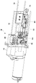
- FIG. 2 is a side view of the force sense presentation device 1.
- the side on which the movable part 3 is provided is defined as the front end side, and the left side is called the front side and the right side is called the rear side in the side view shown in FIG.
- the movable portion 3 is at the position where it protrudes forward most from the base 2, and this position is the "reference position" of the movable portion 3. As shown in FIG.
- a finger rest part 5 On the upper surface of the movable part 3, a finger rest part 5 is provided for placing the tip of the index finger while the user is gripping the base body 2.
- a finger engaging portion 4 with which the tip of a finger is engaged is provided at the front end of the finger rest portion 5 .
- the finger engaging portion 4 is erected in a direction different from the direction of movement of the movable portion 3 (that is, the front-rear direction). It is
- the finger engaging portion 4 has a curved surface 4a that is inclined along the pad of the finger and has a curvature.
- the curved surface 4a is inclined with respect to the upper surface of the movable part 3 and is concave in the direction in which the fingertip is brought into contact, the user can stably bring the tip of the index finger into contact with the curved surface 4a. can.
- the user holds both sides of the base body 2 with the thumb and middle finger as if holding a pen, and places the pad of the index finger on the finger rest portion 5 . Therefore, the user can place the index finger on the finger rest portion 5 regardless of the dominant hand.
- the user may hold the base 2 with three or more fingers and place the pads of other fingers, which are not mainly involved in holding the base 2 , on the finger rest portion 5 .
- the base body 2 of the force sense presentation device 1 is gripped by two or more fingers, so that the base body 2 can be fixed to the hand without requiring a special gripping mechanism for fixing the base body 2 to the hand. can.
- FIG. 3(a) shows a state in which the finger is placed on the movable part 3 at the reference position.
- the tip portion of the finger fits and contacts the curved surface 4a. Since the tip portion of the finger abuts against the finger engaging portion 4 in this way, when the movable portion 3 moves in the direction in which the movable portion 3 is pulled into the base 2 , the finger is reliably moved together with the finger engaging portion 4 .
- FIG. 3(b) shows a state in which the movable part 3 moves in the direction in which it is drawn into the base 2.
- the fingertip part moves in conjunction with the movable part 3 due to the frictional force acting between it and the finger rest part 5, but is erected in the direction perpendicular to the moving direction.
- the finger engaging part 4 which is in contact with the moving part 3, the movement of the movable part 3 is surely interlocked.
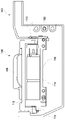
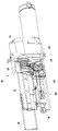
- FIG. 4 shows a moving mechanism 30 that moves the movable part 3 relative to the base 2.
- FIG. 4A shows the state of the moving mechanism 30 when the movable portion 3 is at the reference position
- FIG. 4B shows the state of the moving mechanism 30 when the movable portion 3 is retracted from the reference position. show.
- the moving mechanism 30 includes a rotary actuator 10, a feed screw 12, a nut 14, a guide mechanism 16, a rod 18, a fixed portion 20 and a rotation angle sensor 22, and slides the movable portion 3 in the longitudinal direction of the base 2.
- the rotary actuator 10 rotates the feed screw 12 forward or backward, thereby moving the nut 14 in the axial direction of the feed screw 12 (longitudinal direction of the base 2).
- a plurality of rods 18 are fixed to the nut 14 , and a fixed portion 20 fixed to the fixed portion of the movable portion 3 is attached to the distal end portion of the rod 18 .
- the rod 18 is guided in movement in the advancing direction by a guide mechanism 16 fixed to the inner wall of the base 2 .
- a rotation angle sensor 22 detects the rotation angle of the rotary actuator 10 , and the movement of the movable part 3 is controlled based on the detected value of the rotation angle sensor 22 .
- FIG. 5 shows an example of a switch mechanism 40 for user operation input.
- the haptic presentation device 1 of Example 1 includes a switch mechanism 40 that can be operated by a fingertip placed on the finger placement portion 5 .
- the switch mechanism 40 may be configured as a tactile switch having a contact structure 40b, and the user turns on the switch by pressing a push-type operation button 40a. It should be noted that the switch mechanism 40 may have other types of structures.
- the operation button 40a operated by the user is provided on the finger rest portion 5 on the rear side of the curved surface 4a.
- the operation button 40a may be used as an operation member for ejecting ink.
- the switch mechanism 40 has a spring member that biases the operation button 40a upward, and is configured so that the contact structure 40b is not turned on simply by placing the index finger on the operation button 40a. Since the tip of the index finger is not mainly involved in holding the force sense presentation device 1, the user can press the index finger placed on the finger rest 5 at any timing to operate the switch mechanism 40.
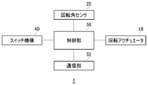
- FIG. 6 shows functional blocks of the force sense presentation device 1.
- the control unit 50 controls operations of the force sense presentation device 1 .
- the communication unit 52 transmits and receives data between the processing device that executes the drawing application and the haptic device 1 .
- the drawing application provides the haptic device 1 with reaction force data for generating reaction force due to the contact.
- the positional coordinates of the haptic device 1 in real space may be tracked using an external camera, or self-position may be estimated using a built-in IMU (Inertial Measurement Unit) or camera.
- IMU Inertial Measurement Unit
- the control unit 50 controls the rotary actuator 10 while monitoring the detection value of the rotation angle sensor 22 to move the movable unit 3 at the reference position in the direction to pull it into the base 2.
- the communication unit 52 transmits data indicating switch-on to the processing device. This allows the user to draw pictures and characters on the whiteboard using the virtual pen.
- the haptic presentation device 1 of the first embodiment in this manner, the user can enjoy drawing applications while feeling the force applied to the pen tip.
- FIG. 7 shows an example of the pushing member 6 provided on the movable part 3.
- the pushing member 6 is a member for presenting a force sensation to the palm of the hand, and is formed on the lower surface of the movable portion 3 .
- the pushing member 6 may be configured as a rod-shaped member that is pushed into the user's palm when the movable part 3 moves.
- FIG. 7(a) shows the movable part 3 at the reference position
- FIG. 7(b) shows the movable part 3 when moved in the direction in which it is pulled into the base 2. As shown in FIG.
- FIG. 8 shows a state in which the user holds the force sense presentation device 1.
- the movable part 3 is at the reference position and protrudes farthest forward from the base body 2 .
- the moving mechanism 30 moves the movable part 3 in the retracting direction from this state, the end of the pushing member 6 presses against the user's palm.
- the force sense presentation device 1 presents a force sense using not only the finger engaging portion 4 but also the pressing member 6, so that the user can feel more reaction force from the virtual object.
- the movement mechanism 30 moves the movable part 3 in the longitudinal direction of the base 2 to present the reaction force when the tip of the virtual pen contacts the virtual object (whiteboard) in the virtual space.
- the movement mechanism has a function of rotating the movable part around an axis parallel to the longitudinal direction of the base in order to present frictional force when the pen tip of the virtual pen moves on the virtual object.
- FIG. 9 shows a state in which the user holds the haptic presentation device 100 of the second embodiment.
- the force sense presentation device 100 includes a base 102 that is held by a user's hand, and a movable part 103 that is relatively movable with respect to the base 102 .
- the haptic presentation device 100 is a pen-shaped haptic device, and the substrate 102 has two side surfaces arranged substantially parallel to each other.
- the user uses the force sense presentation device 100 with both sides of the base 102 held between the thumb and middle finger and the index finger placed on the movable portion 103 .
- the movable part 103 in Example 2 can move relative to the base 102 in the longitudinal direction of the base 102 and can rotate relative to the axis parallel to the longitudinal direction of the base 102 .
- a switch installation member 106 having a switch mechanism 107 is provided on the side surface of the base 102, and the user touches the surface of the switch installation member 106 with the middle finger.
- the switch mechanism 107 has push-type operation buttons and may have the same structure as the switch mechanism 40 of the first embodiment. The user can turn on the switch by pressing the operation button with the middle finger.
- the haptic presentation device 100 of the second embodiment serves as a virtual pen that ejects ink in a drawing application for drawing pictures and letters on a whiteboard installed in a virtual space.
- a virtual pen that ejects ink in a drawing application for drawing pictures and letters on a whiteboard installed in a virtual space.
- the sliding movement of the movable part 103 with respect to the base 102 presents a force sensation in the pushing direction of the pen tip to the index finger
- the rotational movement of the movable part 103 with respect to the base 102 causes A force sense (corresponding to frictional force applied to the pen tip) is presented to the index finger in the direction opposite to the direction in which the pen tip moves on the whiteboard.
- FIG. 10 is a perspective view of the force sense presentation device 100.
- the side on which the movable portion 103 is provided is defined as the distal end side.
- the movable portion 103 is at the position where it protrudes most forward from the base 102, and this position is the "reference position" of the movable portion 103.
- the rotation angle of the movable portion 103 is zero, and this posture is the “reference posture” of the movable portion 103 .
- a finger rest part 105 is provided on the top surface of the movable part 103 for the user to place the tip of the index finger while gripping the base 102 .
- Finger engaging portions 104 with which the tips of the fingers are engaged are provided on both side portions and the front end portion of the finger rest portion 105 .
- the finger engaging portion 104 is formed in different directions from the two moving directions of the movable portion 103, that is, the longitudinal direction of the base 102 and the rotating direction about the axis parallel to the longitudinal direction. Specifically, the finger engaging portion 104 is erected on the upper surface of a beam member of a support base frame 112, which will be described later.
- the finger engaging portion 104 has a curved surface 104a that is slanted along the pad of the finger and has a curvature. Since the curved surface 104a is inclined with respect to the upper surface of the beam member and concave in the direction in which the fingertip is brought into contact, the user can stably bring the tip of the index finger into contact with the curved surface 104a.
- the user holds both sides of the base 102 with the thumb and middle finger as if holding a pen, places the pad of the index finger on the finger rest portion 105, and places the pad of the middle finger on the surface of the switch mounting member 106.
- the user may hold the substrate 102 with three or more fingers and place the pad of another finger, which is not mainly involved in holding the substrate 102 , on the finger rest portion 105 .
- the base 102 of the force sense presentation device 100 is held by two or more fingers, so that the base 102 can be fixed to the hand without requiring a special grasping mechanism for fixing the base 102 to the hand. can.
- FIG. 11 shows a moving mechanism 120 that rotates the movable portion 103 relative to the base 102 .
- the moving mechanism 120 includes a rotary actuator 110, a support frame 112, a base 114, a stopper 116, and a rotation angle sensor 118, and rotates the movable portion 103 about its axis.
- the fixed portion 20 shown in FIG. 4 is fixed to the fixed portion 122 of the movable portion 103 so that the movable portion 103 can be slidably moved by the moving mechanism 30 .
- the base portion 114 is fixed to the housing of the movable portion 103 and rotatably supports the support base frame 112 on which the finger rest portion 105 is installed.
- the support base frame 112 has a portal structure including a pair of pillar members and a beam member connecting the pair of pillar members.
- a finger rest part 105 is mounted on the upper surface.
- the rotary actuator 110 is fixed to the base 114 and the motor shaft is connected to one post of the support frame 112 . In the movement mechanism 120, the rotation actuator 110 rotates forward or backward, so that the support base frame 112 rotates rightward or leftward when the haptic device 100 is viewed from the front.
- a pair of stoppers 116 are formed on the base portion 114 , and the stoppers 116 restrict the rotation of the support base frame 112 .
- a rotation angle sensor 118 detects the rotation angle of the rotary actuator 110 , and the rotation of the movable part 103 is controlled based on the detection value of the rotation angle sensor 118 .
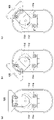
- FIG. 12 shows the inclination of the support base frame 112 when the haptic device 100 is viewed from the front.
- FIG. 12(a) shows the base 114 and the support frame 112 in the reference posture. In the reference posture, the rotation angle is 0 degree.
- FIG. 12(b) shows a state in which the support base frame 112 is rotated counterclockwise with respect to the base 114.
- FIG. The support base frame 112 is restricted from rotating by a stopper 116, and the maximum rotation angle when rotating to the left may be -45 degrees.
- FIG. 12(c) shows a state in which the support base frame 112 is rotated to the right with respect to the base 114.
- the rotation of the support base frame 112 is limited by a stopper 116, and the maximum rotation angle during clockwise rotation may be +45 degrees.
- FIG. 13 shows functional blocks of the force sense presentation device 100.
- the control unit 50 controls operations of the force sense presentation device 100 .
- the communication unit 52 transmits and receives data between the processing device that executes the drawing application and the haptic device 100 .
- the drawing application receives the reaction force data for generating the reaction force due to the pen movement.
- the control section 50 controls the rotary actuator 10 while monitoring the detection value of the rotation angle sensor 22 to move the movable section 103 at the reference position in the direction to pull it into the base 102.
- the index finger of the user receives a pressing force and/or a rotating force from the finger engaging portion 4, and the user feels that the pen is being moved on the whiteboard.
- the communication unit 52 transmits data indicating that the switch is turned on to the processing device. This allows the user to draw pictures and characters on the whiteboard using the virtual pen. By using the haptic presentation device 100 of the second embodiment in this manner, the user can enjoy drawing applications while feeling the force applied to the pen tip.
- the vibrator may be provided on the substrate 2, 102 held by the user. This enables the force sense presentation devices 1 and 100 to present the user with a tactile sense stimulus due to vibration. When presenting the haptic sensation, the haptic presentation devices 1 and 100 may output a sound representing the contact sound from the built-in speaker.
- the moving mechanism 30 uses the feed screw 12 to move the movable part 3 in the front-rear direction. You can move to
- FIG. 14 and 15 show a modification of the moving mechanism 30.
- FIG. The moving mechanism 30 has a reel 60 , a first pulley 62 , a second pulley 64 , a third pulley 66 , a fixed member 70 and a linear slider 72 .
- FIG. 16 shows a wire direct-acting mechanism extracted from the moving mechanism 30.
- a wire 68 is wound around a reel 60 , a first pulley 62 , a second pulley 64 and a third pulley 66 that constitute a wire linear motion mechanism, and the wire 68 moves as the reel 60 rotates.
- the user can adjust the wire tension so that the wire 68 is not loosened by operating the tension adjusting screw 74 to move the position of the third pulley 66 .
- a fixed portion (not shown) fixed to the fixed portion of the movable portion 3 is provided at the tip portion of the fixed member 70 .
- the fixed member 70 is fixed to the wire 68, and the linear slider 72 regulates the moving direction of the fixed member 70 in the front-rear direction.
- the rotation actuator 10 rotates the reel 60 forward or backward to move the wire 68 in the front-rear direction, thereby moving the movable part 3 fixed to the fixing member 70 in the front-rear direction.
- the present invention can be used for a device that is gripped by a user's hand and presents a force sensation to the user.
Landscapes
- Engineering & Computer Science (AREA)
- General Engineering & Computer Science (AREA)
- Theoretical Computer Science (AREA)
- Human Computer Interaction (AREA)
- Physics & Mathematics (AREA)
- General Physics & Mathematics (AREA)
- Position Input By Displaying (AREA)
Abstract
Priority Applications (1)
| Application Number | Priority Date | Filing Date | Title |
|---|---|---|---|
| JP2023503344A JPWO2022185560A1 (fr) | 2021-03-02 | 2021-07-02 |
Applications Claiming Priority (2)
| Application Number | Priority Date | Filing Date | Title |
|---|---|---|---|
| JP2021-032661 | 2021-03-02 | ||
| JP2021032661 | 2021-03-02 |
Publications (1)
| Publication Number | Publication Date |
|---|---|
| WO2022185560A1 true WO2022185560A1 (fr) | 2022-09-09 |
Family
ID=83155275
Family Applications (1)
| Application Number | Title | Priority Date | Filing Date |
|---|---|---|---|
| PCT/JP2021/025125 WO2022185560A1 (fr) | 2021-03-02 | 2021-07-02 | Dispositif de présentation à détection de force |
Country Status (2)
| Country | Link |
|---|---|
| JP (1) | JPWO2022185560A1 (fr) |
| WO (1) | WO2022185560A1 (fr) |
Citations (3)
| Publication number | Priority date | Publication date | Assignee | Title |
|---|---|---|---|---|
| JP2000200140A (ja) * | 1999-01-06 | 2000-07-18 | Nippon Telegr & Teleph Corp <Ntt> | 力覚提示方法及び力覚ペンタブレット |
| JP2010182315A (ja) * | 2000-05-24 | 2010-08-19 | Immersion Corp | 電気活性ポリマーを利用する触覚装置 |
| JP2016186696A (ja) * | 2015-03-27 | 2016-10-27 | ユニバーシティ・オブ・タンペレUniversity of Tampere | ハプティック・スタイラス |
-
2021
- 2021-07-02 JP JP2023503344A patent/JPWO2022185560A1/ja active Pending
- 2021-07-02 WO PCT/JP2021/025125 patent/WO2022185560A1/fr active Application Filing
Patent Citations (3)
| Publication number | Priority date | Publication date | Assignee | Title |
|---|---|---|---|---|
| JP2000200140A (ja) * | 1999-01-06 | 2000-07-18 | Nippon Telegr & Teleph Corp <Ntt> | 力覚提示方法及び力覚ペンタブレット |
| JP2010182315A (ja) * | 2000-05-24 | 2010-08-19 | Immersion Corp | 電気活性ポリマーを利用する触覚装置 |
| JP2016186696A (ja) * | 2015-03-27 | 2016-10-27 | ユニバーシティ・オブ・タンペレUniversity of Tampere | ハプティック・スタイラス |
Also Published As
| Publication number | Publication date |
|---|---|
| JPWO2022185560A1 (fr) | 2022-09-09 |
Similar Documents
| Publication | Publication Date | Title |
|---|---|---|
| JP4391193B2 (ja) | 操作装置 | |
| US6727889B2 (en) | Computer mouse input device with multi-axis palm control | |
| US20030160765A1 (en) | Facile ergonomic computer pointing device | |
| JP4671469B2 (ja) | ユーザの手で移動可能なコンピュータマウス | |
| WO2017130562A1 (fr) | Dispositif de rétroaction de sensation de force de préhension et dispositif de rétroaction de sensation de force de type stylet | |
| US9623566B2 (en) | Master apparatus for master slave apparatus, method for controlling the master apparatus, and the master slave apparatus | |
| JP2007504559A (ja) | コンピュータ及びビデオゲーム用のハンドマニピュレート情報機器 | |
| US5940066A (en) | Finger-mounted computer interface device | |
| WO2017009707A1 (fr) | Appareil et procédé pour type d'entrée hybride de boutons/touches et "écriture au doigt", et contrôleur manuel à profil bas/géométrie variable | |
| JP6296236B2 (ja) | マスタースレーブ装置用マスター装置及びその制御方法、及び、マスタースレーブ装置 | |
| WO2022185560A1 (fr) | Dispositif de présentation à détection de force | |
| JP2005524897A (ja) | 人間工学的形状のコンピュータポインティング装置 | |
| US20060007138A1 (en) | Pointing stick with function pad for two handed operation | |
| US20240134455A1 (en) | Force sense presentation device | |
| JP4695416B2 (ja) | 電子計算機用入力装置 | |
| JP2012150693A (ja) | 指示具および情報処理装置 | |
| KR19990037802A (ko) | 컴퓨터용마우스장치 | |
| CN112055605B (zh) | 用于计算设备的反馈控制器 | |
| JP4975371B2 (ja) | ビデオゲーム機やパソコン等の電子機器で使用されるコントローラ | |
| JP2002149334A (ja) | ポインティングデバイス装置 | |
| JPWO2022185560A5 (fr) | ||
| WO2018175054A1 (fr) | Mécanisme de déclenchement de segments de doigts multiples à un seul doigt | |
| JP2022169841A (ja) | 入力装置 | |
| JPH0962440A (ja) | ペン型ジョイスティック | |
| JPH06259186A (ja) | ポインティングデバイス |
Legal Events
| Date | Code | Title | Description |
|---|---|---|---|
| 121 | Ep: the epo has been informed by wipo that ep was designated in this application |
Ref document number: 21929130 Country of ref document: EP Kind code of ref document: A1 |
|
| WWE | Wipo information: entry into national phase |
Ref document number: 18264078 Country of ref document: US |
|
| WWE | Wipo information: entry into national phase |
Ref document number: 2023503344 Country of ref document: JP |
|
| NENP | Non-entry into the national phase |
Ref country code: DE |
|
| 122 | Ep: pct application non-entry in european phase |
Ref document number: 21929130 Country of ref document: EP Kind code of ref document: A1 |