WO2022185411A1 - 空気調和システム - Google Patents
空気調和システム Download PDFInfo
- Publication number
- WO2022185411A1 WO2022185411A1 PCT/JP2021/007955 JP2021007955W WO2022185411A1 WO 2022185411 A1 WO2022185411 A1 WO 2022185411A1 JP 2021007955 W JP2021007955 W JP 2021007955W WO 2022185411 A1 WO2022185411 A1 WO 2022185411A1
- Authority
- WO
- WIPO (PCT)
- Prior art keywords
- data
- air conditioning
- cop
- air
- air conditioner
- Prior art date
- Legal status (The legal status is an assumption and is not a legal conclusion. Google has not performed a legal analysis and makes no representation as to the accuracy of the status listed.)
- Ceased
Links
Images














Classifications
-
- F—MECHANICAL ENGINEERING; LIGHTING; HEATING; WEAPONS; BLASTING
- F24—HEATING; RANGES; VENTILATING
- F24F—AIR-CONDITIONING; AIR-HUMIDIFICATION; VENTILATION; USE OF AIR CURRENTS FOR SCREENING
- F24F11/00—Control or safety arrangements
- F24F11/30—Control or safety arrangements for purposes related to the operation of the system, e.g. for safety or monitoring
- F24F11/46—Improving electric energy efficiency or saving
-
- F—MECHANICAL ENGINEERING; LIGHTING; HEATING; WEAPONS; BLASTING
- F24—HEATING; RANGES; VENTILATING
- F24F—AIR-CONDITIONING; AIR-HUMIDIFICATION; VENTILATION; USE OF AIR CURRENTS FOR SCREENING
- F24F11/00—Control or safety arrangements
- F24F11/62—Control or safety arrangements characterised by the type of control or by internal processing, e.g. using fuzzy logic, adaptive control or estimation of values
- F24F11/63—Electronic processing
- F24F11/64—Electronic processing using pre-stored data
-
- F—MECHANICAL ENGINEERING; LIGHTING; HEATING; WEAPONS; BLASTING
- F24—HEATING; RANGES; VENTILATING
- F24F—AIR-CONDITIONING; AIR-HUMIDIFICATION; VENTILATION; USE OF AIR CURRENTS FOR SCREENING
- F24F11/00—Control or safety arrangements
- F24F11/70—Control systems characterised by their outputs; Constructional details thereof
- F24F11/80—Control systems characterised by their outputs; Constructional details thereof for controlling the temperature of the supplied air
- F24F11/86—Control systems characterised by their outputs; Constructional details thereof for controlling the temperature of the supplied air by controlling compressors within refrigeration or heat pump circuits
Definitions
- the present disclosure relates to an air conditioning system that controls the operation of an air conditioner.
- Air conditioners are desired to operate with efficient use of energy.
- the energy consumption efficiency of an air conditioner is also called a coefficient of performance (COP).
- the air conditioning control system described in Patent Document 1 includes a control device, air conditioning equipment, a detection device that detects environmental information and user information, and a cloud server.
- the cloud server calculates control parameters by performing data analysis based on history data such as room temperature, environmental information such as room temperature, and information such as user's body temperature.
- the control device generates a control command based on the control parameters from the cloud server, and controls the air conditioner according to the control command.
- Patent Document 1 a specific algorithm for data analysis is not specified, and it is difficult to operate the air conditioner in an appropriate operating state. Therefore, there is a problem that it is difficult to improve COP, which is energy consumption efficiency.
- the present disclosure has been made in view of the above, and aims to obtain an air conditioning system that can easily improve energy consumption efficiency.
- the air conditioning system of the present disclosure has multiple air conditioners and a cloud server that executes communication between the multiple air conditioners.
- the cloud server includes a receiving unit that receives data affecting the energy consumption efficiency of each air conditioner as air conditioning data from a plurality of air conditioners, and a storage unit that stores the air conditioning data. Further, when the cloud server receives the air conditioning data of a managed device, which is an air conditioner to be managed among the plurality of air conditioners, as managed data, the cloud server includes, in the air conditioning data, energy consumption efficiency of the managed data.
- the maximum air-conditioning data which is the air-conditioning data with the highest energy consumption efficiency, is selected from among the air-conditioning data.
- the apparatus includes an extraction unit that extracts data as appropriate driving data, and a transmission unit that transmits the appropriate driving data to the managed device. The managed device is driven using the appropriate driving data.
- the air conditioning system according to the present disclosure has the effect of easily improving energy consumption efficiency.
- FIG. 1 is a diagram showing the configuration of an air conditioning system according to an embodiment; FIG. The figure which shows the structure of the air conditioning apparatus with which the air conditioning system concerning embodiment is provided.
- FIG. 2 is a diagram showing an exterior configuration of an indoor unit included in the air conditioning system according to the embodiment; The figure which shows the structure of the cloud server with which the air conditioning system concerning embodiment is provided.
- FIG. 4 is a diagram showing COP information created by the cloud server according to the embodiment;
- FIG. 4 is a diagram showing COP information divided into a plurality of areas by the cloud server according to the embodiment based on the magnitude of the heat load factor;
- FIG. 4 is a diagram for explaining COP information when the cloud server according to the embodiment can search for a COP higher than the COP of the air conditioner to be managed;
- FIG. 5 is a diagram for explaining COP information when the cloud server according to the embodiment cannot search for a COP higher than the COP of the air conditioner to be managed;
- FIG. 4 is a diagram showing access determination information used by the interface terminal according to the embodiment when determining whether access to the cloud server is necessary;
- 4 is a flowchart showing a processing procedure of a process in which the cloud server according to the embodiment improves the COP by itself by changing each actuator;
- FIG. 4 is a diagram showing frequency rate, rotational speed rate, and opening rate for each temperature difference, which are used by the cloud server according to the embodiment;
- a diagram showing COP variation information in one of the areas shown in FIG. A diagram for explaining points in the COP information shown in FIG.
- FIG. 4 is a diagram for explaining points in COP information after the air conditioner according to the embodiment maintains the operation state of pattern PT1 for t hours;
- FIG. 17 shows COP change amount information in which the COP change amount of pattern PT1 after t time is registered with respect to the COP change amount information of FIG.
- FIG. 4 is a diagram for explaining unmeasured pattern search processing by the cloud server according to the embodiment;
- FIG. 4 is a diagram for explaining points in COP information after the air conditioner according to the embodiment maintains the operating state of pattern PT2 for t hours;
- FIG. 18 shows COP change amount information in which the COP change amount of pattern PT2 after t time is registered with respect to the COP change amount information of FIG.
- a diagram for explaining point P3 in area C10 A diagram showing COP variation information in an area containing the points shown in FIG. FIG.
- FIG. 4 is a diagram for explaining points in COP information after the air conditioner according to the embodiment maintains the operating state of pattern PT3 for t hours;
- FIG. 23 is a diagram showing COP change amount information in which the COP change amount after t time of pattern PT3 is registered with respect to the COP change amount information of FIG.
- FIG. 4 is a diagram for explaining points in COP information after the air conditioner according to the embodiment maintains the operating state for t hours in pattern PT4 in which the amount of change in COP after t hours has increased the most;
- FIG. 27 shows COP change amount information in which the COP change amount after t time of pattern PT4 is registered with respect to the COP change amount information of FIG.
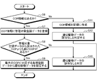
- FIG. 4 is a flow chart showing a procedure of feedback control by the air conditioning system according to the embodiment; 4 is a flow chart showing a procedure for extracting appropriate driving data by the cloud server according to the embodiment; FIG.
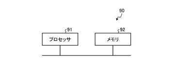
- FIG. 4 is a diagram showing a configuration example of a processing circuit provided in the cloud server according to the embodiment when the processing circuit is realized by a processor and a memory;
- FIG. 4 is a diagram showing an example of a processing circuit in the case where the processing circuit included in the cloud server according to the embodiment is configured with dedicated hardware;
- Embodiment. 1 is a diagram illustrating a configuration of an air conditioning system according to an embodiment; FIG.
- the air conditioning system 100 includes a cloud server 50 and multiple air conditioners. Although one air conditioner is illustrated in FIG. 1, the air conditioning system 100 includes a plurality of air conditioners.
- FIG. 1 shows a case where one air conditioner includes an air conditioner (air conditioner 70 described later), a remote controller (hereinafter referred to as a remote controller) 40, an interface terminal 60, and a cloud server 50.
- Air conditioner 70 includes indoor units 20A and 20B and outdoor unit 30 .
- the indoor units 20A and 20B are arranged indoors, and the outdoor unit 30 is arranged outdoors.
- the cloud server 50 which is an air conditioning management device, is a server that collects and accumulates data related to air conditioning of each air conditioning device 70 (various air conditioning data to be described later) from multiple air conditioning equipment.
- Each air conditioner from which the cloud server 50 collects various air conditioning data has the same function as the air conditioner in which the air conditioner 70 is arranged. That is, each air conditioner from which the cloud server 50 collects various air conditioning data includes an air conditioner 70 , a remote control 40 , and an interface terminal 60 .
- the cloud server 50 extracts appropriate drive data, which is drive data for operating each air conditioner 70 in an appropriate operating state, from various air conditioning data collected from a plurality of air conditioners, and transmits the data to each air conditioner. .
- the cloud server 50 extracts appropriate drive data for operating the air conditioner 70 in an appropriate operating state from various air conditioning data collected from a plurality of air conditioners, and transmits the data to the air conditioner 70. A case of doing so will be explained.
- Appropriate driving data is data that can improve COP, which is energy consumption efficiency.
- the air conditioner 70 absorbs indoor heat with the indoor units 20A and 20B, sends cool air into the room, and releases the absorbed heat from the outdoor unit 30 to lower the indoor temperature.
- the air conditioner 70 absorbs outside heat with the outdoor unit 30 and emits heat with the indoor units 20A and 20B to increase the indoor temperature.
- the air conditioner 70 uses thermistors in the indoor units 20A and 20B and the outdoor unit 30 to control the indoor temperature.
- the number of indoor units included in one air conditioner may be one, or may be three or more.
- the number of outdoor units 30, remote controllers 40, and interface terminals 60 included in one air conditioner may be two or more.
- the interface terminal 60 can communicate with the cloud server 50 and the remote control 40. Communication is performed between the interface terminal 60 and the cloud server 50 via a network. Communication is performed between the interface terminal 60 and the remote controller 40 by wireless connection.
- Wireless communication using Wi-Fi (registered trademark) or Bluetooth (registered trademark) is performed within the air conditioning equipment. Wireless communication is performed in the air conditioning equipment between the interface terminal 60 and the remote controller 40 and between the remote controller 40 and the indoor units 20A and 20B.
- the remote controller 40 can communicate with an indoor operation control device 200, which will be described later, provided in the indoor units 20A and 20B.
- the indoor operation control device 200 can communicate with an outdoor operation control device 300 which is provided in the outdoor unit 30 and will be described later.
- the remote controller 40 is a device for remotely operating the air conditioner 70 .
- Remote controller 40 receives an operation from a user and sends a command corresponding to the operation from the user to air conditioner 70 . Further, the remote controller 40 receives appropriate drive data from the interface terminal 60 and sends an operation command corresponding to the appropriate drive data to the indoor units 20A and 20B of the air conditioning device 70 .
- the interface terminal 60 has an application that serves as an interface between the cloud server 50 and the remote control 40.
- the interface terminal 60 is, for example, a smart phone or a tablet terminal.
- the indoor unit 20A Since the indoor units 20A and 20B are similar devices, the indoor unit 20A will be explained below when the indoor units 20A and 20B are explained.
- FIG. 2 is a diagram showing the configuration of an air conditioner included in the air conditioning system according to the embodiment.
- the air conditioner 70 of the air conditioning system 100 includes one indoor unit 20A will be described.
- the air conditioner 70 includes an indoor unit 20A and an outdoor unit 30.
- FIG. 2 shows the configuration of a refrigeration cycle extending over the indoor unit 20A and the outdoor unit 30 in the air conditioner 70. As shown in FIG.
- the indoor unit 20 ⁇ /b>A and the outdoor unit 30 are connected by a pipe 7 .
- the outdoor unit 30 includes a compressor 1, a four-way valve 2, a fan 3A, an outdoor heat exchanger 4, an outdoor two-phase tube temperature sensor 10, an outdoor liquid tube temperature sensor 11, a radiator plate 8, and a heat radiation sensor. 9 , an expansion valve 5 , a pipe 7 and an outside air temperature sensor 19 .
- the outdoor unit 30 has an outdoor operation control device 300.
- the outdoor operation control device 300 includes a compressor 1, a four-way valve 2, a fan 3A, an outdoor heat exchanger 4, an outdoor two-phase tube temperature sensor 10, an outdoor liquid tube temperature sensor 11, a heat radiation sensor 9, an expansion valve 5, and an outside air temperature. It is connected to sensor 19 . 2, the outdoor operation controller 300, the compressor 1, the four-way valve 2, the fan 3A, the outdoor heat exchanger 4, the outdoor two-phase tube temperature sensor 10, the outdoor liquid tube temperature sensor 11, the heat radiation sensor 9, the expansion Illustration of the valve 5 and connection lines with the outside air temperature sensor 19 is omitted.
- the outdoor operation control device 300 controls the compressor 1, the four-way valve 2, the fan 3A, the outdoor heat exchanger 4, and the expansion valve 5.
- the outdoor operation control device 300 also acquires data detected by the outdoor two-phase tube temperature sensor 10 , the outdoor liquid tube temperature sensor 11 , the heat radiation sensor 9 and the outside air temperature sensor 19 .
- the indoor unit 20A includes an indoor heat exchanger 6, a fan 3B, an indoor two-phase tube temperature sensor 12, an indoor liquid tube temperature sensor 13, a motion thermosensor 201, an indoor set temperature storage unit 16, and an indoor suction It has a temperature sensor 17 and a pipe 7 . Also, the indoor unit 20A has an indoor operation control device 200 . In addition, the indoor unit 20A may include a wind speed sensor that detects the wind speed of the wind coming out of the fan 3B.
- the compressor 1 In the refrigerant circuit composed of the indoor unit 20A and the outdoor unit 30, the compressor 1, the four-way valve 2, the outdoor heat exchanger 4, the radiator plate 8, the expansion valve 5, and the indoor heat exchanger 6 are piped. 7 are sequentially connected.
- the indoor operation control device 200 is connected to the indoor heat exchanger 6, the indoor two-phase tube temperature sensor 12, the indoor liquid tube temperature sensor 13, the motion thermosensor 201, the indoor preset temperature storage unit 16, and the indoor suction temperature sensor 17. ing. 2, the indoor operation control device 200, the indoor heat exchanger 6, the indoor two-phase tube temperature sensor 12, the indoor liquid tube temperature sensor 13, the motion sensor 201, the indoor set temperature storage unit 16, and the indoor suction Illustration of a connection line with the temperature sensor 17 is omitted.
- the indoor operation control device 200 controls the indoor heat exchanger 6 and the indoor preset temperature storage unit 16 .
- the indoor operation control device 200 also acquires data detected by the indoor two-phase tube temperature sensor 12 , the indoor liquid tube temperature sensor 13 , the motion thermosensor 201 , and the indoor suction temperature sensor 17 .
- the compressor 1 has its operating frequency adjusted by inverter control by the indoor operation control device 200, and compresses the refrigerant flowing through the refrigerant circuit.
- the four-way valve 2 is provided on the discharge side of the compressor 1 and switches between cooling operation and heating operation by switching the circulation direction of the refrigerant.
- the four-way valve 2 is, for example, an electromagnetic valve.
- the fan 3A cools the outdoor heat exchanger 4 by blowing air into the outdoor unit 30.
- the air volume of the fan 3 ⁇ /b>A is adjusted by adjusting the rotational speed under the control of the outdoor operation control device 300 .
- the outdoor heat exchanger 4 is a device that exchanges heat energy between refrigerants.
- the outdoor heat exchanger 4 performs heat exchange of refrigerant as a condenser and an evaporator.
- the outdoor two-phase tube temperature sensor 10 is a sensor that detects the temperature of the two-phase tube of the outdoor heat exchanger 4 .
- the outdoor liquid pipe temperature sensor 11 is a sensor that detects the temperature of a liquid pipe through which the liquid refrigerant in the outdoor heat exchanger 4 passes.
- the temperature of the liquid pipe detected by the outdoor liquid pipe temperature sensor 11 corresponds to the temperature of the liquid refrigerant in the outdoor heat exchanger 4 .
- the outdoor two-phase tube temperature sensor 10 and the outdoor liquid tube temperature sensor 11 send the detected temperatures to the outdoor operation controller 300 .
- the radiator plate 8 radiates heat from the control board on which the outdoor operation control device 300 is arranged.
- the heat radiation sensor 9 is a sensor that detects the temperature of the heat radiation plate 8 .
- the heat radiation sensor 9 sends the detected temperature to the outdoor operation control device 300 .
- the expansion valve 5 is a valve that reduces the pressure of the refrigerant condensed in the outdoor heat exchanger 4 .
- the expansion valve 5 is, for example, an electromagnetic valve.
- the outside air temperature sensor 19 is a sensor that detects the outside air temperature at the position where the outdoor unit 30 is arranged.
- the outdoor temperature sensor 19 sends the detected outdoor temperature to the outdoor operation control device 300 .
- the indoor heat exchanger 6 performs heat exchange of refrigerant as a condenser and an evaporator.
- the indoor two-phase tube temperature sensor 12 is a sensor that detects the temperature of the indoor heat exchanger 6 .
- the indoor liquid pipe temperature sensor 13 is a sensor that detects the temperature of the liquid refrigerant.
- the indoor two-phase tube temperature sensor 12 and the indoor liquid tube temperature sensor 13 send the detected temperatures to the indoor operation controller 200 .
- the fan 3B cools the indoor heat exchanger 6 by blowing air into the indoor unit 20A.
- the indoor set temperature storage unit 16 stores the indoor set temperature set by the user on the remote controller 40 .
- the indoor temperature stored in the indoor preset temperature storage unit 16 is read by the indoor operation control device 200 .
- the indoor intake temperature sensor 17 is a sensor that detects the temperature that is drawn into the room near the intake port of the indoor unit 20A (hereinafter referred to as indoor intake temperature). The indoor intake temperature sensor 17 sends the detected temperature to the indoor operation controller 200 .
- the indoor temperature stored in the indoor set temperature storage unit 16 may be read by the outdoor operation control device 300.
- the outdoor operation control device 300 controls the outdoor unit 30 using the indoor temperature.
- the temperature detected by the indoor intake temperature sensor 17 may be sent to the outdoor operation control device 300 .
- the outdoor operation control device 300 controls the outdoor unit 30 using the indoor intake temperature.
- the human thermosensor 201 is a sensor that detects the presence or absence of people in the room to be air-conditioned. In addition, the human thermosensor 201 detects heat sources other than people in the room and heat coming in and out from the outside. The human thermosensor 201 sends the detection result to the indoor operation control device 200 .
- Heat dissipation sensor 9, outdoor two-phase tube temperature sensor 10, outdoor liquid tube temperature sensor 11, indoor two-phase tube temperature sensor 12, indoor liquid tube temperature sensor 13, outdoor air temperature sensor 19, indoor suction temperature sensor 17, and human thermosensor 201 detects temperature using, for example, a thermistor.
- FIG. 3 is a diagram showing the external configuration of an indoor unit included in the air conditioning system according to the embodiment. As shown in FIG. 3, the human thermosensor 201 is arranged outside the indoor unit 20A.
- FIG. 4 is a diagram showing the configuration of a cloud server included in the air conditioning system according to the embodiment.
- the cloud server 50 includes a receiver 51 , a transmitter 53 , a storage 55 and an extractor 56 .
- the receiving unit 51 receives the operating data and environmental data for each air conditioner 70 transmitted from the interface terminal 60 via the network as various air conditioning data.
- Various air conditioning data received by the receiving unit 51 are data acquired by the indoor operation control device 200 or the outdoor operation control device 300 and are sent to the cloud server 50 via the remote control 40 and the interface terminal 60 .
- the receiving unit 51 sends the received various air conditioning data to the storage unit 55 .
- the operating data is data of the air conditioner 70 in operation.
- Examples of operating data include the frequency of the compressor 1, the number of revolutions of the fans 3A and 3B, the degree of opening of the four-way valve 2, the degree of opening of the expansion valve 5, the room set temperature, the room intake temperature, the actuator drive data, and the air conditioner 70. , and so on.
- the room set temperature is the temperature set in the remote control 40 by the user.
- the actuator driving data is data used for driving the actuator.
- the actuators here are actuators provided in the air conditioner 70 such as the compressor 1, the fans 3A and 3B, the expansion valve 5, and the like.
- the capacity band of the air conditioner 70 indicates the capacity range of the outdoor unit 30 . Further, when the indoor unit 20A includes a wind speed sensor, the wind speed detected by the wind speed sensor may be included in the operation data.
- the environmental data is data of the environment in which the air conditioner 70 is arranged.
- the environmental data includes outdoor air temperature, indoor crowd density, and the like.
- the indoor crowd density is calculated based on the size of the room and the number of people measured by the human thermosensor 201 .
- the environmental data also includes a heat load level, which will be described later.
- the environment data may also include sensor detection data that is data detected by sensors other than the outside air temperature sensor 19 and the human thermosensor 201 .
- the storage unit 55 is a memory or the like that accumulates various air conditioning data for each air conditioner 70 received from the interface terminal 60 .
- the storage unit 55 has a memory area large enough to store the data received for each air conditioner 70 operating on the market, and can keep these data in a state that can be stored for a long period of time.
- the cloud server 50 is capable of simultaneous communication with a plurality of interface terminals 60, and can ensure real-time performance of various air conditioning data accumulated in the storage unit 55.
- the extraction unit 56 extracts appropriate drive data from various air conditioning data accumulated in the storage unit 55 .
- the appropriate driving data is driving data used for driving the air conditioner 70 .
- suitable driving data are the frequency of the compressor 1, the number of revolutions of the fans 3A and 3B, the opening degree of the four-way valve 2, the opening degree of the expansion valve 5, actuator driving data, and the like.
- the extraction unit 56 creates COP information, which will be described later, based on various air conditioning data, and stores various air conditioning data for each air conditioner 70 in the COP information.
- the extracting unit 56 determines the similarity of various air conditioning data based on the capacity range of the air conditioner 70, the outside air temperature, the heat load level, etc. included in the various air conditioning data, and extracts COP information for each similar air conditioning data. create. That is, the extraction unit 56 creates COP information by grouping air conditioning data for each air conditioning data having similar operational data and environmental data.
- the extraction unit 56 causes the storage unit 55 to store the COP information including various air conditioning data. Thereby, the storage unit 55 stores COP information including air conditioning data grouped by air conditioning data having similar operational data and environmental data.
- the COP which is energy consumption efficiency, is information representing the energy performance of the air conditioner 70 .
- COP is, for example, an index of how much cooling effect or heating effect can be obtained using 1 kW of power.
- the cooling COP is indicated by cooling capacity (kw)/power consumption during cooling (kw).
- Appropriate driving data is driving data more suitable for driving the air conditioner 70 than the driving data included in the driving data sent from the interface terminal 60 .
- the driving data suitable for driving the air conditioner 70 is the driving data that can improve COP, which is the energy consumption efficiency. The details of the extraction process of the appropriate drive data by the extraction unit 56 will be described later.
- the transmission unit 53 transmits the appropriate driving data extracted by the extraction unit 56 to the interface terminal 60 via the network.
- the COP information is correspondence information indicating the correspondence between the COP and the heat load factor of the air conditioner 70 .
- the heat load factor [%] is calculated by the indoor operation control device 200, the cloud server 50, or the interface terminal 60.
- the indoor operation control device 200 calculates the heat load factor [%] by the average power [W]/maximum power [W] x 100 of the air conditioner 70 in the specific period.
- the specific period here is expressed in hours/days/months/years. Since the maximum electric power fluctuates greatly depending on the weather or outside air temperature, the calculation unit for the specific period is days at the longest, and ideally hours.
- the COP may be calculated by any of the indoor operation control device 200, the remote controller 40, and the interface terminal 60. In the following description, the case where the remote control 40 calculates the COP will be described.
- FIG. 5 is a diagram showing COP information created by the cloud server according to the embodiment.
- the horizontal axis of FIG. 5 is the heat load factor, and the vertical axis is the COP.
- FIG. 5 shows a case where the COP information is information obtained by plotting the heat load factor and the position indicating the COP. may be
- the COP information shown in FIG. 5 simulates a two-dimensional data table showing the correspondence between the heat load factor and the COP.
- the plotted points 601 are arranged at positions according to the correspondence relationship between the heat load factor and the COP for each air conditioner 70 .
- a point cloud 600 is a set of points 601 of each air conditioner 70 .
- the various air conditioning data received by the receiving unit 51 include the operating state of each air conditioner 70, the capacity range of each air conditioner 70, the outside air temperature, and the heat load level.
- the extraction unit 56 creates COP information based on various air conditioning data.
- the extraction unit 56 creates COP information for each combination of the operating state of each air conditioner 70, the capacity band of each air conditioner 70, the outside air temperature in a specific range, and the heat load level.
- the capacity band of the air conditioner 70, the outside air temperature in a specific range, and the heat load level, which are included in various air conditioning data, may be in any numerical range.
- FIG. 5 shows COP information in which the capacity band of the air conditioner 70 is Y horsepower, the outside air temperature range is x1° C. to x2° C. (x1 ⁇ x2), and the heat load level is L.
- FIG. 5 shows COP information in which the capacity band of the air conditioner 70 is Y horsepower, the outside air temperature range is x1° C. to x2° C. (x1 ⁇ x2), and the heat load level is L.
- the operating state is information as to whether each air conditioner 70 is performing cooling operation or heating operation.
- the heat load level is calculated by the indoor operation control device 200 .
- the heat load level is data obtained by quantifying the heat load of each air conditioner 70 .
- the heat load level is calculated for the room in which the indoor unit 20A is arranged.
- the heat load level is calculated using the human thermosensor 201 installed in each air conditioner 70, and the heat source data other than the human density in the room and the air coming in and out of the room from the outside.
- a later-described calculator 25 of the indoor operation control device 200 calculates based on the situation and the Ua value of the object to be air-conditioned.
- the volume of the room where the indoor unit 20A is arranged is stored in the indoor operation control device 200 in advance.
- Calculation unit 25 calculates the density of people based on the volume of the room and the number of people detected by motion thermosensor 201 .
- the density of people may be calculated by the remote controller 40, the interface terminal 60, or the cloud server 50.
- FIG. In this case, the volume of the room and the number of people detected by the human thermosensor 201 are included in various air conditioning data.
- the Ua value is an index that indicates the insulation performance of buildings such as houses, and is the value obtained by dividing the heat that escapes from inside the building by the outer skin area of the building.
- the Ua value is also called skin average heat transmission coefficient. A smaller Ua value indicates better heat insulation performance.
- the heat load level may be calculated by the extraction unit 56 of the cloud server 50, or may be calculated by the determination unit 65 of the interface terminal 60, which will be described later.
- the inflow and outflow of air from the outside is calculated based on the indoor temperature and the indoor intake temperature. Any of the extraction unit 56 of the cloud server 50, the determination unit 65 of the interface terminal 60, and the calculation unit 25 of the indoor operation control device 200 may calculate the inflow/outflow of air from the outside.
- the extraction unit 56 searches for the COP information corresponding to the received various air conditioning data by comparing the operating data and environmental data included in the various air conditioning data received from the interface terminal 60 with the COP information. That is, the extraction unit 56 searches for COP information containing operating data and environmental data similar to the operating data and environmental data included in the various air conditioning data received from the interface terminal 60 .
- Various air conditioning data received by the cloud server 50 from the interface terminal 60 include various air conditioning data for the air conditioner 70 that is the object of management in this embodiment.
- Various types of air conditioning data of the air conditioner 70 which is a device to be managed, may be hereinafter referred to as air conditioning data to be managed.
- the extractor 56 registers the managed air-conditioning data in the identified COP information.
- the extraction unit 56 plots a point 601 at a position corresponding to the heat load factor and COP calculated from the managed air conditioning data.
- the extractor 56 plots a point 601 for each air conditioner 70 .
- the extraction unit 56 associates each point 601 with various air conditioning data. Accordingly, by specifying the point 601 , the extraction unit 56 can acquire various air conditioning data corresponding to the point 601 .
- the extraction unit 56 If the extraction unit 56 cannot uniquely identify the COP information corresponding to the managed air conditioning data, it newly creates the COP information corresponding to this managed air conditioning data.
- the extraction unit 56 newly creates COP information according to the temperature width of the outside air temperature zone.
- the extraction unit 56 extracts appropriate driving data from the specified COP information.
- the extraction unit 56 divides the specified COP information into a plurality of areas based on the magnitude of the heat load factor.
- the extraction unit 56 selects an area corresponding to the heat load factor of the air conditioner 70 to be managed from among the plurality of divided areas.
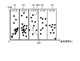
- FIG. 6 is a diagram showing COP information divided into a plurality of areas by the cloud server according to the embodiment based on the magnitude of the heat load factor.
- the horizontal axis of FIG. 6 is the heat load factor, and the vertical axis is the COP.
- the COP information shown in FIG. 6 is COP information obtained by dividing the COP information shown in FIG. 5 into a plurality of areas.
- the extraction unit 56 shows COP information when the COP information is divided into areas A1 to A5.
- Area A1 has a heat load factor in the first range
- area A2 has a heat load factor in the second range.
- Area A3 has a thermal load factor in the third range (third thermal load factor band)
- area A4 has a thermal load factor in a fourth range
- area A5 has a thermal load factor in the fifth range. Range.
- the heat load factor divided into specific ranges by areas A1 to A5 may be referred to as a heat load factor zone.
- Area A1 is the first heat load factor zone, and area A2 is the second heat load factor zone.
- Area A3 is the third heat load rate zone.
- Area A4 is the fourth heat load factor zone, and area A5 is the fifth heat load factor zone.
- an area with a heat load factor of 0 or more and less than B1 is area A1
- an area with a heat load factor of B1 or more and less than B2 (B2>B1) is area A2.
- Area A3 is an area where the heat load factor is B2 or more and less than B3 (B3>B2)
- area A4 is an area where the heat load factor is B3 or more and less than B4 (B4>B3).
- Area A5 is an area where the load factor is equal to or greater than B4 and less than B5 (B5>B4).
- the extraction unit 56 selects an area corresponding to the heat load factor of the air conditioner 70 to be managed from among the plurality of divided areas A1 to A5.
- the extraction unit 56 searches for a COP that is higher than the COP of the air conditioner 70 and that has the maximum COP in the selected area.
- the extraction unit 56 extracts appropriate drive data from various air conditioning data corresponding to the retrieved COP. That is, the extraction unit 56 extracts appropriate drive data from various air conditioning data stored in the storage unit 55 .
- the transmission unit 53 transmits the appropriate driving data extracted by the extraction unit 56 to the interface terminal 60 .
- the interface terminal 60 transmits appropriate drive data to the air conditioner 70 via the remote controller 40 . Thereby, the air conditioner 70 performs feedback control using the appropriate drive data.
- the interface terminal 60 repeats the process of transmitting various air conditioning data to the cloud server 50. Further, the cloud server 50 repeats the process of extracting appropriate driving data based on various air conditioning data and COP information. Also, the air conditioner 70 repeats the feedback control using the appropriate drive data. By continuing such feedback control, the air conditioning system 100 can quickly bring the air conditioning device 70 closer to the optimum operating state, and improve the COP of the air conditioning device 70.
- the extraction unit 56 determines that the various air conditioning data corresponding to the COP of the air conditioner 70 is appropriate drive data. do. In this case, the transmission unit 53 does not transmit the appropriate drive data to the interface terminal 60, and feedback control of the air conditioner 70 is not executed.
- the cloud server 50 also extracts and transmits appropriate drive data for air conditioners other than the air conditioner 70 in the same manner as the air conditioner 70 .
- the air conditioner that executes feedback control is the air conditioner to be managed.
- FIG. 7 is a diagram for explaining COP information when the cloud server according to the embodiment can search for a COP higher than the COP of the air conditioner to be managed.
- FIG. 7 shows a case where the extracting unit 56 has successfully searched for a COP that is higher than the COP of the air conditioner 70 and has the maximum COP for the COP information shown in FIG.
- FIG. 7 shows a case where the extraction unit 56 selects the area A3 as the area corresponding to the heat load of the air conditioner 70 from among the areas A1 to A5.
- a point 602 corresponds to the air conditioning data to be managed among the points in the area A3.
- some points in area A3 have a higher COP than the COP of point 602 .
- a point 603 indicates a point that is higher than the COP of the point 602 and that has the maximum COP in the area A3.
- the extraction unit 56 extracts a point 603 from within the area A3 and extracts appropriate drive data from various air conditioning data corresponding to the point 603 .
- FIG. 8 is a diagram for explaining COP information when the cloud server according to the embodiment cannot search for a COP higher than the COP of the air conditioner to be managed.
- FIG. 8 shows a case where the extraction unit 56 cannot retrieve a COP higher than the COP of the air conditioner 70 for the COP information shown in FIG.
- FIG. 8 shows a case where the extraction unit 56 selects the area A3 as the area corresponding to the heat load of the air conditioner 70 from the areas A1 to A5.
- a point 602 corresponds to the air conditioning data to be managed among the points in the area A3.
- no point in area A3 has a higher COP than the COP of point 602 .
- the extraction unit 56 does not extract the appropriate drive data from the storage unit 55 .
- the transmission unit 53 does not transmit the appropriate drive data to the interface terminal 60 .
- the cloud server 50 classifies various accumulated air conditioning data according to the installation environment of each air conditioner 70 . That is, the cloud server 50 creates COP information for each type of similar air conditioning data. As a result, the cloud server 50 can set the accumulated data under the similar environment as the target value of the feedback control of the air conditioner 70, that is, the appropriate drive data. As a result, the air conditioner 70 to be managed can utilize various air conditioning data of air conditioners in different installation environments. As a result, the air conditioning system 100 can easily improve the COP of the air conditioner 70 .
- a part of the processing executed by the cloud server 50 may be executed by the interface terminal 60.
- FIG. 9 is a diagram showing the configuration of an interface terminal included in the air conditioning system according to the embodiment.
- the interface terminal 60 includes receivers 61 and 62 , transmitters 63 and 64 , and a determiner 65 .
- the receiving unit 61 receives various air conditioning data from the remote controller 40 by executing communication with the remote controller 40 by wireless connection.
- the determination unit 65 analyzes various air conditioning data received from the remote controller 40 and determines whether access to the cloud server 50 is necessary based on the analysis results. The determining unit 65 determines that access to the cloud server 50 is necessary when at least one of the following (X1) to (X4) is satisfied.
- the determination unit 65 determines that access to the cloud server 50 is unnecessary when at least one of (X5) and (X6) below is satisfied.
- the transmission unit 63 transmits various air conditioning data to the cloud server 50 .
- the receiving unit 62 receives appropriate driving data from the cloud server 50 .
- the transmission unit 64 transmits appropriate drive data to the remote controller 40 by executing communication with the remote controller 40 by wireless connection.
- the heat load level will switch frequently when there are many people coming in and out of the room.
- new appropriate driving data which is the next target value, is set in the air conditioner 70 before the appropriate state is achieved by feedback control. It is assumed that the control does not converge. Therefore, the determination unit 65 may determine that access to the cloud server 50 is unnecessary when the heat load level fluctuates more than a specific value.
- the temperature threshold is a threshold used to determine whether or not to access the cloud server 50 .
- the temperature threshold is the temperature at the boundary between the current outside air temperature zone and another outside air temperature zone. In other words, the temperature thresholds are the maximum and minimum temperatures of the ambient temperature zone.
- the outside air temperature fluctuates throughout the day, but it is thought that the fluctuations within a specific time period are small. Therefore, the outside air temperature may fluctuate around the threshold.
- the appropriate drive data is always updated and the feedback control does not converge. Therefore, the determination unit 65 may determine that access to the cloud server 50 is unnecessary when the outside air temperature fluctuates up and down near the threshold. For example, when the outside air temperature fluctuates so as to cross over the temperature threshold a specific number of times within a specific period of time, the determination unit 65 determines that access to the cloud server 50 is unnecessary.
- the cloud server 50 can handle the other outside temperature zone. Appropriate drive data for feedback control is extracted using the COP information.
- the determination unit 65 sets 26° C. or 28° C. M times (M is 2 If the outside air temperature fluctuates over the above natural numbers), it is determined that access to the cloud server 50 is unnecessary.
- the determination unit 65 determines that the outside temperature is stable at a value lower than 26° C. or higher than 28° C. In this case, appropriate drive data for feedback control is extracted from the COP information corresponding to the stable state.
- the determination unit 65 may allow the outside air temperature range to make a determination. For example, when the feedback control is performed using the COP information corresponding to the outside temperature range of 26° C. to 28° C., if the outside temperature is within the range of 25° C. to 26° C., the determination unit 65 Continue to use the COP information corresponding to the ambient temperature range of °C to 28 °C. Similarly, if the outside air temperature is within the range of 28.degree. C. to 29.degree. In this way, the determination unit 65 can suppress frequent update of the target value by providing hysteresis in determination of the temperature threshold.
- the interface terminal 60 can suppress frequent updating of target values by limiting the timing of accessing the cloud server 50, that is, the timing of accumulating various air conditioning data. As a result, the interface terminal 60 can shorten the period until the operating state of the air conditioner 70 converges to an appropriate state.
- the interface terminal 60 can suppress communication congestion of the cloud server 50 by suppressing access to the cloud server 50 .
- the interface terminal 60 can suppress the data storage capacity of the cloud server 50 by suppressing access to the cloud server 50 .
- FIG. 10 is a diagram illustrating access determination information used by the interface terminal according to the embodiment when determining whether access to the cloud server is necessary; FIG.
- the determination unit 65 uses the access determination information 210 to determine whether access to the cloud server 50 is required.
- the access determination information 210 a combination of information from (Y1) to (Y5) below is associated with whether access to the cloud server 50 is necessary.
- “No care” in the access determination information 210 in FIG. 10 indicates that "Yes” or “No” is acceptable. Also, “required” in the access determination information 210 indicates that access to the cloud server 50 is required. “No” in the access determination information 210 indicates that access to the cloud server 50 is unnecessary.
- the determination unit 65 determines that access to the cloud server 50 is necessary when feedback control is not being executed and execution of feedback control is permitted. Moreover, the determination unit 65 determines that access to the cloud server 50 is unnecessary when execution of feedback control is not permitted.
- the determination unit 65 determines that access to the cloud server 50 is unnecessary until the appropriate value is reached. . Also, when the heat load factor changes from the current heat load zone to another heat load zone, the determination unit 65 determines that access to the cloud server 50 is necessary.
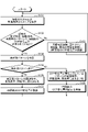
- FIG. 11 is a flowchart of a process procedure for improving the COP by the cloud server according to the embodiment by changing actuators.
- the extracting unit 56 calculates the difference between the set temperature set in the remote controller 40 and the indoor temperature acquired from the indoor unit 20A.
- a certain temperature difference is classified into three types: large, medium, and small.
- the extractor 56 also determines the frequency rate, rotation speed rate, and opening rate that can be operated within each class of temperature difference.
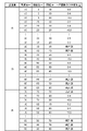
- FIG. 12 is a diagram showing the frequency rate, rotational speed rate, and opening rate for each temperature difference, which are used by the cloud server according to the embodiment.
- the compressor frequency is the frequency of the compressor 1 and the maximum compressor frequency is the maximum value of the compressor frequency.
- the outdoor fan rotation speed is the rotation speed of the fan 3A provided in the outdoor unit 30, and the maximum outdoor fan rotation speed is the maximum value of the outdoor fan rotation speed.
- the expansion valve opening degree is the opening degree of the expansion valve 5
- the maximum expansion valve opening degree is the maximum value of the expansion valve opening degree.
- the extraction unit 56 sets one or more ranges as the frequency rate, rotation speed rate, and opening rate for each classification of the temperature difference. For example, the extraction unit 56 selects three ranges of 10 to 19%, 20 to 29%, and 30 to 39% (for example, 10 % range). In addition, the extraction unit 56 sets three ranges of 40 to 49%, 50 to 59%, and 60 to 69% as the frequency rate, rotation speed rate, and opening rate for the temperature difference, for example. do. In addition, the extraction unit 56 sets three ranges of 70 to 79%, 80 to 89%, and 90 to 100% for the frequency rate, rotation speed rate, and opening rate, for example, with respect to the large temperature difference. do.
- the user may set the frequency rate, rotation speed rate, and opening rate that can be operated in each classification of the temperature difference.
- a plurality of expansion valves 5 are installed in the outdoor unit 30, a plurality of opening degrees may be set.
- the extraction unit 56 searches for the COP information corresponding to the received various air conditioning data by comparing the operating data and environmental data included in the various air conditioning data received from the interface terminal 60 with the COP information.
- the extraction unit 56 divides the specified COP information into a plurality of areas based on the magnitude of the heat load factor and the magnitude of the COP.
- the extraction unit 56 selects an area corresponding to the heat load factor and COP of the air conditioner 70 to be managed from among the plurality of divided areas.
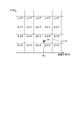
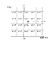
- FIG. 13 is a diagram showing COP information divided into a plurality of areas by the cloud server according to the embodiment based on the magnitude of the heat load factor and the magnitude of the COP.
- the horizontal axis of FIG. 13 is the heat load factor, and the vertical axis is the COP.
- the COP information shown in FIG. 13 the COP information is divided into a plurality of areas by equally spaced lines parallel to the vertical axis and equally spaced lines parallel to the horizontal axis.
- FIG. 13 shows a case where the extraction unit 56 divides the COP information into areas C1 to C20.
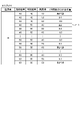
- the extraction unit 56 extracts COP change amount information indicating the correspondence relationship between the magnitude of the temperature difference, the frequency rate, the rotational speed rate, the opening rate, and the COP change amount after time t for each of the areas C1 to C20. It is stored in the storage unit 55 .
- FIG. 14 is a diagram showing COP variation information in one of the areas shown in FIG. FIG. 14 shows COP variation information in any of areas C1 to C20.
- the COP change amount information the magnitude of the temperature difference, the frequency rate, the rotational speed rate, the opening rate, and the COP change amount after time t are associated with each other.
- the amount of COP change after t hours is the difference between the COP before and after the air conditioner 70 has been operated for t hours.
- the COP change amount after operating the air conditioner 70 for t hours is -0.3. be.
- the time t can be freely set.
- a line unit such as "frequency rate of 10%, rotational speed rate of 20%, opening rate of 30%" will be referred to as a "pattern". That is, the pattern is a combination of frequency rate, rotation speed rate, and opening rate.
- the combination of the heat load factor and the COP in the COP information will be referred to as a "point". That is, the point is the combination of the heat load factor and the COP in the current air conditioner 70 .
- FIG. 15 is a diagram for explaining points in the COP information shown in FIG.
- the cloud server 50 disables feedback control using the COP information during startup control of the air conditioner 70 .
- the point of the air conditioner 70 after completion of start-up control is defined as point P1.
- the extraction unit 56 identifies an area containing the point P1 from the current COP and heat load factor of the point P1 (step S101).
- the extraction unit 56 here determines that the point P1 belongs to the area C14.
- the storage unit 55 holds COP variation information as shown in FIG. 16 as the data in area C14.
- FIG. 16 is a diagram showing COP variation information in an area containing the points shown in FIG.
- the COP change amount information for the part where the magnitude of the temperature difference is "medium” will be described as the COP change amount information.
- FIG. 16 shows the COP variation information for area C14.
- the extraction unit 56 determines whether or not the COP change amount after t time has been measured with the current pattern of the frequency rate, rotation speed rate, and opening rate (step S102).
- each actuator state at point P1 has a frequency rate of 40%, a rotation speed rate of 50%, and an opening rate of 40%.
- the COP change amount after time t is "unmeasured.”
- the extraction unit 56 determines that the COP change amount after time t is "unmeasured” in the pattern PT1 with a frequency rate of 40%, a rotation speed rate of 50%, and an opening rate of 40%. .
- the cloud server 50 maintains the current operating state of pattern PT1 for t time, and measures the COP change amount. That is, when the COP change amount has not been measured, the cloud server 50 maintains the compressor frequency, the outdoor fan rotation speed, and the expansion valve opening degree, and operates the air conditioner 70 for t hours.
- FIG. 17 is a diagram for explaining points in COP information after the air conditioner according to the embodiment maintains the operating state of pattern PT1 for t hours.
- a point P2 indicates a point after the operating state of the pattern PT1 is maintained for t time.
- the extraction unit 56 measures the amount of change in COP after time t when the operation is performed while maintaining the compressor frequency, the outdoor fan rotation speed, and the expansion valve opening degree, and registers it in the storage unit 55 (step S103).
- the extraction unit 56 here measures and stores the amount of change in COP after time t when operated while maintaining the frequency rate of 40%, the rotation speed rate of 50%, and the opening rate of 40%. register in section 55;
- the amount of change in COP after time t is the amount of change in COP from before operation to after operation.
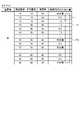
- FIG. 18 is a diagram showing COP change amount information in which the COP change amount of pattern PT1 after t time is registered with respect to the COP change amount information of FIG.
- FIG. 18 shows the COP variation information for area C14.
- the extraction unit 56 registers the measured COP change amount after t time for the pattern PT1 of the COP change amount information.
- the cloud server 50 returns to the process of step S101. That is, since it is expected that at least one of the COP and the heat load factor changes between the point P1 and the point P2, the extraction unit 56 identifies the latest area from the COP and the heat load factor of the point P2. (Step S101).
- the extraction unit 56 determines whether or not the COP change amount after t time has been measured in the current pattern PT1 of the area C14. That is, the extraction unit 56 determines whether or not the COP change amount after time t has been measured with the current pattern of the frequency rate, rotation speed rate, and opening rate (step S102).
- step S103 the cloud server 50 has already measured the COP change amount after t hours for the pattern PT1 in the area C14. If the amount of change in COP after time t has been measured in the current pattern (step S102, Yes), the extraction unit 56 searches for unmeasured patterns that are unmeasured patterns in other patterns in area C14. (Step S104).
- the extraction unit 56 searches for unmeasured patterns in order from the current pattern PT1 toward lower patterns. Note that the search algorithm for the unmeasured pattern by the extraction unit 56 is not particularly defined.
- FIG. 19 is a diagram for explaining unmeasured pattern search processing by the cloud server according to the embodiment.
- the extraction unit 56 searches for unmeasured patterns in the order of the arrow 71 . Specifically, the extracting unit 56 determines whether or not the pattern one level below the pattern PT1 is an unmeasured pattern, and if not, the pattern one level below is an unmeasured pattern. The process of determining whether or not there is is repeated. When the unmeasured pattern search processing is completed up to the bottom pattern, the extraction unit 56 determines whether or not the top pattern is the unmeasured pattern.
- the extraction unit 56 determines whether or not all patterns are unmeasured patterns, and extracts unmeasured patterns.
- FIG. 19 shows a case where the extraction unit 56 searches for the pattern PT2 as the unmeasured pattern.
- the extraction unit 56 determines whether or not each pattern is an unmeasured pattern, and determines whether or not there is an unmeasured pattern in the area C14 (step S105). If there is an unmeasured pattern in area C14 (step S105, Yes), the extraction unit 56 changes each actuator to the frequency rate, rotational speed rate, and opening rate of the unmeasured pattern (step S106).
- the extraction unit 56 here changes each actuator to 50%, which is the frequency rate of the pattern PT2, 50%, which is the rotational speed rate of the pattern PT2, and 40%, which is the opening rate of the pattern PT2. Further, the extractor 56 operates the air conditioner 70 for t hours in this state.
- FIG. 20 is a diagram for explaining points in COP information after the air conditioner according to the embodiment maintains the operating state of pattern PT2 for t hours.
- a point P3 indicates a point after the operating state of the pattern PT2 is maintained for t time.
- the extraction unit 56 measures the amount of change in COP after time t when operating while maintaining the compressor frequency, the outdoor fan rotation speed, and the expansion valve opening degree, and registers it in the storage unit 55 (step S107).
- the extraction unit 56 here measures and stores the amount of COP change after time t when the operation is performed while maintaining the frequency rate of 50%, the rotation speed rate of 50%, and the opening rate of 40%. register in section 55;
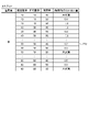
- FIG. 21 is a diagram showing COP change amount information in which the COP change amount of pattern PT2 after t time is registered with respect to the COP change amount information of FIG.
- FIG. 21 shows the COP variation information for area C14.
- the extraction unit 56 registers the measured COP change amount after t time for the pattern PT2 of the COP change amount information.
- the extraction unit 56 registers the COP change amount after t time with respect to the COP change amount information of the area C10.
- FIG. 22 is a diagram for explaining point P3 in area C10.
- a point P3 shown in FIG. 22 exists within the area C10.
- the point P3 in the area C10 is stored in the storage unit 55 in association with the COP variation information of the area C10.
- FIG. 23 is a diagram showing COP variation information in an area containing the points shown in FIG.
- the storage unit 55 stores the COP change amount information for the area C10 in the same manner as the COP change amount information for the area C14. That is, the storage unit 55 holds the pattern and the amount of COP change after t time for the pattern in the area C10 as well as in the area C14.
- the cloud server 50 After the latest COP change amount is registered in the COP change amount information, the cloud server 50 returns to the process of step S101. That is, the extraction unit 56 identifies the latest area from the COP and heat load factor of point P3 (step S101).
- the extraction unit 56 determines whether or not the COP change amount after time t has been measured in the current pattern PT3 of the area C10. That is, the extraction unit 56 determines whether or not the COP change amount after time t has been measured with the current pattern of the frequency rate, rotation speed rate, and opening rate (step S102).
- the extraction unit 56 here determines whether or not the COP change amount after time t has been measured for the operating state in which the frequency rate is 50%, the rotational speed rate is 50%, and the opening rate is 40%. judge.
- the extraction unit 56 searches for unmeasured patterns from other patterns in area C10 (step S104).
- the extraction unit 56 here searches for unmeasured patterns in the order of the arrow 72 .
- the search processing of the unmeasured pattern by the extraction unit 56 is the same as the processing described with reference to FIG. 19, so detailed description thereof will be omitted.
- FIG. 23 shows a case where the extraction unit 56 searches for the pattern PT3 as the unmeasured pattern.
- the extraction unit 56 determines whether or not each pattern is an unmeasured pattern, and determines whether or not there is an unmeasured pattern in the area C10 (step S105). If there is an unmeasured pattern in area C10 (step S105, Yes), the extraction unit 56 changes each actuator to the frequency rate, rotational speed rate, and opening rate of the unmeasured pattern (step S106). For example, the extraction unit 56 changes each actuator to 50%, which is the frequency rate of the pattern PT3, 50%, which is the rotational speed rate of the pattern PT3, and 60%, which is the opening rate of the pattern PT3. Further, the extractor 56 operates the air conditioner 70 for t hours in this state.
- FIG. 24 is a diagram for explaining points in COP information after the air conditioner according to the embodiment maintains the operating state of pattern PT3 for t hours.
- a point P4 indicates a point after the operating state of the pattern PT3 is maintained for t time.
- the extraction unit 56 measures the amount of change in COP after time t when operating while maintaining the compressor frequency, the outdoor fan rotation speed, and the expansion valve opening degree, and registers it in the storage unit 55 (step S107).
- the extraction unit 56 here measures and stores the amount of change in COP after time t when operated while maintaining the frequency rate of 50%, the rotational speed rate of 50%, and the opening rate of 60%. register in section 55;
- FIG. 25 is a diagram showing COP change amount information in which the COP change amount of pattern PT3 after t time is registered with respect to the COP change amount information of FIG.
- FIG. 25 shows the COP variation information for area C10.
- the extraction unit 56 registers the measured COP change amount after t time for the pattern PT3 of the COP change amount information.
- the extraction unit 56 registers the COP change amount after t time with respect to the COP change amount information of area C11.
- FIG. 26 is a diagram showing COP variation information in an area containing the points shown in FIG. FIG. 26 shows the COP variation information for area C11.
- the storage unit 55 stores the COP change amount information for the area C11 in the same manner as the COP change amount information for the area C10. That is, the storage unit 55 holds the pattern and the COP change amount after t time for the pattern in the area C11 as well as in the area C10.
- the cloud server 50 returns to the process of step S101. That is, the extraction unit 56 identifies the latest area from the COP and heat load factor of point P4 (step S101).
- the extraction unit 56 determines whether or not the COP change amount after time t has been measured in the current pattern PT3 of the area C10. That is, the extraction unit 56 determines whether or not the COP change amount after time t has been measured with the current pattern of the frequency rate, rotation speed rate, and opening rate (step S102).
- the extraction unit 56 here determines whether or not the COP change amount after time t has been measured for the operating state in which the frequency rate is 50%, the rotational speed rate is 50%, and the opening rate is 60%. judge.
- the extraction unit 56 searches for unmeasured patterns from other patterns in area C11 (step S104).
- the extraction unit 56 selects the pattern with the highest COP variation after t from all the patterns in the area C11. Then, the extraction unit 56 changes each actuator to the pattern with the largest COP increase amount after time t, that is, the pattern with the largest increase in the COP change amount (step S108). In the example shown in FIG. 26, the extraction unit 56 changes each actuator so that the frequency rate is 60%, the rotational speed rate is 60%, and the opening rate is 40%.
- FIG. 27 illustrates points in the COP information after the air conditioner according to the embodiment maintains the operating state for t hours in the pattern PT4 in which the amount of change in COP after t hours is the highest. It is a figure for doing.
- a point P5 indicates a point after the operating state of the pattern PT4 is maintained for t time. Point P5 has, for example, the same coordinates as point P4.
- the extraction unit 56 measures the amount of change in COP after time t when operated while maintaining the compressor frequency, outdoor fan rotation speed, and expansion valve opening degree, and registers it in the storage unit 55 (step S109).
- the extraction unit 56 calculates the amount of COP change (second time) after time t when operating while maintaining the frequency rate of 60%, the rotation speed rate of 60%, and the opening rate of 40%. It is measured and registered in the storage unit 55 .
- FIG. 28 is a diagram showing COP change amount information in which the COP change amount after t time for pattern PT4 is registered with respect to the COP change amount information in FIG.
- FIG. 28 shows the COP variation information for area C11.
- the extracting unit 56 registers the second COP change amount measured after t time for the pattern PT4 of the COP change amount information. In addition, the extraction unit 56 updates the average value of the COP change amount after t time.
- the cloud server 50 After the average value of the COP variation after t hours is updated, the cloud server 50 returns to the process of step S101 and repeats the processes of steps S101 to S109.
- the extraction unit 56 measures the Nth (N is a natural number equal to or greater than 2) COP change amount and registers it in the storage unit 55 in step S109.
- the extraction unit 56 updates the average value of the COP change amount after t time.
- the extraction unit 56 preferentially implements the pattern in which the amount of COP change increases the most among the average values of the amount of change in COP after t time. continue.
- FIG. 29 shows the points in the COP information after the air conditioner according to the embodiment maintains the operating state for t hours in a pattern in which the average value of the COP variation after t hours has increased the most. It is a figure for explaining.
- a point P6 indicates a point after the operating state is maintained for t hours in a pattern in which the average value of the COP change amount after t hours has increased the most.
- the pattern PT3 is the pattern in which the average value of the COP variation after t hours has increased the most. Therefore, the extraction unit 56 changes each actuator so that the pattern PT3 is obtained, that is, the frequency rate is 50%, the rotational speed rate is 50%, and the opening rate is 60%.
- the cloud server 50 collects samples of the COP variation after t hours for each of the areas C1 to C20, and selects the optimum pattern from the average COP variation for each pattern, that is, the average value of the COP variation.
- Each actuator is changed by selecting a pattern that Further, the cloud server 50 measures and registers the amount of COP change after time t, and updates the average value of the amount of COP change. Thereby, the cloud server 50 can always cause the air conditioner 70 to perform appropriate operation.
- the cloud server 50 assigns a weight such as importance to each actuator or pattern.
- the actuators in this case are, for example, actuators provided with the compressor 1, the fan 3A of the outdoor unit 30, the expansion valve 5, and the like.
- FIGS. 11 to 29 describes the method of improving the COP by itself by changing each actuator.
- FIG. 30 is a diagram showing the configuration of a remote control included in the air conditioning system according to the embodiment.
- the remote controller 40 includes receivers 41 and 42 , transmitters 43 and 44 , and a calculator 45 .
- the receiving unit 41 receives various air conditioning data from the indoor operation control device 200 .
- the receiving unit 41 also receives various air conditioning data sent from the outdoor operation control device 300 via the indoor operation control device 200 .
- the calculation unit 45 calculates the COP of the air conditioner 70 based on the various air conditioning data received from the indoor operation control device 200, and stores the COP in the various air conditioning data.
- the calculator 45 sends various air conditioning data containing the COP to the transmitter 43 .
- the transmission unit 43 transmits various air conditioning data sent from the calculation unit 45 to the interface terminal 60 .
- the transmission unit 43 transmits various air conditioning data to the interface terminal 60 by executing communication with the interface terminal 60 by wireless connection.
- the receiving unit 42 receives appropriate driving data from the interface terminal 60 .
- the receiving unit 42 receives appropriate driving data from the interface terminal 60 by communicating with the interface terminal 60 by wireless connection.
- the transmitting unit 44 reads the appropriate driving data used for driving the indoor operation control device 200 among the appropriate driving data received by the receiving unit 42 and transmits the read data to the indoor operation control device 200 .
- the appropriate driving data used for operating the indoor operation control device 200 includes parameters used for operating the indoor operation control device 200 .
- the transmitting unit 44 reads appropriate driving data used for driving the outdoor operation control device 300 from among the appropriate driving data received by the receiving unit 42, and transmits the data to the outdoor operation control device 300 via the indoor operation control device 200. do.
- the appropriate drive data used for operating the outdoor operation control device 300 includes parameters used for operating the outdoor operation control device 300 .
- FIG. 31 is a diagram showing an indoor operation control device included in the air conditioning system according to the embodiment.
- the indoor operation control device 200 is a device provided in the indoor unit 20A.
- the indoor unit 20B also includes an indoor operation control device similar to the indoor operation control device 200.
- the indoor operation control device 200 includes receivers 21 and 22 , transmitters 23 and 24 , a calculator 25 and a driver 26 .
- the receiving unit 21 receives various air conditioning data sent from the outdoor operation control device 300 .
- the calculation unit 25 calculates the overall heat load of the space to be air-conditioned as the heat load level. Specifically, the calculation unit 25 is based on the data acquired from the indoor two-phase tube temperature sensor 12, the indoor liquid tube temperature sensor 13, the indoor suction temperature sensor 17, the motion thermosensor 201, the indoor set temperature storage unit 16, and the like. to calculate various air conditioning data. For example, the calculation unit 25 calculates the heat load level based on the human density detected by the human thermosensor 201 and heat source data other than people, the air inflow and outflow from the outside, and the Ua value of the air conditioning target. The heat load level is, for example, the total value of each heat load.
- the calculation unit 25 includes the calculated heat load level in various air conditioning data of the indoor unit 20A.
- the calculation unit 25 generates various air conditioning data in which various air conditioning data of the outdoor unit 30 and various air conditioning data of the indoor unit 20 ⁇ /b>A are put together as various air conditioning data of the air conditioner 70 .
- the transmission unit 23 transmits various air conditioning data of the air conditioner 70 to the remote controller 40 .
- the receiving unit 22 receives appropriate driving data sent from the remote controller 40 .
- the drive unit 26 drives the indoor actuators using the actuator drive data included in the appropriate drive data for the indoor operation control device 200 among the appropriate drive data.
- the indoor actuator is an actuator provided in the indoor unit 20A.
- the actuator driving data is data used for driving the actuator.
- the drive unit 26 drives the fan 3B, for example, using appropriate drive data for driving the fan 3B.
- the drive unit 26 drives the fan 3B so that the state of the fan 3B approaches the state defined by the actuator drive data of the appropriate drive data.
- An example of actuator drive data for the fan 3B defined in the proper drive data is the wind speed of the wind coming out of the fan 3B.
- the drive unit 26 drives the fan 3B so that the wind speed of the wind coming out of the fan 3B approaches the wind speed defined by the actuator drive data included in the appropriate drive data, for example.
- the drive unit 26 may drive the compressor 1, the expansion valve 5, etc. using appropriate drive data.
- the drive unit 26 defines the difference between the two-phase tube temperature and the liquid tube temperature (hereinafter referred to as subcooling), the difference between the discharge temperature and the two-phase tube temperature (hereinafter referred to as discharge superheat), etc., with appropriate drive data.
- the fan 3B is driven so as to approach the same state as the obtained state (difference).
- the discharge temperature is the temperature of the gas discharged by the compressor 1 .
- the driving unit 26 may drive the compressor 1, the expansion valve 5, etc. so that the subcooling, discharge superheating, etc. approach the same state as the difference specified by the appropriate driving data.
- drive unit 26 drives fan 3B, compressor 1, and expansion valve 5 so that the state of air conditioner 70 approaches the state defined by the appropriate drive data.
- the transmission unit 24 transmits appropriate driving data for the outdoor operation control device 300 among the appropriate driving data to the outdoor operation control device 300 .
- FIG. 32 is a diagram showing an outdoor operation control device included in the air conditioning system according to the embodiment.
- the outdoor operation control device 300 is a device provided in the outdoor unit 30 .
- the outdoor operation control device 300 includes a receiver 31 , a transmitter 33 , a calculator 35 and a driver 36 .
- the calculation unit 35 calculates various air conditioning data based on data acquired from the outdoor two-phase tube temperature sensor 10, the outdoor liquid tube temperature sensor 11, the heat radiation sensor 9, the outside air temperature sensor 19, and the like.
- the transmission unit 33 transmits various air conditioning data calculated by the calculation unit 35 to the indoor operation control device 200 .
- the receiving unit 31 receives appropriate drive data from the indoor operation control device 200 .
- the drive unit 36 drives the actuator using the actuator drive data included in the appropriate drive data among the appropriate drive data.
- the drive unit 36 drives the compressor 1, the fan 3A, and the expansion valve 5 using, for example, actuator drive data included in the appropriate drive data.
- the driving unit 36 operates the compressor 1, the fan 3A, and the expansion valve 5 so that the states of the compressor 1, the fan 3A, and the expansion valve 5 approach the actuator driving data defined by the appropriate driving data. drive.
- the drive unit 36 drives the fan 3A so that subcooling, discharge superheating, and the like are close to the same state, for example, using drive data for driving the fan 3A.
- FIG. 33 is a flow chart showing the procedure of feedback control by the air conditioning system according to the embodiment.
- the determination unit 65 of the interface terminal 60 analyzes various air conditioning data received from the remote controller 40 and determines whether or not access to the cloud server 50 is necessary based on the analysis results (step S1).
- step S1, No the interface terminal 60 does not access the cloud server 50 and repeats the process of step S1.
- step S2 When the determination unit 65 determines that access to the cloud server 50 is necessary (step S1, Yes), the interface terminal 60 accesses the cloud server 50 (step S2).
- the transmission unit 63 of the interface terminal 60 transmits various air conditioning data to the cloud server 50 .
- the cloud server 50 stores various air conditioning data sent from the interface terminal 60 in the storage unit 55 .
- the extraction unit 56 of the cloud server 50 determines whether or not there is appropriate driving data, which is more appropriate than the various air conditioning data sent from the interface terminal 60, in the storage unit 55 of the cloud server 50 (step S3). ).
- the extraction unit 56 of the cloud server 50 extracts appropriate driving data.
- Transmitter 53 of cloud server 50 transmits the extracted appropriate drive data to air conditioner 70 via interface terminal 60 and remote control 40 (step S4).
- the drive unit 26 of the indoor operation control device 200 controls the indoor unit 20A using appropriate drive data for the indoor unit 20A.
- the transmitter 24 of the indoor operation control device 200 transmits appropriate drive data for the outdoor unit 30 to the outdoor operation control device 300 .
- the outdoor operation control device 300 controls the outdoor unit 30 using appropriate drive data for the outdoor unit 30 . In this manner, the indoor operation control device 200 and the outdoor operation control device 300 perform feedback control using appropriate drive data (step S5).
- step S3 if there is no appropriate drive data more suitable than the various air conditioning data from the interface terminal 60 in the storage unit 55 (step S3, No), the extraction unit 56 extracts the appropriate drive data from the interface terminal 60. is determined to be various air conditioning data. In this case, the cloud server 50 does not transmit the appropriate drive data to the interface terminal 60.
- FIG. 1 A block diagram illustrating an exemplary computing environment in accordance with the present disclosure.
- the air conditioning system 100 returns to the process of step S1 when the cloud server 50 does not transmit the appropriate drive data to the interface terminal 60 and after the process of step S5.
- the air conditioning system 100 repeats the processing of steps S1 to S5.
- FIG. 34 is a flow chart showing the appropriate driving data extraction processing procedure by the cloud server according to the embodiment.
- the extraction unit 56 of the cloud server 50 compares the operating data and environmental data contained in the air conditioning data to be managed received from the interface terminal 60 with the operating data and environmental data contained in the COP information, It is determined whether or not there is COP information corresponding to the received air conditioning data to be managed in the storage unit 55 (step S6).
- step S6 When the COP information corresponding to the controlled air conditioning data is in the storage unit 55 (step S6, Yes), the extraction unit 56 registers the controlled air conditioning data in this COP information (step S7).
- the extraction unit 56 plots a point 601 at a position corresponding to the heat load factor and COP calculated from the managed air conditioning data.
- the extraction unit 56 identifies a heat load factor band that includes the heat load factor of the air conditioning data to be managed from the COP information in which the air conditioning data to be managed is registered.
- the extraction unit 56 determines whether or not there is a COP higher than the COP calculated from the controlled air conditioning data among the COPs included in the specified heat load rate band (step S8). If there is a COP higher than the COP calculated from the air conditioning data to be managed in the identified heat load rate band (step S8, Yes), the extraction unit 56 selects the maximum COP in the identified heat load rate band. Appropriate driving data is set from corresponding various air conditioning data (step S9).
- step S6 if there is no COP information corresponding to the air conditioning data to be managed in the storage unit 55 (No in step S6), the extracting unit 56 newly creates COP information corresponding to the air conditioning data to be managed (step S11). . In this case, the extraction unit 56 determines that there is no suitable drive data (step S12).
- step S8 if there is no COP higher than the COP calculated from the air conditioning data to be managed in the heat load rate band (step S8, No), the extracting unit 56 determines that there is no suitable drive data. (Step S10).
- the transmitting unit 53 transmits the set appropriate driving data to the interface terminal 60 .
- the air conditioning system 100 does not need to perform feedback control in the following cases (Z1) to (Z5).
- (Z1) When the air conditioner 70 is performing startup control (Z2)
- When the air conditioner 70 is performing special operation Z3)
- When the air conditioner 70 is performing defrosting operation Z4)
- When the air conditioner 70 detects an abnormality When the air conditioner 70 switches between cooling operation and heating operation
- the air conditioning apparatus 70 performs control aimed at removing frost adhering to the outdoor unit 30 during the defrosting operation.
- the refrigerant circuit performs a special operation such as changing from the heating circuit to the cooling circuit, so the air conditioner 70 does not perform feedback control using appropriate drive data.
- the cloud server 50 is implemented by a processing circuit.
- the processing circuitry may be a processor and memory executing programs stored in the memory, or may be dedicated hardware.
- FIG. 35 is a diagram showing a configuration example of a processing circuit when the processing circuit included in the cloud server according to the embodiment is realized by processors and memories.
- a processing circuit 90 shown in FIG. 35 includes a processor 91 and a memory 92 .
- each function of the processing circuit 90 is implemented by software, firmware, or a combination of software and firmware.
- Software or firmware is written as a program and stored in memory 92 .
- each function is realized by the processor 91 reading and executing the program stored in the memory 92.
- This program can also be said to be a program for causing the cloud server 50 to execute each function realized by the processing circuit 90 .
- This program may be provided by a storage medium storing the program, or may be provided by other means such as a communication medium.
- the above program can also be said to be a program that causes the cloud server 50 to execute the processes from steps S6 to S10 in FIG. That is, the above program includes steps of registering the managed air conditioning data in the COP information, and if the COP information includes a COP higher than the COP calculated from the managed air conditioning data, the maximum It can also be said to be a program that causes the cloud server 50 to execute a step of setting various air conditioning data corresponding to the COP as appropriate drive data.
- the processor 91 is, for example, a CPU (Central Processing Unit), a processing device, an arithmetic device, a microprocessor, a microcomputer, or a DSP (Digital Signal Processor).
- the memory 92 is a non-volatile or volatile memory such as RAM (Random Access Memory), ROM (Read Only Memory), flash memory, EPROM (Erasable Programmable ROM), EEPROM (registered trademark) (Electrically EPROM), etc.
- RAM Random Access Memory
- ROM Read Only Memory
- flash memory EPROM (Erasable Programmable ROM), EEPROM (registered trademark) (Electrically EPROM), etc.
- a semiconductor memory, a magnetic disk, a flexible disk, an optical disk, a compact disk, a mini disk, or a DVD (Digital Versatile Disc) is applicable.
- FIG. 36 is a diagram showing an example of a processing circuit when the processing circuit included in the cloud server according to the embodiment is configured with dedicated hardware.
- the processing circuit 93 shown in FIG. 36 is, for example, a single circuit, a composite circuit, a programmed processor, a parallel programmed processor, an ASIC (Application Specific Integrated Circuit), an FPGA (Field Programmable Gate Array), or a combination of these thing applies.
- the processing circuit 93 may be partially realized by dedicated hardware and partially realized by software or firmware.
- the processing circuitry 93 can implement each of the functions described above by dedicated hardware, software, firmware, or a combination thereof.
- the calculation unit 45 of the remote control 40 calculates the COP, but the determination unit 65 of the interface terminal 60 may calculate the COP. Alternatively, the calculation unit 25 of the indoor operation control device 200 may calculate the COP.
- the air conditioning system 100 utilizes big data accumulated in the cloud server 50, that is, various air conditioning data, and manages various air conditioning data of the air conditioners 70 used in similar environments. A certain air conditioner 70 is fed back. In this case, the air conditioning system 100 feeds back various air conditioning data with the maximum COP to the air conditioning device 70 as appropriate drive data. This makes it possible to hasten the convergence of the air conditioner 70 to the optimum operating state from the viewpoint of the COP and the heat load factor.
- the air conditioning system 100 selects appropriate drive data to be fed back to the air conditioning device 70, environmental data such as the outside air temperature, the Ua value indicating heat insulation performance, and the density of people are taken into account.
- environmental data such as the outside air temperature, the Ua value indicating heat insulation performance, and the density of people are taken into account.
- the air conditioning system 100 can apply the data of the air conditioning device 70 installed in an environment close to the air conditioning device 70 to feedback control.
- the air conditioning system 100 can be controlled by the feedback control before the poor control occurs. It is possible to transition to the optimum operating state for As a result, the air conditioning system 100 can avoid control failure and improve the quality of the air conditioner 70 .
- the cloud server 50 of the air conditioning system 100 receives the air conditioning data of the air conditioner 70 to be managed as air conditioning data to be managed. If the air conditioning data accumulated in the storage unit 55 includes air conditioning data with a higher COP than the COP of the air conditioning data to be managed by the air conditioner 70, the extraction unit 56 of the cloud server 50 extracts the COP of the air conditioning data. is the maximum air conditioning data. The extraction unit 56 extracts driving data included in the selected air conditioning data as appropriate driving data. The air conditioner 70 is driven using the appropriate driving data. As a result, the air conditioner 70 can be driven by the appropriate driving data included in the air conditioning data with the maximum COP, so the COP can be easily improved.
Landscapes
- Engineering & Computer Science (AREA)
- Chemical & Material Sciences (AREA)
- Combustion & Propulsion (AREA)
- Mechanical Engineering (AREA)
- General Engineering & Computer Science (AREA)
- Physics & Mathematics (AREA)
- Signal Processing (AREA)
- Thermal Sciences (AREA)
- Fuzzy Systems (AREA)
- Mathematical Physics (AREA)
- Air Conditioning Control Device (AREA)
Priority Applications (2)
| Application Number | Priority Date | Filing Date | Title |
|---|---|---|---|
| JP2023503570A JP7561962B2 (ja) | 2021-03-02 | 2021-03-02 | 空気調和システム |
| PCT/JP2021/007955 WO2022185411A1 (ja) | 2021-03-02 | 2021-03-02 | 空気調和システム |
Applications Claiming Priority (1)
| Application Number | Priority Date | Filing Date | Title |
|---|---|---|---|
| PCT/JP2021/007955 WO2022185411A1 (ja) | 2021-03-02 | 2021-03-02 | 空気調和システム |
Publications (1)
| Publication Number | Publication Date |
|---|---|
| WO2022185411A1 true WO2022185411A1 (ja) | 2022-09-09 |
Family
ID=83154010
Family Applications (1)
| Application Number | Title | Priority Date | Filing Date |
|---|---|---|---|
| PCT/JP2021/007955 Ceased WO2022185411A1 (ja) | 2021-03-02 | 2021-03-02 | 空気調和システム |
Country Status (2)
| Country | Link |
|---|---|
| JP (1) | JP7561962B2 (https=) |
| WO (1) | WO2022185411A1 (https=) |
Cited By (4)
| Publication number | Priority date | Publication date | Assignee | Title |
|---|---|---|---|---|
| CN116558048A (zh) * | 2023-06-14 | 2023-08-08 | 特变电工科技投资有限公司 | 运行控制方法、运行控制模型的训练方法、装置及设备 |
| JP7525194B1 (ja) | 2023-07-14 | 2024-07-30 | 国立大学法人神戸大学 | 温度出力装置、空調システム、温度出力方法、及び空調システムの制御方法 |
| WO2024161473A1 (ja) * | 2023-01-30 | 2024-08-08 | 三菱電機株式会社 | 空気調和制御システム、学習装置および推論装置 |
| JP7855092B2 (ja) | 2023-01-30 | 2026-05-07 | 三菱電機株式会社 | 空気調和制御システム |
Citations (6)
| Publication number | Priority date | Publication date | Assignee | Title |
|---|---|---|---|---|
| JP2006138621A (ja) * | 2004-10-12 | 2006-06-01 | Hitachi Ltd | 空気調和システム |
| JP2008232531A (ja) * | 2007-03-20 | 2008-10-02 | Toshiba Corp | リモート性能監視装置及びリモート性能監視方法 |
| WO2009119150A1 (ja) * | 2008-03-27 | 2009-10-01 | 三菱電機株式会社 | 空調管理装置、空調管理方法、空調システム、プログラム及び記録媒体 |
| WO2013080244A1 (ja) * | 2011-11-29 | 2013-06-06 | 三菱電機株式会社 | 冷凍空調装置 |
| JP2016053442A (ja) * | 2014-09-03 | 2016-04-14 | 三菱重工業株式会社 | 省エネルギー支援装置、空調システム、及び空調ネットワークシステム |
| JP2016170715A (ja) * | 2015-03-13 | 2016-09-23 | 株式会社東芝 | 機器特性モデル学習装置、機器特性モデル学習方法、及びプログラム |
Family Cites Families (1)
| Publication number | Priority date | Publication date | Assignee | Title |
|---|---|---|---|---|
| JP4826266B2 (ja) * | 2006-01-27 | 2011-11-30 | ダイキン工業株式会社 | 空気調和装置 |
-
2021
- 2021-03-02 JP JP2023503570A patent/JP7561962B2/ja active Active
- 2021-03-02 WO PCT/JP2021/007955 patent/WO2022185411A1/ja not_active Ceased
Patent Citations (6)
| Publication number | Priority date | Publication date | Assignee | Title |
|---|---|---|---|---|
| JP2006138621A (ja) * | 2004-10-12 | 2006-06-01 | Hitachi Ltd | 空気調和システム |
| JP2008232531A (ja) * | 2007-03-20 | 2008-10-02 | Toshiba Corp | リモート性能監視装置及びリモート性能監視方法 |
| WO2009119150A1 (ja) * | 2008-03-27 | 2009-10-01 | 三菱電機株式会社 | 空調管理装置、空調管理方法、空調システム、プログラム及び記録媒体 |
| WO2013080244A1 (ja) * | 2011-11-29 | 2013-06-06 | 三菱電機株式会社 | 冷凍空調装置 |
| JP2016053442A (ja) * | 2014-09-03 | 2016-04-14 | 三菱重工業株式会社 | 省エネルギー支援装置、空調システム、及び空調ネットワークシステム |
| JP2016170715A (ja) * | 2015-03-13 | 2016-09-23 | 株式会社東芝 | 機器特性モデル学習装置、機器特性モデル学習方法、及びプログラム |
Cited By (6)
| Publication number | Priority date | Publication date | Assignee | Title |
|---|---|---|---|---|
| WO2024161473A1 (ja) * | 2023-01-30 | 2024-08-08 | 三菱電機株式会社 | 空気調和制御システム、学習装置および推論装置 |
| JPWO2024161473A1 (https=) * | 2023-01-30 | 2024-08-08 | ||
| JP7855092B2 (ja) | 2023-01-30 | 2026-05-07 | 三菱電機株式会社 | 空気調和制御システム |
| CN116558048A (zh) * | 2023-06-14 | 2023-08-08 | 特变电工科技投资有限公司 | 运行控制方法、运行控制模型的训练方法、装置及设备 |
| JP7525194B1 (ja) | 2023-07-14 | 2024-07-30 | 国立大学法人神戸大学 | 温度出力装置、空調システム、温度出力方法、及び空調システムの制御方法 |
| JP2025012997A (ja) * | 2023-07-14 | 2025-01-24 | 国立大学法人神戸大学 | 温度出力装置、空調システム、温度出力方法、及び空調システムの制御方法 |
Also Published As
| Publication number | Publication date |
|---|---|
| JPWO2022185411A1 (https=) | 2022-09-09 |
| JP7561962B2 (ja) | 2024-10-04 |
Similar Documents
| Publication | Publication Date | Title |
|---|---|---|
| US10900684B2 (en) | Thermostat and method for an environmental control system for HVAC system of a building | |
| KR101626675B1 (ko) | 공기조화기 및 그 제어방법 | |
| KR101676921B1 (ko) | 공기조화기 및 그 제어방법 | |
| CN102042656B (zh) | 空气调节器的控制装置、冷冻装置的控制装置 | |
| CN105241017B (zh) | 空调系统及空调压缩机的频率控制方法 | |
| US20120303165A1 (en) | Control system and method for both energy saving and comfort control in an air conditioning system | |
| JP5528512B2 (ja) | 制御装置、制御方法及びプログラム | |
| WO2022185411A1 (ja) | 空気調和システム | |
| US11668503B2 (en) | Expansion valve with selectable operation modes | |
| CA3037891C (en) | DEHUMIDIFICATION TECHNIQUE USED IN HEATING, VENTILATION AND AIR CONDITIONING SYSTEMS | |
| JP6072565B2 (ja) | 空気調和機 | |
| JP5132757B2 (ja) | 制御装置、制御方法及びプログラム | |
| US10691423B2 (en) | Testing systems and methods for performing HVAC zone airflow adjustments | |
| WO2015173897A1 (ja) | 空気調和機及び空気調和システム | |
| CN114576811B (zh) | 一拖多空调及其控制方法、控制装置和可读存储介质 | |
| US20250189156A1 (en) | Air conditioner including light and method of controlling the air conditioner | |
| CN113865061B (zh) | 空调器的压缩机控制方法 | |
| CN116293958A (zh) | 用于湿度控制的方法和装置 | |
| KR20160138571A (ko) | 가변 용량 컴프레서를 제어하는 시스템 및 방법 | |
| JP2023013232A (ja) | 空調装置の有する機器を制御する制御装置を管理する管理装置、管理装置を備える空調システム、及び管理装置を用いて制御パラメータを調整する方法 | |
| WO2019198277A1 (ja) | 空気調和システム | |
| JP6716024B2 (ja) | 空気調和装置 | |
| CN115638518B (zh) | 空气调节系统 | |
| CN119573223B (zh) | 空调 | |
| US20250389444A1 (en) | Air conditioner and method for controlling the same |
Legal Events
| Date | Code | Title | Description |
|---|---|---|---|
| 121 | Ep: the epo has been informed by wipo that ep was designated in this application |
Ref document number: 21928987 Country of ref document: EP Kind code of ref document: A1 |
|
| ENP | Entry into the national phase |
Ref document number: 2023503570 Country of ref document: JP Kind code of ref document: A |
|
| NENP | Non-entry into the national phase |
Ref country code: DE |
|
| 122 | Ep: pct application non-entry in european phase |
Ref document number: 21928987 Country of ref document: EP Kind code of ref document: A1 |