WO2022181790A1 - 蓄電器及び電力装置 - Google Patents
蓄電器及び電力装置 Download PDFInfo
- Publication number
- WO2022181790A1 WO2022181790A1 PCT/JP2022/008021 JP2022008021W WO2022181790A1 WO 2022181790 A1 WO2022181790 A1 WO 2022181790A1 JP 2022008021 W JP2022008021 W JP 2022008021W WO 2022181790 A1 WO2022181790 A1 WO 2022181790A1
- Authority
- WO
- WIPO (PCT)
- Prior art keywords
- storage device
- electric storage
- power
- battery pack
- case
- Prior art date
- Legal status (The legal status is an assumption and is not a legal conclusion. Google has not performed a legal analysis and makes no representation as to the accuracy of the status listed.)
- Ceased
Links
Images




Classifications
-
- H—ELECTRICITY
- H01—ELECTRIC ELEMENTS
- H01G—CAPACITORS; CAPACITORS, RECTIFIERS, DETECTORS, SWITCHING DEVICES, LIGHT-SENSITIVE OR TEMPERATURE-SENSITIVE DEVICES OF THE ELECTROLYTIC TYPE
- H01G9/00—Electrolytic capacitors, rectifiers, detectors, switching devices, light-sensitive or temperature-sensitive devices; Processes of their manufacture
- H01G9/004—Details
- H01G9/08—Housing; Encapsulation
-
- H—ELECTRICITY
- H01—ELECTRIC ELEMENTS
- H01M—PROCESSES OR MEANS, e.g. BATTERIES, FOR THE DIRECT CONVERSION OF CHEMICAL ENERGY INTO ELECTRICAL ENERGY
- H01M50/00—Constructional details or processes of manufacture of the non-active parts of electrochemical cells other than fuel cells, e.g. hybrid cells
- H01M50/20—Mountings; Secondary casings or frames; Racks, modules or packs; Suspension devices; Shock absorbers; Transport or carrying devices; Holders
- H01M50/249—Mountings; Secondary casings or frames; Racks, modules or packs; Suspension devices; Shock absorbers; Transport or carrying devices; Holders specially adapted for aircraft or vehicles, e.g. cars or trains
-
- B—PERFORMING OPERATIONS; TRANSPORTING
- B60—VEHICLES IN GENERAL
- B60L—PROPULSION OF ELECTRICALLY-PROPELLED VEHICLES; SUPPLYING ELECTRIC POWER FOR AUXILIARY EQUIPMENT OF ELECTRICALLY-PROPELLED VEHICLES; ELECTRODYNAMIC BRAKE SYSTEMS FOR VEHICLES IN GENERAL; MAGNETIC SUSPENSION OR LEVITATION FOR VEHICLES; MONITORING OPERATING VARIABLES OF ELECTRICALLY-PROPELLED VEHICLES; ELECTRIC SAFETY DEVICES FOR ELECTRICALLY-PROPELLED VEHICLES
- B60L53/00—Methods of charging batteries, specially adapted for electric vehicles; Charging stations or on-board charging equipment therefor; Exchange of energy storage elements in electric vehicles
- B60L53/80—Exchanging energy storage elements, e.g. removable batteries
-
- H—ELECTRICITY
- H01—ELECTRIC ELEMENTS
- H01G—CAPACITORS; CAPACITORS, RECTIFIERS, DETECTORS, SWITCHING DEVICES, LIGHT-SENSITIVE OR TEMPERATURE-SENSITIVE DEVICES OF THE ELECTROLYTIC TYPE
- H01G11/00—Hybrid capacitors, i.e. capacitors having different positive and negative electrodes; Electric double-layer [EDL] capacitors; Processes for the manufacture thereof or of parts thereof
- H01G11/78—Cases; Housings; Encapsulations; Mountings
- H01G11/82—Fixing or assembling a capacitive element in a housing, e.g. mounting electrodes, current collectors or terminals in containers or encapsulations
-
- H—ELECTRICITY
- H01—ELECTRIC ELEMENTS
- H01G—CAPACITORS; CAPACITORS, RECTIFIERS, DETECTORS, SWITCHING DEVICES, LIGHT-SENSITIVE OR TEMPERATURE-SENSITIVE DEVICES OF THE ELECTROLYTIC TYPE
- H01G2/00—Details of capacitors not covered by a single one of groups H01G4/00-H01G11/00
- H01G2/10—Housing; Encapsulation
- H01G2/106—Fixing the capacitor in a housing
-
- H—ELECTRICITY
- H01—ELECTRIC ELEMENTS
- H01G—CAPACITORS; CAPACITORS, RECTIFIERS, DETECTORS, SWITCHING DEVICES, LIGHT-SENSITIVE OR TEMPERATURE-SENSITIVE DEVICES OF THE ELECTROLYTIC TYPE
- H01G4/00—Fixed capacitors; Processes of their manufacture
- H01G4/002—Details
- H01G4/224—Housing; Encapsulation
-
- H—ELECTRICITY
- H01—ELECTRIC ELEMENTS
- H01M—PROCESSES OR MEANS, e.g. BATTERIES, FOR THE DIRECT CONVERSION OF CHEMICAL ENERGY INTO ELECTRICAL ENERGY
- H01M50/00—Constructional details or processes of manufacture of the non-active parts of electrochemical cells other than fuel cells, e.g. hybrid cells
- H01M50/20—Mountings; Secondary casings or frames; Racks, modules or packs; Suspension devices; Shock absorbers; Transport or carrying devices; Holders
- H01M50/244—Secondary casings; Racks; Suspension devices; Carrying devices; Holders characterised by their mounting method
-
- H—ELECTRICITY
- H01—ELECTRIC ELEMENTS
- H01M—PROCESSES OR MEANS, e.g. BATTERIES, FOR THE DIRECT CONVERSION OF CHEMICAL ENERGY INTO ELECTRICAL ENERGY
- H01M50/00—Constructional details or processes of manufacture of the non-active parts of electrochemical cells other than fuel cells, e.g. hybrid cells
- H01M50/20—Mountings; Secondary casings or frames; Racks, modules or packs; Suspension devices; Shock absorbers; Transport or carrying devices; Holders
- H01M50/256—Carrying devices, e.g. belts
-
- H—ELECTRICITY
- H01—ELECTRIC ELEMENTS
- H01M—PROCESSES OR MEANS, e.g. BATTERIES, FOR THE DIRECT CONVERSION OF CHEMICAL ENERGY INTO ELECTRICAL ENERGY
- H01M50/00—Constructional details or processes of manufacture of the non-active parts of electrochemical cells other than fuel cells, e.g. hybrid cells
- H01M50/20—Mountings; Secondary casings or frames; Racks, modules or packs; Suspension devices; Shock absorbers; Transport or carrying devices; Holders
- H01M50/267—Mountings; Secondary casings or frames; Racks, modules or packs; Suspension devices; Shock absorbers; Transport or carrying devices; Holders having means for adapting to batteries or cells of different types or different sizes
-
- H—ELECTRICITY
- H01—ELECTRIC ELEMENTS
- H01M—PROCESSES OR MEANS, e.g. BATTERIES, FOR THE DIRECT CONVERSION OF CHEMICAL ENERGY INTO ELECTRICAL ENERGY
- H01M50/00—Constructional details or processes of manufacture of the non-active parts of electrochemical cells other than fuel cells, e.g. hybrid cells
- H01M50/20—Mountings; Secondary casings or frames; Racks, modules or packs; Suspension devices; Shock absorbers; Transport or carrying devices; Holders
- H01M50/271—Lids or covers for the racks or secondary casings
-
- H—ELECTRICITY
- H01—ELECTRIC ELEMENTS
- H01M—PROCESSES OR MEANS, e.g. BATTERIES, FOR THE DIRECT CONVERSION OF CHEMICAL ENERGY INTO ELECTRICAL ENERGY
- H01M50/00—Constructional details or processes of manufacture of the non-active parts of electrochemical cells other than fuel cells, e.g. hybrid cells
- H01M50/20—Mountings; Secondary casings or frames; Racks, modules or packs; Suspension devices; Shock absorbers; Transport or carrying devices; Holders
- H01M50/289—Mountings; Secondary casings or frames; Racks, modules or packs; Suspension devices; Shock absorbers; Transport or carrying devices; Holders characterised by spacing elements or positioning means within frames, racks or packs
- H01M50/291—Mountings; Secondary casings or frames; Racks, modules or packs; Suspension devices; Shock absorbers; Transport or carrying devices; Holders characterised by spacing elements or positioning means within frames, racks or packs characterised by their shape
-
- H—ELECTRICITY
- H01—ELECTRIC ELEMENTS
- H01G—CAPACITORS; CAPACITORS, RECTIFIERS, DETECTORS, SWITCHING DEVICES, LIGHT-SENSITIVE OR TEMPERATURE-SENSITIVE DEVICES OF THE ELECTROLYTIC TYPE
- H01G2/00—Details of capacitors not covered by a single one of groups H01G4/00-H01G11/00
- H01G2/02—Mountings
- H01G2/04—Mountings specially adapted for mounting on a chassis
-
- H—ELECTRICITY
- H01—ELECTRIC ELEMENTS
- H01M—PROCESSES OR MEANS, e.g. BATTERIES, FOR THE DIRECT CONVERSION OF CHEMICAL ENERGY INTO ELECTRICAL ENERGY
- H01M2220/00—Batteries for particular applications
- H01M2220/20—Batteries in motive systems, e.g. vehicle, ship, plane
Definitions
- the present invention relates to a capacitor and a power device.
- a battery pack is known as a power storage device that is detachably mounted on an electric vehicle or the like (see Patent Documents 1 and 2, for example).
- a battery pack is used by being inserted into a battery case of an electric vehicle.
- a charging station for charging a battery pack is also known (see, for example, Patent Document 2). The battery pack taken out from the electric vehicle is inserted into the storage slot of the switchboard of the charging station and charged.
- Battery packs that are detachably mounted on electric vehicles, etc., are required to be smaller and lighter.
- the battery pack is miniaturized, rattling occurs when the miniaturized battery pack is inserted into an electric vehicle or charging station changer in which the pre-miniaturized battery pack was inserted.
- the fixing surface width for fixing the battery pack is insufficient.
- the present invention provides a first mounting portion (battery case C) of a first electric power device (for example, an electric vehicle described later) and a second electric power device (for example, an exchange S described later).
- a storage device for example, a battery pack 1 described later
- a mounting portion for example, an insertion hole S103 of an exchange S described later
- a first contact portion for example, a side wall portion 4442 and a horizontal thick portion 2442 described later
- a power storage device having an external shape formed so as to be different from a second contact portion (for example, a side surface 261 of an outer shell case 26 to be described later) that is a portion.
- the present invention provides a first electric power device (for example, an electric vehicle described later) having a first mounting portion (battery case C) to which a power storage device (for example, a battery pack 1 described later) is mounted, the power storage device or the power storage device a second electric power device (for example, an exchange S to be described later) having a second mounting portion (for example, an exchange S to be described later) to which another electric storage device having the same shape as that of the first electric power device is mounted;
- the mounting portion is a cover with which a first contact portion (for example, a side wall portion 4442 or a horizontal thick portion 2442 described later) of the external shape of the electric storage device abuts when the electric storage device is mounted on the first mounting portion.
- first contact portion for example, a case housing portion C11 and a case opening cylindrical portion C12, which will be described later
- the second mounting portion is configured so that the electric storage device or the other electric storage portion is attached to the second mounting portion.
- a second contact portion for example, a side surface 261 of an outer shell case 26 to be described later
- a power device is provided that is formed to have a second abutment portion (eg, a positioning rail S11, an inner wall S101, which will be described later).
- the external shape is formed in a substantially rectangular shape having four vertices and four sides connecting the vertices when viewed in the extending direction of the electric storage device, and the second contact portion is preferably arranged on the side avoiding the vertex.
- the contact portion with the first mounting portion when mounted on the first mounting portion and the contact portion with the second mounting portion when mounted on the second mounting portion are arranged in the extension of the capacitor. It becomes possible to easily achieve different configurations depending on the direction.
- At least three members are arranged at different positions in the extending direction of the electric storage device. 28)
- the first abutting portion is a member (for example, a top cover (handle body 43, handle body 43, handle The second abutting portion is arranged on the cover 44 and the top case 28))
- the second contact portion does not constitute an end portion of the electric storage device in the extending direction of the at least three members, but an intermediate portion of the electric storage device. It is preferably arranged in a constituent member (for example, an outer shell case 26 to be described later).
- the abutment portion with the first attachment portion when attached to the first attachment portion and the abutment portion with the second attachment portion when attached to the second attachment portion are arranged sideways of the capacitor. A visually different configuration can be easily realized.
- the maximum outer peripheral length (for example, the maximum outer peripheral length L2 and the maximum outer peripheral length L3 described later) of the outer shape of the member constituting the end portion in the direction orthogonal to the extending direction constitutes the intermediate portion. It is preferable that the outer shape of the member is formed so as to be larger than a maximum outer peripheral length (for example, a maximum outer peripheral length L1 described later) in a direction orthogonal to the extending direction.
- two of the at least three members are provided at one end in the extending direction of the battery pack 1 and at the other end.
- the maximum outer circumference of the outer shape of the member constituting one of the two ends in the direction orthogonal to the extending direction. is the maximum outer peripheral length (for example, the maximum outer peripheral length L3 described later) of the outer shape of the member constituting the other end portion in the direction orthogonal to the extending direction. It is preferable that the outer shape is formed so that the Accordingly, by inserting the member forming one end into the first mounting portion, it is possible to suppress the occurrence of backlash of the capacitor with respect to the first mounting portion.
- the member forming one of the ends is a member forming the other end (for example, It is preferably arranged vertically below a top cover (handle body 43, handle cover 44, and top case 28), which will be described later.
- a top cover handle body 43, handle cover 44, and top case 28
- the member constituting the end portion has a gripping portion (for example, a handle 42 described later) gripped by the user of the electric storage device, and the gripping portion is a gripping skeleton portion (for example, a handle main body 43 described later). ) and a cover portion (for example, a handle cover 44 to be described later) that covers the grip frame portion, and the first contact portion (for example, a side wall portion 4442 to be described later) may be disposed on the cover portion.
- a gripping portion for example, a handle 42 described later
- the gripping portion is a gripping skeleton portion (for example, a handle main body 43 described later).
- a cover portion for example, a handle cover 44 to be described later
- the first contact portion for example, a side wall portion 4442 to be described later
- the member forming the end portion is detachably provided with respect to the member forming the intermediate portion.
- the member forming the intermediate portion is formed to have higher strength and/or rigidity than the member forming the end portion.
- the member forming the intermediate portion is made of metal.
- the member forming the end portion is made of resin.
- the first power device is a moving object having a drive unit that is electrically connected to the capacitor attached to the first attachment portion and driven by the power of the capacitor, and the second power device. is electrically connected to the battery mounted on the second mounting part, a charging unit for inputting external power to the battery, and a discharging unit for outputting the electric power of the battery to the outside; is a charge/discharge device having at least one of
- the charging/discharging device is an exchange having an exchange function of providing another stored electric storage device in place of the electric storage device received from the user.
- the moving body is a vehicle having wheels driven by the drive unit. This makes it possible to use the battery in the charging/discharging device and the moving body.
- rattling occurs and the battery pack is inserted into the power device. It is possible to provide a storage battery and a power device to which the storage battery is attached, which can avoid insufficient fixing surface width to be fixed.
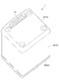
- FIG. 1 is a perspective view showing a battery pack, which is an electric storage device according to an embodiment of the present invention
- FIG. 1 is a bottom perspective view showing a battery pack, which is an electric storage device according to an embodiment of the present invention
- FIG. 1 is an exploded perspective view showing a battery pack that is an electric storage device according to an embodiment of the present invention
- FIG. BRIEF DESCRIPTION OF THE DRAWINGS FIG.
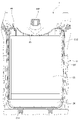
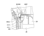
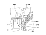
- FIG. 1 is a side cross-sectional view showing a state in which a battery pack, which is an electric storage device according to an embodiment of the present invention, is accommodated in a battery case of an electric vehicle; 1 is an enlarged front cross-sectional view of an upper portion of a battery pack, which is an electric storage device according to an embodiment of the present invention, accommodated in a battery case of an electric vehicle; FIG. 1 is an enlarged cross-sectional view of an upper rear portion of a battery pack, which is an electric storage device according to an embodiment of the present invention, accommodated in a battery case of an electric vehicle; FIG.
- FIG. 1 is a rear cross-sectional view showing a state in which a battery pack, which is an electric storage device according to an embodiment of the present invention, is accommodated in a battery case of an electric vehicle;
- FIG. 1 is an enlarged front cross-sectional view of a lower portion of a battery pack, which is an electric storage device according to an embodiment of the present invention, accommodated in a battery case of an electric vehicle;
- FIG. 2 is an enlarged cross-sectional view of the lower rear part showing how a battery pack, which is an electric storage device according to an embodiment of the present invention, is accommodated in a battery case of an electric vehicle.
- FIG. 2 is a bottom cross-sectional view showing a state in which a battery pack, which is an electric storage device according to an embodiment of the present invention, is inserted into an insertion hole of an exchange;
- FIG. 1 is a perspective view showing a battery pack 1.
- FIG. 2 is a bottom perspective view of the battery pack 1.
- FIG. FIG. 3 is an exploded perspective view showing the battery pack 1.
- the upper side the side on which the handle 42 is provided
- the opposite side the lower side shown in FIG. 1
- the lower side the opposite side
- the portable battery pack 1 as a storage device is suitably applied to, for example, a power-assisted bicycle, a portable drive power source (MPP) detachably mounted on an electric motorcycle, or the like.
- a battery pack 1 as an electric storage device includes a storage battery case 10 that forms an approximately rectangular parallelepiped exterior body, and a battery group that is housed inside the storage battery case 10 and serves as an electric storage unit.
- the external shape of the battery pack 1 is a rectangular parallelepiped, and as shown in FIG. 10, when viewed in the direction in which the battery pack 1 extends, it has a substantially rectangular shape having four vertices and four sides connecting the vertices. formed. Note that the extending direction of the battery pack 1 as a storage device is also the direction in which the battery pack 1 is attached to an electric vehicle (electrically assisted bicycle, electric motorcycle, etc.) or an exchange S as an electric power device.
- the storage battery case 10 constitutes a housing and accommodates a battery core pack (not shown) that constitutes a battery group.
- the storage battery case 10 can be made of, for example, metal such as aluminum, resin (including fiber-reinforced resin), or the like.
- the storage battery case 10 has a bottom case 24 , an outer shell case 26 , a handle body 43 , a handle cover 44 and a top cover including a top case 28 .
- the bottom case 24 is configured separately from a battery group (not shown), is arranged outside the battery group and below the battery group, has an open upper end, and has a rectangular shape in plan view. there is In addition, the connector portion 33 and the like are accommodated inside the bottom case 24 .
- the connector portion 33 is exposed to the outside of the case 12 through, for example, a through hole (not shown) formed in the bottom wall of the bottom case 24, and is used as a power supply port of the electric vehicle or for charging a battery group (not shown). It is electrically connectable to a charging device. By connecting the connector portion 33 to the power supply port or the charging device, the power supply port or the charging device and a battery group (not shown) are electrically connected via a BMU (not shown).
- the outer shell case 26 (see FIG. 1) has a rectangular cylindrical shape and covers the side surfaces of the battery group (not shown).
- the upper end of the outer shell case 26 opens upward at the upper opening 26a, and the lower end of the outer shell case 26 opens downward at the lower opening 26b.
- the inner space of the outer shell case 26 accommodates a battery group (not shown), a BMU (not shown), and the like. be.
- seal rings (not shown) are provided over the entire circumference.
- the top case 28 is configured separately from the battery group (not shown), is arranged outside the battery group and above the battery group, is a housing with an open bottom end, and has a rectangular shape in plan view. ing.
- a concave portion 281 is formed so that the hand does not easily touch the upper surface of the top case 28 when the handle 42 is gripped by the hand.
- Four corners of the top case 28 are fixed to the outer shell case 26 with bolts 282, and the bolts 282 are covered with waterproof caps 283 for preventing water from entering from the positions of the bolts 282. It is attached to the
- a handle 42 is connected to the upper surface 28a of the top case 28. As shown in FIG. The handle 42 is gripped by the user, for example, when carrying the battery pack 1 .
- the handle 42 includes a first handle portion 421 and a second handle portion 422 .
- the first handle portion 421 is arranged along the outer circumference of the upper surface 28 a of the top case 28 .
- the second handle portion 422 is arranged to extend in a direction orthogonal to the first handle portion 421 .
- the handle 42 has a handle body 43 and a handle cover 44 that covers the entire handle body 43 .
- the handle main body 43 has a planar T shape including a first main body portion 431 that constitutes the first handle portion 421 and a second main body portion 432 that constitutes the second handle portion 422. are fixed to the top case 28 by bolts 434, respectively.
- the handle cover 44 includes a first cover portion 441 forming the first handle portion 421 and a second cover portion 442 forming the second handle portion 422 .
- the central portion of the first body portion 431 has a square shape and is open in the front-rear direction.
- the first cover portion 441 of the handle cover 44 is formed with an opening 4411 having the same shape as the square-shaped opening in the central portion of the first body portion 431 .
- a battery core pack (not shown) that constitutes a battery group (not shown) has a plurality of battery cells and a plurality of cell holders that hold the battery cells.
- the battery cell is preferably a lithium ion secondary battery, it is not particularly limited to this.
- a secondary battery such as an all-solid battery, a nickel hydrogen battery, or a nickel cadmium battery may be used.
- a plurality of busbar plates are provided so as to cover the positive terminals and negative terminals of the plurality of battery cells, respectively. The busbar plates connect a predetermined number of positive terminals or negative terminals in parallel. do.
- the plurality of busbar plates are connected in series to the connector section 33 via a BMU (not shown).
- the exchange S can receive the battery pack 1 that has been used by the user and replace it with a new battery pack 1 that is being stored.
- the battery pack 1 received from the user is charged in the exchange S and stored. That is, the exchange S is also a charger having a function of charging the battery pack 1 .
- the exchange S may be a discharger having a function of discharging the electric power of the battery pack 1 in storage to the outside of the exchange S.
- the maximum outer shape of the handle cover 44 in the direction orthogonal to the vertical direction in FIG.
- the outer peripheral length L3 is formed by the portion of the side wall portion 4442 (see FIGS. 5 and 6) that protrudes most in the same direction, and the handle cover 44 protrudes in the same direction more than the side surface 261. This is longer than the maximum outer peripheral length L1 of the outer shape of the outer shell case 26 in the same direction indicated by the thick dashed line. 1 and 10, the maximum outer peripheral length L2 of the outer shape of the bottom case 24 in the direction perpendicular to the vertical direction in FIG.
- the thick portion 2442 see FIGS.
- the maximum outer circumference L2 is the longest among the maximum outer circumference L1 to the maximum outer circumference L3.
- FIG. 4 is a side sectional view showing how the battery pack 1 is accommodated in the battery case C of the electric vehicle.
- FIG. 5 is an enlarged front sectional view of the upper part of the battery pack 1 showing how the battery pack 1 is accommodated in the battery case C of the electric vehicle.
- FIG. 6 is an enlarged cross-sectional view of the upper rear part of the battery pack 1 showing how the battery pack 1 is accommodated in the battery case C of the electric vehicle.
- FIG. 7 is a rear sectional view showing how the battery pack 1 is accommodated in the battery case C of the electric vehicle.
- FIG. 8 is an enlarged front cross-sectional view of the lower portion of the battery pack 1 showing how the battery pack 1 is accommodated in the battery case C of the electric vehicle.
- FIG. 5 is an enlarged front sectional view of the upper part of the battery pack 1 showing how the battery pack 1 is accommodated in the battery case C of the electric vehicle.
- FIG. 6 is an enlarged cross-sectional view of the upper rear part of the battery pack 1 showing how
- FIG. 9 is an enlarged cross-sectional view of the lower rear portion of the battery pack 1 showing how the battery pack 1 is accommodated in the battery case C of the electric vehicle.
- FIG. 10 is a bottom cross-sectional view showing how the battery pack 1 is inserted into the insertion hole S103 of the exchange S. As shown in FIG. In FIG. 10, for the sake of convenience, the maximum perimeter lengths L1 and L3 are shown only on the left side, and illustration on the right side is omitted.
- the exchange S has an inner wall S101 forming an insertion hole S103 into which the battery pack 1 can be inserted, and the battery pack 1 is inserted into the insertion hole S103 from the bottom case 24 side.
- the insertion hole S ⁇ b>103 is formed in a tubular shape with a closed bottom, and has a square shape when viewed in cross section perpendicular to the longitudinal direction of the battery pack 1 .
- the bottom portion (not shown) is located on the front side of the paper plane shown in FIG.
- a terminal (not shown) electrically connected to the connector portion 33 is provided on the bottom (not shown) of the inner wall S101.
- One side (upper side of the inner wall S101 of the insertion hole S103 in FIG. 10) of the inner wall S101 which is rectangular in cross-section, has a shape that curves so as to be convex toward the outside of the exchange S. (the left, right, and lower sides of the inner wall S101 in FIG. 10) are linear.
- the substantially square formed by the inner peripheral surface of the inner wall S101 is the maximum outer shape of the outer shell case 26 of the battery pack 1 in the same direction.
- a space is formed between the battery pack 1 and the inner wall S101 of the insertion hole S103.
- the three straight sides of the square inner wall S101 have an insertion hole S103 formed by the inner wall S101 and the battery pack.
- a positioning rail S11 is provided that extends in the direction in which battery pack 1 is inserted (the direction parallel to the longitudinal direction of inserted battery pack 1).
- the positioning rails S11 are not provided on one side having a curved shape, but are provided one at each center of two sides adjacent to the one side (left and right sides of the inner wall S101 in FIG. 10), It is fixed to the inner wall S101.
- Two positioning rails S11 are provided on the remaining side (the lower side of the inner wall S101 in FIG. 10). 1 is fixed to the inner wall S101 so as to be positioned between adjacent outer thick-walled portions 244 described later of the bottom case 24 of the battery pack 1 in the bottom view of the battery pack 1 .
- the positioning rail S11 abuts on the outer shell case 26 of the battery pack 1 to support the battery pack 1 .
- the battery case C of the electric vehicle can accommodate the battery pack 1 and, instead of the battery pack 1, can accommodate a battery pack (not shown) having an outer shell case that is one size larger than the outer shell case 26 of the battery pack 1.
- a battery pack (not shown) having an outer shell case that is one size larger than the outer shell case 26 of the battery pack 1.
- the battery case C of the electric vehicle includes a case housing portion C11 and a case opening cylindrical portion C12.
- the case housing portion C11 has a cylindrical shape with a bottom portion that forms an insertion hole into which the battery pack 1 can be inserted.
- the case opening tubular portion C12 is fixed to the opening at the upper end of the case housing portion C11 and the inner peripheral surface in the vicinity thereof, and has a tubular shape with both ends opened.
- a terminal (not shown) is provided at the bottom of the case housing portion C11 to be electrically connected to the connector portion 33 by contacting the same.
- a stepped portion that widens the width of the case housing portion C11 upward by one step is provided at the lower portion of the side portion of the case housing portion C11 near the bottom of the case housing portion C11.
- C111 is provided.
- the peripheral portion 444 of the handle cover 44 has an upper wall portion 4441 and side wall portions 4442 .
- the side wall portion 4442 is thicker than the upper wall portion 4441 . Therefore, in a cross section taken along a horizontal plane that is parallel to a direction perpendicular to the vertical direction in FIG. The side wall portion 4442 protrudes outward (to the left in FIG. 5 and to the right in FIG. 6).
- bottom case 24 which has a rectangular shape in plan view, are configured to be thick in the longitudinal direction, which is the direction in which battery pack 1 extends. It has an outer thick portion 244 having a thick portion 2441 and a horizontal thick portion 2442 that is thick in the horizontal direction perpendicular to the longitudinal direction.
- the outer thick portion 244 is provided over a corner and two sides sandwiching the corner in the vicinity of the corner.
- the upper portion of the horizontal thick portion 2442 is provided with a step portion engaging portion 2445 that can be engaged with the step portion C111 of the battery case C of the electric vehicle. Since the step engaging portion 2445 is provided, the thickness of the horizontal thick portion 2442 becomes thicker at the step engaging portion 2445 toward the upper side.
- the battery pack 1 is accommodated in the battery case C without looseness due to the engagement of the stepped portion engaging portion 2445 with the stepped portion C111 of the battery case C.
- the positioning rail S11 abuts against the side surface 261 of the outer shell case 26, and one side of the inner wall S101 ( One side surface 261 of the outer shell case 26 (upper side of the inner wall S101 in FIG. 10) is curved so as to be convex toward the outside of the battery pack 1 (the upper side of the outer shell case 26 in FIG. 10). ), the battery pack 1 is housed in the switchboard S without looseness.
- the battery case C of the electric vehicle and the battery pack 1 which is provided to be mountable in the insertion hole S103 of the switchboard S of the charging station are in contact with the battery case C when mounted in the battery case C.
- the outer shape is formed such that the side wall portion 4442 and the horizontal thick portion 2442 which are the portions and the outer shell case 26 which is the contact portion with the exchange S when mounted on the exchange S are different.
- the contact portion is different, so that the battery pack can be inserted into the insertion hole S103.
- the battery pack 1 can be reliably supported when the battery pack 1 is inserted, and it is possible to avoid rattling and insufficient fixing surface width for fixing the battery pack 1. ⁇ .
- the outer shape when viewed in the direction in which the battery pack 1 extends, is formed in a substantially rectangular shape having four vertices and four sides connecting the vertices.
- the meat part 2442 is arranged near the vertex, and the outer shell case 26 is arranged on the side avoiding the vertex.
- the contact portion with the battery case C when attached to the battery case C and the contact portion with the exchange S when attached to the exchange S are different when viewed in the extending direction of the battery pack 1. configuration can be easily realized.
- At least three members are provided in the extending direction of the battery pack 1, Of the at least three members, the side wall portion 4442 and the horizontal thick portion 2442 are attached to the top cover (the handle body 43, the handle cover 44, and the top case 28) that constitutes the ends of the battery pack 1 in the extending direction.
- Outer shell case 26 is composed of at least three members that do not form ends in the extending direction of battery pack 1 but form an intermediate part of battery pack 1.
- the contact portion with the battery case C when attached to the battery case C and the contact portion with the exchange S when attached to the exchange S are configured differently when viewed from the side of the battery pack 1. is easily achievable.
- the maximum outer peripheral lengths L2 and L3 in the direction perpendicular to the extending direction of the battery pack 1 of the outer shape of the side wall portion 4442 and the horizontal thick portion 2442, which are members constituting the end portion, are
- the outer shape of outer shell case 26, which is a member forming the intermediate portion, is formed so as to be larger than maximum outer peripheral length L1 in the direction orthogonal to the extending direction of battery pack 1. As shown in FIG.
- the side wall portion 4442 and the horizontal thick portion 2442 are members forming one end and the other end in the extending direction of the battery pack 1, and form two ends.
- the outer shape of the horizontal thick portion 2442 forming one end has a maximum outer peripheral length L2 in the direction orthogonal to the extending direction of the battery pack 1, which is the side wall portion forming the other end.
- the outer shape of 4442 is formed so as to be longer than the maximum outer peripheral length L3 in the direction orthogonal to the extending direction of the battery pack 1 .
- the bottom case 24 is vertically below the top cover (the handle body 43, the handle cover 44, and the top case 28) when the battery pack 1 is attached to the battery case C. placed in As a result, the outer shape of the bottom case 24, which is a member on the lower side in the direction of gravity, becomes larger, and the clearance between the bottom case 24 and the case housing portion C11 becomes smaller, so that the mounting state of the battery pack 1 becomes more stable.
- the top cover (the handle body 43, the handle cover 44, and the top case 28) has a handle 42 that is gripped by the user of the battery pack 1.
- the handle 42 includes the handle body 43, It has a handle cover 44 that covers the handle body 43 , and the side wall portion 4442 is arranged on the handle cover 44 .
- the present invention is not limited to the above-described embodiments, and includes modifications, improvements, etc. within the scope of achieving the object of the present invention.
- the configurations of the capacitor, the first mounting portion of the first power device, the second mounting portion of the second power device, etc. are the same as the configurations of the battery pack 1, the battery case C, the insertion hole S103 of the exchange S, etc. in this embodiment.
- the battery pack 1 includes three members, the bottom case 24, the outer shell case 26, and the top cover (the handle body 43, the handle cover 44, and the top case 28). It only needs to have one member.
- the battery pack 1 as a storage device has been applied to, for example, a power-assisted bicycle, a portable driving power source that is detachably mounted on an electric motorcycle, etc., but is not limited to these.
- a capacitor used in an electric device having a capacitor therein may be used for a capacitor used in an electric device having a capacitor therein.
- the outer shell case 26 is made of a metal such as aluminum that is stronger and more rigid than resin
- the bottom case 24, top case 28, handle body 43, and handle cover 44 are made of resin (including fiber reinforced resin). ) and the like.
- Battery pack (capacitor) 24 ... Bottom case (member constituting one end) 26... Outer shell case (intermediate part) 28 ... Top case (member constituting the other end) 43 ... Handle main body (member constituting the other end, grip skeleton) 44 ... Handle cover (member constituting the other end, cover lid) 261... Side surface (second contact portion) 2442: Horizontal thick portion (first contact portion) 4442... Side wall portion (first contact portion) C... Battery case (first attachment part) C11...
- Case housing portion (first contacted portion) C12...Case opening tubular portion (first contacted portion) L1...Maximum outer circumference L2...Maximum outer circumference L3...Maximum outer circumference S...Switch (second power device) S103... Insertion hole (second mounting part) S11...Rail (Second contacted portion) S101... Inner wall (second contacted portion)
Landscapes
- Engineering & Computer Science (AREA)
- Power Engineering (AREA)
- Chemical & Material Sciences (AREA)
- Chemical Kinetics & Catalysis (AREA)
- Electrochemistry (AREA)
- General Chemical & Material Sciences (AREA)
- Microelectronics & Electronic Packaging (AREA)
- Aviation & Aerospace Engineering (AREA)
- Transportation (AREA)
- Mechanical Engineering (AREA)
- Manufacturing & Machinery (AREA)
- Battery Mounting, Suspending (AREA)
Abstract
Description
図1は、バッテリパック1を示す斜視図である。図2は、バッテリパック1を示す下方斜視図である。図3は、バッテリパック1を示す分解斜視図である。以下、図1に示す上側(ハンドル42が設けられている側)を上側と定義し、その反対側(図1に示す下側)を下側と定義して説明する。
蓄電器としてのバッテリパック1は、概略直方体の外装体をなす蓄電池ケース10と、蓄電池ケース10の内部に収容された蓄電部としてのバッテリ群と、を備えている。バッテリパック1の外形形状は、直方体形状であり、図10に示すように、バッテリパック1の延在方向視で、4つの頂点と、頂点同士をそれぞれ結ぶ4つの辺とを有する略矩形状に形成されている。なお、蓄電器としてのバッテリパック1の延在方向は、電力装置としての電動車両(電動アシスト自転車、電動バイク等)や交換機Sに対するバッテリパック1の装着動作方向でもある。
本実施形態では、電動車両のバッテリケースC、及び、充電ステーションの交換機Sの挿入穴S103に装着可能に設けられるバッテリパック1は、バッテリケースCに装着されたときのバッテリケースCとの当接部である側壁部4442、水平方向厚肉部2442と、交換機Sに装着されたときの交換機Sとの当接部である外殻ケース26と、が異なるように、外形形状が形成される。
例えば、蓄電器、第1電力装置の第1装着部、第2電力装置の第2装着部等の構成は、本実施形態におけるバッテリパック1、バッテリケースC、交換機Sの挿入穴S103等の構成に限定されない。従って、例えば、バッテリパック1は、ボトムケース24と、外殻ケース26と、トップカバー(ハンドル本体43、ハンドルカバー44、及び、トップケース28)との3つの部材を備えていたが、少なくとも3つの部材を備えていればよい。
24…ボトムケース(一方の端部を構成する部材)
26…外殻ケース(中間部)
28…トップケース(他方の端部を構成する部材)
43…ハンドル本体(他方の端部を構成する部材、把持骨格部)
44…ハンドルカバー(他方の端部を構成する部材、覆蓋部)
261…側面(第2当接部)
2442…水平方向厚肉部(第1当接部)
4442…側壁部(第1当接部)
C…バッテリケース(第1装着部)
C11…ケース筐体部(被第1当接部)
C12…ケース開口部筒状部(被第1当接部)
L1…最大外周長
L2…最大外周長
L3…最大外周長
S…交換機(第2電力装置)
S103…挿入穴(第2装着部)
S11…レール(被第2当接部)
S101…内壁(被第2当接部)
Claims (15)
- 第1電力装置の第1装着部、及び、第2電力装置の第2装着部に装着可能に設けられる蓄電器であって、
前記第1装着部に装着されたときの前記第1装着部との当接部である第1当接部と、
前記第2装着部に装着されたときの前記第2装着部との当接部である第2当接部と、
が異なるように、外形形状が形成される蓄電器。 - 前記蓄電器の延在方向視で、前記外形形状は4つの頂点と、該頂点同士をそれぞれ結ぶ4つの辺とを有する略矩形状に形成され、
前記第1当接部は、前記頂点の近傍に配置され、
前記第2当接部は、前記頂点を避けた前記辺に配置される請求項1に記載の蓄電器。 - 前記蓄電器の延在方向におけるそれぞれ異なる位置に配置される少なくとも3つの部材によって構成され、
前記第1当接部は、少なくとも3つの前記部材のうち、前記蓄電器の前記延在方向の端部を構成する部材に配置され、
前記第2当接部は、少なくとも3つの前記部材のうち、前記蓄電器の前記延在方向の端部を構成せず前記蓄電器の中間部を構成する部材に配置される請求項1又は請求項2に記載の蓄電器。 - 前記端部を構成する部材の前記外形形状の、前記延在方向と直交する方向における最大外周長は、前記中間部を構成する部材の前記外形形状の、前記延在方向と直交する方向における最大外周長よりも大きくなるよう前記外形形状が形成される請求項3に記載の蓄電器。
- 少なくとも3つの前記部材のうちの2つの前記部材は、前記蓄電器の前記延在方向の一方の前記端部と他方の前記端部とを構成する部材であり、
2つの前記端部を構成する部材のうち、一方の前記端部を構成する部材の前記外形形状の、前記延在方向と直交する方向における最大外周長は、他方の前記端部を構成する部材の前記外形形状の、前記延在方向と直交する方向における最大外周長よりも大きくなるように前記外形形状が形成される請求項3又は請求項4に記載の蓄電器。 - 一方の前記端部を構成する部材は、前記蓄電器が前記第1装着部に装着された状態で、他方の前記端部を構成する部材よりも鉛直方向の下方側に配置される請求項5に記載の蓄電器。
- 前記端部を構成する部材は、前記蓄電器の利用者が把持する把持部を有し、
前記把持部は、把持骨格部と前記把持骨格部を覆う覆蓋部とを有し、
前記第1当接部は、前記覆蓋部に配置される請求項3~請求項6のいずれかに記載の蓄電器。 - 前記端部を構成する部材は、前記中間部を構成する部材に対して着脱可能に設けられる請求項3~請求項7のいずれかに記載の蓄電器。
- 前記中間部を構成する部材は、前記端部を構成する部材よりも強度及び/又は剛性が高くなるよう形成される請求項3~請求項8のいずれかに記載の蓄電器。
- 前記中間部を構成する部材は、金属により構成される請求項9に記載の蓄電器。
- 前記端部を構成する部材は、樹脂により構成される請求項9又は請求項10に記載の蓄電器。
- 前記第1電力装置は、前記第1装着部に装着された前記蓄電器と電気的に接続され、前記蓄電器の電力によって駆動される駆動部を有する移動体であり、
前記第2電力装置は、前記第2装着部に装着された前記蓄電器と電気的に接続され、前記蓄電器に対して外部の電力を入力する充電部と、前記蓄電器の電力を外部に対して出力する放電部と、の少なくとも何れか一方を有する充放電装置である請求項1~請求項11のいずれかに記載の蓄電器。 - 前記充放電装置は、利用者から受領した前記蓄電器の代わりに保管中の他の蓄電器を提供する交換機能を有する交換機である請求項12に記載の蓄電器。
- 前記移動体は、前記駆動部によって駆動される車輪を有する車両である請求項12又は請求項13に記載の蓄電器。
- 蓄電器が装着される第1装着部を有する第1電力装置と、前記蓄電器又は前記蓄電器と同一形状の他の蓄電器が装着される第2装着部を有する第2電力装置と、を有する電力装置であって、
前記第1装着部は、前記蓄電器が該第1装着部に装着されたときに、前記蓄電器の外形形状の第1当接部が当接する被第1当接部を有するよう形成され、
前記第2装着部は、前記蓄電器又は前記他の蓄電部が該第2装着部に装着されたときに、前記蓄電器又は前記他の蓄電部の外形形状の前記第1当接部とは異なる第2当接部が当接する被第2当接部を有するよう形成される電力装置。
Priority Applications (2)
| Application Number | Priority Date | Filing Date | Title |
|---|---|---|---|
| JP2023502555A JP7726980B2 (ja) | 2021-02-25 | 2022-02-25 | 電力装置 |
| US18/547,880 US20240234919A9 (en) | 2021-02-25 | 2022-02-25 | Capacitor and electrical power device |
Applications Claiming Priority (2)
| Application Number | Priority Date | Filing Date | Title |
|---|---|---|---|
| JP2021029230 | 2021-02-25 | ||
| JP2021-029230 | 2021-02-25 |
Publications (1)
| Publication Number | Publication Date |
|---|---|
| WO2022181790A1 true WO2022181790A1 (ja) | 2022-09-01 |
Family
ID=83049238
Family Applications (1)
| Application Number | Title | Priority Date | Filing Date |
|---|---|---|---|
| PCT/JP2022/008021 Ceased WO2022181790A1 (ja) | 2021-02-25 | 2022-02-25 | 蓄電器及び電力装置 |
Country Status (3)
| Country | Link |
|---|---|
| US (1) | US20240234919A9 (ja) |
| JP (1) | JP7726980B2 (ja) |
| WO (1) | WO2022181790A1 (ja) |
Citations (3)
| Publication number | Priority date | Publication date | Assignee | Title |
|---|---|---|---|---|
| JP2018129281A (ja) * | 2017-02-10 | 2018-08-16 | ソニー株式会社 | バッテリー及び接続機器 |
| WO2018235204A1 (ja) * | 2017-06-21 | 2018-12-27 | 本田技研工業株式会社 | バッテリユニット |
| WO2019064721A1 (ja) * | 2017-09-29 | 2019-04-04 | 三洋電機株式会社 | 電源装置 |
Family Cites Families (4)
| Publication number | Priority date | Publication date | Assignee | Title |
|---|---|---|---|---|
| JP3424568B2 (ja) * | 1998-10-12 | 2003-07-07 | 松下電器産業株式会社 | 電池ケース保持機構およびそれを搭載した電動車両 |
| US6536536B1 (en) * | 1999-04-29 | 2003-03-25 | Stephen F. Gass | Power tools |
| US20080259525A1 (en) * | 2005-11-09 | 2008-10-23 | Maxwell Technologies, Inc. | Energy storage apparatus and article of manufacture |
| JP4859443B2 (ja) * | 2005-11-17 | 2012-01-25 | 日立オートモティブシステムズ株式会社 | 電力変換装置 |
-
2022
- 2022-02-25 JP JP2023502555A patent/JP7726980B2/ja active Active
- 2022-02-25 US US18/547,880 patent/US20240234919A9/en active Pending
- 2022-02-25 WO PCT/JP2022/008021 patent/WO2022181790A1/ja not_active Ceased
Patent Citations (3)
| Publication number | Priority date | Publication date | Assignee | Title |
|---|---|---|---|---|
| JP2018129281A (ja) * | 2017-02-10 | 2018-08-16 | ソニー株式会社 | バッテリー及び接続機器 |
| WO2018235204A1 (ja) * | 2017-06-21 | 2018-12-27 | 本田技研工業株式会社 | バッテリユニット |
| WO2019064721A1 (ja) * | 2017-09-29 | 2019-04-04 | 三洋電機株式会社 | 電源装置 |
Also Published As
| Publication number | Publication date |
|---|---|
| US20240234919A9 (en) | 2024-07-11 |
| JPWO2022181790A1 (ja) | 2022-09-01 |
| JP7726980B2 (ja) | 2025-08-20 |
| US20240136640A1 (en) | 2024-04-25 |
Similar Documents
| Publication | Publication Date | Title |
|---|---|---|
| KR101689750B1 (ko) | 배터리 팩 | |
| RU2419922C1 (ru) | Аккумуляторная батарея и аккумуляторная ручная машина с ее использованием | |
| JP6667631B2 (ja) | バッテリーパック用電装ボックス及びそれを用いたバッテリーパック構造体 | |
| US11217852B2 (en) | Battery pack | |
| JP2012146681A (ja) | 電気デバイス集合体 | |
| WO2019065257A1 (ja) | バッテリパック | |
| EP3690977B1 (en) | Battery pack | |
| JP7550644B2 (ja) | バッテリパック | |
| WO2022181790A1 (ja) | 蓄電器及び電力装置 | |
| KR101847680B1 (ko) | 배터리 팩 | |
| CN112771730A (zh) | 公连接器和具有该公连接器的收容装置 | |
| JP7002270B2 (ja) | バッテリパック | |
| JP7422787B2 (ja) | ハンドルを備えたバッテリーパック | |
| JP7307721B2 (ja) | バッテリパック | |
| JP7401647B2 (ja) | 蓄電装置 | |
| JP5084104B2 (ja) | 電気デバイス集合体 | |
| JP7480036B2 (ja) | バッテリパック | |
| JP5248781B2 (ja) | 電気デバイスモジュール及び電気デバイスモジュール集合体 | |
| CN224067807U (zh) | 电池装置以及用电设备 | |
| CN217934066U (zh) | 箱体及电池组件 | |
| CN223156240U (zh) | 电池单体、电池装置、用电装置及储能装置 | |
| JP6975605B2 (ja) | バッテリパック | |
| CN117832744B (zh) | 电池盒及充电宝 | |
| CN112531276A (zh) | 电池箱的构造 | |
| WO2019065255A1 (ja) | バッテリパック |
Legal Events
| Date | Code | Title | Description |
|---|---|---|---|
| 121 | Ep: the epo has been informed by wipo that ep was designated in this application |
Ref document number: 22759824 Country of ref document: EP Kind code of ref document: A1 |
|
| WWE | Wipo information: entry into national phase |
Ref document number: 12023552348 Country of ref document: PH Ref document number: 18547880 Country of ref document: US Ref document number: 2023502555 Country of ref document: JP |
|
| WWE | Wipo information: entry into national phase |
Ref document number: 202347063622 Country of ref document: IN |
|
| NENP | Non-entry into the national phase |
Ref country code: DE |
|
| 122 | Ep: pct application non-entry in european phase |
Ref document number: 22759824 Country of ref document: EP Kind code of ref document: A1 |