WO2022181779A1 - 車両の制動装置 - Google Patents
車両の制動装置 Download PDFInfo
- Publication number
- WO2022181779A1 WO2022181779A1 PCT/JP2022/007976 JP2022007976W WO2022181779A1 WO 2022181779 A1 WO2022181779 A1 WO 2022181779A1 JP 2022007976 W JP2022007976 W JP 2022007976W WO 2022181779 A1 WO2022181779 A1 WO 2022181779A1
- Authority
- WO
- WIPO (PCT)
- Prior art keywords
- pressure
- hydraulic pressure
- braking
- piston
- master
- Prior art date
- Legal status (The legal status is an assumption and is not a legal conclusion. Google has not performed a legal analysis and makes no representation as to the accuracy of the status listed.)
- Ceased
Links
Images





Classifications
-
- B—PERFORMING OPERATIONS; TRANSPORTING
- B60—VEHICLES IN GENERAL
- B60T—VEHICLE BRAKE CONTROL SYSTEMS OR PARTS THEREOF; BRAKE CONTROL SYSTEMS OR PARTS THEREOF, IN GENERAL; ARRANGEMENT OF BRAKING ELEMENTS ON VEHICLES IN GENERAL; PORTABLE DEVICES FOR PREVENTING UNWANTED MOVEMENT OF VEHICLES; VEHICLE MODIFICATIONS TO FACILITATE COOLING OF BRAKES
- B60T13/00—Transmitting braking action from initiating means to ultimate brake actuator with power assistance or drive; Brake systems incorporating such transmitting means, e.g. air-pressure brake systems
- B60T13/10—Transmitting braking action from initiating means to ultimate brake actuator with power assistance or drive; Brake systems incorporating such transmitting means, e.g. air-pressure brake systems with fluid assistance, drive, or release
- B60T13/12—Transmitting braking action from initiating means to ultimate brake actuator with power assistance or drive; Brake systems incorporating such transmitting means, e.g. air-pressure brake systems with fluid assistance, drive, or release the fluid being liquid
- B60T13/14—Transmitting braking action from initiating means to ultimate brake actuator with power assistance or drive; Brake systems incorporating such transmitting means, e.g. air-pressure brake systems with fluid assistance, drive, or release the fluid being liquid using accumulators or reservoirs fed by pumps
- B60T13/142—Systems with master cylinder
- B60T13/147—In combination with distributor valve
-
- B—PERFORMING OPERATIONS; TRANSPORTING
- B60—VEHICLES IN GENERAL
- B60T—VEHICLE BRAKE CONTROL SYSTEMS OR PARTS THEREOF; BRAKE CONTROL SYSTEMS OR PARTS THEREOF, IN GENERAL; ARRANGEMENT OF BRAKING ELEMENTS ON VEHICLES IN GENERAL; PORTABLE DEVICES FOR PREVENTING UNWANTED MOVEMENT OF VEHICLES; VEHICLE MODIFICATIONS TO FACILITATE COOLING OF BRAKES
- B60T8/00—Arrangements for adjusting wheel-braking force to meet varying vehicular or ground-surface conditions, e.g. limiting or varying distribution of braking force
-
- B—PERFORMING OPERATIONS; TRANSPORTING
- B60—VEHICLES IN GENERAL
- B60T—VEHICLE BRAKE CONTROL SYSTEMS OR PARTS THEREOF; BRAKE CONTROL SYSTEMS OR PARTS THEREOF, IN GENERAL; ARRANGEMENT OF BRAKING ELEMENTS ON VEHICLES IN GENERAL; PORTABLE DEVICES FOR PREVENTING UNWANTED MOVEMENT OF VEHICLES; VEHICLE MODIFICATIONS TO FACILITATE COOLING OF BRAKES
- B60T8/00—Arrangements for adjusting wheel-braking force to meet varying vehicular or ground-surface conditions, e.g. limiting or varying distribution of braking force
- B60T8/17—Using electrical or electronic regulation means to control braking
Definitions
- the present invention relates to a vehicle braking device that adjusts hydraulic pressure in wheel cylinders provided for wheels.
- Patent Document 1 describes an example of a vehicle braking device that includes a hydraulic pressure generating device and a braking actuator.
- the hydraulic pressure generator includes a master cylinder and a reservoir tank in which brake fluid is stored.
- a hydraulic pressure chamber is defined within the master cylinder, and the hydraulic pressure chamber communicates with the inside of the reservoir tank via a port.
- the master cylinder has a piston that moves forward when the amount of braking operation by the driver is increased.
- the position of the piston when no braking operation is performed is defined as the first position.
- the piston moves forward from the first position, the volume of the hydraulic chamber gradually decreases. Then, when the piston reaches the second position, the port is closed, and communication between the hydraulic pressure chamber and the inside of the reservoir tank via the port is cut off.
- the master pressure which is the hydraulic pressure in the hydraulic pressure chamber
- the wheel pressure which is the hydraulic pressure in the wheel cylinder communicating with the hydraulic pressure chamber
- the control hydraulic pressure the amount of increase in the wheel pressure due to the actuation of the brake actuator
- the port is provided with an orifice. Therefore, when the piston moves forward at a high speed due to the driver's braking operation, the orifice effect reduces the amount of brake fluid that flows from the hydraulic chamber to the reservoir tank as the volume of the hydraulic chamber changes. do. As a result, the master pressure starts increasing before the piston reaches the second position. That is, the base hydraulic pressure can be increased before the piston reaches the second position.
- a vacuum booster is adopted as a booster device that assists the driver's braking operation.
- the braking operation may not be sufficiently assisted. That is, compared to before the master pressure exceeds the hydraulic pressure corresponding to the boost pressure, after the master pressure exceeds the hydraulic pressure corresponding to the boost pressure, the assisting efficiency of the braking operation by the booster device suddenly decreases. .
- the master pressure at the timing at which the assisting efficiency suddenly changes is called an inflection point.
- the brake actuator is operated before the master pressure reaches the inflection point to increase the wheel pressure and assist the driver's braking operation.
- the master pressure or a value corresponding to the operating force may be set as the assisting hydraulic pressure.
- the sum of the base hydraulic pressure and the boosting hydraulic pressure is the wheel pressure.
- the operating force referred to here is the force input from the driver to the brake pedal.
- JP 2011-213242 A Japanese Patent No. 5217472
- a vehicle braking device for solving the above problems is a device that adjusts the wheel pressure, which is the hydraulic pressure in the wheel cylinders provided for the wheels.
- This braking device has a reservoir tank for storing brake fluid, and a master cylinder in which a fluid pressure chamber communicating with the inside of the reservoir tank via a port is provided.
- a hydraulic pressure generating device communicating with the inside of the wheel cylinder via a hydraulic pressure generating device for generating a base hydraulic pressure, which is the wheel pressure corresponding to the master pressure, which is the hydraulic pressure of the hydraulic pressure chamber, in the wheel cylinder;
- a brake actuator operable to regulate pressure and a controller for controlling the brake actuator are provided.
- the master cylinder When the brake operation member is operated to move the master cylinder in the forward direction, the master cylinder reduces the volume of the hydraulic pressure chamber.
- a piston is provided to increase the volume of the hydraulic chamber, and when the piston is positioned at the first position, the brake operating member is operated to move the piston in the forward direction, whereby the first hydraulic pressure chamber is moved forward.
- the port is closed when the piston reaches a second position located in the forward direction relative to the position, and the master pressure is increased when the piston moves in the forward direction with the port closed.
- the control device controls the amount of increase in the wheel pressure caused by the actuation of the brake actuator according to the master pressure or an operation-related force that is an operation force input to the brake operation member by the driver of the vehicle.
- An assisting process is executed to control a certain assisting hydraulic pressure. Further, in the assisting process, the control device performs reduction control for decreasing the assisting hydraulic pressure when the piston is positioned in the backward direction from the second position.
- the piston moves forward in the master cylinder.
- the master pressure may start to increase even though the piston has not reached the second position and the hydraulic pressure chamber and the inside of the reservoir tank are communicated through the port.
- a base hydraulic pressure is generated in the wheel cylinder, increasing the wheel pressure.
- the assisting hydraulic pressure is controlled by operating the brake actuator based on the operation-related force.
- the wheel pressure is the sum of the base hydraulic pressure and the boosting hydraulic pressure.
- the fluid pressure chamber communicates with the inside of the reservoir tank via the port.
- decrease control is performed to decrease and correct the assisting hydraulic pressure.
- reduction control is performed in this manner, the assisting hydraulic pressure is less likely to increase. As a result, it is possible to prevent the wheel pressure from becoming too high when the master pressure is increased before the port is closed.
- FIG. 1 is a configuration diagram showing an outline of a vehicle equipped with a braking device according to a first embodiment;
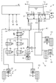
- FIG. The block diagram which shows the outline of the same braking device.
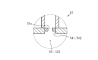
- FIG. 3 is an end view showing a part of the hydraulic pressure generator of the same braking device; 4 is a graph showing the relationship between the position of the piston and the master pressure in the hydraulic pressure generator. The figure explaining each process which the braking control part of the same braking device performs.
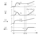
- (a) to (d) are timing charts for explaining a comparative example.
- (a) to (d) are timing charts when a driver performs a braking operation in the braking device of the first embodiment.
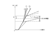
- FIG. 5 is a diagram showing the relationship between the operating force and the wheel pressure when the reference inflection point is the estimated inflection point;
- FIG. 4 is a diagram showing the relationship between the operating force and the wheel pressure when the value obtained by subtracting the correction value from the reference inflection point is set as the estimated inflection point.
- FIG. 10 is a diagram showing changes in wheel pressure when the operating force input to the brake operating member is increased in the braking device of the second embodiment; The figure explaining a part of each process which the braking control part in the braking device of 3rd Embodiment performs.
- FIG. 1 shows a vehicle 10 equipped with a braking device 40 of this embodiment.
- the vehicle 10 has a power unit 21 .
- the power unit 21 has an engine 22 and a drive motor 23 as power sources for the vehicle 10 . That is, driving force output from at least one of the engine 22 and the drive motor 23 is input to the wheels 11 . Further, when the vehicle is braked, by transmitting the rotation of the wheels 11 to the drive motor 23, the drive motor 23 can generate electric power. In this case, the vehicle 10 generates regenerative braking force, which is braking force corresponding to the amount of power generated by the drive motor 23 .
- a brake mechanism 30 is provided for each of the plurality of wheels 11 in the vehicle 10 .
- Each braking mechanism 30 has a rotating body 31 that rotates integrally with the corresponding wheel 11 , a friction material 32 , and a wheel cylinder 33 .
- the wheel pressure which is the hydraulic pressure in the wheel cylinder 33
- the pressing force which is the force pressing the friction material 32 against the rotating body 31
- the greater the pressing force the greater the frictional braking force on the wheels 11 due to the operation of the braking mechanism 30 .
- the vehicle 10 includes a hydraulic pressure generator 41 and a brake actuator 60.
- the friction braking force for each wheel 11 is adjusted by the hydraulic pressure generator 41 and the braking actuator 60 . Note that the total frictional braking force for each wheel 11 corresponds to the frictional braking force for the vehicle 10 .
- the hydraulic pressure generator 41 has a booster device 42 , a master cylinder 43 and a reservoir tank 44 .
- a braking operation member 45 is connected to the booster device 42 .
- a brake pedal can be used as the braking operation member 45 .
- the booster device 42 utilizes the boost pressure, which is the negative pressure generated by the operation of the engine 22, to boost the operation force input to the braking operation member 45 by the driver. Then, the operating force boosted by the booster device 42 is input to the master cylinder 43 .
- the master cylinder 43 has two pistons 511 and 512. Each of the pistons 511 and 512 moves in the forward direction X1 shown in FIG. 2 when an operation force is input. Assuming that the direction opposite to the forward direction X1 is the backward direction X2, of the two pistons 511 and 512, the piston 511 is located in the forward direction X1 and the piston 512 is located in the backward direction X2.
- Two hydraulic chambers 521 and 522 are provided in the master cylinder 43 . That is, two pistons 511 and 512 define respective hydraulic chambers 521 and 522 .
- the volume of the hydraulic pressure chamber 521 decreases.
- the volume of the hydraulic pressure chamber 521 increases.
- the volume of the hydraulic pressure chamber 522 decreases.
- the volume of the fluid pressure chamber 522 increases.
- the master cylinder 43 has a spring 531 that biases the piston 511 in the backward direction X2 and a spring 532 that biases the piston 512 in the backward direction X2. Therefore, when the operating force input to the master cylinder 43 is reduced, the urging forces of the springs 531 and 532 move the pistons 511 and 512 in the backward direction X2.
- the master cylinder 43 has a port 541 communicating between the fluid pressure chamber 521 and the inside of the reservoir tank 44 and a port 542 communicating between the fluid pressure chamber 522 and the inside of the reservoir tank 44 . As shown in FIG. 3, each port 541, 542 is provided with an orifice 54a.
- the operation of the braking operation member 45 by the driver is defined as "braking operation", and the position of each piston 511, 512 when no braking operation is performed is defined as “first position”.
- each port 541, 542 is not blocked. That is, the hydraulic pressure chamber 521 communicates with the reservoir tank 44 via the port 541 , and the hydraulic pressure chamber 522 communicates with the reservoir tank 44 via the port 542 .
- a braking operation is started with the pistons 511 and 512 positioned at the first position, and the pistons 511 and 512 move in the forward direction X1.
- each piston 511, 512 reaches a second position located in the forward direction X1 from the first position due to the movement of each piston 511, 512 in the forward direction X1, the port 541 is closed by the piston 511 and the port 542 is blocked by piston 512 .
- the second position is a position separated by a predetermined distance S in the forward direction X1 from the first position. Further movement of the pistons 511 and 512 in the forward direction X1 with the ports 541 and 542 closed increases the master pressure.
- Orifices 54a are provided in the ports 541 and 542 as shown in FIG. Therefore, when the driver operates the brake operating member 45 at a high speed and the pistons 511 and 512 move at a high speed in the forward direction X1, the hydraulic pressures of the hydraulic pressure chambers 521 and 522 change as the volumes of the hydraulic pressure chambers 521 and 522 change.
- the orifice effect reduces the amount of brake fluid that flows out into the reservoir tank 44 from the chambers 521 and 522 through the ports 541 and 542 .
- the master pressure in each of the hydraulic pressure chambers 521 and 522 starts increasing from the state where each of the pistons 511 and 512 is located in the backward direction X2 from the second position. That is, master pressure is generated in each of the hydraulic pressure chambers 521 and 522 .
- each of the hydraulic pressure chambers 521 and 522 communicates with the inside of the wheel cylinder 33. Therefore, when the master pressure is generated, that is, when the master pressure becomes higher than "0", the wheel pressure in each wheel cylinder 33 increases.
- a base hydraulic pressure is generated which is a wheel pressure corresponding to the master pressure. That is, the hydraulic pressure generator 41 is a device that generates the base hydraulic pressure in each wheel cylinder 33 .
- the second positions of the pistons 511 and 512 are both separated from the first positions by a predetermined distance S in the forward direction X1.
- each piston 511, 512 may have a different distance from the first position to the second position. In this case, when the distance from the first position to the second position in each piston 511, 512 reaches the greater distance, the master pressure in each hydraulic pressure chamber 521, 522 starts to increase.
- the braking actuator 60 has two systems of hydraulic circuits 611 and 612 .
- Two wheel cylinders 33 out of the plurality of wheel cylinders 33 are connected to the first hydraulic circuit 611 .
- the remaining two wheel cylinders 33 are connected to the second hydraulic circuit 612 .
- the first hydraulic circuit 611 is connected to the hydraulic chamber 521 of the master cylinder 43 .
- the second hydraulic circuit 612 is connected to the hydraulic chamber 522 of the master cylinder 43 .
- the first hydraulic circuit 611 includes a fluid path 62 connecting the fluid pressure chamber 521 and the wheel cylinder 33 and a differential pressure regulating valve 63 arranged in the fluid path 62 .
- the differential pressure regulating valve 63 is a normally open linear solenoid valve.
- the differential pressure adjusting valve 63 is driven to adjust the differential pressure between a portion closer to the master cylinder 43 than the differential pressure adjusting valve 63 and a portion closer to the wheel cylinder 33 than the differential pressure adjusting valve 63 . That is, by driving the differential pressure adjusting valve 63, the differential pressure between the hydraulic pressure chamber 521 and the inside of the wheel cylinder 33 can be adjusted.
- the first hydraulic circuit 611 is provided with a holding valve 64 that is closed when restricting the increase in wheel pressure, and a pressure reducing valve 65 that is opened when decreasing the wheel pressure.
- the first hydraulic circuit 611 is provided with the same number of holding valves 64 and pressure reducing valves 65 as the wheel cylinders 33 connected to the first hydraulic circuit 611 .
- a reservoir 66 is also connected to the first hydraulic circuit 611 . The reservoir 66 temporarily stores the brake fluid that flows out from the wheel cylinder 33 when the pressure reducing valve 65 is opened.
- the first hydraulic circuit 611 is connected to a pump 67 that supplies brake fluid to a supply fluid passage 62a that is a portion of the fluid passage 62 between the differential pressure regulating valve 63 and each wheel cylinder 33.
- the pump 67 supplies brake fluid to the fluid passage between the differential pressure regulating valve 63 and the holding valve 64 .
- the pump 67 is a pump powered by a pump motor 68 .
- the pump 67 can pump up the brake fluid in the reservoir 66 and the brake fluid in the master cylinder 43 and supply them to the supply fluid passage 62a.
- a rod fixed to the reservoir piston pushes the ball of the check valve up when the reservoir 66 is depleted of brake fluid.
- the pump 67 pumps up the brake fluid inside the master cylinder 43 .
- the reservoir piston is lowered, and the check valve blocks communication between the inside of the reservoir 66 and the inside of the master cylinder 43 . Therefore, the pump 67 pumps up the brake fluid within the reservoir 66 .
- the brake actuator 60 can control the wheel pressure by adjusting the amount of brake fluid discharged from the pump 67 and the command value (current value) to the differential pressure control valve 63 .
- control hydraulic pressure The amount of increase in wheel pressure due to actuation of the brake actuator 60 is referred to as "control hydraulic pressure.”
- vehicle 10 includes a control device 80 .
- the control device 80 has a drive control section 81 and a braking control section 82 .
- the drive control unit 81 and the braking control unit 82 can exchange information with each other.
- the drive control section 81 controls the power unit 21 . That is, the power unit 21 and the drive control section 81 correspond to the “drive device 20 ” that controls the driving force of the vehicle 10 .
- the braking control section 82 controls the braking actuator 60 . That is, in this embodiment, the braking control section 82 corresponds to a “control device” that controls the braking actuator 60 . Also, the brake control unit 82, the hydraulic pressure generator 41, and the brake actuator 60 correspond to the "brake device 40" that adjusts the wheel pressure.
- the braking control unit 82 receives detection signals from various sensors.
- sensors include a stroke sensor 91 , a master pressure sensor 92 and a negative pressure sensor 93 .
- the stroke sensor 91 detects a stroke amount St, which is the amount of operation of the braking operation member 45 by the driver, and outputs a detection signal according to the detection result.
- the master pressure sensor 92 detects the master pressure Pmc of the hydraulic pressure chamber 521 and outputs a detection signal according to the detection result.
- the negative pressure sensor 93 detects the boost pressure BP generated within the booster device 42 and outputs a detection signal according to the detection result.
- the braking control unit 82 is not limited to having a CPU and a memory for storing programs and executing software processing.
- the braking control section 82 may have any one of the following configurations (a) to (c).
- the processor includes a CPU and memory such as RAM and ROM.
- the memory stores program code or instructions configured to cause the CPU to perform processes.
- Memory, or computer-readable media includes any available media that can be accessed by a general purpose or special purpose computer.
- (b) contain one or more dedicated hardware circuits for performing various processes; Dedicated hardware circuits may include, for example, application specific integrated circuits, ie ASICs or FPGAs.
- ASIC is an abbreviation for "Application Specific Integrated Circuit”
- FPGA is an abbreviation for "Field Programmable Gate Array”.
- a processor that executes part of various processes according to a computer program, and a dedicated hardware circuit that executes the rest of the various processes.
- the drive control unit 81 is not limited to having a CPU and a memory for storing programs and executing software processing. That is, the drive control section 81 may have any one of the configurations (a) to (c) described above.
- the braking control unit 82 acquires a stroke amount acquisition process M11 for acquiring the stroke amount St.
- the braking control unit 82 acquires the stroke amount St based on the detection signal of the stroke sensor 91 in the stroke amount acquisition process M11.
- the stroke amount St corresponds to the "braking operation amount", which is the amount of operation of the braking operation member 45 by the driver. ” corresponds to
- the braking control unit 82 acquires a master pressure acquisition process M12 for acquiring the master pressure Pmc.
- the braking control unit 82 acquires the master pressure Pmc based on the detection signal of the master pressure sensor 92 in the master pressure acquisition process M12.
- the master pressure sensor value is obtained as the master pressure Pmc.
- Master pressure is the pressure generated in relation to the driver's braking operation. Therefore, it can be said that the master pressure is an operation-related force. Therefore, in the present embodiment, the master pressure acquisition process M12 can be said to be an "operation-related force acquisition process" for acquiring the master pressure Pmc as the operation-related force.
- the braking control unit 82 executes a boost pressure acquisition process M13 for acquiring the boost pressure BP.
- the braking control unit 82 acquires the boost pressure BP based on the detection signal of the negative pressure sensor 93 in the boost pressure acquisition process M13.
- the braking control unit 82 performs regenerative cooperative control M2.
- the cooperative regenerative control M2 derives the requested regenerative braking force RFTr, which is the regenerative braking force required for the drive motor 23, and the cooperative regenerative hydraulic pressure PwcA, which is the amount of increase in wheel pressure caused by the operation of the brake actuator 60.
- the braking control unit 82 executes the requested deceleration acquisition process M21 in the cooperative regeneration control M2.
- the braking control unit 82 acquires a value corresponding to the stroke amount St as the required deceleration GRq in the required deceleration acquisition process M21. That is, when the stroke amount St is less than the play determination stroke amount StA1, the braking control unit 82 acquires "0" as the required deceleration GRq.
- the braking control unit 82 acquires the prescribed value G1 as the requested deceleration GRq.
- the boundary stroke amount StA2 is larger than the determination stroke amount StA1. A value greater than "0" is set as the specified value G1.
- the braking control unit 82 acquires a larger value as the required deceleration GRq as the stroke amount St increases.
- the design value of the stroke amount St when the pistons 511 and 512 reach the second position may be set as the boundary stroke amount StA2.
- the stroke amount St when the stroke amount St is equal to the boundary stroke amount StA2, it can be determined that each of the pistons 511 and 512 is positioned at the second position.
- the stroke amount St is less than or equal to the boundary stroke amount StA2, it can be determined that the pistons 511 and 512 are positioned in the backward direction X2 relative to the second position.
- the stroke amount St is larger than the boundary stroke amount StA2 it can be determined that the pistons 511 and 512 are positioned in the forward direction X1 relative to the second position.
- the stroke amount acquisition process M11 for acquiring the stroke amount St corresponds to the “piston position acquisition process” for acquiring the positions of the pistons 511 and 512 .
- the required deceleration acquisition process M21 based on the positions of the pistons 511 and 512 acquired in the piston position acquisition process, it is determined whether or not the pistons 511 and 512 are positioned in the backward direction X2 relative to the second position. It can be said that there is Then, it can be said that the required deceleration GRq is set based on the determination result.
- the braking control unit 82 executes a conversion process M22 for converting the requested deceleration GRq into the requested braking force FRq, which is the requested value of the braking force, in the regenerative cooperative control M2. For example, when the coefficient for converting deceleration into braking force is the first conversion coefficient, the braking control unit 82 calculates the product of the requested deceleration GRq and the first conversion coefficient as the requested braking force FRq in the conversion process M22. should be derived.
- the braking control unit 82 executes a required regenerative braking force acquisition process M23 for acquiring the required regenerative braking force RFTr in the regenerative cooperative control M2.
- the braking control unit 82 selects the smaller one of the requested braking force FRq and the regenerative braking force upper limit value RFLm as the requested regenerative braking force RFTr.
- the braking control unit 82 then outputs the requested regenerative braking force RFTr to the drive control unit 81 .
- a value is set according to the performance of the drive motor 23 that applies the regenerative braking force to the vehicle 10, the amount of power stored in the storage battery that stores the power generated by the drive motor 23, and the like. be.
- the braking control unit 82 executes a subtraction process M24 for deriving the required frictional braking force FFTr in the regenerative cooperative control M2.
- a subtraction process M24 the braking control unit 82 derives a value obtained by subtracting the requested regenerative braking force RFTr from the requested braking force FRq as the requested frictional braking force FFTr.
- the braking control unit 82 executes a regenerative cooperative hydraulic pressure derivation process M25 for deriving the regenerative cooperative hydraulic pressure PwcA in the regenerative cooperative control M2.
- the braking control unit 82 converts the requested friction braking force FFTr into the regenerative cooperative hydraulic pressure PwcA in the regenerative cooperative hydraulic pressure derivation process M25.
- the braking control unit 82 may use a map showing the relationship between the frictional braking force and the wheel pressure to derive the wheel pressure corresponding to the requested frictional braking force FFTr as the regenerative cooperative hydraulic pressure PwcA.
- the braking control unit 82 performs servo correction control M3.
- the servo correction control M3 is a process for deriving the servo assisting hydraulic pressure HPwc1, which is the assisting hydraulic pressure for assisting the driver's braking operation.
- the braking control unit 82 executes an assisting gain acquisition process M31 for acquiring a value corresponding to the stroke amount St as an assisting gain ⁇ in the servo correction control M3.
- the braking control unit 82 acquires "0" as the assisting gain ⁇ when the stroke amount St is less than the first stroke amount StB1.
- the braking control unit 82 acquires "1" as the boosting gain ⁇ .
- a value larger than the first stroke amount StB1 is set as the second stroke amount StB2.
- the braking control unit 82 acquires a larger value as the assist gain ⁇ as the stroke amount St increases.
- a value slightly smaller than the boundary stroke amount StA2 is set as the first stroke amount StB1.
- a value larger than the boundary stroke amount StA2 is set as the second stroke amount StB2.
- the braking control unit 82 executes a basic value deriving process M32 for deriving the servo assisting hydraulic pressure basic value PmcB, which is the basic value of the servo assisting hydraulic pressure HPwc1.
- the braking control unit 82 derives a servo assist hydraulic pressure basic value PmcB based on the master pressure Pmc and the correction coefficient K1.
- the braking control unit 82 can derive the servo boost hydraulic pressure base value PmcB using the following relational expression (Equation 1).
- the correction coefficient K1 a value that corresponds to the design value of the servo ratio of the booster device 42 and is larger than "1" is set.
- the "servo ratio" referred to here is a value according to the design value of the boosting efficiency of the booster device 42. As shown in FIG.
- the braking control unit 82 executes a servo assisting hydraulic pressure deriving process M33 for deriving the servo assisting hydraulic pressure HPwc1.
- the braking control unit 82 derives the product of the servo boosting hydraulic pressure base value PmcB and the boosting gain ⁇ as the servo boosting hydraulic pressure HPwc1 in the servo boosting hydraulic pressure deriving process M33.
- the braking control unit 82 implements the low negative pressure assist control M4.
- the low negative pressure assisting control M4 is a process for acquiring the low negative pressure assisting hydraulic pressure HPwc2, which is the assisting hydraulic pressure for assisting the driver's braking operation when it can be estimated that the master pressure Pmc has exceeded the inflection point. is.
- the "inflection point" referred to here is the master pressure or the hydraulic pressure corresponding to the master pressure at the timing when the efficiency of assisting the braking operation by the booster device 42 suddenly changes.
- the braking control unit 82 executes a reference inflection point acquisition process M41 for acquiring the reference inflection point Ppmc in the low negative pressure assist control M4.
- the braking control unit 82 acquires a value corresponding to the boost pressure BP as the reference inflection point Ppmc.
- the braking control unit 82 acquires "0" as the reference inflection point Ppmc when the boost pressure BP is less than the first boost pressure BP1.
- the braking control unit 82 acquires the upper limit value PpmcL as the reference inflection point Ppmc when the boost pressure BP is equal to or higher than the second boost pressure BP2.
- the second boost pressure BP2 is higher than the first boost pressure BP1.
- the braking control unit 82 acquires a larger value as the reference inflection point Ppmc as the boost pressure BP increases.
- the braking control unit 82 executes an estimated inflection point derivation unit M42 for deriving an estimated inflection point PpmcA in the low negative pressure assist control M4.
- Braking control unit 82 derives, in estimated inflection point derivation unit M42, a value obtained by subtracting a predetermined correction value ⁇ from reference inflection point Ppmc as estimated inflection point PpmcA.
- a predetermined correction value ⁇ a value is set that allows the estimated inflection point PpmcA to be equal to or less than the actual value of the inflection point.
- the braking control unit 82 executes a post-correction hydraulic pressure derivation process M43 for deriving the post-correction hydraulic pressure PmcC in the low negative pressure assist control M4.
- the braking control unit 82 derives the corrected hydraulic pressure PmcC based on the value obtained by subtracting the estimated inflection point PpmcA from the master pressure Pmc. That is, the braking control unit 82 derives the larger value of the value obtained by subtracting the estimated inflection point PpmcA from the master pressure Pmc and "0" as the corrected hydraulic pressure PmcC.
- the braking control unit 82 executes a low negative pressure assisting hydraulic pressure derivation process M44 for deriving the low negative pressure assisting hydraulic pressure HPwc2.
- the braking control unit 82 derives the low negative assisting hydraulic pressure HPwc2 based on the post-correction hydraulic pressure PmcC.
- the braking control unit 82 can derive the low negative boosting hydraulic pressure HPwc2 using the following relational expression (Equation 2).
- HPwc2 (K2-1) ⁇ PmcC (Formula 2)
- the braking control unit 82 executes a command value acquisition process M5 for acquiring the total boosting hydraulic pressure HPwc as a command value for the boosting hydraulic pressure.
- the command value acquisition process M5 the braking control unit 82 acquires the sum of the servo boosting hydraulic pressure HPwc1 and the low negative pressure boosting hydraulic pressure HPwc2 as the total boosting hydraulic pressure HPwc.
- the braking control unit 82 executes a control wheel pressure acquisition process M6 for acquiring the control hydraulic pressure command value PwcTr.
- the braking control unit 82 acquires the sum of the regenerative cooperation hydraulic pressure PwcA and the total boosting hydraulic pressure HPwc as the control hydraulic pressure command value PwcTr.
- the braking control unit 82 executes an operation process M7 for operating the braking actuator 60 based on the control fluid pressure command value PwcTr.
- the braking control unit 82 operates the braking actuator 60 so that the differential pressure obtained by subtracting the master pressure Pmc from the wheel pressure becomes the control hydraulic pressure command value PwcTr.
- a A boost hydraulic pressure which is the amount of increase in wheel pressure, is set. That is, the boosting hydraulic pressure is controlled according to the master pressure Pmc. Further, the boosting hydraulic pressure is controlled according to the stroke amount St in addition to the master pressure Pmc. Therefore, in this embodiment, the servo correction control M3, the low negative pressure assisting control M4, the command value obtaining process M5, the control wheel pressure obtaining process M6, and the operation process M7 correspond to the "assisting process".
- a value corresponding to the stroke amount St is set as the assisting gain ⁇ .
- the smaller the assisting gain ⁇ that is, the smaller the stroke amount St, the smaller the value derived as the servo-assisting hydraulic pressure HPwc1. Therefore, the total assisting hydraulic pressure HPwc decreases as the stroke amount St decreases. In other words, the assisting hydraulic pressure is corrected to decrease in accordance with the stroke amount St.
- the second stroke amount StB2 which is the criterion for determining whether the boosting gain ⁇ should be "1" or less than "1"
- the boundary stroke amount StA2 is set to a design value of the stroke amount St when the pistons 511 and 512 are arranged at the second position, or a value according to the design value.
- the assist gain acquisition process M31 and the servo assist hydraulic pressure derivation process M33 correspond to "decrease control”.
- the stroke amount StB1 is set as the operation amount determination value
- the stroke amount St is equal to or less than the operation amount determination value
- the stroke amount St is larger than the operation amount determination value. It can be said that the decrease correction amount of the assisting hydraulic pressure is increased.
- the driver's braking operation starts at timing t11, so the stroke amount St increases.
- the speed of increase of the stroke amount St is high, and the speed of movement of each of the pistons 511 and 512 in the forward direction X1 is high. Therefore, due to the orifice effect of the orifices 54 a of the ports 541 and 542 , the master pressure Pmc starts to increase before the ports 541 and 542 are closed by the pistons 511 and 512 . That is, the wheel pressure PW in each wheel cylinder 33, ie, the base hydraulic pressure, begins to increase.
- the stroke amount St does not become equal to or greater than the first stroke amount StB1 due to the driver's braking operation. Therefore, when the stroke amount St stops increasing, the master pressure Pmc decreases. This is because communication between the fluid pressure chambers 521 and 522 and the inside of the reservoir tank 44 via the ports 541 and 542 is maintained.
- the assisting gain ⁇ is fixed at "1". Therefore, when the stroke amount St increases and the master pressure Pmc becomes higher than "0", even if the stroke amount St is equal to or smaller than the first stroke amount StB1, a value larger than "0" is the servo assisting hydraulic pressure HPwc1.
- the total boosting hydraulic pressure HPwc increases. That is, the wheel pressure PW becomes higher than the master pressure Pmc.
- the vehicle braking force FC which is the sum of the frictional braking force FF and the regenerative braking force RF, may become too large immediately after the driver starts the braking operation. If the vehicle braking force FC becomes too large at the initial stage of braking in this manner, the driver who performs the braking operation may decrease the stroke amount St. When the stroke amount St is reduced, the regenerative braking force RF is reduced, and the regenerative efficiency of the vehicle 10 is lowered.
- the driver's braking operation starts at timing t21, so the stroke amount St increases.
- the speed of increase of the stroke amount St is high, and the speed of movement of each of the pistons 511 and 512 in the forward direction X1 is high. Therefore, the orifice effect causes the master pressure Pmc to start increasing before the ports 541 and 542 are blocked by the pistons 511 and 512 . That is, the wheel pressure PW in each wheel cylinder 33, ie, the base hydraulic pressure, begins to increase.
- the master pressure Pmc does not exceed the estimated inflection point PpmcA during the period from timing t21 to timing t23.
- "0" is derived as the low negative pressure assisting hydraulic pressure HPwc2.
- the vehicle braking force FC is prevented from becoming too large at the initial stage of braking in this way, the driver is less likely to reduce the stroke amount St. That is, it is possible to suppress a decrease in the regeneration efficiency of the vehicle 10 as well.
- the stroke amount St is restarted to be increased by the driver's braking operation from timing t22, which is after timing t21 and before timing t23. After timing t23, the stroke amount St becomes larger than the first stroke amount StB1.
- the boosting gain ⁇ gradually increases as the stroke amount St increases.
- the servo boosting hydraulic pressure HPwc1 also gradually increases. As a result, the operation of the brake actuator 60 can increase the wheel pressure PW.
- a value less than or equal to the actual value of the inflection point is derived as the estimated inflection point PpmcA.
- the low negative pressure assisting hydraulic pressure HPwc2 can be made greater than "0" from the time when the master pressure Pmc is equal to or less than the actual value of the inflection point.
- the master pressure Pmc becomes greater than the actual value of the inflection point, it is possible to suppress the occurrence of an event in which the assisting hydraulic pressure is not generated.
- the reference inflection point Ppmc is obtained based on a map showing the relationship between the boost pressure BP and the reference inflection point Ppmc created based on the specifications of the booster device 42 .
- the booster device 42 has variations in its characteristics.
- the boost pressure BP has a detection error. Therefore, the reference inflection point Ppmc does not necessarily match the actual value PpmcR of the inflection point.
- FIG. 8 illustrates a case where the reference inflection point Ppmc is the estimated inflection point PpmcA.
- the solid line Z1 shows the transition of the wheel pressure with respect to the increase in the operating force OPbp when the reference point of inflection Ppmc is equal to the actual value PpmcR of the point of inflection. That is, the solid line Z1 indicates the ideal transition of the wheel pressure with respect to the increase in the operating force OPbp.
- a solid line Z2 shows the transition of the wheel pressure with respect to the increase in the operating force OPbp when the reference inflection point Ppmc is smaller than the actual value PpmcR of the inflection point.
- a solid line Z3 shows the transition of the wheel pressure with respect to the increase in the operating force OPbp when the reference inflection point Ppmc is greater than the actual value PpmcR of the inflection point.
- the reference inflection point Ppmc is greater than the actual value PpmcR of the inflection point
- an event occurs in which the boosting hydraulic pressure is not generated even if the master pressure Pmc becomes greater than the actual value PpmcR of the inflection point. Occur.
- the regenerative braking force upper limit value RFLm is larger than the required braking force FRq and the regenerative cooperative hydraulic pressure PwcA is "0".
- FIG. 9 shows a case where a value obtained by subtracting the correction value ⁇ from the reference inflection point Ppmc is set as the estimated inflection point PpmcA.
- the correction value ⁇ is set to a value that makes the estimated inflection point PpmcA equal to or less than the actual inflection point PpmcR. Therefore, a value greater than "0" can be set as the low negative pressure assisting hydraulic pressure HPwc2 from the time when the master pressure Pmc is equal to or lower than the actual value PpmcR of the inflection point. As a result, even if the master pressure Pmc becomes greater than the actual value PpmcR of the inflection point, it is possible to prevent the occurrence of a phenomenon in which the boosting hydraulic pressure is not generated.
- FIG. 10 A second embodiment of a vehicle braking device will be described with reference to FIGS. 10 and 11.
- FIG. 10 the parts that are different from the first embodiment will be mainly described, and the same reference numerals will be given to members that are the same as or correspond to those of the first embodiment, and redundant description will be omitted. do.
- the braking control unit 82 executes an assisting gain acquisition process M31 in the servo correction control M3.
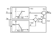
- the braking control unit 82 executes a dead zone setting process M35 for setting a dead zone AR of the master pressure Pmc in the servo correction control M3.
- the braking control unit 82 sets a value corresponding to the master pressure Pmc as the dead band AR in the dead band setting process M35. That is, the braking control unit 82 sets "0" as the dead zone AR when the master pressure Pmc is higher than the first master pressure Pmc1.
- the braking control unit 82 sets a value greater than "0" as the dead band AR.
- the braking control unit 82 sets the dead band maximum value ARmax as the dead band AR.
- a value lower than the first master pressure Pmc1 is set as the second master pressure Pmc2.
- a value greater than "0" is set as the maximum value ARmax.
- the braking control unit 82 sets the dead band AR to a smaller value as the master pressure Pmc increases.
- the maximum value of the master pressure Pmc that can be generated in the fluid pressure chambers 521 and 522 when the ports 541 and 542 are not blocked by the pistons 511 and 512, or a value corresponding to the maximum value is the maximum value of the dead zone AR. It should be set as ARmax.
- the “maximum value of the master pressure Pmc” here means the maximum value of the moving speed of the pistons 511 and 512 in the forward direction X1 assumed in terms of design, and when the pistons 511 and 512 move in the forward direction X1, This is the generated master pressure Pmc.
- the braking control unit 82 executes a subtraction process M36 in the servo correction control M3.
- the braking control unit 82 derives a value obtained by subtracting the dead band AR from the master pressure Pmc as the hydraulic pressure after subtraction PmcA.
- the braking control unit 82 derives "0" as the post-subtraction hydraulic pressure PmcA.
- the braking control unit 82 executes a basic value derivation process M32 in the servo correction control M3.
- the braking control unit 82 derives the servo boosting hydraulic pressure base value PmcB based on the post-subtraction hydraulic pressure PmcA and the correction coefficient K1.
- the braking control unit 82 can derive the servo boost hydraulic pressure base value PmcB using the following relational expression (Equation 3).
- the braking control unit 82 executes a servo assisting hydraulic pressure deriving process M33 for deriving the servo assisting hydraulic pressure HPwc1.
- a value corresponding to the master pressure Pmc is set as the dead zone AR.
- the larger the dead band AR that is, the lower the master pressure Pmc, the smaller the value derived as the post-subtraction hydraulic pressure PmcA.
- a smaller value is derived as the servo-assisting hydraulic pressure HPwc1 as the post-subtraction hydraulic pressure PmcA is smaller. Therefore, the larger the dead band AR, that is, the lower the master pressure Pmc, the smaller the value derived as the servo boosting hydraulic pressure HPwc1. That is, when the master pressure Pmc is low, it can be said that the reduction correction amount of the boosting hydraulic pressure is larger than when the master pressure Pmc is high.
- the master pressure Pmc is acquired as the operation-related force. Therefore, when the second master pressure Pmc2 is used as the force determination value, in the assisting control in the present embodiment, when the master pressure Pmc is equal to or less than the force determination value, it is compared with when the master pressure Pmc is greater than the force determination value. It can be said that the decrease correction amount of the assisting hydraulic pressure is increased.
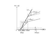
- a dashed line indicates a first transition line L1, which is a line indicating the ideal relationship between the operating force and the wheel pressure PW in terms of design.
- a second transition line L2 which is a line indicating the relationship between the operating force and the assisting hydraulic pressure in this embodiment, is indicated by a solid line.
- the master pressure Pmc reaches an inflection point.
- the estimated inflection point PpmcA is equal to the actual value of the inflection point. Therefore, the low negative pressure assisting hydraulic pressure HPwc2 obtained by executing the low negative pressure assisting control M4 becomes greater than "0". Therefore, even after the master pressure Pmc exceeds the inflection point, the wheel pressure PW can be increased according to the increase in the operating force.
- the operating force input from the driver to the brake operating member 45 may be large in the initial state of braking.
- the moving speed of each piston 511, 512 in the forward direction X1 within the master cylinder 43 is high. Therefore, in each of the hydraulic chambers 521 and 522, the master pressure Pmc is generated before the ports 541 and 542 are blocked by the pistons 511 and 512, respectively. Then, in the wheel cylinder 33, a base hydraulic pressure corresponding to the master pressure Pmc is generated.
- a dead band AR is set for the master pressure Pmc.
- the servo assisting hydraulic pressure HPwc1 becomes "0". That is, the boosting hydraulic pressure is corrected to decrease. As a result, it is possible to prevent the wheel pressure PW from becoming too high relative to the stroke amount St.
- the assisting hydraulic pressure is reduced and corrected through the setting of the dead zone AR. Therefore, the effect of suppressing the wheel pressure PW from becoming too high relative to the stroke amount St can be enhanced.
- a third embodiment of a vehicle braking device will be described with reference to FIG.
- the parts that are different from the above-described embodiments will be mainly described, and the same reference numerals will be given to members that are the same as or correspond to those of the above-described embodiments, and redundant description will be omitted. do.
- the braking control unit 82 executes an assisting gain acquisition process M31 in the servo correction control M3.
- the braking control unit 82 acquires the gain lower limit value as the assisting gain ⁇ when the stroke amount St is less than the first stroke amount StB1.
- a value greater than "0" and less than "1" is set as the gain lower limit value.
- the braking control unit 82 acquires "1" as the boosting gain ⁇ .
- the stroke amount St is greater than or equal to the first stroke amount StB1 and less than the second stroke amount StB2
- the braking control unit 82 acquires a larger value as the assist gain ⁇ as the stroke amount St increases.
- the braking control unit 82 executes a gain correction process M37 in the servo correction control M3.
- the braking control unit 82 derives a value obtained by correcting the assist gain ⁇ based on the stroke change speed dSt, which is the change speed of the stroke amount St, as the corrected assist gain ⁇ 1.
- the braking control unit 82 derives the product of the correction coefficient corresponding to the stroke change speed dSt and the assisting gain ⁇ as the post-correction assisting gain ⁇ 1.
- a smaller value can be derived as the post-correction assisting gain ⁇ 1 as the stroke change speed dSt increases.
- a value obtained by differentiating the stroke amount St with respect to time may be used as the stroke change speed dSt.
- the braking control unit 82 derives the product of the servo-assisting hydraulic pressure base value PmcB and the post-correction assisting gain ⁇ 1 as the servo-assisting hydraulic pressure HPwc1. As a result, a smaller value can be derived as the servo boosting hydraulic pressure HPwc1 as the stroke change speed dSt increases.
- a smaller value is derived as the post-correction boosting gain ⁇ 1 as the moving speed of the pistons 511 and 512 in the forward direction X1 increases. Therefore, it can be said that the higher the moving speed of the pistons 511 and 512 in the forward direction X1, the larger the reduction correction amount of the boosting hydraulic pressure.
- the master pressure is used as the operation-related force, but the operation force input to the brake operation member 45 by the driver may be used as the operation-related force.
- the sensor value of the operating force may be acquired as the operating force based on the detection signal of the operating force sensor that detects the operating force.
- an estimated master pressure may be derived by converting the operating force into a master pressure, and the estimated master pressure may be acquired as the master pressure Pmc. Even in this case, the same effects as those of the above embodiments can be obtained.
- the assisting gain ⁇ is set to "0" when the stroke amount St is less than or equal to the stroke amount StB1, but the present invention is not limited to this.
- a predetermined value greater than "0" and less than "1" may be set as the boosting gain ⁇ .
- the dead zone AR is set by executing the dead zone setting process M35 as shown in FIG. 10, it is not necessary to vary the assisting gain ⁇ according to the stroke amount St.
- the servo-assisting hydraulic pressure base value PmcB is derived as the servo-assisting hydraulic pressure HPwc1.
- a value equal to the boundary stroke amount StA2 may be set as the second stroke amount StB2.
- a value larger than the boundary stroke amount StA2 may be set as the second stroke amount StB2.
- the servo boosting hydraulic pressure HPwc1 is derived as the total boosting hydraulic pressure HPwc.
- the reduction correction similar to the servo correction control M3 may be applied to the low negative pressure assist control M4.
- the low negative pressure assisting hydraulic pressure HPwc2 may be derived from the product of the assisting gain ⁇ corresponding to the stroke amount St and the value obtained in the low negative pressure assisting hydraulic pressure deriving process M44.
- a dead band AR may be set for the master pressure Pmc in the low negative pressure assist control M4.
- the brake actuator may have a configuration different from that of the brake actuator 60 as long as it can adjust the control hydraulic pressure.
- the vehicle to which the braking device 40 is applied may be a vehicle that does not have the engine 22 as long as it has the drive motor 23 as the power source of the vehicle. In this case, a device having a vacuum pump may be adopted as the booster device 42 .
Landscapes
- Engineering & Computer Science (AREA)
- Transportation (AREA)
- Mechanical Engineering (AREA)
- Regulating Braking Force (AREA)
- Braking Systems And Boosters (AREA)
Abstract
制動装置40は、液圧発生装置41と、制動アクチュエータ60と、制動制御部82とを備える。制動制御部82は、液圧発生装置41におけるマスタシリンダ43の液圧室521,522のマスタ圧、又は、運転者から制動操作部材に入力される操作力である操作関連力に応じ、制動アクチュエータ60の作動に起因するホイール圧の増大量である助勢液圧を制御する助勢処理を実行する。制動制御部82は、助勢処理において、マスタシリンダ43のピストン511,512が第2位置よりも後退方向X2に位置する場合には、助勢液圧を減少補正する減少制御を実施する。
Description
本発明は、車輪に対して設けられているホイールシリンダ内の液圧を調整する車両の制動装置に関する。
特許文献1には、液圧発生装置と、制動アクチュエータとを備える車両の制動装置の一例が記載されている。当該制動装置において、液圧発生装置は、マスタシリンダと、ブレーキ液が貯留されているリザーバタンクとを備えている。マスタシリンダ内には液圧室が区画されており、液圧室はポートを介してリザーバタンク内と連通している。マスタシリンダは、運転者による制動操作量が増大されている場合に前進方向に移動するピストンを備えている。制動操作が行われていない場合におけるピストンの位置を第1位置とする。ピストンが第1位置に位置する状態からピストンが前進方向に移動すると、液圧室の容積が徐々に小さくなる。そして、ピストンが第2位置に達すると、ポートが閉塞され、ポートを介した液圧室とリザーバタンク内との連通が遮断される。そのため、この状態から前進方向にさらにピストンが移動すると、液圧室の液圧であるマスタ圧が高くなる。これにより、液圧室と連通するホイールシリンダ内の液圧であるホイール圧が高くなる。なお、マスタ圧の増大によって発生するホイール圧を、基礎液圧という。また、制動アクチュエータの作動によるホイール圧の増大量を、制御液圧という。
特許文献1によれば、上記ポートにはオリフィスが設けられている。そのため、運転者による制動操作に起因するピストンの前進方向への移動速度が高い場合、液圧室の容積の変化に伴って液圧室からリザーバタンクに流出するブレーキ液の量がオリフィス効果によって減少する。その結果、ピストンが第2位置に達する前からマスタ圧の増大が開始されるようになる。すなわち、ピストンが第2位置に達する前から基礎液圧を高くできる。
ところで、上記のような液圧発生装置では、運転者の制動操作を助勢するブースタ装置として、バキューム方式のブースタが採用される。この場合、ブースタ装置内の圧力室の負圧であるブースト圧があまり高くない状態で運転者が制動操作を行うと、当該制動操作を十分に助勢できないことがある。すなわち、ブースト圧に応じた液圧をマスタ圧が越える以前と比較し、ブースト圧に応じた液圧をマスタ圧が超えた以降では、ブースタ装置による制動操作の助勢効率が急に低くなってしまう。このように助勢効率が急に変わるタイミングにおけるマスタ圧を、変曲点という。
そこで、特許文献2では、マスタ圧が変曲点に達する前から、制動アクチュエータを作動させることにより、ホイール圧を増大させ、運転者の制動操作を助勢するようにしている。制動アクチュエータの作動によって運転者の制動操作を助勢するためのホイール圧の増大量を助勢液圧とした場合、マスタ圧、又は操作力に応じた値が助勢液圧として設定されることがある。この場合、基礎液圧と助勢液圧との和が、ホイール圧となる。ここでいう操作力とは、運転者からブレーキペダルに入力される力である。
特許文献1に記載の制動装置において、特許文献2に記載されているように、運転者が制動操作を行っている場合に制動アクチュエータの作動によってホイール圧を増大させ、運転者の制動操作を助勢することを考える。特許文献1に記載の制動装置では、運転者の制動操作に起因するピストンの前進方向への移動速度が高いと、ピストンによってポートが閉塞される前からマスタ圧の増大が開始される。このとき、マスタ圧の増大に応じて操作力も増大する。すなわち、ポートが閉塞される前から、制動アクチュエータの作動によってホイール圧が増大される。したがって、運転者の制動操作量に対してホイール圧が高くなりすぎ、ブレーキが効き過ぎになるおそれがある。
上記課題を解決するための車両の制動装置は、車輪に対して設けられているホイールシリンダ内の液圧であるホイール圧を調整する装置である。この制動装置は、ブレーキ液を貯留するリザーバタンク、及び、ポートを介して前記リザーバタンク内と連通する液圧室が内部に設けられているマスタシリンダを有し、前記液圧室が液路を介して前記ホイールシリンダ内と連通しており、前記液圧室の液圧であるマスタ圧に応じた前記ホイール圧である基礎液圧を前記ホイールシリンダ内に発生させる液圧発生装置と、前記ホイール圧を調整すべく作動する制動アクチュエータと、前記制動アクチュエータを制御する制御装置と、を備えている。前記マスタシリンダは、制動操作部材が操作されて前進方向に移動すると、前記液圧室の容積を小さくし、前記制動操作部材が操作されて前記前進方向の反対方向である後退方向に移動すると、前記液圧室の容積を大きくするピストンを有し、前記ピストンが第1位置に位置する状態で前記制動操作部材の操作が開始されて前記ピストンが前記前進方向に移動することにより、前記第1位置よりも前記前進方向に位置する第2位置に前記ピストンが達すると、前記ポートを閉塞し、前記ポートが閉塞された状態で前記ピストンが前記前進方向に移動すると、前記マスタ圧を増大するように構成されている。前記制御装置は、前記マスタ圧、又は、前記車両の運転者から前記制動操作部材に入力される操作力である操作関連力に応じ、前記制動アクチュエータの作動に起因する前記ホイール圧の増大量である助勢液圧を制御する助勢処理を実行するようになっている。そして、前記制御装置は、前記助勢処理において、前記ピストンが前記第2位置よりも前記後退方向に位置する場合には、前記助勢液圧を減少補正する減少制御を実施する。
運転者によって制動操作が開始された場合、マスタシリンダではピストンが前進方向に移動する。この際、ピストンの移動速度が高いと、ピストンが第2位置に達しておらず、ポートによって液圧室とリザーバタンク内とが連通していても、マスタ圧が増大され始めることがある。その結果、ホイールシリンダ内では、基礎液圧が発生し、ホイール圧が増大される。
上記構成では、制動操作が行われている場合に助勢処理が実行されると、操作関連力に基づいて制動アクチュエータが作動することにより、助勢液圧が制御される。この場合、ホイール圧は、基礎液圧と助勢液圧との和となる。
ピストンが第2位置よりも後退方向に位置する場合、ポートを介して液圧室とリザーバタンク内とが連通している。この場合、上記構成では、助勢液圧を減少補正する減少制御が実施される。このように減少制御が実施されると、助勢液圧が高くなりにくい。その結果、ポートが閉塞される前からマスタ圧が増大される場合にホイール圧が高くなりすぎることを抑制できる。
したがって、上記構成によれば、運転者の制動操作量に対してブレーキが効き過ぎになることを抑制できる。
(第1実施形態)
以下、車両の制動装置の第1実施形態を図1~図9に従って説明する。
<全体構成>
図1には、本実施形態の制動装置40を備える車両10が図示されている。車両10は、パワーユニット21を備えている。
以下、車両の制動装置の第1実施形態を図1~図9に従って説明する。
<全体構成>
図1には、本実施形態の制動装置40を備える車両10が図示されている。車両10は、パワーユニット21を備えている。
パワーユニット21は、車両10の動力源としてエンジン22及び駆動モータ23を有している。すなわち、エンジン22及び駆動モータ23のうちの少なくとも一方から出力された駆動力が車輪11に入力される。また、車両制動時には、車輪11の回転を駆動モータ23に伝えることにより、駆動モータ23に発電させることができる。この場合、車両10では、駆動モータ23の発電量に応じた制動力である回生制動力が発生する。
車両10には、複数の車輪11の各々に対して制動機構30が設けられている。各制動機構30は、対応する車輪11と一体回転する回転体31と、摩擦材32と、ホイールシリンダ33とを有している。ホイールシリンダ33内の液圧であるホイール圧が高いほど、摩擦材32を回転体31に押し付ける力である押圧力が大きくなる。押圧力が大きいほど、制動機構30の作動によって車輪11に対する摩擦制動力が大きくなる。
車両10は、液圧発生装置41と、制動アクチュエータ60とを備えている。液圧発生装置41及び制動アクチュエータ60によって、各車輪11に対する摩擦制動力が調整される。なお、各車輪11に対する摩擦制動力の合計が、車両10に対する摩擦制動力に相当する。
<液圧発生装置41の構成>
図1に示すように、液圧発生装置41は、ブースタ装置42と、マスタシリンダ43と、リザーバタンク44とを有している。ブースタ装置42には、制動操作部材45が連結されている。制動操作部材45としては、例えば、ブレーキペダルを挙げることができる。ブースタ装置42は、エンジン22の運転によって発生する負圧であるブースト圧を利用して、運転者によって制動操作部材45に入力された操作力を倍力する。そして、ブースタ装置42によって倍力された操作力がマスタシリンダ43に入力される。
図1に示すように、液圧発生装置41は、ブースタ装置42と、マスタシリンダ43と、リザーバタンク44とを有している。ブースタ装置42には、制動操作部材45が連結されている。制動操作部材45としては、例えば、ブレーキペダルを挙げることができる。ブースタ装置42は、エンジン22の運転によって発生する負圧であるブースト圧を利用して、運転者によって制動操作部材45に入力された操作力を倍力する。そして、ブースタ装置42によって倍力された操作力がマスタシリンダ43に入力される。
図2に示すように、マスタシリンダ43は、2つのピストン511,512を有している。各ピストン511,512は、操作力が入力されると、図2に示す前進方向X1に移動する。前進方向X1の反対方向を後退方向X2としたとき、2つのピストン511,512のうち、ピストン511が前進方向X1に位置し、ピストン512が後退方向X2に位置する。
マスタシリンダ43内には、2つの液圧室521,522が設けられている。すなわち、2つのピストン511,512によって各液圧室521,522が区画されている。ピストン511が前進方向X1に移動すると、液圧室521の容積が小さくなる。ピストン511が後退方向X2に移動すると、液圧室521の容積が大きくなる。また、ピストン512がピストン511に対して前進方向X1に相対移動すると、液圧室522の容積が小さくなる。ピストン512がピストン511に対して後退方向X2に相対移動すると、液圧室522の容積が大きくなる。
マスタシリンダ43は、ピストン511を後退方向X2に付勢するスプリング531と、ピストン512を後退方向X2に付勢するスプリング532とを有している。そのため、マスタシリンダ43に入力される操作力が減少されると、スプリング531,532の付勢力によって各ピストン511,512が後退方向X2に移動する。
マスタシリンダ43は、液圧室521とリザーバタンク44内とを連通するポート541と、液圧室522とリザーバタンク44内とを連通するポート542とを有している。図3に示すように、各ポート541,542内には、オリフィス54aが設けられている。
運転者が制動操作部材45を操作することを「制動操作」とし、制動操作が行われていないときの各ピストン511,512の位置を「第1位置」とする。各液圧室521,522の液圧を「マスタ圧」とする。各ピストン511,512が第1位置に位置する場合、各ポート541,542は閉塞されていない。すなわち、液圧室521はポート541を介してリザーバタンク44内と連通しているとともに、液圧室522はポート542を介してリザーバタンク44内と連通している。各ピストン511,512が第1位置に位置する状態で制動操作が開始されて各ピストン511,512が前進方向X1に移動する。この際、ポート541が閉塞されていないと、液圧室521のマスタ圧が増大されない。同様に、ポート542が閉塞されていないと、液圧室522のマスタ圧が増大されない。各ピストン511,512の前進方向X1への移動によって、第1位置よりも前進方向X1に位置する第2位置に各ピストン511,512が達すると、ポート541がピストン511によって閉塞されるとともに、ポート542がピストン512によって閉塞される。第2位置とは、第1位置から前進方向X1に所定距離Sだけ離れた位置である。各ポート541,542が閉塞された状態で各ピストン511,512が前進方向X1にさらに移動すると、マスタ圧が増大される。
図4に破線で示すように、各ピストン511,512が第2位置よりも後退方向X2に位置する場合、各液圧室521,522とリザーバタンク44内とが連通しているため、マスタ圧は「0」である。つまり、マスタ圧が発生しない。しかし、各ピストン511,512が第2位置に位置する状態から各ピストン511,512が前進方向X1に移動すると、各液圧室521,522とリザーバタンク44内との連通が遮断されるため、マスタ圧が徐々に高くなる。つまり、マスタ圧が発生する。
図3に示したようにポート541,542内にはオリフィス54aが設けられている。そのため、運転者が制動操作部材45を操作する速度が高く、各ピストン511,512の前進方向X1への移動速度が高い場合、各液圧室521,522の容積の変化に伴って各液圧室521,522からポート541,542を介してリザーバタンク44内に流出するブレーキ液の量が、オリフィス効果によって減少する。その結果、図4に実線で示すように、各ピストン511,512が第2位置よりも後退方向X2に位置する状態から各液圧室521,522でマスタ圧の増大が開始される。すなわち、各液圧室521,522でマスタ圧が発生する。
図1及び図2に示すように、各液圧室521,522は、ホイールシリンダ33内と連通している。そのため、マスタ圧が発生すると、すなわちマスタ圧が「0」よりも高くなると、各ホイールシリンダ33内のホイール圧が高くなる。マスタ圧に応じたホイール圧である基礎液圧が発生する。つまり、液圧発生装置41は、基礎液圧を各ホイールシリンダ33内に発生させる装置である。
本実施形態では、各ピストン511、512の第2位置が、共に第1位置に対して前進方向X1に所定距離Sだけ離れている。別の構成として、各ピストン511、512における第1位置から第2位置までの距離が異なる場合も考えられる。この場合、各ピストン511、512における第1位置から第2位置までの距離のうち、より離れた距離に達したとき、各液圧室521,522でマスタ圧の増大が開始される。
<制動アクチュエータ60の構成>
図2に示すように、制動アクチュエータ60は、2系統の液圧回路611,612を備えている。第1液圧回路611には、複数のホイールシリンダ33のうちの2つのホイールシリンダ33が接続されている。第2液圧回路612には、残りの2つのホイールシリンダ33が接続されている。第1液圧回路611は、マスタシリンダ43の液圧室521に接続されている。第2液圧回路612は、マスタシリンダ43の液圧室522に接続されている。
図2に示すように、制動アクチュエータ60は、2系統の液圧回路611,612を備えている。第1液圧回路611には、複数のホイールシリンダ33のうちの2つのホイールシリンダ33が接続されている。第2液圧回路612には、残りの2つのホイールシリンダ33が接続されている。第1液圧回路611は、マスタシリンダ43の液圧室521に接続されている。第2液圧回路612は、マスタシリンダ43の液圧室522に接続されている。
第1液圧回路611は、液圧室521とホイールシリンダ33とを繋ぐ液路62と、液路62に配置されている差圧調整弁63とを備えている。差圧調整弁63は、常開型のリニア電磁弁である。差圧調整弁63は、差圧調整弁63よりもマスタシリンダ43側の部分と差圧調整弁63よりもホイールシリンダ33側の部分との差圧を調整すべく駆動する。すなわち、差圧調整弁63を駆動させることにより、液圧室521とホイールシリンダ33内との間の差圧を調整できる。
第1液圧回路611には、ホイール圧の増大を規制する際に閉弁される保持弁64と、ホイール圧を減少させる際に開弁される減圧弁65とが設けられている。第1液圧回路611には、第1液圧回路611に接続されているホイールシリンダ33と同数の保持弁64及び減圧弁65が設けられている。また、第1液圧回路611には、リザーバ66が接続されている。リザーバ66には、減圧弁65を開弁させた際にホイールシリンダ33から流出したブレーキ液が一時的に貯留される。
第1液圧回路611には、液路62における差圧調整弁63と各ホイールシリンダ33との間の部分である供給液路62aにブレーキ液を供給するポンプ67が接続されている。詳しくは、ポンプ67は、差圧調整弁63と保持弁64との間の液路にブレーキ液を供給する。ポンプ67は、ポンプ用モータ68を動力源とするポンプである。ポンプ67は、リザーバ66内のブレーキ液、及び、マスタシリンダ43内のブレーキ液を汲み上げて供給液路62aに供給できる。リザーバ66がブレーキ液を蓄えていない場合、リザーバピストンに固定されたロッドがチェック弁のボールを押し上げる。これにより、リザーバ66内とマスタシリンダ43内が連通状態となる。そのため、ポンプ67は、マスタシリンダ43内のブレーキ液を汲み上げる。一方、リザーバ66がブレーキ液を蓄えている場合、リザーバピストンが下降しており、チェック弁によってリザーバ66内とマスタシリンダ43内との連通が遮断される。そのため、ポンプ67は、リザーバ66内のブレーキ液を汲み上げる。
第2液圧回路612の構造は、第1液圧回路611の構造とほぼ同一であるため、本明細書では、第2液圧回路612の構造の説明については割愛する。
本実施形態において、制動アクチュエータ60は、ポンプ67のブレーキ液の吐出量と、差圧調整弁63に対する指令値(電流値)とを調整することにより、ホイール圧を制御できる。制動アクチュエータ60の作動によるホイール圧の増大量を、「制御液圧」という。
本実施形態において、制動アクチュエータ60は、ポンプ67のブレーキ液の吐出量と、差圧調整弁63に対する指令値(電流値)とを調整することにより、ホイール圧を制御できる。制動アクチュエータ60の作動によるホイール圧の増大量を、「制御液圧」という。
<制御装置80について>
図1に示すように、車両10は、制御装置80を備えている。制御装置80は、駆動制御部81と、制動制御部82とを有している。駆動制御部81及び制動制御部82は、互いに情報の送受信が可能である。駆動制御部81は、パワーユニット21を制御する。すなわち、パワーユニット21及び駆動制御部81が、車両10の駆動力を制御する「駆動装置20」に対応する。
図1に示すように、車両10は、制御装置80を備えている。制御装置80は、駆動制御部81と、制動制御部82とを有している。駆動制御部81及び制動制御部82は、互いに情報の送受信が可能である。駆動制御部81は、パワーユニット21を制御する。すなわち、パワーユニット21及び駆動制御部81が、車両10の駆動力を制御する「駆動装置20」に対応する。
制動制御部82は、制動アクチュエータ60を制御する。すなわち、本実施形態では、制動制御部82が、制動アクチュエータ60を制御する「制御装置」に対応する。また、制動制御部82、液圧発生装置41及び制動アクチュエータ60が、ホイール圧を調整する「制動装置40」に対応する。
図2に示すように、制動制御部82には、各種のセンサから検出信号が入力される。センサとしては、例えば、ストロークセンサ91、マスタ圧センサ92及び負圧センサ93を挙げることができる。ストロークセンサ91は、運転者による制動操作部材45の操作量であるストローク量Stを検出し、その検出結果に応じた検出信号を出力する。マスタ圧センサ92は、液圧室521のマスタ圧Pmcを検出し、その検出結果に応じた検出信号を出力する。負圧センサ93は、ブースタ装置42内で発生するブースト圧BPを検出し、その検出結果に応じた検出信号を出力する。
制動制御部82は、CPUとプログラムを格納するメモリとを備えて、ソフトウェア処理を実行するものに限らない。すなわち、制動制御部82は、以下(a)~(c)の何れかの構成であればよい。
(a)コンピュータプログラムに従って各種処理を実行する一つ以上のプロセッサを備えている。プロセッサは、CPU並びに、RAM及びROMなどのメモリを含んでいる。メモリは、処理をCPUに実行させるように構成されたプログラムコード又は指令を格納している。メモリ、すなわちコンピュータ可読媒体は、汎用又は専用のコンピュータでアクセスできるあらゆる利用可能な媒体を含んでいる。
(b)各種処理を実行する一つ以上の専用のハードウェア回路を備えている。専用のハードウェア回路としては、例えば、特定用途向け集積回路、すなわちASIC又はFPGAを挙げることができる。なお、ASICは、「Application Specific Integrated Circuit」の略記であり、FPGAは、「Field Programmable Gate Array」の略記である。
(c)各種処理の一部をコンピュータプログラムに従って実行するプロセッサと、各種処理のうちの残りの処理を実行する専用のハードウェア回路とを備えている。
(a)コンピュータプログラムに従って各種処理を実行する一つ以上のプロセッサを備えている。プロセッサは、CPU並びに、RAM及びROMなどのメモリを含んでいる。メモリは、処理をCPUに実行させるように構成されたプログラムコード又は指令を格納している。メモリ、すなわちコンピュータ可読媒体は、汎用又は専用のコンピュータでアクセスできるあらゆる利用可能な媒体を含んでいる。
(b)各種処理を実行する一つ以上の専用のハードウェア回路を備えている。専用のハードウェア回路としては、例えば、特定用途向け集積回路、すなわちASIC又はFPGAを挙げることができる。なお、ASICは、「Application Specific Integrated Circuit」の略記であり、FPGAは、「Field Programmable Gate Array」の略記である。
(c)各種処理の一部をコンピュータプログラムに従って実行するプロセッサと、各種処理のうちの残りの処理を実行する専用のハードウェア回路とを備えている。
駆動制御部81は、CPUとプログラムを格納するメモリとを備えて、ソフトウェア処理を実行するものに限らない。すなわち、駆動制御部81は、上記(a)~(c)の何れかの構成であればよい。
<運転者が制動操作を行う際に制動制御部82が実行する各処理>
図5に示すように、制動制御部82は、ストローク量Stを取得するストローク量取得処理M11を取得する。制動制御部82は、ストローク量取得処理M11において、ストロークセンサ91の検出信号を基にストローク量Stを取得する。本実施形態では、ストローク量Stが、運転者による制動操作部材45の操作量である「制動操作量」に対応するため、ストローク量取得処理M11が、制動操作量を取得する「操作量取得処理」に対応する。
図5に示すように、制動制御部82は、ストローク量Stを取得するストローク量取得処理M11を取得する。制動制御部82は、ストローク量取得処理M11において、ストロークセンサ91の検出信号を基にストローク量Stを取得する。本実施形態では、ストローク量Stが、運転者による制動操作部材45の操作量である「制動操作量」に対応するため、ストローク量取得処理M11が、制動操作量を取得する「操作量取得処理」に対応する。
制動制御部82は、マスタ圧Pmcを取得するマスタ圧取得処理M12を取得する。制動制御部82は、マスタ圧取得処理M12において、マスタ圧センサ92の検出信号を基にマスタ圧Pmcを取得する。本実施形態では、マスタ圧のセンサ値がマスタ圧Pmcとして取得される。マスタ圧は、運転者の制動操作に関連して発生する圧力である。そのため、マスタ圧は、操作関連力であるといえる。よって、本実施形態では、マスタ圧取得処理M12が、マスタ圧Pmcを、操作関連力として取得する「操作関連力取得処理」といえる。
制動制御部82は、ブースト圧BPを取得するブースト圧取得処理M13を実行する。制動制御部82は、ブースト圧取得処理M13において、負圧センサ93の検出信号を基にブースト圧BPを取得する。
制動制御部82は、回生協調制御M2を実施する。回生協調制御M2は、駆動モータ23に要求する回生制動力である要求回生制動力RFTr、及び、制動アクチュエータ60の作動に起因するホイール圧の増大量である回生協調液圧PwcAを導出する。
制動制御部82は、回生協調制御M2において、要求減速度取得処理M21を実行する。制動制御部82は、要求減速度取得処理M21において、ストローク量Stに応じた値を要求減速度GRqとして取得する。すなわち、制動制御部82は、ストローク量Stが遊び判定ストローク量StA1未満である場合、「0」を要求減速度GRqとして取得する。制動制御部82は、ストローク量Stが境界ストローク量StA2以上である場合、規定値G1を要求減速度GRqとして取得する。境界ストローク量StA2は、判定ストローク量StA1よりも大きい。規定値G1として、「0」よりも大きい値が設定されている。ストローク量Stが遊び判定ストローク量StA1以上であって且つ境界ストローク量StA2未満である場合、制動制御部82は、ストローク量Stが大きいほど大きい値を要求減速度GRqとして取得する。
例えば、各ピストン511,512が第2位置に達するときのストローク量Stの設計値、又は、設計値に応じた値を境界ストローク量StA2として設定するとよい。この場合、ストローク量Stが境界ストローク量StA2と等しい場合は、各ピストン511,512が第2位置に位置すると判定できる。ストローク量Stが境界ストローク量StA2以下である場合は、各ピストン511,512が第2位置よりも後退方向X2に位置すると判定できる。ストローク量Stが境界ストローク量StA2よりも大きい場合は、各ピストン511,512が第2位置よりも前進方向X1に位置すると判定できる。すなわち、本実施形態では、ストローク量Stを取得するストローク量取得処理M11が、ピストン511,512の位置を取得する「ピストン位置取得処理」に対応する。そして、要求減速度取得処理M21では、ピストン位置取得処理で取得したピストン511,512の位置を基に、ピストン511,512が第2位置よりも後退方向X2に位置するか否かを判定しているといえる。そして、その判定結果を基に、要求減速度GRqが設定されているといえる。
制動制御部82は、回生協調制御M2において、要求減速度GRqを、制動力の要求値である要求制動力FRqに変換する変換処理M22を実行する。例えば、減速度を制動力に変換する係数を第1変換係数としたとき、制動制御部82は、変換処理M22において、要求減速度GRqと第1変換係数との積を、要求制動力FRqとして導出するとよい。
制動制御部82は、回生協調制御M2において、要求回生制動力RFTrを取得する要求回生制動力取得処理M23を実行する。制動制御部82は、要求回生制動力取得処理M23において、要求制動力FRqと、回生制動力上限値RFLmとのうち、小さい方を要求回生制動力RFTrとして選択する。そして、制動制御部82は、要求回生制動力RFTrを駆動制御部81に出力する。なお、回生制動力上限値RFLmとして、回生制動力を車両10に付与する駆動モータ23の性能、及び、駆動モータ23で発電された電力が蓄えられる蓄電池の蓄電量などに応じた値が設定される。
制動制御部82は、回生協調制御M2において、要求摩擦制動力FFTrを導出する減算処理M24を実行する。制動制御部82は、減算処理M24において、要求制動力FRqから要求回生制動力RFTrを引いた値を、要求摩擦制動力FFTrとして導出する。
制動制御部82は、回生協調制御M2において、回生協調液圧PwcAを導出する回生協調液圧導出処理M25を実行する。制動制御部82は、回生協調液圧導出処理M25において、要求摩擦制動力FFTrを回生協調液圧PwcAに変換する。例えば、制動制御部82は、摩擦制動力とホイール圧との関係を示すマップを用い、要求摩擦制動力FFTrに応じたホイール圧を回生協調液圧PwcAとして導出するとよい。
制動制御部82は、サーボ補正制御M3を実施する。サーボ補正制御M3は、運転者の制動操作を助勢するための助勢液圧であるサーボ助勢液圧HPwc1を導出するための処理である。
制動制御部82は、サーボ補正制御M3において、ストローク量Stに応じた値を助勢ゲインαとして取得する助勢ゲイン取得処理M31を実行する。助勢ゲイン取得処理M31において、制動制御部82は、ストローク量Stが第1ストローク量StB1未満である場合、「0」を助勢ゲインαとして取得する。制動制御部82は、ストローク量Stが第2ストローク量StB2以上である場合、「1」を助勢ゲインαとして取得する。第2ストローク量StB2として、第1ストローク量StB1よりも大きい値が設定されている。制動制御部82は、ストローク量Stが第1ストローク量StB1以上であって且つ第2ストローク量StB2未満である場合、ストローク量Stが大きいほど大きい値を助勢ゲインαとして取得する。このように助勢ゲインαを「0」から徐々に増大させることで、助勢制御の開始直後における制動フィーリングを向上できる。
本実施形態では、第1ストローク量StB1として、境界ストローク量StA2よりも僅かに小さい値が設定されている。また、第2ストローク量StB2として、境界ストローク量StA2よりも大きい値が設定されている。
制動制御部82は、サーボ補正制御M3において、サーボ助勢液圧HPwc1の基礎値であるサーボ助勢液圧基礎値PmcBを導出する基礎値導出処理M32を実行する。制動制御部82は、基礎値導出処理M32において、マスタ圧Pmcと補正係数K1とを基に、サーボ助勢液圧基礎値PmcBを導出する。例えば、制動制御部82は、以下の関係式(式1)を用いてサーボ助勢液圧基礎値PmcBを導出できる。なお、補正係数K1として、ブースタ装置42のサーボ比の設計値に応じた値であって且つ「1」よりも大きい値が設定されている。ここでいう「サーボ比」とは、ブースタ装置42の助勢効率の設計値に準じた値である。
PmcB=(K1-1)×Pmc …(式1)
制動制御部82は、サーボ補正制御M3において、サーボ助勢液圧HPwc1を導出するサーボ助勢液圧導出処理M33を実行する。制動制御部82は、サーボ助勢液圧導出処理M33において、サーボ助勢液圧基礎値PmcBと助勢ゲインαとの積をサーボ助勢液圧HPwc1として導出する。
制動制御部82は、サーボ補正制御M3において、サーボ助勢液圧HPwc1を導出するサーボ助勢液圧導出処理M33を実行する。制動制御部82は、サーボ助勢液圧導出処理M33において、サーボ助勢液圧基礎値PmcBと助勢ゲインαとの積をサーボ助勢液圧HPwc1として導出する。
制動制御部82は、低負圧助勢制御M4を実施する。低負圧助勢制御M4は、マスタ圧Pmcが変曲点を越えたと推測できる場合に運転者の制動操作を助勢するための助勢液圧である低負圧助勢液圧HPwc2を取得するための処理である。ここでいう「変曲点」とは、ブースタ装置42による制動操作の助勢効率が急に変わるタイミングにおけるマスタ圧又は当該マスタ圧に応じた液圧である。
制動制御部82は、低負圧助勢制御M4において、基準変曲点Ppmcを取得する基準変曲点取得処理M41を実行する。制動制御部82は、基準変曲点取得処理M41において、ブースト圧BPに応じた値を基準変曲点Ppmcとして取得する。図5に示す、ブースト圧BPと基準変曲点Ppmcとの関係を示すマップは、液圧発生装置41におけるブースタ装置42の諸元に基づいて作成されたものである。制動制御部82は、ブースト圧BPが第1ブースト圧BP1未満である場合、「0」を基準変曲点Ppmcとして取得する。制動制御部82は、ブースト圧BPが第2ブースト圧BP2以上である場合、上限値PpmcLを基準変曲点Ppmcとして取得する。第2ブースト圧BP2は、第1ブースト圧BP1よりも大きい。制動制御部82は、ブースト圧BPが第1ブースト圧BP1以上であって且つ第2ブースト圧BP2未満である場合、ブースト圧BPが大きいほど大きい値を基準変曲点Ppmcとして取得する。
制動制御部82は、低負圧助勢制御M4において、推定変曲点PpmcAを導出する推定変曲点導出部M42を実行する。制動制御部82は、推定変曲点導出部M42において、基準変曲点Ppmcから所定の補正値βを引いた値を推定変曲点PpmcAとして導出する。補正値βとして、推定変曲点PpmcAを変曲点の実値以下とできるような値が設定されている。
制動制御部82は、低負圧助勢制御M4において、補正後液圧PmcCを導出する補正後液圧導出処理M43を実行する。制動制御部82は、補正後液圧導出処理M43において、マスタ圧Pmcから推定変曲点PpmcAを引いた値を基に、補正後液圧PmcCを導出する。すなわち、制動制御部82は、マスタ圧Pmcから推定変曲点PpmcAを引いた値と、「0」とのうち、大きい方の値を補正後液圧PmcCとして導出する。
制動制御部82は、低負圧助勢制御M4において、低負圧助勢液圧HPwc2を導出する低負圧助勢液圧導出処理M44を実行する。制動制御部82は、低負圧助勢液圧導出処理M44において、補正後液圧PmcCを基に、低負圧助勢液圧HPwc2を導出する。例えば、制動制御部82は、以下の関係式(式2)を用いて低負圧助勢液圧HPwc2を導出できる。
HPwc2=(K2-1)×PmcC …(式2)
制動制御部82は、助勢液圧の指令値として総助勢液圧HPwcを取得する指令値取得処理M5を実行する。制動制御部82は、指令値取得処理M5において、サーボ助勢液圧HPwc1と低負圧助勢液圧HPwc2との和を、総助勢液圧HPwcとして取得する。
制動制御部82は、助勢液圧の指令値として総助勢液圧HPwcを取得する指令値取得処理M5を実行する。制動制御部82は、指令値取得処理M5において、サーボ助勢液圧HPwc1と低負圧助勢液圧HPwc2との和を、総助勢液圧HPwcとして取得する。
制動制御部82は、制御液圧指令値PwcTrを取得する制御ホイール圧取得処理M6を実行する。制動制御部82は、制御ホイール圧取得処理M6において、回生協調液圧PwcAと総助勢液圧HPwcとの和を、制御液圧指令値PwcTrとして取得する。
制動制御部82は、制御液圧指令値PwcTrに基づいて制動アクチュエータ60を作動させる操作処理M7を実行する。制動制御部82は、ホイール圧からマスタ圧Pmcを引いた値である差圧が制御液圧指令値PwcTrとなるように、制動アクチュエータ60を作動させる。
本実施形態では、サーボ補正制御M3で取得したサーボ助勢液圧HPwc1と、低負圧助勢制御M4で取得した低負圧助勢液圧HPwc2とを基に、運転者の制動操作を助勢するためのホイール圧の増大量である助勢液圧を設定している。すなわち、マスタ圧Pmcに応じ、助勢液圧が制御される。また、マスタ圧Pmcに加えてストローク量Stに応じ、助勢液圧が制御される。したがって、本実施形態では、サーボ補正制御M3、低負圧助勢制御M4、指令値取得処理M5、制御ホイール圧取得処理M6及び操作処理M7が、「助勢処理」に対応する。
また、助勢ゲイン取得処理M31では、ストローク量Stに応じた値が助勢ゲインαとして設定される。そして、サーボ助勢液圧導出処理M33では、助勢ゲインαが小さいほど、すなわちストローク量Stが小さいほど、小さい値がサーボ助勢液圧HPwc1として導出される。そのため、総助勢液圧HPwcは、ストローク量Stが小さいほど小さくなる。言い換えると、ストローク量Stに応じて、助勢液圧を減少補正している。
ここで、助勢ゲインαを「1」とするか「1」未満とするかの判断基準である第2ストローク量StB2は、上記境界ストローク量StA2よりも大きい。境界ストローク量StA2は、各ピストン511,512が第2位置に配置する場合のストローク量Stの設計値、又は当該設計値に応じた値が設定されている。
そのため、助勢処理では、各ピストン511,512が第2位置よりも後退方向X2に位置する場合には、助勢液圧を減少補正する「減少制御」が実施されるといえる。具体的には、助勢ゲイン取得処理M31及びサーボ助勢液圧導出処理M33が、「減少制御」に対応する。また、上記第1ストローク量StB1を操作量判定値としたとき、助勢制御では、ストローク量Stが操作量判定値以下である場合、ストローク量Stが操作量判定値よりも大きい場合と比較して助勢液圧の減少補正量を大きくしているといえる。
<第1実施形態における作用及び効果>
図6及び図7を参照し、運転者が制動操作部材45を操作する速度が高く、急制動を運転者が要求している場合の作用及び効果について説明する。ここで、制動操作によって発生するマスタ圧Pmcよりも推定変曲点PpmcAが小さくならない程度にブースト圧BPが高い状態であるとする。また、要求制動力FRqよりも回生制動力上限値RFLmが大きく、回生協調液圧PwcAが「0」であるとする。
図6及び図7を参照し、運転者が制動操作部材45を操作する速度が高く、急制動を運転者が要求している場合の作用及び効果について説明する。ここで、制動操作によって発生するマスタ圧Pmcよりも推定変曲点PpmcAが小さくならない程度にブースト圧BPが高い状態であるとする。また、要求制動力FRqよりも回生制動力上限値RFLmが大きく、回生協調液圧PwcAが「0」であるとする。
はじめに、図6を参照し、比較例について説明する。比較例では、減少制御が実施されない。すなわち、ストローク量Stの大きさに拘わらず、「1」が助勢ゲインαとして設定される。
図6(a),(b),(c),(d)に示すように、タイミングt11から運転者の制動操作が開始されるため、ストローク量Stが増大する。図6に示す比較例では、ストローク量Stの増大速度が高く、各ピストン511,512の前進方向X1への移動速度が高い。そのため、各ポート541,542のオリフィス54aによるオリフィス効果によって、ポート541,542がピストン511,512に閉塞される前からマスタ圧Pmcが増大し始める。すなわち、各ホイールシリンダ33内のホイール圧PW、すなわち基礎液圧が増大し始める。
なお、比較例では、図6(c)に示すように、運転者の制動操作によってストローク量Stが第1ストローク量StB1以上になることはない。そのため、ストローク量Stの増大が停止されると、マスタ圧Pmcが減少する。これは、ポート541,542を介した液圧室521,522とリザーバタンク44内との連通が維持されているためである。
比較例では、助勢ゲインαが「1」に固定されている。そのため、ストローク量Stが大きくなってマスタ圧Pmcが「0」よりも高くなると、ストローク量Stが第1ストローク量StB1以下であっても、「0」よりも大きい値が、サーボ助勢液圧HPwc1として導出されるようになる。その結果、「0」がサーボ助勢液圧HPwc1として導出される場合と比較し、総助勢液圧HPwcが大きくなる。つまり、ホイール圧PWが、マスタ圧Pmcよりも高くなる。
その結果、運転者による制動操作の開始直後において、摩擦制動力FFと回生制動力RFとの和である車両制動力FCが大きくなりすぎるおそれがある。このように制動初期に車両制動力FCが大きくなりすぎると、制動操作を行う運転者は、ストローク量Stを減少させるおそれがある。ストローク量Stが減少されると、回生制動力RFが減少され、車両10の回生効率が低下してしまう。
次に、図7を参照し、本実施形態における作用及び効果について説明する。
図7(a),(b),(c),(d)に示すように、タイミングt21から運転者の制動操作が開始されるため、ストローク量Stが増大する。図7に示す例でも、比較例と同様に、ストローク量Stの増大速度が高く、各ピストン511,512の前進方向X1への移動速度が高い。そのため、オリフィス効果によって、ポート541,542がピストン511,512に閉塞される前からマスタ圧Pmcが増大し始める。すなわち、各ホイールシリンダ33内のホイール圧PW、すなわち基礎液圧が増大し始める。
図7(a),(b),(c),(d)に示すように、タイミングt21から運転者の制動操作が開始されるため、ストローク量Stが増大する。図7に示す例でも、比較例と同様に、ストローク量Stの増大速度が高く、各ピストン511,512の前進方向X1への移動速度が高い。そのため、オリフィス効果によって、ポート541,542がピストン511,512に閉塞される前からマスタ圧Pmcが増大し始める。すなわち、各ホイールシリンダ33内のホイール圧PW、すなわち基礎液圧が増大し始める。
タイミングt21から後述するタイミングt23までの期間では、ストローク量Stは第1ストローク量StB1以下である。そのため、当該期間では、助勢ゲインαとして「0」が設定される。その結果、マスタ圧Pmcが「0」よりも高くなっても、「0」がサーボ助勢液圧HPwc1として導出される。
さらに、図7に示す例では、タイミングt21からタイミングt23までの期間において、マスタ圧Pmcが推定変曲点PpmcAよりも大きくならない。その結果、低負圧助勢液圧HPwc2として「0」が導出される。
したがって、総助勢液圧HPwcとして「0」が導出される。これにより、各ピストン511,512の前進方向X1への移動速度が高いためにポート541,542がピストン511,512によって閉塞される前からマスタ圧Pmcが増大される場合に、ホイール圧PWが高くなりすぎることを抑制できる。よって、本実施形態では、ストローク量Stに対してブレーキが効き過ぎになることを抑制できる。
このように制動初期において車両制動力FCが大きくなりすぎることが抑制されると、運転者がストローク量Stを減少させる可能性が低くなる。すなわち、車両10の回生効率が低下することも抑制できる。
なお、図7に示す例では、タイミングt21よりも後であって且つタイミングt23よりも前のタイミングt22から、運転者の制動操作によってストローク量Stの増大が再開される。そして、タイミングt23以降では、ストローク量Stが第1ストローク量StB1よりも大きくなる。これにより、ストローク量Stが増大するにつれ徐々に助勢ゲインαが大きくなる。すると、サーボ助勢液圧HPwc1もまた徐々に大きくなる。その結果、制動アクチュエータ60の作動によってホイール圧PWを増大させることができる。
ちなみに、タイミングt23以降において、ストローク量Stが第2ストローク量StB2に達すると、助勢ゲインαが「1」となる。その後においてストローク量Stの増大が継続しても、助勢ゲインαが「1」である状態が保持される。
本実施形態では、以下に示す効果をさらに得ることができる。
(1-1)本実施形態では、ストローク量Stが第1ストローク量StB1以下である場合には、ストローク量Stが第1ストローク量StB1よりも大きい場合と比較して小さい値を助勢ゲインαとして導出している。これにより、ストローク量Stが第1ストローク量StB1以下である場合には、ストローク量Stが第1ストローク量StB1よりも大きい場合と比較し、助勢処理の実行時における助勢液圧の減少補正量が大きくなる。これにより、ストローク量Stが比較的小さい段階で、助勢液圧が高くなりすぎることを抑制できる。
(1-1)本実施形態では、ストローク量Stが第1ストローク量StB1以下である場合には、ストローク量Stが第1ストローク量StB1よりも大きい場合と比較して小さい値を助勢ゲインαとして導出している。これにより、ストローク量Stが第1ストローク量StB1以下である場合には、ストローク量Stが第1ストローク量StB1よりも大きい場合と比較し、助勢処理の実行時における助勢液圧の減少補正量が大きくなる。これにより、ストローク量Stが比較的小さい段階で、助勢液圧が高くなりすぎることを抑制できる。
(1-2)本実施形態では、推定変曲点PpmcAとして、変曲点の実値以下の値が導出されるようになっている。これにより、マスタ圧Pmcが変曲点の実値以下である時期から、低負圧助勢液圧HPwc2を「0」よりも大きくできる。これにより、マスタ圧Pmcが変曲点の実値よりも大きくなっても、助勢液圧が発生しない事象の発生を抑制できる。
低負圧助勢制御において、基準変曲点Ppmcは、ブースタ装置42の諸元に基づいて作成されたブースト圧BPと基準変曲点Ppmcとの関係を示すマップを基に取得される。ブースタ装置42には、その特性にばらつきがある。また、ブースト圧BPにも検出誤差がある。そのため、基準変曲点Ppmcが変曲点の実値PpmcRと一致するとは限らない。
ここで、図8には、基準変曲点Ppmcを推定変曲点PpmcAとする場合が図示されている。図8において、実線Z1は、基準変曲点Ppmcが変曲点の実値PpmcRと等しい場合における操作力OPbpの増大に対するホイール圧の推移が図示されている。すなわち、実線Z1は、操作力OPbpの増大に対するホイール圧の理想的な推移を示している。実線Z2は、基準変曲点Ppmcが変曲点の実値PpmcRよりも小さい場合における操作力OPbpの増大に対するホイール圧の推移が図示されている。実線Z3は、基準変曲点Ppmcが変曲点の実値PpmcRよりも大きい場合における操作力OPbpの増大に対するホイール圧の推移が図示されている。図8に示すように、基準変曲点Ppmcが変曲点の実値PpmcRよりも大きい場合、マスタ圧Pmcが変曲点の実値PpmcRよりも大きくなっても助勢液圧が発生しない事象が発生する。なお、図8において、要求制動力FRqよりも回生制動力上限値RFLmが大きく、回生協調液圧PwcAが「0」であるとする。
図9には、基準変曲点Ppmcから補正値βを引いた値を推定変曲点PpmcAとする場合が図示されている。本実施形態では、推定変曲点PpmcAが変曲点の実値PpmcR以下となるような値が補正値βに設定されている。そのため、マスタ圧Pmcが変曲点の実値PpmcR以下である時期から、低負圧助勢液圧HPwc2として「0」よりも大きい値を設定できる。これにより、マスタ圧Pmcが変曲点の実値PpmcRよりも大きくなっても助勢液圧が発生しない事象が発生することを抑制できる。
(第2実施形態)
車両の制動装置の第2実施形態を図10及び図11に従って説明する。以下の説明においては、第1実施形態と相違している部分について主に説明するものとし、第1実施形態と同一又は相当する部材構成には同一符号を付して重複説明を省略するものとする。
車両の制動装置の第2実施形態を図10及び図11に従って説明する。以下の説明においては、第1実施形態と相違している部分について主に説明するものとし、第1実施形態と同一又は相当する部材構成には同一符号を付して重複説明を省略するものとする。
<サーボ補正制御M3について>
図10を参照し、本実施形態において、制動制御部82が実行するサーボ補正制御M3について説明する。
図10を参照し、本実施形態において、制動制御部82が実行するサーボ補正制御M3について説明する。
制動制御部82は、サーボ補正制御M3において、助勢ゲイン取得処理M31を実行する。
制動制御部82は、サーボ補正制御M3において、マスタ圧Pmcの不感帯ARを設定する不感帯設定処理M35を実行する。制動制御部82は、不感帯設定処理M35において、マスタ圧Pmcに応じた値を不感帯ARとして設定する。すなわち、制動制御部82は、マスタ圧Pmcが第1マスタ圧Pmc1よりも高い場合には「0」を不感帯ARとして設定する。制動制御部82は、マスタ圧Pmcが第1マスタ圧Pmc1以下である場合には「0」よりも大きい値を不感帯ARとして設定する。例えば、制動制御部82は、マスタ圧Pmcが第2マスタ圧Pmc2以下である場合には不感帯の最大値ARmaxを不感帯ARとして設定する。第2マスタ圧Pmc2として、第1マスタ圧Pmc1よりも低い値が設定されている。最大値ARmaxとして、「0」よりも大きい値が設定されている。また、制動制御部82は、マスタ圧Pmcが第2マスタ圧Pmc2よりも高く、且つ第1マスタ圧Pmc1以下である場合、マスタ圧Pmcが高いほど小さい値が不感帯ARとして設定される。
制動制御部82は、サーボ補正制御M3において、マスタ圧Pmcの不感帯ARを設定する不感帯設定処理M35を実行する。制動制御部82は、不感帯設定処理M35において、マスタ圧Pmcに応じた値を不感帯ARとして設定する。すなわち、制動制御部82は、マスタ圧Pmcが第1マスタ圧Pmc1よりも高い場合には「0」を不感帯ARとして設定する。制動制御部82は、マスタ圧Pmcが第1マスタ圧Pmc1以下である場合には「0」よりも大きい値を不感帯ARとして設定する。例えば、制動制御部82は、マスタ圧Pmcが第2マスタ圧Pmc2以下である場合には不感帯の最大値ARmaxを不感帯ARとして設定する。第2マスタ圧Pmc2として、第1マスタ圧Pmc1よりも低い値が設定されている。最大値ARmaxとして、「0」よりも大きい値が設定されている。また、制動制御部82は、マスタ圧Pmcが第2マスタ圧Pmc2よりも高く、且つ第1マスタ圧Pmc1以下である場合、マスタ圧Pmcが高いほど小さい値が不感帯ARとして設定される。
例えば、ポート541,542がピストン511,512によって閉塞されていない状態で液圧室521,522に発生しうるマスタ圧Pmcの最大値、又は当該最大値に応じた値を、不感帯ARの最大値ARmaxとして設定するとよい。ここでいう「マスタ圧Pmcの最大値」とは、設計の上で想定されるピストン511,512の前進方向X1への移動速度の最大値でピストン511,512が前進方向X1に移動する際に発生するマスタ圧Pmcである。また、不感帯ARの最大値ARmax以上の値を第2マスタ圧Pmc2として設定するとよい。
制動制御部82は、サーボ補正制御M3において、減算処理M36を実行する。制動制御部82は、減算処理M36において、マスタ圧Pmcから不感帯ARを引いた値を、減算後液圧PmcAとして導出する。この際、制動制御部82は、マスタ圧Pmcから不感帯ARを引いた値が負である場合、「0」を減算後液圧PmcAとして導出する。
制動制御部82は、サーボ補正制御M3において、基礎値導出処理M32を実行する。制動制御部82は、基礎値導出処理M32において、減算後液圧PmcAと補正係数K1とを基に、サーボ助勢液圧基礎値PmcBを導出する。例えば、制動制御部82は、以下の関係式(式3)を用いてサーボ助勢液圧基礎値PmcBを導出できる。
PmcB=(K1-1)×PmcA …(式3)
制動制御部82は、サーボ補正制御M3において、サーボ助勢液圧HPwc1を導出するサーボ助勢液圧導出処理M33を実行する。
制動制御部82は、サーボ補正制御M3において、サーボ助勢液圧HPwc1を導出するサーボ助勢液圧導出処理M33を実行する。
本実施形態において、不感帯設定処理M35では、マスタ圧Pmcに応じた値が不感帯ARとして設定される。減算処理M36では、不感帯ARが大きいほど、すなわちマスタ圧Pmcが低いほど、小さい値が減算後液圧PmcAとして導出される。そして、サーボ助勢液圧導出処理M33では、減算後液圧PmcAが小さいほど小さい値が、サーボ助勢液圧HPwc1として導出される。よって、不感帯ARが大きいほど、すなわちマスタ圧Pmcが低いほど小さい値が、サーボ助勢液圧HPwc1として導出される。つまり、マスタ圧Pmcが低い場合には、マスタ圧Pmcが高い場合よりも助勢液圧の減少補正量が大きくなるといえる。
上記第1実施形態で説明したように、マスタ圧Pmcが操作関連力として取得される。そのため、第2マスタ圧Pmc2を力判定値としたとき、本実施形態では、助勢制御では、マスタ圧Pmcが力判定値以下である場合、マスタ圧Pmcが力判定値よりも大きい場合と比較して助勢液圧の減少補正量を大きくしているといえる。
<第2の実施形態における作用及び効果>
図11を参照し、上記サーボ補正制御M3が実施された際におけるホイール圧PW、より詳しくは助勢液圧の推移について説明する。なお、要求制動力FRqよりも回生制動力上限値RFLmが大きく、回生協調液圧PwcAが「0」であるとする。
図11を参照し、上記サーボ補正制御M3が実施された際におけるホイール圧PW、より詳しくは助勢液圧の推移について説明する。なお、要求制動力FRqよりも回生制動力上限値RFLmが大きく、回生協調液圧PwcAが「0」であるとする。
運転者から制動操作部材45に入力される操作力が増大されると、図11に示す例では、操作力が第1操作力OPbp1に達すると、マスタ圧Pmcが増大され始める。この際、マスタ圧Pmcが不感帯AR以下であると、減算後液圧PmcAが「0」となるため、サーボ助勢液圧HPwc1が「0」になる。すなわち、マスタ圧Pmcが不感帯AR以下である場合、助勢液圧を発生させるために制動アクチュエータ60が作動することはない。これにより、制動初期において、ホイール圧PWが高くなりすぎることを抑制でき、ひいてはブレーキが効き過ぎることを抑制できる。
図11に示す例では、操作力が第2操作力OPbp2よりも大きくなると、操作力の増大につれて不感帯ARが小さくなる。これにより、減算後液圧PmcAが「0」よりも大きくなると、サーボ助勢液圧HPwc1が「0」よりも大きくなる。すると、総助勢液圧HPwcも大きくなるため、制動アクチュエータ60の作動に起因してホイール圧PWの増大が助勢されるようになる。すなわち、助勢液圧が増大される。
なお、図11において、設計の上で理想とする操作力とホイール圧PWとの関係を示す線である第1推移線L1が破線で示されている。また、本実施形態における操作力と助勢液圧との関係を示す線である第2推移線L2が実線で示されている。操作力が第2操作力OPbp2よりも大きくなった以降では、不感帯ARが小さくなるため、第2推移線L2が第1推移線L1に徐々に接近する。そして、操作力が第3操作力OPbp3に達すると、不感帯ARが「0」となるため、第1推移線L1に第2推移線L2が重なる。なお、第2操作力OPbp2に対応するマスタ圧が第2マスタ圧Pmc2となり、第3操作力OPbp3に対応するマスタ圧が第1マスタ圧Pmc1となる。
その後、操作力の増大に伴って操作力が第4操作力OPbp4に達すると、マスタ圧Pmcが変曲点に達する。図11に示す例では、推定変曲点PpmcAが変曲点の実値と等しい。そのため、低負圧助勢制御M4の実施によって取得される低負圧助勢液圧HPwc2が「0」よりも大きくなる。そのため、マスタ圧Pmcが変曲点を越えた以降でも操作力の増大に応じてホイール圧PWを増大させることができる。
運転者が急制動を要求している場合、制動初期の状態において、制動操作部材45に運転者から入力される操作力が大きいことがある。この場合、当然、マスタシリンダ43内において各ピストン511,512の前進方向X1への移動速度が高い。そのため、各液圧室521,522では、ポート541,542がピストン511,512によって閉塞される前からマスタ圧Pmcが発生する。すると、ホイールシリンダ33内では、マスタ圧Pmcに応じた基礎液圧が発生する。
本実施形態では、マスタ圧Pmcに対して不感帯ARが設定される。そして、図11に示したようにマスタ圧Pmcが不感帯AR以下である場合、サーボ助勢液圧HPwc1は「0」になる。すなわち、助勢液圧が減少補正される。その結果、ストローク量Stに対してホイール圧PWが高くなりすぎることを抑制できる。
すなわち、本実施形態では、助勢ゲインαの設定に加え、不感帯ARの設定を通じて、助勢液圧を減少補正している。そのため、ストローク量Stに対してホイール圧PWが高くなりすぎることの抑制効果をより高くできる。
(第3実施形態)
車両の制動装置の第3実施形態を図12に従って説明する。以下の説明においては、上記各実施形態と相違している部分について主に説明するものとし、上記各実施形態と同一又は相当する部材構成には同一符号を付して重複説明を省略するものとする。
車両の制動装置の第3実施形態を図12に従って説明する。以下の説明においては、上記各実施形態と相違している部分について主に説明するものとし、上記各実施形態と同一又は相当する部材構成には同一符号を付して重複説明を省略するものとする。
図12に示すように、制動制御部82は、サーボ補正制御M3において、助勢ゲイン取得処理M31を実行する。本実施形態では、助勢ゲイン取得処理M31において、制動制御部82は、ストローク量Stが第1ストローク量StB1未満である場合、ゲイン下限値を助勢ゲインαとして取得する。ゲイン下限値として、「0」よりも大きく、且つ「1」よりも小さい値が設定されている。制動制御部82は、ストローク量Stが第2ストローク量StB2以上である場合、「1」を助勢ゲインαとして取得する。制動制御部82は、ストローク量Stが第1ストローク量StB1以上であって且つ第2ストローク量StB2未満である場合、ストローク量Stが大きいほど大きい値を助勢ゲインαとして取得する。
制動制御部82は、サーボ補正制御M3において、ゲイン補正処理M37を実行する。制動制御部82は、ゲイン補正処理M37において、ストローク量Stの変化速度であるストローク変化速度dStに基づいて助勢ゲインαを補正した値を、補正後助勢ゲインα1として導出する。例えば、制動制御部82は、ストローク変化速度dStに応じた補正係数と助勢ゲインαとの積を、補正後助勢ゲインα1として導出する。これにより、補正後助勢ゲインα1として、ストローク変化速度dStが高いほど小さい値を導出できる。
例えば、ストローク変化速度dStとして、ストローク量Stを時間微分した値を採用するとよい。この場合、ゲイン補正係数として、ストローク変化速度dStが高いほど小さい値を設定するとよい。
制動制御部82は、サーボ助勢液圧導出処理M33において、サーボ助勢液圧基礎値PmcBと補正後助勢ゲインα1との積をサーボ助勢液圧HPwc1として導出する。これにより、ストローク変化速度dStが高いほど小さい値を、サーボ助勢液圧HPwc1として導出できる。
なお、ストローク変化速度dStが高いほど、各ピストン511,512の前進方向X1への移動速度が高くなる。そのため、サーボ助勢液圧導出処理M33では、各ピストン511,512の前進方向X1への移動速度が高いほど小さい値が、サーボ助勢液圧HPwc1として導出される。
本実施形態では、補正後助勢ゲインα1として、各ピストン511,512の前進方向X1への移動速度が高いほど小さい値が導出される。そのため、各ピストン511,512の前進方向X1への移動速度が高いほど助勢液圧の減少補正量が大きいといえる。
すなわち、各ピストン511,512の前進方向X1への移動速度が高いほど、オリフィス効果によって、ポート541,542が閉塞されていない状況下におけるマスタ圧Pmcの増大量が大きくなりやすい。本実施形態では、各ピストン511,512の前進方向X1への移動速度が高くてマスタ圧Pmcの増大量が大きいほど、助勢液圧の減少補正量を大きくできる。これにより、制動初期においてストローク量Stに対してホイール圧PWが過大になることの抑制効果を高くできる。
(変更例)
上記各実施形態は、以下のように変更して実施することができる。上記各実施形態及び以下の変更例は、技術的に矛盾しない範囲で互いに組み合わせて実施することができる。
上記各実施形態は、以下のように変更して実施することができる。上記各実施形態及び以下の変更例は、技術的に矛盾しない範囲で互いに組み合わせて実施することができる。
・上記各実施形態では、操作関連力としてマスタ圧を挙げていたが、運転者から制動操作部材45に入力される操作力を操作関連力としてもよい。この場合、マスタ圧取得処理M12では、例えば、操作力を検出するセンサである操作力センサの検出信号を基に、操作力のセンサ値を操作力として取得するとよい。そして、マスタ圧取得処理M12では、操作力をマスタ圧に変換することによって推定マスタ圧を導出し、推定マスタ圧をマスタ圧Pmcとして取得するようにしてもよい。この場合であっても、上記各実施形態と同等の効果を得ることができる。
・上記第1実施形態及び第2実施形態では、ストローク量Stがストローク量StB1以下である場合には助勢ゲインαとして「0」を設定していたが、これに限らない。例えば、ストローク量Stがストローク量StB1以下である場合には、「0」よりも大きく且つ「1」未満である所定値を、助勢ゲインαとして設定してもよい。
・上記第2実施形態において、図10に示したように不感帯設定処理M35を実行することによって不感帯ARを設定するのであれば、ストローク量Stに応じて助勢ゲインαを可変させなくてもよい。この場合、サーボ助勢液圧導出処理M33では、サーボ助勢液圧基礎値PmcBがサーボ助勢液圧HPwc1として導出される。
・上記各実施形態において、第2ストローク量StB2として、上記境界ストローク量StA2と等しい値を設定してもよい。また、第2ストローク量StB2として、上記境界ストローク量StA2よりも大きい値を設定してもよい。このような場合であっても、助勢処理において、各ピストン511,512が第2位置よりも後退方向X2に位置する場合には、助勢液圧を減少補正する減少制御を実施できる。
・上記第1実施形態、第2実施形態及び第3実施形態において、マスタ圧Pmcが変曲点を越えないことを担保できる場合、低負圧助勢制御M4を実施しなくてもよい。この場合、サーボ助勢液圧HPwc1が総助勢液圧HPwcとして導出されることになる。
・上記第1実施形態、第2実施形態及び第3実施形態において、低負圧助勢制御M4に対して、サーボ補正制御M3と同様の減少補正を適用してもよい。例えば、ストローク量Stに応じた助勢ゲインαと低負圧助勢液圧導出処理M44で求めた値との積を低負圧助勢液圧HPwc2として導出するとよい。また例えば、低負圧助勢制御M4におけるマスタ圧Pmcに対して不感帯ARを設定してもよい。
・上記各実施形態において、サーボ補正制御M3では、低負圧助勢液圧HPwc2が「0」よりも大きくなり始める前に、減少制御による減少補正量を「0」とできるように各種処理を実行するとよい。
・上記各実施形態において、制動アクチュエータは、制御液圧を調整できるものであれば、制動アクチュエータ60とは異なる構成のものであってもよい。
・制動装置40が適用される車両は、車両の動力源として駆動モータ23を備えているのであれば、エンジン22を備えない車両であってもよい。この場合、ブースタ装置42として、バキュームポンプを備える装置を採用するとよい。
・制動装置40が適用される車両は、車両の動力源として駆動モータ23を備えているのであれば、エンジン22を備えない車両であってもよい。この場合、ブースタ装置42として、バキュームポンプを備える装置を採用するとよい。
Claims (4)
- 車輪に対して設けられているホイールシリンダ内の液圧であるホイール圧を調整する車両の制動装置であって、
ブレーキ液を貯留するリザーバタンク、及び、ポートを介して前記リザーバタンク内と連通する液圧室が内部に設けられているマスタシリンダを有し、前記液圧室が液路を介して前記ホイールシリンダ内と連通しており、前記液圧室の液圧であるマスタ圧に応じた前記ホイール圧である基礎液圧を前記ホイールシリンダ内に発生させる液圧発生装置と、
前記ホイール圧を調整すべく作動する制動アクチュエータと、
前記制動アクチュエータを制御する制御装置と、を備え、
前記マスタシリンダは、
制動操作部材が操作されて前進方向に移動すると、前記液圧室の容積を小さくし、前記制動操作部材が操作されて前記前進方向の反対方向である後退方向に移動すると、前記液圧室の容積を大きくするピストンを有し、
前記ピストンが第1位置に位置する状態で前記制動操作部材の操作が開始されて前記ピストンが前記前進方向に移動することにより、前記第1位置よりも前記前進方向に位置する第2位置に前記ピストンが達すると、前記ポートを閉塞し、前記ポートが閉塞された状態で前記ピストンが前記前進方向に移動すると、前記マスタ圧を増大するように構成されており、
前記制御装置は、前記マスタ圧、又は、前記車両の運転者から前記制動操作部材に入力される操作力である操作関連力に応じ、前記制動アクチュエータの作動に起因する前記ホイール圧の増大量である助勢液圧を制御する助勢処理を実行するようになっており、
前記制御装置は、前記助勢処理において、前記ピストンが前記第2位置よりも前記後退方向に位置する場合には、前記助勢液圧を減少補正する減少制御を実施する
車両の制動装置。 - 前記制御装置は、
前記ピストンの位置を取得するピストン位置取得処理を実行し、
前記ピストン位置取得処理で取得した前記ピストンの位置を基に、前記ピストンが前記第2位置よりも前記後退方向に位置するか否かを判定する
請求項1に記載の車両の制動装置。 - 前記制御装置は、前記操作関連力が力判定値以下である場合に前記減少制御を実施する
請求項1又は請求項2に記載の車両の制動装置。 - 前記制御装置は、前記減少制御において、前記助勢液圧の減少補正量を、前記ピストンの前記前進方向への移動速度が高いほど大きくする
請求項1~請求項3のうち何れか一項に記載の車両の制動装置。
Applications Claiming Priority (2)
| Application Number | Priority Date | Filing Date | Title |
|---|---|---|---|
| JP2021-031059 | 2021-02-26 | ||
| JP2021031059A JP2022131870A (ja) | 2021-02-26 | 2021-02-26 | 車両の制動装置 |
Publications (1)
| Publication Number | Publication Date |
|---|---|
| WO2022181779A1 true WO2022181779A1 (ja) | 2022-09-01 |
Family
ID=83047553
Family Applications (1)
| Application Number | Title | Priority Date | Filing Date |
|---|---|---|---|
| PCT/JP2022/007976 Ceased WO2022181779A1 (ja) | 2021-02-26 | 2022-02-25 | 車両の制動装置 |
Country Status (2)
| Country | Link |
|---|---|
| JP (1) | JP2022131870A (ja) |
| WO (1) | WO2022181779A1 (ja) |
Citations (4)
| Publication number | Priority date | Publication date | Assignee | Title |
|---|---|---|---|---|
| JPH09263234A (ja) * | 1996-03-27 | 1997-10-07 | Denso Corp | 車両用ブレーキ装置 |
| JP2010173450A (ja) * | 2009-01-29 | 2010-08-12 | Nissan Motor Co Ltd | ブレーキ倍力装置の制御装置 |
| WO2014199419A1 (ja) * | 2013-06-13 | 2014-12-18 | 本田技研工業株式会社 | 車両用ブレーキ装置 |
| WO2019065332A1 (ja) * | 2017-09-26 | 2019-04-04 | 日立オートモティブシステムズ株式会社 | 電動倍力装置 |
-
2021
- 2021-02-26 JP JP2021031059A patent/JP2022131870A/ja active Pending
-
2022
- 2022-02-25 WO PCT/JP2022/007976 patent/WO2022181779A1/ja not_active Ceased
Patent Citations (4)
| Publication number | Priority date | Publication date | Assignee | Title |
|---|---|---|---|---|
| JPH09263234A (ja) * | 1996-03-27 | 1997-10-07 | Denso Corp | 車両用ブレーキ装置 |
| JP2010173450A (ja) * | 2009-01-29 | 2010-08-12 | Nissan Motor Co Ltd | ブレーキ倍力装置の制御装置 |
| WO2014199419A1 (ja) * | 2013-06-13 | 2014-12-18 | 本田技研工業株式会社 | 車両用ブレーキ装置 |
| WO2019065332A1 (ja) * | 2017-09-26 | 2019-04-04 | 日立オートモティブシステムズ株式会社 | 電動倍力装置 |
Also Published As
| Publication number | Publication date |
|---|---|
| JP2022131870A (ja) | 2022-09-07 |
Similar Documents
| Publication | Publication Date | Title |
|---|---|---|
| JP5580293B2 (ja) | Bbw式ブレーキ装置 | |
| KR102027004B1 (ko) | 브레이크 장치 | |
| JP5891145B2 (ja) | ブレーキ制御装置 | |
| JP6595417B2 (ja) | 車両用制動装置 | |
| US9010880B2 (en) | Vehicle brake system | |
| JP2008253030A (ja) | 制動装置および制動装置の制御方法 | |
| JP6600031B2 (ja) | 制動制御装置 | |
| WO2012111730A1 (ja) | 車両用制動制御装置 | |
| US8768591B2 (en) | Method for operating a boosted brake system of a vehicle and control device for a boosted brake system of a vehicle | |
| JP2009137377A (ja) | 車両用ブレーキ装置 | |
| US10940847B2 (en) | Brake control device | |
| CN108698573A (zh) | 车辆用制动装置 | |
| JP2009166754A (ja) | ブレーキ制御装置 | |
| CN108883749B (zh) | 车辆用制动装置 | |
| JP2022131870A (ja) | 車両の制動装置 | |
| JP5304273B2 (ja) | ブレーキ倍力装置の制御装置 | |
| JP6540641B2 (ja) | 車両用制動装置 | |
| WO2018047487A1 (ja) | 車両用制動装置 | |
| JP5949093B2 (ja) | 車両用の制動制御装置 | |
| WO2017061327A1 (ja) | 車両のブレーキ制御装置 | |
| JP2021109566A (ja) | 制動制御装置 | |
| CN108883750B (zh) | 车辆的制动控制装置 | |
| JP6886011B2 (ja) | 液圧式のブレーキシステムを運転するための方法、液圧式のブレーキシステム | |
| JP5780822B2 (ja) | 気圧式倍力装置 | |
| JP7758467B2 (ja) | 車両の制動制御装置 |
Legal Events
| Date | Code | Title | Description |
|---|---|---|---|
| 121 | Ep: the epo has been informed by wipo that ep was designated in this application |
Ref document number: 22759813 Country of ref document: EP Kind code of ref document: A1 |
|
| NENP | Non-entry into the national phase |
Ref country code: DE |
|
| 122 | Ep: pct application non-entry in european phase |
Ref document number: 22759813 Country of ref document: EP Kind code of ref document: A1 |