WO2022181506A1 - 擬似刀剣玩具 - Google Patents
擬似刀剣玩具 Download PDFInfo
- Publication number
- WO2022181506A1 WO2022181506A1 PCT/JP2022/006795 JP2022006795W WO2022181506A1 WO 2022181506 A1 WO2022181506 A1 WO 2022181506A1 JP 2022006795 W JP2022006795 W JP 2022006795W WO 2022181506 A1 WO2022181506 A1 WO 2022181506A1
- Authority
- WO
- WIPO (PCT)
- Prior art keywords
- sheath
- sword toy
- simulated sword
- handle
- simulated
- Prior art date
- Legal status (The legal status is an assumption and is not a legal conclusion. Google has not performed a legal analysis and makes no representation as to the accuracy of the status listed.)
- Ceased
Links
Images




Classifications
-
- A—HUMAN NECESSITIES
- A63—SPORTS; GAMES; AMUSEMENTS
- A63H—TOYS, e.g. TOPS, DOLLS, HOOPS OR BUILDING BLOCKS
- A63H33/00—Other toys
- A63H33/009—Toy swords or similar toy weapons; Toy shields
Definitions
- the present invention relates to a pseudo-sword toy, and more particularly to a pseudo-sword toy comprising a handle and a sheath detachable from the handle.
- Patent Literature 1 describes that in a sword toy consisting of a main body and a sheath, the type of sound to be output is determined depending on whether or not the blade of the main body is inserted into the sheath. It is
- a simulated sword toy that has a handle and a scabbard allows you to enjoy the action of drawing the sword. It is required to improve the interest of the simulated sword toy by devising the structure of the simulated sword toy, the timing of outputting the performance, etc., and increasing the sense of immersion when playing the swordsman.
- a pseudo-sword toy in one embodiment is a pseudo-sword toy that includes a sheath that imitates a sheath for a sword, and a handle that imitates the hilt of a sword, and is detachably attached to the sheath.
- the handle portion includes a mounted portion mounted on the sheath portion, the sheath portion includes a first concave portion for mounting the mounted portion so as to accommodate the mounted portion, and the first state mounted on the sheath portion.
- the handle moves at least a portion of the mounted portion after a first movement by a predetermined distance in a first direction in which the mounted portion is exposed from the first concave portion, which is the length direction of the sheath portion. It is detachable from the sheath on the condition that the sheath is displaced in a second direction different from the first direction and further moved in the first direction in a second movement.
- a simulated sword toy with improved interest can be provided.
- FIG. 4 is a front view showing a combination of a handle, a sheath, and a blade according to the embodiment; It is a perspective view which shows the handle part in embodiment. It is a perspective view which shows the handle part in embodiment. It is a perspective view which shows the sheath part in embodiment. It is a flow chart in an embodiment. It is a front view explaining the operation
- FIG. 4 is a perspective view showing a partially broken sheath of the embodiment;
- FIG. 1 The simulated sword toy 1 according to this embodiment will be described below with reference to FIGS. 1 to 9.
- FIG. 1 The simulated sword toy 1 according to this embodiment will be described below with reference to FIGS. 1 to 9.
- the simulated sword toy 1 includes a handle 2 that can be held by the user, a sheath 3 imitating a sheath for a sword, and at least one blade 4.
- the sheath 3 is detachable from the handle 2.
- the blade portion 4 is detachable from the handle portion 2 . 2 shows, from left to right, how the sheath 3 is attached to the handle 2, how the blade 4 is attached to the handle 2, and how the handle 2 is attached to the handle 3. and blade portion 4 are not attached.
- the blade portion 4 is manufactured as a weapon member whose appearance constitutes a part of the sword. When the blade portion 4 is attached to the handle portion 2, the user can recognize them as a sword (Japanese sword).
- the hilt 2 imitates the hilt of a sword.
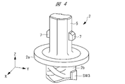
- the handle portion 2 includes a flange portion 2a, a grip portion 2b that is mainly gripped by a user, and a side opposite to the grip portion 2b across the flange portion 2a in the length direction (Z direction) of the grip portion 2b. and a mounting portion 5, which is a protrusion extending to the
- the collar portion 2a is provided between the attached portion 5 and the grip portion 2b. Since the handle 2 is provided with the collar 2a, the user can recognize that the sheath 3 or the blade 4 should be attached to the attached portion 5 at the tip of the collar 2a.
- the length of the mounting part 5 in the Z direction is shorter than the length of the gripping part 2b in the Z direction.
- the length directions of the grip portion 2b and the attached portion 5 are defined as the Z direction
- the two directions along the plane of the collar portion 2a are defined as the X direction and the Y direction.
- the X, Y and Z directions are orthogonal to each other.
- the Y direction is the direction connecting the tip of the Japanese sword and the ridge.
- the blade portion 2 has a recess (not shown) in which the mounting portion 5 is accommodated, and holes are provided at both ends of the blade portion 2 in the Y direction so as to penetrate between the inside of the recess and the outside. It is As shown in FIG. 2, when the blade portion 4 is attached to the handle portion 2, the pressed portion 7 fits into the hole and is exposed in the vicinity of the opening of the hole. By fitting the pressed portion 7 into the hole, the blade portion 4 is fixed to the attached portion 5 .
- the handle 2 has an operation part SW3 on the side surface in the Y direction, and a power supply part SW4 at the end (the head of the Japanese sword) opposite to the mounting part 5 in the X direction.
- the operation part SW3 is, for example, a switch, can be operated by the user, is provided on the outer circumference of the handle part 2, and is provided near the collar part 2a. That is, the handle portion 2 is provided with the operating portion SW3 at a position that can be pressed by the user while holding the handle portion 2 .
- the operation part SW3 is a part operated by the user to output an effect from the effect output part.
- the power supply section SW4 is, for example, a switch, can be operated by the user, is located on the side opposite to the pressed section 7, and is provided near the other end of the handle section 2. Each time the user presses the power supply SW4, the power supply SW4 is switched to an on state (SW4_ON) or an off state (SW4_OFF).
- the effect output unit is, for example, a speaker, is provided inside the handle 2, and is provided to output a plurality of effects.
- the plurality of effects are sounds such as lines or sound effects, for example.
- the handle portion 2 includes a press switch (determination portion) SW1, a press switch (determination portion) SW2, an operation portion SW3, a power supply portion SW4, a pair of pressed portions 7, a control portion ( (not shown) and an effect output unit (not shown) are provided.
- a pair of pressed portions 7 are provided so as to sandwich the attached portion 7 in the Y direction. Further, the pressed portion 7 can be moved so as to be accommodated inside the attached portion 7 in the Y direction by being pressed from the outside. The pressed portion 7 is urged in a direction to move to the outside of the attached portion 7 in the Y direction by, for example, a spring provided inside the attached portion 7 . Therefore, when not pressed from the outside, the pressed portion 7 protrudes outward from the side surface of the attached portion 5 .
- the press switch SW1 is provided in the vicinity of the flange 2a on the mounting portion 5.
- the pressing switch SW1 is formed in the mounting portion 5, and is provided at the end portion of the groove 5c extending in the Z direction and at the end portion on the grip portion 2b side.
- the push switch SW1 is urged to the side opposite to the grip portion 2b in the Z direction (the tip side of the mounting portion 5), and is pushed toward the grip portion 2b when pressed in the Z direction.
- the push switch SW2 is urged outward in the X direction, and when pushed from the outside, moves so as to be pushed inside the mounted part 5 in the X direction.
- FIGS. 3 and 4 show both side surfaces of the mounting part 5 in the X direction.
- the ridgeline (ridge line) of the boundary between the flat ground and the ground of the Japanese sword is Z provided to extend in the direction of
- at least a part of the mounting part 5 has a design that imitates the blade of a sword. Therefore, the user can recognize the wearing part 5 as a part of the blade, and it is possible to improve the user's sense of immersion when playing a swordsman.
- FIG. 5 is a perspective view showing the carp mouth side of the sheath portion 3.
- the sheath 3 includes a recess 6 for accommodating the attached portion 5 when attaching the attached portion 5 to the sheath 3 .
- the state in which the entire attached portion 5 is accommodated in the concave portion 6 and the handle portion 2 is attached to the sheath portion 3 is referred to as a first state.
- Protrusions 8a and 8b that protrude toward the center of the recess 6 (the central axis of the sheath 3) are provided on one side surface of the recess 6 in the X direction.
- the projecting portion 8a is located near the opening of the recess 6, and the projecting portion 8b is located further inside the recess 6 in the Z direction than the projecting portion 8a.
- the projecting portions 8a and 8b are arranged at positions that do not overlap in the Z direction and are spaced apart from each other.
- the simulated sword toy 1 is first in a standby state (step S1).
- the standby state referred to here is the above-described first state, that is, the state in which the mounted portion 5 is completely accommodated in the sheath portion 3 .
- the effect output unit outputs effect 4 (step S11). If the state is not the first state, no operation to the operation unit SW3 is detected. This is because the effect 4 output by the effect output unit in response to the user's operation of the operation unit SW3 is an effect corresponding to the state in which the wearing part 5 is completely accommodated in the sheath part 3. In other words, it is an effect corresponding to a state simulating that the blade is completely housed in the scabbard. To prevent the output of an effect that reduces the interest, since the interest is lowered when the effect is output.
- the simulated sword toy 1 of the present embodiment is designed so that the sheath 3 or the handle 2 will not fly away from the user's hand due to the momentum when the sword is drawn so that the user and the surroundings of the user will not be harmed. , and has a structure in which the sword cannot be drawn by only one action of pulling out the handle 2 in one direction. Specifically, when the wearable part 5 is pulled out from the sheath 3, a part of the wearable part 5 comes into contact with the concave portion 6 of the sheath 3, and the movement of the wearable part 5 is restricted.
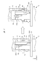
- the mounting portion 5 is moved in the Z direction (lengthwise direction of the sheath) with respect to the sheath 3 and in the direction in which the mounting portion 5 is exposed from the sheath 3 by a predetermined distance L ( FIG. 7) is moved (first movement) to expose a part of the mounting part 5 from the concave part 6, which is called "cutting the Koikuchi".
- a state in which the koikuchi is cut is called a second state.
- the left side shows the sheath 3 and the handle 2 in the first state
- the right side shows the sheath 3 and the handle 2 in the second state.
- the projecting portion 8a described with reference to FIG. 5 is in a state (SW1_ON) pressing the push switch SW1 as shown in FIG.
- the push switch SW1 detects that it is in the first state when it is pushed.
- the projecting portion 8b described with reference to FIG. 5 is in a state (SW2_OFF) in which the push switch SW2 is not pressed as shown in FIG.
- the pressed portion 7 is pushed into and accommodated in the attached portion 5 except for a portion.
- Relatively shallow recesses 6a are provided on both side surfaces in the Y direction in the recess 6 of the sheath 3, and the portion (tip) of the pressed portion 7 is accommodated in the recess 6a.
- On both sides of the recess 6 in the Y direction there are provided a recess 6a and a relatively deep recess 6b so as to be aligned with the recess 6a on the side of the mouthpiece in the Z direction.
- the recessed portion 6a is shallower than the recessed portion 6b and has a smaller volume for accommodating the pressed portion 7. As shown in FIG.
- a protruding portion 6c that protrudes toward the center of the recess 6 is provided between the recess 6a and the recess 6b that are aligned in the Z direction. Therefore, when performing the first movement, it is necessary to pull out the mounted part 5 by applying a force to the extent that the pressed part 7 is further pushed into the mounted part 5 by the pressure from the protruding part 6c. In other words, the concave portion 6 a and the projecting portion 6 c restrict the movement of the attached portion 5 in the Z direction and in the direction in which the attached portion 5 is exposed from the sheath portion 3 .
- the restriction on movement can be released by applying a predetermined force to the handle 2 in the Z direction and in the direction in which the attached part 5 is exposed from the sheath 3 .
- the wearing part 5 is first moved with respect to the sheath part 3, the part to be pressed 7 is taken out from the concave part 6a, and then the sheath part 3 and the wearing part 5 are in the second state. That is, after the first movement, the pressed portion 7 is accommodated in the recess 6b, and the movement in the Z direction of the attached portion 5 in the direction in which the attached portion 5 is further exposed from the sheath portion 3 is the recessed portion 6b. It is regulated by fitting with the pressed portion 7 .
- the projecting portion 8a releases the pressing of the pressing switch SW1.
- the press switch SW1 is turned off (SW1_OFF).
- the control unit detects that the first movement has been made based on the release of the pressure on the push switch SW1.
- the projecting portion 8b presses the press switch SW2.
- the press switch SW2 is turned on (SW2_ON).
- the mounted part 5 has a push switch SW2 that detects that the first movement is made by being pushed, and the protruding part that is a part of the sheath part 3 responds to the first movement. 8b presses the push switch SW2.
- the user cuts the carp by first moving the wearing part 5 with respect to the sheath part 3 (step S3).
- the push switch SW1 is turned off (SW1_OFF) and the push switch SW2 is turned on (SW2_ON).
- the control section in the handle section 2 detects this, and the effect output section outputs the effect 1 (step S4).
- at least a part of the wearing part 5 has a design that imitates the blade of a sword, so that the user cuts the koikuchi to expose a part of the blade, thereby immersing the user in playing a swordsman. you can get a feel.
- the output contents of the effect 1 may be changed depending on whether or not the operation part SW3 is operated in step S2, and by doing so, the interest of the pseudo sword toy 1 is further improved.
- step S5 Since the pressed portion 7 has a slope on the side opposite to the flange portion 2a, it is possible to push the attached portion 5 into the concave portion 6 from the second state to return to the first state, that is, to store the sword. It is possible (step S5). When the sword is retracted, the effect output unit outputs effect 5 (step S12).
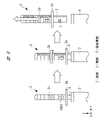
- the axial rotation of the handle 2 is the central axis of the sheath 3 and the handle 2 and the axis extending in the length direction (Z direction) of the sheath 3 and the handle 2.
- the rotation angle is, for example, 20 degrees, and further rotation is restricted. In other words, even if an attempt is made to rotate more than 20 degrees, for example, the surface of the mounting portion 5 abuts against the side surface of the recess 6 and the rotation is restricted.
- the protrusion 8b presses the push switch SW2, so the push switch SW2 is in the ON state (SW2_OFF).
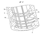
- FIG. 9 shows a perspective view of the sheath portion 3 cut along the Y and Z directions.
- the side surface of the recess 6 shown in FIG. 9 is the surface opposite to the side surface of the recess 6 shown in FIG.
- a plurality of protrusions are formed on the side surface of the recess 6 so as to protrude toward the central axis of the sheath 3 and extend in the circumferential direction of the recess 6 .
- the pressing part 6d which is a protrusion connected to the recess 6b, gradually protrudes in the direction in which the pressed part 7 rotates when the handle 2 is rotated from the second state. height is high.
- the handle portion 2 when the handle portion 2 is axially rotated (displaced) to shift from the second state to the third state, the pressed portion 7 is pressed by the pressing portion 6d in response to this axial rotation, and the portion to be pressed 7 is inserted into the mounted portion 5. be accommodated. Therefore, the locking of the pressed portion 7 in the sheath portion 3 (fitting between the pressed portion 7 and the concave portion 6b) is released, so that the movement of the handle portion 2 in the third state is restricted by the sheath portion 3. can be removed from the sheath 3 without That is, by moving (second movement) the mounting part 5 in the Z direction from the third state in a direction in which the mounting part 5 is further exposed from the sheath 3, the sword is drawn (step S6).
- the handle portion 2 is further moved in the Z direction with respect to the sheath portion 3 from the third state in the direction in which the attached portion 5 is exposed from the sheath portion 3, the second movement is performed.
- the portion 5 can be removed from the sheath portion 3.
- the control unit detects the OFF state (SW1_OFF) of the push switch SW1 and the OFF state (SW2_OFF) of the push switch SW2, and the effect output unit outputs effect 2 (step S4). That is, the control unit detects that the second movement has been performed based on the release of the pressing after the pressing of the push switch SW2.
- the output contents of the effect 2 may be changed depending on whether or not the operation part SW3 is operated in step S2, and by doing so, the interest of the pseudo sword toy 1 is further improved.
- the action of mounting (receiving) the mounting part 5 in the concave part 6 of the sheath part 3, that is, the action of retracting the sword (sword sheathing action) is performed (step S8).
- the inclination of the handle portion 2 with respect to the sheath portion 3 in the axial rotation direction may be an inclination in which the handle portion 2 is not rotated with respect to the sheath portion 3 as in the first state, or may be an inclination such as in the second state.
- the handle portion 2 may be rotated with respect to the sheath portion 3 .
- the receiving portion 5 of the handle 2 that is not attached to the sheath 3 can be inserted into the recess 6 in either the direction of the handle 2 before rotation or the direction of the handle 2 after rotation. shape.
- the protruding portions 8a and 8b pass through the groove 5c shown in FIG. 3 during the sheathing operation of step S8.
- the width of the groove 5c gradually decreases in the Z direction from the tip side of the attached portion 5 toward the grip portion 2b side. Since the opening width of the groove 5c on the tip side of the mounting part 5 is large, the projecting parts 8a and 8b are positioned within the groove 5c regardless of whether the mounting part 5 is oriented before or after the axial rotation. to go into. Slopes 5a and 5b are provided on the surface of the groove 5c at portions where the width of the groove 5c becomes smaller toward the grip portion 2b side.
- the protruding part 8a hits the slope 5a and the trajectory is corrected, and the protruding part 8b hits the slope 5b and corrects the trajectory. can be completely accommodated in the recess 6.
- step S8 the push switch SW2 is turned on (SW2_ON) once from the off state (SW2_OFF), and then turned off again (SW2_OFF). Further, when the mounting portion 5 is completely accommodated in the recess 6, the push switch SW1 is turned on (SW1_ON). As a result, the control unit detects that the sword is sheathed, and the effect output unit outputs effect 3 (step S9).
- the simulated sword toy 1 returns to the standby state, that is, the first state (step 10).
- a simulated sword toy having a handle and a scabbard is used, allowing the user to enjoy the action of drawing the sword, and to improve the interest of the simulated sword toy.
- the handle or sheath may be unintentionally thrown away when the sword is drawn.
- the simulated sword toy of the present embodiment has a structure in which the sword cannot be drawn with only one action of pulling out the handle in one direction, so the safety of the user and the surroundings of the user can be ensured.
- the simulated sword toy 1 has the form of a sword (Japanese sword), but the outer appearance of the sheath 3, the blade 4 and the handle 2 may be other weapon members. It is possible. That is, the simulated sword toy 1 may be in other weapon forms such as, for example, a straight sword, a curved sword, or a double-edged sword.
- the multiple effects included sounds such as lines and sound effects, but the multiple effects may further include other sounds.
- the multiple effects may include light, vibration, or the like.
- the sheath portion 3, blade portion 4, or handle portion 2 may be provided with a light-emitting device or a vibrating device, and these devices may be controlled by the control section.
Landscapes
- Toys (AREA)
Applications Claiming Priority (2)
| Application Number | Priority Date | Filing Date | Title |
|---|---|---|---|
| JP2021031263A JP6947949B1 (ja) | 2021-02-26 | 2021-02-26 | 擬似刀剣玩具 |
| JP2021-031263 | 2021-02-26 |
Publications (1)
| Publication Number | Publication Date |
|---|---|
| WO2022181506A1 true WO2022181506A1 (ja) | 2022-09-01 |
Family
ID=78001299
Family Applications (1)
| Application Number | Title | Priority Date | Filing Date |
|---|---|---|---|
| PCT/JP2022/006795 Ceased WO2022181506A1 (ja) | 2021-02-26 | 2022-02-18 | 擬似刀剣玩具 |
Country Status (3)
| Country | Link |
|---|---|
| JP (3) | JP6947949B1 (https=) |
| CN (2) | CN118045377A (https=) |
| WO (1) | WO2022181506A1 (https=) |
Cited By (1)
| Publication number | Priority date | Publication date | Assignee | Title |
|---|---|---|---|---|
| US20250108281A1 (en) * | 2023-09-29 | 2025-04-03 | Joy Charisse Brutus | Rust blocker |
Families Citing this family (1)
| Publication number | Priority date | Publication date | Assignee | Title |
|---|---|---|---|---|
| JP2024029660A (ja) | 2022-08-22 | 2024-03-06 | コニカミノルタ株式会社 | 画像形成装置 |
Citations (8)
| Publication number | Priority date | Publication date | Assignee | Title |
|---|---|---|---|---|
| JPS4853700U (https=) * | 1971-10-16 | 1973-07-11 | ||
| JPS5347949U (https=) * | 1976-09-24 | 1978-04-22 | ||
| JPS5525065U (https=) * | 1978-08-05 | 1980-02-18 | ||
| JPH1190061A (ja) * | 1997-09-19 | 1999-04-06 | Tabata:Kk | ナイフ保持具 |
| JP2009284992A (ja) * | 2008-05-27 | 2009-12-10 | Bandai Co Ltd | 擬似刀剣玩具 |
| JP2010183991A (ja) * | 2009-02-10 | 2010-08-26 | Bandai Co Ltd | 刀剣玩具 |
| JP2018027251A (ja) * | 2016-08-19 | 2018-02-22 | 株式会社ユアテック | ナイフ装置及び安全装置 |
| JP6899472B1 (ja) * | 2020-06-19 | 2021-07-07 | 株式会社バンダイ | 武器玩具 |
Family Cites Families (16)
| Publication number | Priority date | Publication date | Assignee | Title |
|---|---|---|---|---|
| JPH0471999U (https=) * | 1990-11-02 | 1992-06-25 | ||
| US5947789A (en) * | 1997-07-28 | 1999-09-07 | Thinkway Trading Corporation | Toy sword having a variable color illuminated blade |
| US20010024973A1 (en) * | 1999-12-10 | 2001-09-27 | Christopher Meredith | Laser light sword |
| US20080220693A1 (en) * | 2007-03-07 | 2008-09-11 | Cuisinier Jarret P | Toy sword device and game |
| CN201312995Y (zh) * | 2008-10-22 | 2009-09-23 | 广东奥飞动漫文化股份有限公司 | 趣味性强的玩具剑 |
| JP5391235B2 (ja) * | 2011-06-23 | 2014-01-15 | 京楽産業.株式会社 | 発光遊技具 |
| JP6302174B2 (ja) * | 2013-06-11 | 2018-03-28 | 株式会社アガツマ | 粘土成形玩具 |
| CN106724995A (zh) * | 2015-11-21 | 2017-05-31 | 南京博创工业产品设计有限公司 | 安全刀架 |
| JP6166450B1 (ja) * | 2016-11-29 | 2017-07-19 | 株式会社バンダイ | 演出出力玩具 |
| JP6925480B2 (ja) * | 2017-04-10 | 2021-08-25 | 株式会社バンダイ | 演出出力玩具 |
| CN206959702U (zh) * | 2017-05-27 | 2018-02-02 | 福建省明溪县雪峰宝剑厂 | 一种具有自锁功能且便于拔出的宝剑 |
| CN107485318A (zh) * | 2017-09-06 | 2017-12-19 | 佛山市道道电子科技有限公司 | 一种消毒刀架 |
| CN107764131B (zh) * | 2017-12-01 | 2019-11-22 | 龙泉市沈广隆剑铺 | 一种防滑脱的宝剑 |
| CN107883810A (zh) * | 2017-12-01 | 2018-04-06 | 龙泉市卓越刀剑有限公司 | 一种安全性高的宝剑 |
| CN211410972U (zh) * | 2019-11-29 | 2020-09-04 | 奥飞娱乐股份有限公司 | 剑型拉绳旋转玩具 |
| CN110898441B (zh) * | 2019-11-29 | 2025-12-19 | 奥飞娱乐股份有限公司 | 玩具剑 |
-
2021
- 2021-02-26 JP JP2021031263A patent/JP6947949B1/ja active Active
- 2021-09-16 JP JP2021151612A patent/JP7674974B2/ja active Active
-
2022
- 2022-01-28 CN CN202410266846.3A patent/CN118045377A/zh active Pending
- 2022-01-28 CN CN202210104564.4A patent/CN114470805B/zh active Active
- 2022-02-18 WO PCT/JP2022/006795 patent/WO2022181506A1/ja not_active Ceased
-
2025
- 2025-04-25 JP JP2025073549A patent/JP2025105829A/ja active Pending
Patent Citations (8)
| Publication number | Priority date | Publication date | Assignee | Title |
|---|---|---|---|---|
| JPS4853700U (https=) * | 1971-10-16 | 1973-07-11 | ||
| JPS5347949U (https=) * | 1976-09-24 | 1978-04-22 | ||
| JPS5525065U (https=) * | 1978-08-05 | 1980-02-18 | ||
| JPH1190061A (ja) * | 1997-09-19 | 1999-04-06 | Tabata:Kk | ナイフ保持具 |
| JP2009284992A (ja) * | 2008-05-27 | 2009-12-10 | Bandai Co Ltd | 擬似刀剣玩具 |
| JP2010183991A (ja) * | 2009-02-10 | 2010-08-26 | Bandai Co Ltd | 刀剣玩具 |
| JP2018027251A (ja) * | 2016-08-19 | 2018-02-22 | 株式会社ユアテック | ナイフ装置及び安全装置 |
| JP6899472B1 (ja) * | 2020-06-19 | 2021-07-07 | 株式会社バンダイ | 武器玩具 |
Cited By (1)
| Publication number | Priority date | Publication date | Assignee | Title |
|---|---|---|---|---|
| US20250108281A1 (en) * | 2023-09-29 | 2025-04-03 | Joy Charisse Brutus | Rust blocker |
Also Published As
| Publication number | Publication date |
|---|---|
| JP7674974B2 (ja) | 2025-05-12 |
| CN118045377A (zh) | 2024-05-17 |
| JP2022131973A (ja) | 2022-09-07 |
| CN114470805B (zh) | 2024-03-22 |
| CN114470805A (zh) | 2022-05-13 |
| JP2022132037A (ja) | 2022-09-07 |
| JP2025105829A (ja) | 2025-07-10 |
| JP6947949B1 (ja) | 2021-10-13 |
Similar Documents
| Publication | Publication Date | Title |
|---|---|---|
| JP2025105829A (ja) | 擬似刀剣玩具 | |
| US4170215A (en) | Disk toy and launcher | |
| AU2021307380B2 (en) | Action figure gaming assembly with various attack maneuvers and death configurations | |
| TWI842956B (zh) | 電腦輸入裝置及用於自電腦輸入裝置將球可移除地耦接的方法 | |
| KR20150022267A (ko) | 팽이 발사 장치 | |
| JP7561090B2 (ja) | 武器玩具 | |
| JP2025035365A (ja) | 模型玩具、及び装飾部品 | |
| US20090205761A1 (en) | Ergonomic Stylus Jacket | |
| JPH0680494U (ja) | 武器玩具 | |
| JP2006158786A (ja) | パチンコ機の発射操作装置 | |
| CN221808349U (zh) | 组合陀螺和陀螺套装 | |
| JP2022094476A (ja) | 釣竿用のリールシート | |
| KR101892367B1 (ko) | 볼 요요 | |
| CA3185902C (en) | Action figure gaming assembly with various attack maneuvers and death configurations | |
| CN217645831U (zh) | 陀螺发射器 | |
| JP4491493B2 (ja) | パチンコ遊技機の打球発射ハンドル | |
| JP2005261579A (ja) | ぬいぐるみ | |
| JP4445885B2 (ja) | パチンコ遊技機の打球発射ハンドル | |
| JP4751672B2 (ja) | 変形装飾構造を備えた玩具 | |
| JPH09313740A (ja) | 人形駆動装置 | |
| JP6180584B2 (ja) | 彫刻刀 | |
| JP2010273822A (ja) | 刀剣玩具 | |
| JP2013091304A5 (https=) | ||
| JP2007117468A (ja) | ゴルフ練習用グリップ保持具 | |
| JP2007135817A (ja) | 球体発射玩具 |
Legal Events
| Date | Code | Title | Description |
|---|---|---|---|
| 121 | Ep: the epo has been informed by wipo that ep was designated in this application |
Ref document number: 22759542 Country of ref document: EP Kind code of ref document: A1 |
|
| NENP | Non-entry into the national phase |
Ref country code: DE |
|
| 122 | Ep: pct application non-entry in european phase |
Ref document number: 22759542 Country of ref document: EP Kind code of ref document: A1 |