WO2022180718A1 - 冷凍サイクル装置 - Google Patents
冷凍サイクル装置 Download PDFInfo
- Publication number
- WO2022180718A1 WO2022180718A1 PCT/JP2021/006991 JP2021006991W WO2022180718A1 WO 2022180718 A1 WO2022180718 A1 WO 2022180718A1 JP 2021006991 W JP2021006991 W JP 2021006991W WO 2022180718 A1 WO2022180718 A1 WO 2022180718A1
- Authority
- WO
- WIPO (PCT)
- Prior art keywords
- refrigerant
- valve
- refrigeration cycle
- defrosting
- receiver
- Prior art date
- Legal status (The legal status is an assumption and is not a legal conclusion. Google has not performed a legal analysis and makes no representation as to the accuracy of the status listed.)
- Ceased
Links
Images



Classifications
-
- F—MECHANICAL ENGINEERING; LIGHTING; HEATING; WEAPONS; BLASTING
- F25—REFRIGERATION OR COOLING; COMBINED HEATING AND REFRIGERATION SYSTEMS; HEAT PUMP SYSTEMS; MANUFACTURE OR STORAGE OF ICE; LIQUEFACTION SOLIDIFICATION OF GASES
- F25B—REFRIGERATION MACHINES, PLANTS OR SYSTEMS; COMBINED HEATING AND REFRIGERATION SYSTEMS; HEAT PUMP SYSTEMS
- F25B49/00—Arrangement or mounting of control or safety devices
- F25B49/02—Arrangement or mounting of control or safety devices for compression type machines, plants or systems
-
- F—MECHANICAL ENGINEERING; LIGHTING; HEATING; WEAPONS; BLASTING
- F25—REFRIGERATION OR COOLING; COMBINED HEATING AND REFRIGERATION SYSTEMS; HEAT PUMP SYSTEMS; MANUFACTURE OR STORAGE OF ICE; LIQUEFACTION SOLIDIFICATION OF GASES
- F25B—REFRIGERATION MACHINES, PLANTS OR SYSTEMS; COMBINED HEATING AND REFRIGERATION SYSTEMS; HEAT PUMP SYSTEMS
- F25B47/00—Arrangements for preventing or removing deposits or corrosion, not provided for in another subclass
- F25B47/02—Defrosting cycles
-
- F—MECHANICAL ENGINEERING; LIGHTING; HEATING; WEAPONS; BLASTING
- F25—REFRIGERATION OR COOLING; COMBINED HEATING AND REFRIGERATION SYSTEMS; HEAT PUMP SYSTEMS; MANUFACTURE OR STORAGE OF ICE; LIQUEFACTION SOLIDIFICATION OF GASES
- F25B—REFRIGERATION MACHINES, PLANTS OR SYSTEMS; COMBINED HEATING AND REFRIGERATION SYSTEMS; HEAT PUMP SYSTEMS
- F25B47/00—Arrangements for preventing or removing deposits or corrosion, not provided for in another subclass
- F25B47/02—Defrosting cycles
- F25B47/022—Defrosting cycles hot gas defrosting
-
- F—MECHANICAL ENGINEERING; LIGHTING; HEATING; WEAPONS; BLASTING
- F25—REFRIGERATION OR COOLING; COMBINED HEATING AND REFRIGERATION SYSTEMS; HEAT PUMP SYSTEMS; MANUFACTURE OR STORAGE OF ICE; LIQUEFACTION SOLIDIFICATION OF GASES
- F25B—REFRIGERATION MACHINES, PLANTS OR SYSTEMS; COMBINED HEATING AND REFRIGERATION SYSTEMS; HEAT PUMP SYSTEMS
- F25B2400/00—Component parts or details not otherwise provided for in this subclass
- F25B2400/19—Pumping down refrigerant from one part of the cycle to another part of the cycle, e.g. when the cycle is changed from cooling to heating, or before a defrost cycle is started
-
- F—MECHANICAL ENGINEERING; LIGHTING; HEATING; WEAPONS; BLASTING
- F25—REFRIGERATION OR COOLING; COMBINED HEATING AND REFRIGERATION SYSTEMS; HEAT PUMP SYSTEMS; MANUFACTURE OR STORAGE OF ICE; LIQUEFACTION SOLIDIFICATION OF GASES
- F25B—REFRIGERATION MACHINES, PLANTS OR SYSTEMS; COMBINED HEATING AND REFRIGERATION SYSTEMS; HEAT PUMP SYSTEMS
- F25B2600/00—Control issues
- F25B2600/11—Fan speed control
- F25B2600/111—Fan speed control of condenser fans
-
- F—MECHANICAL ENGINEERING; LIGHTING; HEATING; WEAPONS; BLASTING
- F25—REFRIGERATION OR COOLING; COMBINED HEATING AND REFRIGERATION SYSTEMS; HEAT PUMP SYSTEMS; MANUFACTURE OR STORAGE OF ICE; LIQUEFACTION SOLIDIFICATION OF GASES
- F25B—REFRIGERATION MACHINES, PLANTS OR SYSTEMS; COMBINED HEATING AND REFRIGERATION SYSTEMS; HEAT PUMP SYSTEMS
- F25B2600/00—Control issues
- F25B2600/11—Fan speed control
- F25B2600/112—Fan speed control of evaporator fans
-
- F—MECHANICAL ENGINEERING; LIGHTING; HEATING; WEAPONS; BLASTING
- F25—REFRIGERATION OR COOLING; COMBINED HEATING AND REFRIGERATION SYSTEMS; HEAT PUMP SYSTEMS; MANUFACTURE OR STORAGE OF ICE; LIQUEFACTION SOLIDIFICATION OF GASES
- F25B—REFRIGERATION MACHINES, PLANTS OR SYSTEMS; COMBINED HEATING AND REFRIGERATION SYSTEMS; HEAT PUMP SYSTEMS
- F25B2600/00—Control issues
- F25B2600/25—Control of valves
- F25B2600/2501—Bypass valves
-
- F—MECHANICAL ENGINEERING; LIGHTING; HEATING; WEAPONS; BLASTING
- F25—REFRIGERATION OR COOLING; COMBINED HEATING AND REFRIGERATION SYSTEMS; HEAT PUMP SYSTEMS; MANUFACTURE OR STORAGE OF ICE; LIQUEFACTION SOLIDIFICATION OF GASES
- F25B—REFRIGERATION MACHINES, PLANTS OR SYSTEMS; COMBINED HEATING AND REFRIGERATION SYSTEMS; HEAT PUMP SYSTEMS
- F25B2600/00—Control issues
- F25B2600/25—Control of valves
- F25B2600/2513—Expansion valves
-
- F—MECHANICAL ENGINEERING; LIGHTING; HEATING; WEAPONS; BLASTING
- F25—REFRIGERATION OR COOLING; COMBINED HEATING AND REFRIGERATION SYSTEMS; HEAT PUMP SYSTEMS; MANUFACTURE OR STORAGE OF ICE; LIQUEFACTION SOLIDIFICATION OF GASES
- F25B—REFRIGERATION MACHINES, PLANTS OR SYSTEMS; COMBINED HEATING AND REFRIGERATION SYSTEMS; HEAT PUMP SYSTEMS
- F25B2600/00—Control issues
- F25B2600/25—Control of valves
- F25B2600/2523—Receiver valves
-
- F—MECHANICAL ENGINEERING; LIGHTING; HEATING; WEAPONS; BLASTING
- F25—REFRIGERATION OR COOLING; COMBINED HEATING AND REFRIGERATION SYSTEMS; HEAT PUMP SYSTEMS; MANUFACTURE OR STORAGE OF ICE; LIQUEFACTION SOLIDIFICATION OF GASES
- F25B—REFRIGERATION MACHINES, PLANTS OR SYSTEMS; COMBINED HEATING AND REFRIGERATION SYSTEMS; HEAT PUMP SYSTEMS
- F25B2700/00—Sensing or detecting of parameters; Sensors therefor
- F25B2700/19—Pressures
- F25B2700/193—Pressures of the compressor
- F25B2700/1931—Discharge pressures
-
- F—MECHANICAL ENGINEERING; LIGHTING; HEATING; WEAPONS; BLASTING
- F25—REFRIGERATION OR COOLING; COMBINED HEATING AND REFRIGERATION SYSTEMS; HEAT PUMP SYSTEMS; MANUFACTURE OR STORAGE OF ICE; LIQUEFACTION SOLIDIFICATION OF GASES
- F25B—REFRIGERATION MACHINES, PLANTS OR SYSTEMS; COMBINED HEATING AND REFRIGERATION SYSTEMS; HEAT PUMP SYSTEMS
- F25B2700/00—Sensing or detecting of parameters; Sensors therefor
- F25B2700/21—Temperatures
- F25B2700/2104—Temperatures of an indoor room or compartment
-
- F—MECHANICAL ENGINEERING; LIGHTING; HEATING; WEAPONS; BLASTING
- F25—REFRIGERATION OR COOLING; COMBINED HEATING AND REFRIGERATION SYSTEMS; HEAT PUMP SYSTEMS; MANUFACTURE OR STORAGE OF ICE; LIQUEFACTION SOLIDIFICATION OF GASES
- F25B—REFRIGERATION MACHINES, PLANTS OR SYSTEMS; COMBINED HEATING AND REFRIGERATION SYSTEMS; HEAT PUMP SYSTEMS
- F25B2700/00—Sensing or detecting of parameters; Sensors therefor
- F25B2700/21—Temperatures
- F25B2700/2117—Temperatures of an evaporator
- F25B2700/21171—Temperatures of an evaporator of the fluid cooled by the evaporator
- F25B2700/21173—Temperatures of an evaporator of the fluid cooled by the evaporator at the outlet
Definitions
- the disclosure in this specification relates to a refrigeration cycle device that cools indoor air.
- the present invention relates to a refrigeration cycle device that performs a defrosting operation to remove frost adhering to an evaporator.
- a refrigeration cycle apparatus performs defrosting operation intermittently because frost adheres to an evaporator when an operation is performed to cool the inside of a freezer warehouse, which is a cooling target, to 0° C. or less.
- Defrosting methods include heating the evaporator with an electric heater and circulating high-temperature refrigerant through the evaporator.
- the precooling operation is continued until the evaporator outlet reaches a predetermined temperature or the predetermined time elapses. Liquid refrigerant may return to the accumulator.
- the present invention has been made to solve the above-described problems, and provides a highly reliable refrigeration cycle apparatus by avoiding the liquid return phenomenon just before the end of the precooling operation.
- one of the disclosed refrigeration cycle devices is a refrigerant circuit in which a compressor, a condenser, a receiver, an expansion valve, and an evaporator are sequentially connected and refrigerant is enclosed; defrosting means for melting frost adhering to the evaporator; and a control means for selecting one of cooling operation, defrosting operation, and precooling operation, In the pre-cooling operation, a predetermined amount of refrigerant is held in the receiver so that the amount of refrigerant circulating in the refrigerant circuit is smaller than in the cooling operation and the defrosting operation.
- the refrigeration cycle apparatus holds a predetermined amount of liquid refrigerant inside the receiver during precooling operation, and precooling operation is performed with a smaller amount of refrigerant than usual, so precooling operation is performed until the evaporator is sufficiently cooled. Even with this, liquid returns to the accumulator is small, and a highly reliable refrigeration cycle apparatus can be obtained.
- FIG. 1 is a refrigerant circuit configuration diagram of an example of a refrigeration cycle apparatus according to Embodiment 1.
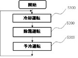
- FIG. 4 is a flowchart showing basic operations of operation control of the refrigeration cycle apparatus according to Embodiment 1; 4 is a flowchart showing control operations during cooling operation of the refrigeration cycle apparatus according to Embodiment 1.
- FIG. 4 is a flow chart showing the control operation of the defrosting operation of the refrigeration cycle apparatus according to Embodiment 1.
- FIG. 1 is a refrigerant circuit configuration diagram of a refrigeration cycle device that performs hot gas defrosting according to Embodiment 1.
- FIG. 4 is a flow chart showing a control operation during precooling operation of the refrigeration cycle apparatus according to Embodiment 1; FIG.
- FIG. 6 is a refrigerant circuit configuration diagram showing an example of a refrigeration cycle apparatus according to Embodiment 2;
- FIG. 11 is a refrigerant circuit configuration diagram showing an example of a refrigeration cycle apparatus according to Embodiment 3;
- FIG. 11 is a refrigerant circuit configuration diagram showing an example of a refrigeration cycle apparatus according to Embodiment 4;
- FIG. 1 is a refrigerant circuit configuration diagram showing an example of a refrigeration cycle apparatus according to Embodiment 1 of the present disclosure.
- the refrigeration cycle apparatus 100 has an outdoor unit 1 and an indoor unit 2 connected by a liquid pipe 3 and a gas pipe 4 to form one refrigerant circuit.
- This refrigerant circuit contains R407C, which is a mixed refrigerant of three types of HFC refrigerants with different boiling points.
- the refrigerant to be enclosed is not limited to this, and may be, for example, a mixed refrigerant of R1234yf, which is an HFO refrigerant, and R32.
- a mixed refrigerant containing a HC refrigerant such as R290 or a natural refrigerant such as CO2 as one component may be employed.
- the outdoor unit 1 connects a compressor 5 to which an accumulator 13 is connected on the suction side, an outdoor heat exchanger 6, a receiver 8, a first on-off valve 14, and an inlet of the receiver 8 and an outlet of the first on-off valve 14. , a bypass 16 with a second on-off valve 15 .
- the outdoor blower 7 provided in association with the outdoor heat exchanger 6 adjusts the amount of heat exchanged between the refrigerant and the outdoor air by changing the amount of air blown to the outdoor heat exchanger 6 .
- the receiver 8 has a function of storing surplus refrigerant in the refrigerant sealed in the refrigerant circuit.
- a pressure sensor 21 is installed between the compressor 5 and the accumulator 13 to detect a low pressure Ps during refrigeration cycle operation.
- the indoor unit 2 is installed, for example, in a refrigerated warehouse where the indoor air temperature is adjusted to around -5°C.
- the indoor unit 2 incorporates a refrigerant circuit in which a liquid solenoid valve 9, an expansion valve 10, and an indoor heat exchanger 11 are sequentially connected.
- the indoor fan 12 is arranged in association with the indoor heat exchanger 11 and adjusts the amount of heat exchanged between the refrigerant and the indoor air.
- the expansion valve 10 is, for example, a thermostatic expansion valve, and its opening is adjusted so that the refrigerant at the outlet of the indoor heat exchanger 11 has a predetermined degree of superheat.
- the indoor heat exchanger 11 also includes a temperature sensor 22 for detecting the representative temperature Teva and a temperature sensor 23 for detecting the indoor air temperature Ta on the refrigerant outlet side.
- the refrigeration cycle apparatus 100 includes a control device 30 that grasps the operating states of the outdoor unit 1 and the indoor unit 2 and controls actuators.
- the control device 30 starts/stops the compressor 5 and the outdoor fan 7 and opens/closes the first opening/closing valve 14 and the second opening/closing valve 15 .
- the indoor blower 12 is started/stopped, the liquid electromagnetic valve 9 is opened/closed, and the electric heater 24 is energized/cut off.
- This control device 30 may be built in the outdoor unit 1 or the indoor unit 2, or may be arranged in the living space where the user resides.
- the controller 30 also has a user interface that allows the user to set the indoor target temperature Tset.
- FIG. 2 is a flow chart showing the basic operations of the operation control of the refrigeration cycle apparatus 100 shown in Embodiment 1.
- FIG. When the operation of the refrigeration cycle apparatus 100 is started, first, in step S100, the refrigeration cycle apparatus 100 performs a cooling operation in which the indoor air is maintained at the indoor target temperature Tset set by the user. If the defrosting start condition is satisfied during the cooling operation, the process proceeds to step S200.
- step S ⁇ b>200 the refrigerating cycle device 100 performs a defrosting operation to remove frost adhering to the indoor heat exchanger 11 . If the defrosting operation end condition is satisfied during the defrosting operation, the process proceeds to step S300.
- step S300 the refrigerating cycle apparatus 100 performs a pre-cooling operation for cooling the indoor heat exchanger 11, which has reached a high temperature due to the defrosting operation, to a predetermined temperature. After completing the precooling operation, the refrigeration cycle apparatus 100 returns to step S100 and repeats the operation of restarting the cooling operation. Subsequently, a series of these control operations will be described in further detail.
- FIG. 3 is a flow chart showing the control operation during the cooling operation of the refrigeration cycle apparatus 100 shown in Embodiment 1.
- the control device 30 of the refrigeration cycle apparatus 100 configures a cooling circuit that opens the liquid electromagnetic valve 9 and the first on-off valve 14 and closes the second on-off valve 15 in step S101.
- Compressor 5 and indoor fan 12 are started.
- the description is omitted assuming that the operation is always interlocked with the compressor 5.
- step S101 in the outdoor unit 1, the high-temperature and high-pressure gas refrigerant discharged from the compressor 5 releases heat to the outdoor air in the outdoor heat exchanger 7, condenses and liquefies, and passes through the receiver 8 and the first on-off valve 14. and flows into the liquid tube 3. At this time, the excess liquid refrigerant is stored in the receiver 8 .
- the refrigerant that has flowed into the indoor unit 2 from the liquid pipe 3 passes through the liquid solenoid valve 9 , is decompressed by the expansion valve 10 , and enters the indoor heat exchanger 11 in a low-pressure two-phase state.
- the low-pressure two-phase refrigerant that has flowed into the indoor heat exchanger 11 evaporates while exchanging heat with the indoor air sucked by the indoor fan 12 to become a gas refrigerant.
- the refrigerant gasified in the indoor unit 2 returns to the outdoor unit 1 via the gas pipe 4 .
- the refrigerant returned to the outdoor unit 1 passes through the accumulator 13 and is sucked into the compressor 5 again.
- the indoor air is sucked into the indoor unit 2 by the indoor blower 12 and is cooled to a low temperature by heat exchange with the indoor heat exchanger 11 and circulates in the room. In this way, the cooling operation that keeps the room at the predetermined temperature is continued.
- Step S102 is a control step for determining whether the defrosting operation is necessary.
- the control device 30 terminates the cooling operation and shifts to the defrosting operation.
- step S102 for example, it may be determined that the defrosting condition is satisfied by detecting that the cooling operation has been continued for a predetermined time set in advance by a timer. Alternatively, determination may be made based on the occurrence of a temperature difference of 15° C. or more between the indoor air temperature Ta and the saturation temperature of the low pressure Ps.
- step S103 In a state in which the cooling operation is continued without satisfying the defrosting conditions, the control device 30 monitors in step S103 to prevent the indoor air temperature from dropping too much.
- step S103 for example, when the indoor air temperature Ta becomes lower than the indoor target temperature Tset by 5° C. or more, the process shifts to the thermo-off operation starting from step S104.
- the controller 30 first closes the liquid electromagnetic valve 9 in step S104 to perform the refrigerant recovery operation.
- the liquid solenoid valve 9 is closed, the refrigerant is no longer supplied to the indoor unit 2 from the liquid pipe 3, so the refrigerant existing in the indoor unit 2 and the gas pipe 4 is recovered to the outdoor unit 1 side.
- the low pressure Ps of the refrigeration cycle detected by the pressure sensor 22 gradually decreases.
- the control device 30 determines that the refrigerant recovery is completed when the low pressure Ps has decreased to, for example, the atmospheric pressure or less in step S105 for determining whether to stop the compressor, and stops the compressor 5 in step S106.
- the refrigerant recovery operation is completed when the compressor 5 is stopped.
- step S106 When the refrigerant recovery operation is completed in step S106, the indoor unit 2 will no longer cool the indoor air, so the indoor air temperature Ta will gradually rise.
- the control device 30 monitors whether the indoor air temperature Ta becomes higher than the indoor target temperature Tset in step S107. In step S107, for example, when the indoor air temperature Ta becomes equal to or higher than the indoor target temperature Tset, the thermo-off operation is terminated, and the process returns to step S101 to start the cooling operation.
- the indoor air temperature Ta is adjusted within a range from the indoor target temperature Tset to Tset-5°C.
- the control of the defrosting operation which is the control operation after the cooling operation ends, will be described.
- FIG. 4 is a flow chart showing the control operation of the defrosting operation of the refrigeration cycle apparatus 100 shown in the first embodiment.
- the control device 30 determines that the defrosting condition is satisfied in step S102 during the cooling operation, it ends the cooling operation and shifts to the defrosting operation. At this point, the control device 30 assumes that a predetermined amount of frost has adhered to the indoor air intake side of the indoor heat exchanger 11 .
- the controller 30 When the defrosting operation is started, the controller 30 first closes the liquid solenoid valve 9 in step S201, and then continues this operation until the low pressure Ps becomes equal to or lower than the atmospheric pressure in step S202.
- This control operation is the same as the refrigerant recovery operation described in steps S104 and S105 of the cooling operation control in FIG.
- the control device 30 confirms that the low pressure Ps has become equal to or lower than the atmospheric pressure in step S202, the control device 30 proceeds to step S203, stops the compressor 5 and the indoor fan 12, and energizes the electric heater 24.
- the representative temperature Teva of the indoor heat exchanger 11 detected by the temperature sensor 22 begins to rise as the frost progresses.
- the control device 30 monitors whether the defrosting is completed in step S204. Completion of defrosting is determined by determining that there is no unmelted frost in the indoor heat exchanger 11 . For example, when the representative temperature Teva detected by the temperature sensor 22 reaches 30° C. or higher, the process proceeds to step 205 and energization of the electric heater 24 is terminated. With this control operation, the defrosting operation is completed, and the controller 30 shifts to the precooling operation.
- FIGS. 1 to 4 show an example of the defrosting operation by the electric heater 24, but the defrosting method is not limited to this.
- a defrosting operation may be performed with a high-temperature gas refrigerant.
- FIG. 5 is a refrigerant circuit configuration diagram of a refrigeration cycle device that performs hot gas defrosting.
- the outdoor unit 1 has a hot gas branch pipe 41 branched from the compressor outlet, and the hot gas branch pipe 41 is connected to a hot gas pipe 43 via a hot gas valve 42 that can be opened and closed.
- the hot gas pipe 43 is a third connection pipe that connects the outdoor unit 1 and the indoor unit 2, and in the indoor unit 2, is connected to a branch pipe from between the expansion valve 10 and the indoor heat exchanger 11. there is
- the liquid solenoid valve 9 is closed and the hot gas valve 42 is opened after the cooling operation is completed.
- the hot gas valve 42 is opened, the high-temperature gas refrigerant discharged from the compressor 5 flows through the hot gas pipe 43 into the indoor unit 2 to heat the indoor heat exchanger 11 .
- This hot gas defrosting operation is continued until the representative temperature Teva of the indoor heat exchanger 11 detected by the temperature sensor 22 reaches 30° C., and then the defrosting operation is terminated, similarly to the heater defrosting operation described above.
- the hot gas defrosting operation is terminated by closing the hot gas valve 42 .
- FIG. 6 is a flow chart showing the control operation during the precooling operation of the refrigeration cycle apparatus 100 shown in Embodiment 1.
- the controller 30 switches the refrigerant circuit of the refrigeration cycle device 100 to the pre-cooling circuit in step S301.
- Table 1 is a table showing control states of actuator groups in each of the cooling circuit, defrosting circuit, and pre-cooling circuit of the refrigeration cycle apparatus 100 .
- the controller 30 opens the liquid electromagnetic valve 9 and the second on-off valve 15, closes the first on-off valve 14, and starts the compressor 5.
- the refrigerant amount distribution in the refrigerant circuit before being set to the pre-cooling circuit remains in the state where the refrigerant recovery operation was performed during the defrosting operation, most of the enclosed refrigerant is in the receiver 8 and the liquid pipe 3. It exists as a liquid refrigerant.
- the pre-cooling circuit is set in such a state, the liquid refrigerant stored in the receiver 8 is no longer discharged from the receiver 8 .
- the control device starts up the compressor 5 in step S302, but the amount of refrigerant forming the refrigerating cycle is very small. Therefore, the high-temperature refrigerant discharged from the compressor 5 radiates heat to the outside air in the outdoor heat exchanger 6, but flows out of the outdoor heat exchanger 6 without being completely liquefied.
- This two-phase refrigerant containing a small amount of liquid refrigerant passes through the second on-off valve 15 and flows into the liquid pipe 3 and the indoor unit 2 without flowing into the receiver 8 .
- the high-pressure two-phase refrigerant that has flowed into the indoor unit 2 is decompressed by the liquid solenoid valve 9 and the expansion valve 10 and flows into the indoor heat exchanger 11 . Since the indoor heat exchanger 11 is at a high temperature of 30° C. or higher at the start of the precooling operation, that is, at the end of the defrosting operation, it is cooled by the inflow of the refrigerant and gradually becomes low. At this time, since the indoor blower 12 is stopped, the refrigerant does not absorb heat from the indoor air, but only from the indoor heat exchanger 11 and evaporates.
- the control device 30 determines to end the precooling operation in step S303.
- the precooling operation ends when the representative temperature Teva of the indoor heat exchanger 11 falls below 0°C.
- the indoor heat exchanger 11 is at a low temperature while the outdoor fan 12 is stopped, so the refrigerant containing a small amount of liquid refrigerant flows out of the indoor heat exchanger 11 without being able to evaporate.
- the pre-cooling operation is performed with the same amount of refrigerant as the cooling operation as in the conventional case, a large amount of liquid refrigerant that cannot be evaporated accumulates in the accumulator 13 .
- the pre-cooling operation is performed with a large amount of refrigerant stored in the receiver 8 , so the refrigerant does not accumulate in the accumulator 13 . Due to this action, when the cooling operation is restarted after the pre-cooling operation ends, the cooling operation can be performed quickly without causing a shortage of refrigerant.
- the precooling operation can be continued until the temperature of the indoor heat exchanger 11 reaches a sufficiently low temperature. Due to this action, high-temperature air is not blown into the room at the start of the cooling operation, and it is possible to avoid thermal damage to articles stored at a low temperature in the room.
- the reliability of the refrigeration cycle apparatus can be improved and the accumulator 13 can be miniaturized.
- the indoor heat exchanger 11 Since the indoor heat exchanger 11 is sufficiently cooled by the pre-cooling operation, high-temperature air is not supplied indoors during the subsequent cooling operation, and a high-quality freezer compartment can be provided.
- the defrosting operation can sufficiently heat until the frost is completely melted, the indoor heat exchanger 11 is deformed or clogged due to the growth of frost and water droplets that could not be removed by the defrosting operation. It is possible to provide a highly reliable refrigeration cycle apparatus that does not cause any problems.
- FIG. 7 is a refrigerant circuit configuration diagram showing the configuration of a refrigeration cycle apparatus according to Embodiment 2. As shown in FIG. 7 the receiver 8 is provided with a second outlet 40 above, in addition to the normal outlet located below. A pipe extending from the second outlet 40 merges with the outlet of the first on-off valve 14 via the second on-off valve 15 .
- the piping extending from the second outlet 40 has the function of adjusting the amount of refrigerant during the precooling operation described above.
- the amount of refrigerant during the precooling operation may become excessive. be.
- the refrigerating cycle device 102 after the precooling operation is started, heat is radiated in the indoor heat exchanger 6 , and the two-phase refrigerant containing the liquid refrigerant once flows into the receiver 8 .
- the two-phase refrigerant that has flowed into the receiver 8 is separated into gas and liquid inside the receiver 8 , and only the gas refrigerant flows out from the second outlet 40 , while the separated liquid refrigerant remains inside the receiver 8 . That is, the refrigerant existing outside the receiver 8 at the start of the precooling operation is stored in the receiver 8 during the precooling operation.
- Embodiment 2 of the present disclosure it is possible to reduce the amount of effective refrigerant circulating during the precooling operation compared to when the precooling operation is started. As a result, the amount of liquid returned during the precooling operation is further reduced, and the reliability of the refrigeration cycle device 102 can be improved.
- FIG. 8 is a refrigerant circuit configuration diagram showing the configuration of a refrigeration cycle apparatus according to Embodiment 3.
- the refrigeration cycle device 103 is provided with a check valve 51 at the inlet of the receiver 8 .
- the check valve 51 has a function of preventing the refrigerant from flowing out of the receiver 8 even when the condensation pressure in the refrigeration cycle becomes lower than the pressure inside the receiver 8 during the precooling operation. This function completely isolates the refrigerant stored in the receiver 8 from the refrigerant circuit when the first on-off valve 14 is closed by setting the pre-cooling circuit.
- the refrigerant does not flow out from the receiver 8 during the precooling operation.
- a pre-cooling operation can be performed.
- FIG. 9 is a refrigerant circuit configuration diagram showing the configuration of a refrigeration cycle apparatus according to Embodiment 4. As shown in FIG. A three-way switching valve 52 is arranged in the refrigerating cycle device 104 as a substitute for the first on-off valve 14 and the second on-off valve 15 of the refrigerating cycle device 103 of Embodiment 3 shown in FIG.
- the refrigeration cycle devices 100, 102, and 103 open the first on-off valve and close the second on-off valve during cooling operation and defrosting operation.
- the first on-off valve is closed and the second on-off valve is opened. That is, one of the first on-off valve 14 and the second on-off valve 15 is always opened and the other is closed.
- the refrigerating cycle device 104 replaces the two on-off valves with one three-way switching valve 52, the refrigerant circuit can be changed to the pre-cooling circuit or the cooling circuit with one switching signal. Accordingly, one terminal and one signal line for the circuit switching signal on the control board are sufficient.
- the configuration shown in the above embodiment shows an example of the content of the present disclosure, and can be combined with another known technique, and the configuration can be configured without departing from the gist of the present disclosure. It is also possible to omit or change part of
Landscapes
- Engineering & Computer Science (AREA)
- Physics & Mathematics (AREA)
- Mechanical Engineering (AREA)
- Thermal Sciences (AREA)
- General Engineering & Computer Science (AREA)
- Defrosting Systems (AREA)
Priority Applications (4)
| Application Number | Priority Date | Filing Date | Title |
|---|---|---|---|
| PCT/JP2021/006991 WO2022180718A1 (ja) | 2021-02-25 | 2021-02-25 | 冷凍サイクル装置 |
| CN202180093778.XA CN116917674A (zh) | 2021-02-25 | 2021-02-25 | 制冷循环装置 |
| EP21927820.7A EP4300004A4 (en) | 2021-02-25 | 2021-02-25 | REFRIGERATION CYCLE DEVICE |
| JP2023501744A JP7387054B2 (ja) | 2021-02-25 | 2021-02-25 | 冷凍サイクル装置 |
Applications Claiming Priority (1)
| Application Number | Priority Date | Filing Date | Title |
|---|---|---|---|
| PCT/JP2021/006991 WO2022180718A1 (ja) | 2021-02-25 | 2021-02-25 | 冷凍サイクル装置 |
Publications (1)
| Publication Number | Publication Date |
|---|---|
| WO2022180718A1 true WO2022180718A1 (ja) | 2022-09-01 |
Family
ID=83047856
Family Applications (1)
| Application Number | Title | Priority Date | Filing Date |
|---|---|---|---|
| PCT/JP2021/006991 Ceased WO2022180718A1 (ja) | 2021-02-25 | 2021-02-25 | 冷凍サイクル装置 |
Country Status (4)
| Country | Link |
|---|---|
| EP (1) | EP4300004A4 (https=) |
| JP (1) | JP7387054B2 (https=) |
| CN (1) | CN116917674A (https=) |
| WO (1) | WO2022180718A1 (https=) |
Cited By (3)
| Publication number | Priority date | Publication date | Assignee | Title |
|---|---|---|---|---|
| CN115930530A (zh) * | 2022-12-05 | 2023-04-07 | 珠海格力电器股份有限公司 | 一种冰箱化霜控制方法及电路 |
| WO2025243501A1 (ja) * | 2024-05-24 | 2025-11-27 | 日立ジョンソンコントロールズ空調株式会社 | 冷凍サイクル装置 |
| WO2025243502A1 (ja) * | 2024-05-24 | 2025-11-27 | 日立ジョンソンコントロールズ空調株式会社 | 冷凍サイクル装置 |
Citations (3)
| Publication number | Priority date | Publication date | Assignee | Title |
|---|---|---|---|---|
| JPH0663692B2 (ja) * | 1986-09-08 | 1994-08-22 | 三洋電機株式会社 | 低温ショーケース |
| JP2014119145A (ja) * | 2012-12-14 | 2014-06-30 | Sharp Corp | 空気調和機 |
| JP2017166730A (ja) | 2016-03-15 | 2017-09-21 | 株式会社デンソー | 冷凍装置 |
Family Cites Families (6)
| Publication number | Priority date | Publication date | Assignee | Title |
|---|---|---|---|---|
| US3392542A (en) * | 1966-10-14 | 1968-07-16 | Larkin Coils Inc | Hot gas defrostable refrigeration system |
| US5937660A (en) * | 1993-07-26 | 1999-08-17 | Lau; Billy Ying Bui | Quick cooling air conditioning system |
| US6286322B1 (en) * | 1998-07-31 | 2001-09-11 | Ardco, Inc. | Hot gas defrost refrigeration system |
| JP4326274B2 (ja) * | 2003-06-30 | 2009-09-02 | ホシザキ電機株式会社 | 冷凍回路 |
| JP2009287789A (ja) * | 2008-05-27 | 2009-12-10 | Daikin Ind Ltd | 冷凍装置 |
| KR101918224B1 (ko) * | 2012-01-31 | 2018-11-13 | 엘지전자 주식회사 | 냉장고 및 그 제상 운전 방법 |
-
2021
- 2021-02-25 WO PCT/JP2021/006991 patent/WO2022180718A1/ja not_active Ceased
- 2021-02-25 EP EP21927820.7A patent/EP4300004A4/en not_active Withdrawn
- 2021-02-25 JP JP2023501744A patent/JP7387054B2/ja active Active
- 2021-02-25 CN CN202180093778.XA patent/CN116917674A/zh active Pending
Patent Citations (3)
| Publication number | Priority date | Publication date | Assignee | Title |
|---|---|---|---|---|
| JPH0663692B2 (ja) * | 1986-09-08 | 1994-08-22 | 三洋電機株式会社 | 低温ショーケース |
| JP2014119145A (ja) * | 2012-12-14 | 2014-06-30 | Sharp Corp | 空気調和機 |
| JP2017166730A (ja) | 2016-03-15 | 2017-09-21 | 株式会社デンソー | 冷凍装置 |
Non-Patent Citations (1)
| Title |
|---|
| See also references of EP4300004A4 |
Cited By (3)
| Publication number | Priority date | Publication date | Assignee | Title |
|---|---|---|---|---|
| CN115930530A (zh) * | 2022-12-05 | 2023-04-07 | 珠海格力电器股份有限公司 | 一种冰箱化霜控制方法及电路 |
| WO2025243501A1 (ja) * | 2024-05-24 | 2025-11-27 | 日立ジョンソンコントロールズ空調株式会社 | 冷凍サイクル装置 |
| WO2025243502A1 (ja) * | 2024-05-24 | 2025-11-27 | 日立ジョンソンコントロールズ空調株式会社 | 冷凍サイクル装置 |
Also Published As
| Publication number | Publication date |
|---|---|
| JP7387054B2 (ja) | 2023-11-27 |
| CN116917674A (zh) | 2023-10-20 |
| JPWO2022180718A1 (https=) | 2022-09-01 |
| EP4300004A1 (en) | 2024-01-03 |
| EP4300004A4 (en) | 2024-04-10 |
Similar Documents
| Publication | Publication Date | Title |
|---|---|---|
| JP4812606B2 (ja) | 空気調和装置 | |
| US10508826B2 (en) | Refrigeration cycle apparatus | |
| CN101449117B (zh) | 冷冻装置 | |
| AU2019436796B2 (en) | Air-conditioning apparatus | |
| WO2015059945A1 (ja) | 空気調和装置 | |
| JP5641875B2 (ja) | 冷凍装置 | |
| CN106104178A (zh) | 热源侧单元以及制冷循环装置 | |
| JP7112057B1 (ja) | 空気調和装置 | |
| EP2645019B1 (en) | Heat pump hot-water supply device | |
| WO2018123361A1 (ja) | マルチ型空気調和機の制御装置、マルチ型空気調和機、マルチ型空気調和機の制御方法及びマルチ型空気調和機の制御プログラム | |
| WO2022180718A1 (ja) | 冷凍サイクル装置 | |
| US20190360725A1 (en) | Refrigeration apparatus | |
| JP2011085320A (ja) | ヒートポンプ装置 | |
| JP4760974B2 (ja) | 冷凍装置 | |
| US20210063064A1 (en) | Refrigeration device | |
| WO2020179005A1 (ja) | 冷凍サイクル装置 | |
| CN101344340B (zh) | 空调机 | |
| JP2016133257A (ja) | 空気調和装置 | |
| CN110186228B (zh) | 空调器、空调器运行控制方法及可读存储介质 | |
| JPWO2017037891A1 (ja) | 冷凍サイクル装置 | |
| US20230134655A1 (en) | Refrigeration cycle device | |
| CN213089945U (zh) | 一种空调装置 | |
| WO2022259287A1 (ja) | 冷凍装置 | |
| JP2008096033A (ja) | 冷凍装置 | |
| JP2009109110A (ja) | 冷凍装置 |
Legal Events
| Date | Code | Title | Description |
|---|---|---|---|
| 121 | Ep: the epo has been informed by wipo that ep was designated in this application |
Ref document number: 21927820 Country of ref document: EP Kind code of ref document: A1 |
|
| ENP | Entry into the national phase |
Ref document number: 2023501744 Country of ref document: JP Kind code of ref document: A |
|
| WWE | Wipo information: entry into national phase |
Ref document number: 202180093778.X Country of ref document: CN |
|
| WWE | Wipo information: entry into national phase |
Ref document number: 2021927820 Country of ref document: EP |
|
| NENP | Non-entry into the national phase |
Ref country code: DE |
|
| ENP | Entry into the national phase |
Ref document number: 2021927820 Country of ref document: EP Effective date: 20230925 |