WO2022180694A1 - 手乾燥装置 - Google Patents
手乾燥装置 Download PDFInfo
- Publication number
- WO2022180694A1 WO2022180694A1 PCT/JP2021/006885 JP2021006885W WO2022180694A1 WO 2022180694 A1 WO2022180694 A1 WO 2022180694A1 JP 2021006885 W JP2021006885 W JP 2021006885W WO 2022180694 A1 WO2022180694 A1 WO 2022180694A1
- Authority
- WO
- WIPO (PCT)
- Prior art keywords
- air
- hand
- housing
- unit
- drying chamber
- Prior art date
- Legal status (The legal status is an assumption and is not a legal conclusion. Google has not performed a legal analysis and makes no representation as to the accuracy of the status listed.)
- Ceased
Links
Images





Classifications
-
- A—HUMAN NECESSITIES
- A47—FURNITURE; DOMESTIC ARTICLES OR APPLIANCES; COFFEE MILLS; SPICE MILLS; SUCTION CLEANERS IN GENERAL
- A47K—SANITARY EQUIPMENT; ACCESSORIES THEREFOR, e.g. TOILET ACCESSORIES
- A47K10/00—Body-drying implements; Toilet paper; Holders therefor
- A47K10/48—Drying by means of hot air
Definitions
- the present disclosure relates to a hand dryer that dries wet hands after washing.
- a housing in which a hand drying chamber into which a user's hands can be inserted is formed, a blowing unit that is installed in the housing and blows an air flow toward the hand drying chamber, and a housing
- a hand dryer is disclosed that includes an electrostatic atomizer installed to generate an atomized mist in the hand drying chamber.
- the hand dryer disclosed in Patent Literature 1 takes in the air around the hand dryer into the interior of the housing, and generates an air flow with the air blower. Further, the hand dryer disclosed in Patent Document 1 generates atomized mist in the hand drying chamber by operating the electrostatic atomizer during the air blowing operation of the air blower. As a result, the hands inserted into the hand drying chamber can be dried by the air flow, and the air in the hand drying chamber can be cleaned by the atomized mist.
- Patent Document 1 can clean the air in the hand drying room with the atomized mist, there is a problem that the air around the hand dryer cannot be cleaned. .
- the present disclosure has been made in view of the above, and aims to obtain a hand dryer capable of cleaning the air around the hand dryer.
- the hand drying apparatus includes a hand drying chamber that is open on at least one side and into which a hand can be inserted, a first air passage through which air flows, A box-shaped housing formed with a second air passage independent of the first air passage and through which air flows; and a box-shaped housing installed in the first air passage to generate an air flow.
- the housing has a first intake port for drawing air outside the housing into the first air passage, and a second air intake for drawing air outside the housing into the second air passage.
- An opening and an exhaust opening for discharging the air in the second air passage cleaned by the air cleaner to the outside of the housing are formed.
- the first air inlet and the second air inlet are formed independently of each other.
- the hand dryer according to the present disclosure has the effect of cleaning the air around the hand dryer.
- FIG. 3 is a cross-sectional view of the hand dryer according to the first embodiment, taken along line IV-IV shown in FIG. 3 1 is a front view of the hand dryer according to Embodiment 1, showing a state in which a maintenance panel is removed;
- FIG. Functional block diagram of the hand dryer according to the first embodiment FIG. 2 is a block diagram showing a hardware configuration of a control unit according to the first embodiment;
- Flowchart for explaining the operation of the hand dryer according to the first embodiment during air cleaning 4 is a flowchart for explaining the operation when the maintenance panel of the hand dryer according to the first embodiment is removed; Side view of the hand dryer according to the second embodiment Side view of a hand dryer according to Modification 1 of Embodiment 2 Side view of a hand dryer according to Modification 2 of Embodiment 2
- FIG. 1 is a perspective view showing a hand dryer 1 according to Embodiment 1.
- FIG. FIG. 2 is a cross-sectional view of the hand dryer 1 according to the first embodiment, taken along line II-II shown in FIG.
- the width direction of 1 is defined as the Z-axis direction.
- the positive direction in the X-axis direction is forward, and the negative direction in the X-axis direction is backward.
- the + direction of the X-axis direction is the direction from the - side to the + side of the X-axis
- the - direction of the X-axis direction is the direction from the + side to the - side of the X-axis.
- the positive direction in the Y-axis direction is defined as upward
- the negative direction in the Y-axis direction is defined as downward.
- the + direction of the Y-axis is the direction from the - side to the + side of the Y-axis
- the - direction of the Y-axis is the direction from the + side to the - side of the Y-axis.
- the Y-axis direction may also be referred to as the vertical direction.
- the positive direction of the Z-axis is defined as the right side
- the negative direction of the Z-axis direction is defined as the left side
- the + direction of the Z-axis direction is the direction from the - side to the + side of the Z-axis
- the - direction of the Z-axis direction is the direction from the + side to the - side of the Z-axis.
- the hand drying device 1 is a device that dries wet hands after washing by blowing off moisture adhering to the user's hands by jetting an air stream. As shown in FIG. 2 , the hand dryer 1 includes a housing 2 , an air flow generator 3 , nozzles 4 , an air cleaner 5 and a maintenance panel 6 .
- the housing 2 is a box-shaped member forming the outer shell of the hand dryer 1.
- the housing 2 accommodates the air flow generator 3, the nozzle 4, the air cleaner 5, and the like.
- the housing 2 has a bottom surface 2a, a top surface 2b, a front surface 2c, a rear surface 2d, and left and right side surfaces 2e and 2f.
- the bottom surface 2a is a horizontal surface.
- the upper surface 2b is a surface arranged above the bottom surface 2a and separated from the bottom surface 2a.
- the front face 2c is a face that a user faces when drying wet hands after washing, and is a vertical face that connects the front ends of the bottom face 2a and the top face 2b.
- the back surface 2d is a surface facing away from the front surface 2c, and is a vertical surface that connects rear ends of the bottom surface 2a and the top surface 2b.
- the right side surface 2e is a vertical surface that connects the right ends of the bottom surface 2a and the top surface 2b.
- the left side surface 2f is a vertical surface that connects the left ends of the bottom surface 2a and the top surface 2b.
- a hand drying chamber 7 into which the user's hands can be inserted and removed is formed in the upper part of the housing 2 .
- the hand drying chamber 7 is open to the upper surface 2b and the left and right side surfaces 2e and 2f in this embodiment. The user can insert and remove his/her hands from above or from the left and right sides of the hand drying chamber 7 .
- the opening of the hand drying chamber 7 that opens to the upper surface 2b is referred to as an upper opening 7a
- the openings that open to the left and right side surfaces 2e and 2f of the hand drying chamber 7 are referred to as side openings 7b.
- the side view shape of the hand drying chamber 7 shown in FIG. 2 is not particularly limited, but in the present embodiment, it is a bottomed U shape with an upward opening.
- the hand drying chamber 7 is slightly slanted so as to be located rearward from the top to the bottom. Note that the hand drying chamber 7 may be open on at least one surface of the housing 2 .
- the inner wall of the hand drying chamber 7 has a bottom wall 7c, a front side wall 7d, and a rear side wall 7e.
- the bottom wall 7c extends generally in the X-axis direction.
- the front side wall 7d rises from the front end of the bottom wall 7c.
- the rear side wall 7e rises from the rear end of the bottom wall 7c.
- the surfaces of the front side wall 7d and the rear side wall 7e facing the hand drying chamber 7 are coated with water-repellent coating such as silicon or fluorine, or hydrophilic coating such as titanium oxide.
- the bottom wall 7c, the front side wall 7d and the rear side wall 7e are made of resin impregnated with an antibacterial agent.
- a bottom wall 7 c of the hand drying chamber 7 is formed with a drain port (not shown) for draining water from the hand drying chamber 7 .
- An upper end portion of a drainage channel (not shown) extending in the vertical direction communicates with the drainage port.
- a lower end of the drainage channel is connected to a drain tank 16 .
- the drain tank 16 is a member that stores water drained through the drainage channel, and is detachably attached to the bottom of the housing 2 .
- a first hand detection unit 8 and a second hand detection unit 9 for detecting a hand inserted into the hand drying chamber 7 are installed on the inner wall of the hand drying chamber 7 .
- the first hand detector 8 is installed above the hand drying chamber 7 .
- the first hand detector 8 is installed near the top opening 7 a of the hand drying chamber 7 .
- the first hand detector 8 is installed below the nozzle 4 .
- the second hand detection unit 9 is installed below the first hand detection unit 8 and below the hand drying chamber 7 .
- the configuration of the first hand detection unit 8 and the second hand detection unit 9 is not particularly limited as long as they can detect a hand inserted in the hand drying chamber 7, but in the present embodiment they are photoelectric sensors.
- the first hand detection section 8 has a first light emitting section 8a and a first light receiving section 8c, and a first reflecting surface 8b, which are arranged apart from each other in the X-axis direction.
- the first light emitting portion 8a and the first light receiving portion 8c are installed on the rear side wall 7e.
- the first reflecting surface 8b is installed on the front side wall 7d.
- the first hand detection unit 8 detects the light received by the first light receiving unit 8c after the light projected from the first light emitting unit 8a is reflected by the first reflecting surface 8b and received by the first light receiving unit 8c. to detect the presence or absence of a hand.
- the second hand detection portion 9 has a second light emitting portion 9a and a second light receiving portion 9b which are arranged apart from each other in the X-axis direction.
- the second light emitting portion 9a is installed on the front side wall 7d.
- the second light receiving portion 9b is installed on the rear side wall 7e.
- the second hand detector 9 detects whether or not there is a hand in the hand drying chamber 7 based on the amount of light projected from the second light emitter 9a received by the second light receiver 9b.
- the first hand detection unit 8 and the second hand detection unit 9 are electrically connected to a control unit 21 described later by wire or wirelessly. The detection results of the first hand detection section 8 and the second hand detection section 9 are sent to the control section 21 .
- a first air passage 10 through which air flows, and a second air passage 11 independent from the first air passage 10 through which air flows are formed inside the housing 2 .
- the housing 2 has a first intake port 12 for sucking the air outside the housing 2 into the first air passage 10, and the air outside the housing 2 into the second air passage 11.
- a second intake port 13 for sucking into is formed.
- the housing 2 is formed with an exhaust port 14 for discharging the air in the second air passage 11 cleaned by the air cleaner 5 to the outside of the housing 2 .
- a solid arrow A shown in FIG. 2 represents the flow of air in the first air passage 10 .
- a dashed arrow B shown in FIG. 2 represents the flow of air in the second air passage 11 .
- the second intake port 13 is illustrated by a dashed line for easy understanding.
- the first intake port 12 is formed in the bottom surface 2a of the housing 2.
- the first intake port 12 is provided at a position closer to the back surface 2d than the center in the X-axis direction in the bottom surface 2a.
- the shape of the first intake port 12 is not particularly limited.
- An intake filter 15 is installed in the first intake port 12 .
- the intake filter 15 serves to collect impurities such as dust, dirt, and airborne bacteria contained in the air sucked from the first intake port 12 .
- impurities contained in the air around the hand dryer 1 are suppressed from being sucked into the first air passage 10, and a sanitary air flow is provided to the user. Hands can be dried.
- a high-performance filter with high air cleaning ability such as a HEPA (High Efficiency Particulate Air) filter.
- the first air passage 10 is an air passage that connects the first intake port 12 and the nozzle 4, and extends in the vertical direction.
- the first air passage 10 includes a first intake air passage 10a and a first exhaust air passage 10b.
- the first air intake air passage 10a is an air passage from the first air intake port 12 to the air flow generating unit 3, and is used to direct air outside the housing 2 from the first air intake port 12 to the inside of the housing 2. It is an air passage that takes in air and supplies it to the air flow generating section 3 .
- the first exhaust air duct 10 b is an air duct extending from the exhaust side of the air flow generating section 3 to the nozzle 4 and discharging the air flow generated by the air flow generating section 3 toward the nozzle 4 . be.
- the first exhaust air passage 10b is branched into a first front-side exhaust air passage 10c and a first rear-side exhaust air passage 10d on the exhaust side of the air flow generating section 3 .
- the first front-side exhaust air passage 10c extends vertically inside the housing 2 between the front surface 2c and the front side wall 7d.
- the first rear exhaust air passage 10d extends vertically inside the housing 2 between the rear surface 2d and the rear side wall 7e.
- a heater 17 for heating the air flow is installed at the branching portion between the first front side exhaust air passage 10c and the first rear side exhaust air passage 10d.
- FIG. 3 is a side view of the hand dryer 1 according to the first embodiment.
- FIG. 4 is a cross-sectional view of the hand dryer 1 according to the first embodiment, taken along line IV-IV shown in FIG.
- the second air inlets 13 are formed on the left and right side surfaces 2e and 2f of the housing 2, respectively.
- the second intake port 13 is positioned closer to the front surface 2c than the center in the X-axis direction among the side surfaces 2e and 2f, and closer to the bottom surface 2a than the center in the Y-axis direction among the side surfaces 2e and 2f. is provided in As shown in FIG. 3 , the second air intake 13 is provided below the hand drying chamber 7 .
- the shape of the second intake port 13 in a side view is not particularly limited, but is a vertically long rectangle in the present embodiment.
- the housing 2 is provided with a shielding portion 2g extending from the edge of the second intake port 13 toward the inside of the housing 2.
- the shielding portion 2g is arranged in front of the second intake port 13 with a gap therebetween.
- the shielding portion 2g is inclined away from the second intake port 13 from the rear to the front.
- the shielding portion 2g plays a role of suppressing the infiltration of the dropped moisture into the air cleaning portion 5 through the second intake port 13.
- the first air inlet 12 and the second air inlet 13 are not in communication with each other. That is, the first intake port 12 and the second intake port 13 are formed independently of each other.
- the shortest distance along the surface of the housing 2 from the edges of the top opening 7a and the side opening 7b to the second intake port 13 is the length of the top opening 7a and the side opening 7b along the surface of the housing 2. shorter than the shortest distance from the edge to the first inlet 12.
- the second intake port 13 is formed on the same surface of the housing 2 as the side opening 7b, that is, on the left and right side surfaces 2e and 2f.
- the second intake port 13 may be formed on at least one of the left and right side surfaces 2e and 2f, the front surface 2c, and the top surface 2b of the housing 2. As shown in FIG. That is, the second intake port 13 may be formed on one of the left and right side surfaces 2e and 2f, the front surface 2c, and the upper surface 2b of the housing 2, or may be formed on a plurality of surfaces.
- the exhaust port 14 is formed in the bottom surface 2a of the housing 2.
- the exhaust port 14 is provided at a position closer to the front surface 2c than the center in the X-axis direction in the bottom surface 2a.
- the first intake port 12 and the exhaust port 14 are formed on the same surface of the housing 2, that is, the bottom surface 2a.
- the second intake port 13 and the second exhaust port 14 are formed on different surfaces of the housing 2 .
- the exhaust port 14 may be formed on at least one of the left and right side surfaces 2e and 2f, the front surface 2c, and the top surface 2b of the housing 2. As shown in FIG. That is, the exhaust port 14 may be formed on one of the left and right side surfaces 2e and 2f, the front surface 2c, and the upper surface 2b of the housing 2, or may be formed on a plurality of surfaces.
- the second air duct 11 is an air duct that connects the second intake port 13 and the exhaust port 14 .
- the second air passage 11 includes a second intake air passage 11a and a second exhaust air passage 11b.
- the second air intake air passage 11a extends in the Z-axis direction so as to connect the left and right second air intakes 13, and extends from the second air intake 13 to the air purifier 5, which will be described later. It is an air passage leading to 5a.
- the second intake air duct 11 a is an air duct for taking air from the outside of the housing 2 into the interior of the housing 2 through the second intake port 13 and supplying the air to the air purifier 5 . As shown in FIG.
- the second exhaust air passage 11 b is an air passage extending from the exhaust side of the blower 5 a of the air cleaner 5 to the exhaust port 14 .
- the second exhaust air duct 11 b is an air duct for discharging the air cleaned by the air purifier 5 from the exhaust port 14 toward the outside of the housing 2 .
- the airflow generator 3 is a device that is installed in the first air passage 10 and generates a high-pressure airflow.
- the air flow generator 3 takes in air from the first intake port 12 into the first intake air passage 10a, and blows a high-pressure air flow from the first exhaust air passage 10b toward the nozzle 4. .
- the air flow generator 3 is arranged below the hand drying chamber 7 inside the housing 2 .
- the airflow generator 3 has a first blade 3a and a first motor 3b that rotates the first blade 3a.
- the airflow generator 3 is arranged so that the rotation axis coincides with the horizontal axis.
- the air flow generator 3 is arranged with the first blade 3a directed toward the rear surface 2d and the first motor 3b directed toward the front surface 2c.
- the first motor 3b is, for example, a DC brushless motor or a commutator motor.
- the nozzle 4 is a member that allows the first air passage 10 and the hand drying chamber 7 to communicate with each other and injects the airflow generated by the airflow generating section 3 toward the hand drying chamber 7 .
- the nozzle 4 is installed inside the housing 2 .
- the nozzles 4 include a plurality of front side first nozzles 4a installed on the front side wall 7d, a plurality of rear side first nozzles 4b installed on the rear side wall 7e, and a plurality of rear side nozzles 4b installed on the rear side wall 7e. side second nozzle 4c.
- the front side first nozzle 4a is installed near the top opening 7a of the front side wall 7d.
- the first front nozzle 4a communicates the first front exhaust air passage 10c and the hand drying chamber 7 with each other.
- the plurality of front-side first nozzles 4a are arranged in a line in the Z-axis direction.
- Each of the plurality of front side first nozzles 4a is a small hole passing through the front side wall 7d.
- the shape of the opening of the front-side first nozzle 4a is not particularly limited, it is a rectangular slit shape in the present embodiment.
- the first front nozzle 4a is provided so as to be inclined downward from the horizontal plane toward the hand drying chamber 7 from the first front exhaust air passage 10c.
- the first nozzle 4 a on the front side jets an air flow obliquely downward toward the hand drying chamber 7 .
- the amount of moisture adhering to the user's hands is greater on the palms than on the backs of the hands. Therefore, the flow velocity of the air flow jetted from the front side first nozzle 4a is faster than the flow velocity of the air flow jetted from each of the back side first nozzle 4b and the back side second nozzle 4c. preferable.
- the first rear nozzle 4b is installed near the upper opening 7a of the rear side wall 7e.
- the first backside nozzle 4b communicates the first backside exhaust air passage 10d and the hand drying chamber 7 with each other.
- the plurality of rear-side first nozzles 4b are arranged in a row in the Z-axis direction.
- Each of the plurality of rear side first nozzles 4b is a small hole penetrating the rear side wall 7e.
- the shape of the opening of the rear-side first nozzle 4b is not particularly limited, it has a rectangular slit shape in the present embodiment.
- the first rear nozzle 4b is provided so as to be inclined downward from the horizontal plane toward the hand drying chamber 7 from the first rear exhaust air passage 10d.
- the rear-side first nozzle 4 b jets an air flow obliquely downward toward the hand drying chamber 7 .
- the rear side second nozzle 4c is installed above the rear side first nozzle 4b in the rear side wall 7e.
- the second backside nozzle 4c communicates the first backside exhaust air passage 10d and the hand drying chamber 7 with each other.
- the plurality of rear-side second nozzles 4c are arranged in a row in the Z-axis direction.
- Each of the plurality of rear side second nozzles 4c is a small hole passing through the rear side wall 7e.
- the opening shape of the rear-side second nozzle 4c is not particularly limited, but is square in the present embodiment.
- the opening area of the rear-side second nozzle 4c is smaller than the opening area of the rear-side first nozzle 4b.
- the volume of air jetted from the second rear nozzle 4c is set to be smaller than the volume of air jetted from the first nozzle 4b on the rear side.
- the second rear nozzle 4c is provided so as to be inclined downward from the horizontal plane toward the hand drying chamber 7 from the first rear exhaust air passage 10d.
- the rear-side second nozzle 4 c jets an air flow obliquely downward toward the hand drying chamber 7 .
- the injection axis of the first rear nozzle 4b is inclined downward by more than 0° and 30° or less than the angle of the injection axis of the second rear nozzle 4c.
- the first rear nozzle 4b and the second rear nozzle 4c are preferably separated in the vertical direction by at least 10 mm. In this way, it is possible to prevent the airflow jetted from the rear-side first nozzle 4b and the airflow jetted from the rear-side second nozzle 4c from interfering with each other until they hit the user's hand.
- the opening shapes of the front-side first nozzle 4a, the back-side first nozzle 4b, and the back-side second nozzle 4c are not limited to the illustrated examples, and may be circular, for example. Further, the number of rows of the front-side first nozzles 4a, the rear-side first nozzles 4b, and the rear-side second nozzles 4c may be a plurality of rows spaced apart in the Y-axis direction.
- the air purifier 5 is a device that is installed in the second air passage 11 and purifies the air.
- the air cleaning unit 5 takes in the air around the hand dryer 1 from the second intake port 13 into the second intake air passage 11a to clean it, and cleans it from the exhaust port 14 toward the outside of the housing 2. Exhaust compressed air.
- the air cleaning unit 5 is arranged below the hand drying chamber 7 and the air flow generating unit 3 inside the housing 2 .
- the air cleaner 5 has a blower 5a and a discharge device 5e.
- the blower 5a takes in air from the second intake port 13 into the second intake air passage 11a and blows the air flow from the second exhaust air passage 11b toward the exhaust port 14.
- the blower 5a has a casing 5b, a second blade 5c arranged inside the casing 5b, and a second motor 5d for rotating the second blade 5c.
- the blower 5a is arranged so that its rotation axis coincides with the horizontal axis.
- the blower 5a is arranged with the second blade 5c directed toward the front surface 2c and the second motor 5d directed toward the rear surface 2d.
- the casing 5 b is attached inside the housing 2 .
- the second motor 5d is, for example, a DC brushless motor or a commutator motor.
- a second motor 5d is fixed to the wall of the casing 5b.
- the discharge device 5e is arranged on the exhaust side of the blower 5a in the second air passage 11 and serves to purify the air taken in from the second intake port 13.
- the discharge device 5e is composed of a discharge electrode and a counter electrode.
- a tungsten ribbon electrode is used as the discharge electrode.
- a stainless steel plate is used for the counter electrode.
- a DC voltage of 3 kV to 7 kV is applied to the discharge electrode.
- the counter electrode is grounded.
- the air cleaning unit 5 may have an ion generator that generates ions by a discharge phenomenon. That is, it is preferable that the air cleaner 5 has at least one of the discharge device 5e and the ion generator.
- the discharge device 5e is arranged below the blower 5a and shifted in front of the blower 5a. Therefore, the airflow passing through the discharge device 5e flows from the rear surface 2d side of the housing 2 toward the front surface 2c side.
- a maintenance panel 6 is arranged in front of the discharge device 5e.
- a portion of the second exhaust air passage 11 b closer to the exhaust side than the discharge device 5 e extends vertically and communicates with the exhaust port 14 . Therefore, the airflow that has passed through the discharge device 5 e strikes the maintenance panel 6 at right angles, flows downward toward the exhaust port 14 , and is discharged from the exhaust port 14 to the outside of the housing 2 .
- water may be sprinkled on the floor when cleaning the floor.
- the portion of the second exhaust air passage 11b that communicates with the exhaust port 14 extends in the vertical direction. Infiltration of the sprinkled water into the air cleaning part 5 through the exhaust port 14 can be suppressed.
- a rib like a thin plate may be provided inside the second exhaust air passage 11b to provide a labyrinth structure, or a filter may be provided.
- a member having small openings may be installed in the exhaust port 14 .
- the maintenance panel 6 is a member that is detachably attached to the housing 2 and covers the air purifier 5 while attached to the housing 2 .
- a fixed panel 18 forming the front surface 2 c of the housing 2 is provided above the maintenance panel 6 .
- the maintenance panel 6 is detachably attached to the fixed panel 18 and the bottom surface 2a.
- the maintenance panel 6 and the casing 5b are separated from each other in the X-axis direction.
- a space between the maintenance panel 6 and the casing 5b serves as a second air passage 11. As shown in FIG.
- the upper end of the maintenance panel 6 is provided with a plurality of panel protrusions (not shown) that protrude upward.
- the fixed panel 18 is provided with a not-shown concave portion into which the panel projection is fitted.
- the maintenance panel 6 is attached to the fixed panel 18 by fitting the panel protrusions into the recesses.
- a fitting portion (not shown) for fitting into the bottom surface 2 a of the housing 2 is provided at the lower end portion of the maintenance panel 6 .
- the upper end of the maintenance panel 6 is provided with a rotation prevention rib for preventing rotation of the maintenance panel 6 starting from the panel protrusion.
- a retaining portion is provided in which the prevention rib is retained.
- the user grasps the left and right side surfaces of the lower portion of the maintenance panel 6 with both hands and pulls the maintenance panel 6 toward the front face 2c of the housing 2, thereby removing the fitting portion of the maintenance panel 6.
- the anti-rotation rib is removed from the holding portion.
- the maintenance panel 6 can be removed by rotating the lower end portion of the maintenance panel 6 upward starting from the panel protrusion at the upper end portion of the maintenance panel 6 .
- the length of the anti-rotation rib is the same as the length of the stroke with which the panel projection presses the contact portion of the panel detection portion 19, which will be described later.
- the length of the anti-rotation rib and the length of the stroke with which the panel projection presses the contact portion of the panel detection section 19 are determined so that the panel projection presses the contact portion of the panel detection section 19 when the rotation-prevention rib is disengaged from the holding portion. It is set so as not to be pressed.
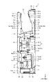
- FIG. 5 is a front view of the hand dryer 1 according to Embodiment 1, showing a state in which the maintenance panel 6 is removed.
- An operation unit 20 is installed in the casing 5b.
- the operation unit 20 includes a switch for turning on/off the power of the air flow generation unit 3, a switch for switching the air volume of the air flow generation unit 3, a switch for turning on/off the power of the heater 17 for warming the air flow, and a power supply for the air cleaning unit 5.
- a switch for switching on and off, a switch for switching the air volume of the blower 5a of the air cleaner 5, and a lamp for displaying each setting state are provided.
- the power lamp of the airflow generating unit 3 and the power lamp of the air cleaning unit 5 can be visually recognized from the outside of the housing 2 through a transmissive portion (not shown) provided on the maintenance panel 6 .
- the transmissive part is, for example, a part of the maintenance panel 6 made transparent, or a hole penetrating the maintenance panel 6 .
- the panel detection unit 19 detects whether the maintenance panel 6 is attached to the housing 2 or not.
- the panel detection unit 19 is arranged on the back side of the portion of the fixed panel 18 that overlaps the maintenance panel 6 .
- the panel detection unit 19 is arranged inside the housing 2 so as not to be visible when the maintenance panel 6 is removed from the housing 2 .
- a mechanical switch is used for the panel detector 19 .
- a mechanical switch is, for example, a limit switch. When such a mechanical switch is used, a part of the maintenance panel 6 attached to the housing 2 presses the contact portion of the panel detection unit 19, whereby the maintenance panel 6 is attached to the housing 2. can be detected.
- an optical switch may be used for the panel detector 19 .
- An optical switch is, for example, an infrared sensor.
- the detection level of the optical switch changes when the maintenance panel 6 is attached to the housing 2, and the presence or absence of the maintenance panel 6 can be detected from the change in the detection level.
- the panel detection section 19 is electrically connected to a control section 21 which will be described later. A detection result of the panel detection section 19 is sent to the control section 21 .
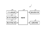
- FIG. 6 is a functional block diagram of the hand dryer 1 according to the first embodiment.
- the control unit 21 controls the operation and stoppage of the airflow generation unit 3 and the operation and stoppage of the air cleaning unit 5 .
- the control unit 21 causes the air flow generating unit 3 and the air cleaning unit 5 to operate when the user's hands are detected by the first hand detecting unit 8 and the second hand detecting unit 9 .
- the control unit 21 operates the air cleaning unit 5 .
- the control unit 21 operates the air cleaning unit 5 at the maximum air volume until a preset set time elapses after the air flow generation unit 3 stops, and operates the air flow generation unit 3 at the maximum air volume after the elapse of the set time. Operate with an air volume smaller than the air volume.
- the control unit 21 stops the air cleaning unit 5 while the airflow generating unit 3 is in operation.
- the control unit 21 energizes the air flow generating unit 3 and the air cleaning unit 5 when the panel detection unit 19 detects removal of the maintenance panel 6 while the air flow generating unit 3 and the air cleaning unit 5 are being energized. Stop.
- the control unit 21 is implemented by a processing circuit.
- the processing circuit may be a control circuit comprising a processor, or may be dedicated hardware.
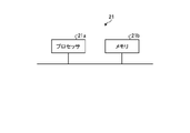
- FIG. 7 is a block diagram showing the hardware configuration of the controller 21 according to the first embodiment.
- a control circuit that implements the control unit 21 includes a processor 21a and a memory 21b as shown in FIG.
- the processor 21a and memory 21b can transmit and receive data to and from each other, for example, via a bus.
- the processor 21a executes the functions of the control unit 21 by reading and executing programs stored in the memory 21b.
- the processor 21a includes, for example, one or more of a CPU (Central Processing Unit) and a DSP (Digital Signal Processor).
- the memory 21b includes one or more of RAM (Random Access Memory), ROM (Read Only Memory), flash memory, EPROM (Erasable Programmable Read Only Memory), and EEPROM (registered trademark) (Electrically Erasable Programmable Read Only Memory).
- RAM Random Access Memory
- ROM Read Only Memory
- flash memory EPROM (Erasable Programmable Read Only Memory)
- EEPROM registered trademark
- the program stored in the memory 21b is provided by, for example, a recording medium.
- the recording medium includes one or more of nonvolatile or volatile semiconductor memory, magnetic disk, flexible memory, optical disk, compact disk, and DVD (Digital Versatile Disc).
- the program stored in the memory 21b may be provided by a communication medium.
- the processing circuit includes, for example, at least one or more of FPGA (Field Programmable Gate Array), ASIC (Application Specific Integrated Circuit), and system LSI (Large Scale Integration).
- the first hand A detection unit 8 and a second hand detection unit 9 detect the user's hand inserted into the hand drying chamber 7 .
- the first hand detecting section 8 detects the user's position when the hand is inserted into the hand drying chamber 7. to detect the hand.
- the second hand-detecting portion 9 detects the user's hand inserted in the hand-drying chamber 7. To detect.
- the control unit 21 controls the air flow generation unit 3 drive the
- the airflow generating section 3 When the airflow generating section 3 is operated, the air outside the housing 2 passes through the air intake filter 15 and is sucked into the first air intake air passage 10a through the first air intake 12. An air flow is generated from to the nozzle 4 .
- the airflow generated by the airflow generating section 3 is routed from the exhaust side of the airflow generating section 3 to the first front side exhaust air passage 10c, and from the exhaust side of the airflow generating section 3 to the first back side. It is divided into a path flowing to the exhaust air passage 10d.
- the airflow that has flowed through the first front-side exhaust air passage 10c is jetted toward the hand drying chamber 7 from the front-side first nozzles 4a.
- the air flow that has flowed through the first rear-side exhaust air passage 10d is jetted toward the hand drying chamber 7 from each of the rear-side first nozzles 4b and the rear-side second nozzles 4c.
- By hitting the user's hand with the jetted air flow it is possible to blow away the moisture adhering to the user's hand and dry the wet hand after washing.
- the blown moisture scatters in the hand drying chamber 7 and is stored in the drain tank 16 through a drainage port (not shown) formed in the bottom wall 7c through a drainage channel.
- the control unit 21 stops the air flow generation unit 3 when the user's hand is no longer detected by at least one of the first hand detection unit 8 and the second hand detection unit 9 .
- the ejection axis of the first rear nozzle 4b is inclined downward by more than 0° and 30° or less than the angle of the ejection axis of the second rear nozzle 4c.
- the first rear nozzle 4b and the second rear nozzle 4c are vertically separated by at least 10 mm. In this way, the airflow jetted from the rear-side first nozzle 4b and the airflow jetted from the rear-side second nozzle 4c do not merge until they hit the back of the user's hand.
- the airflow jetted from the rear-side first nozzle 4b becomes an airflow that flows upward along the user's hand
- the airflow jetted from the rear-side second nozzle 4c becomes an airflow that flows upward along the user's hand.
- it becomes an air current that flows downward along the hand.
- the water blown off the back of the hand is also carried by the swirling air current toward the rear side wall 7e, so that it is possible to prevent the water from scattering from the hand drying chamber 7 toward the user.
- the second front nozzle for communicating the first front exhaust air passage 10c and the hand drying chamber 7 is arranged above the first front nozzle 4a. It may be arranged away from the nozzle 4a. By doing so, it is possible to obtain the same effect as the effect obtained by using the rear-side first nozzle 4b and the rear-side second nozzle 4c. That is, even on the palm side, it is possible to prevent upward airflow from being discharged upward from the hand drying chamber 7, and to prevent water from scattering from the hand drying chamber 7 toward the user.
- FIG. 8 is a flowchart for explaining the operation of the hand dryer 1 according to the first embodiment during air cleaning.
- step S1 When the hand dryer 1 is powered on, the hand dryer 1 enters a standby state in step S1. In the standby state of the hand dryer 1, the air flow generating section 3 and the air cleaning section 5 are stopped, but the air flow generating section 3 and the air cleaning section 5 are energized.
- control unit 21 controls first hand detection unit 8 and second hand detection unit 9 based on detection signals from first hand detection unit 8 and second hand detection unit 9, respectively. Determine whether the user's hand is detected in both. If No in step S2, that is, if it is determined that the user's hand is not detected in at least one of the first hand detection unit 8 and the second hand detection unit 9, the determination in step S2 is repeated. done.
- step S2 determines whether both the first hand detection unit 8 and the second hand detection unit 9 have detected the user's hand. If Yes in step S2, that is, if it is determined that both the first hand detection unit 8 and the second hand detection unit 9 have detected the user's hand, the process proceeds to step S3. In step S3, the controller 21 causes the airflow generator 3 to operate.
- control unit 21 controls first hand detection unit 8 and second hand detection unit 9 based on detection signals from first hand detection unit 8 and second hand detection unit 9, respectively. Determine whether the user's hand is detected in both. If Yes in step S4, that is, if it is determined that the user's hand is detected by both the first hand detection unit 8 and the second hand detection unit 9, the determination in step S4 is repeated. .
- step S4 determines whether the user's hand is not detected by at least one of the first hand detection unit 8 and the second hand detection unit 9.
- step S5 the control section 21 stops the air flow generating section 3 .
- step S6 the control unit 21 operates the air cleaning unit 5 at the maximum air volume.
- strong operation mode the mode in which the air purifier 5 operates with the maximum air volume.
- step S ⁇ b>7 the control unit 21 determines whether or not a set time has elapsed since the operation of the air cleaning unit 5 was started. In the case of No in step S7, that is, when it is determined that the set time has not elapsed since the start of operation of the air purifier 5, the determination of step S7 is repeated.
- step S7 the control unit 21 operates the air cleaning unit 5 with an air volume smaller than the maximum air volume.
- the mode in which the air purifier 5 operates with an air volume smaller than the maximum air volume is referred to as a "weak operation mode".
- step S ⁇ b>9 the control unit 21 stops the air cleaning unit 5 after a certain period of time has passed since the operation of the air cleaning unit 5 started.
- the fixed time is longer than the set time.
- step S10 the hand dryer 1 enters a standby state. The operations from step S1 to step S10 are repeated until the hand dryer 1 is powered off.
- the air cleaning operation of the hand dryer 1 is not limited to the above operation examples.
- the switch for turning on/off the power of the air purifier 5 provided in the operation unit 20 is set to "on" and the hand dryer 1 is energized, the air purifier 5 is always operated. can be By doing so, the air around the hand dryer 1 can be cleaned regardless of the amount of operation of the airflow generating section 3 .
- control unit 21 may control the operation and stop of the air cleaning unit 5 based on the day of the week and the time.
- the hand dryer 1 is provided with a timer for grasping the day of the week and the time, and the controller 21 acquires the day of the week and the time from the timer.
- the control unit 21 may automatically control the air purifying unit 5 not to operate, or may automatically control the air purifying unit 5 to switch to the weak operation mode. . By doing so, the power consumption of the hand dryer 1 can be suppressed.
- it is not necessary to operate the air cleaning unit 5 in the strong operation mode and even if the air cleaning unit 5 is operated in the weak operation mode, the air around the hand dryer 1 can be sufficiently cleaned. can.
- control unit 21 includes a storage unit (not shown), which stores data on the number of operations and the operation time of the air flow generation unit 3, and data on the number of operations, the operation time and the operation mode of the air purification unit 5. may be stored.
- the control unit 21 can switch the operation mode of the air cleaning unit 5 based on the data stored in the storage unit. For example, the control unit 21 calculates a time period in which the hand dryer 1 is used frequently from the data stored in the storage unit, and sets the air cleaning unit 5 to the strong operation mode in advance before the time period in which the number of times of use is high. You can switch. As a result, the air around the hand dryer 1 can be cleaned before the number of times the hand dryer 1 is used increases.
- control unit 21 may store the number of times of operation per certain period of time, and switch the operation mode of the air purification unit 5 depending on whether the number of times of operation per certain period of time exceeds the set number of times. While the number of times the hand dryer 1 is used is small, the number of times it is operated per fixed period of time is small, and the need to clean the air around the hand dryer 1 is low. On the other hand, as the number of times the hand dryer 1 is used increases, the number of times it is operated per fixed period of time also increases, and the air around the hand dryer 1 needs to be cleaned.
- control unit 21 switches the air cleaning unit 5 to the strong operation mode when the number of times of operation per certain time exceeds the set number of times, and when the number of times of operation per certain time does not exceed the set number of times. , the air purifier 5 may be switched to the weak operation mode.
- FIG. 9 is a flow chart for explaining the operation when the maintenance panel 6 of the hand dryer 1 according to the first embodiment is removed.
- the hand dryer 1 When the hand dryer 1 is powered on, the hand dryer 1 enters a standby state in step S11. In the standby state of the hand dryer 1, the air flow generating section 3 and the air cleaning section 5 are stopped, but the air flow generating section 3 and the air cleaning section 5 are energized.
- step S12 the control section 21 determines whether or not the maintenance panel 6 has been detected based on the detection signal from the panel detection section 19 . If Yes in step S12, that is, if it is determined that the maintenance panel 6 has been detected, the determination in step S12 is repeated.
- step S12 determines whether the maintenance panel 6 has been detected. If No in step S12, that is, if it is determined that the maintenance panel 6 has not been detected, the process proceeds to step S13.
- step S ⁇ b>13 the control unit 21 stops energizing the air flow generating unit 3 and the air cleaning unit 5 . At this time, the control unit 21 instantly stops the energization of the discharge device 5e of the air cleaning unit 5.
- FIG. The above operations from step S11 to step S13 are repeated until the hand dryer 1 is powered off.
- the airflow jetted from the nozzle 4 shown in FIG. 2 hits the user's hands and the surface of the inner wall of the hand drying chamber 7, and then is discharged around the housing 2 from the upper opening 7a and the side opening 7b. be done.
- the amount of air discharged from the upper surface opening 7a is smaller due to the provision of the rear-side second nozzles 4c compared to the case where the rear-side second nozzles 4c are not provided. Since the air discharged from the upper opening 7a and the side opening 7b contacts the user's hands and the surface of the inner wall of the hand drying chamber 7, it may be unsanitary depending on the degree of washing by the user. be. Although the hand drying room 7 is regularly cleaned, it may become unsanitary depending on the frequency and method of cleaning.
- the hand dryer 1 has a hand drying chamber 7 which is open on at least one side and into which a hand can be inserted, a first air passage 10 through which air flows, and the first air passage 10 which is independent of A box-shaped housing 2 is provided in which a second air passage 11, which is an air passage through which air flows, is formed.
- the hand dryer 1 includes an air flow generation unit 3 installed in the first air passage 10 to generate an air flow, and an air cleaning unit installed in the second air passage 11 to clean the air. 5.
- the housing 2 has a first intake port 12 for sucking the air outside the housing 2 into the first air passage 10 and the air outside the housing 2 into the second air passage 11.
- the first intake port 12 and the second intake port 13 are formed independently of each other. With these configurations, the air discharged from the hand drying chamber 7 is guided from the second air inlet 13 through the second air passage 11 to the air cleaning unit 5 and cleaned by the air cleaning unit 5. After that, it is discharged to the outside of the housing 2 through the exhaust port 14 . Therefore, the air around the hand dryer 1 can be cleaned. That is, the air discharged from the hand drying chamber 7 can be efficiently cleaned by the air cleaner 5 before the air discharged from the hand drying chamber 7 spreads.
- the second air inlet 13 is formed on the same surface of the housing 2 as the side opening 7b of the hand drying chamber 7, that is, on the side surfaces 2e and 2f of the housing 2.
- the air discharged from the side opening 7b is easily sucked into the second intake port 13.
- the air discharged from the side opening 7b can be efficiently cleaned by the air cleaner 5.
- the first air inlet 12 and the second air inlet 13 are formed independently of each other, and along the surface of the housing 2 are side openings.
- the shortest distance from the edge of the side opening 7b to the second air intake 13 is shorter than the shortest distance from the edge of the side opening 7b to the first air intake 12 along the surface of the housing 2.
- the air discharged from 7b is more likely to be sucked into the second intake port 13 than through the first intake port 12. - ⁇ Therefore, the air discharged from the side opening 7b can be efficiently cleaned by the air cleaner 5. As shown in FIG.
- the first intake port 12 and the exhaust port 14 are formed on the same surface of the housing 2, that is, on the bottom surface 2a of the housing 2. After the air cleaned by the cleaning unit 5 is discharged from the exhaust port 14, it is easily sucked into the first intake port 12. - ⁇ Therefore, the air cleaned by the air cleaner 5 is jetted from the nozzle 4 into the hand drying chamber 7, so that the user's hands can be sanitarily dried.
- the second intake port 13 and the second exhaust port 14 are formed on different surfaces of the housing 2, so that the air is cleaned by the air cleaning unit 5. After the air is discharged from the exhaust port 14, it becomes difficult to be sucked into the second intake port 13. - ⁇
- the second air passage 11 is provided independently of the first air passage 10 in which the air flow generating section 3 is arranged, and the air cleaning section having the blower 5a and the discharge device 5e is provided. 5 is arranged in the second air passage 11 .
- a motor that consumes less power than the first motor 3b of the air flow generating section 3 can be used for the second motor 5d of the air cleaning section 5, so that the amount of electricity used can be reduced. can.
- the hand dryer 1 detects the hand of the user by the first hand detection unit 8 and the second hand detection unit 9, and the airflow generation unit 3 and a control unit 21 for operating the air cleaning unit 5.
- the hand dryer 1 includes a maintenance panel 6 that is detachably attached to the housing 2 and covers the air purifier 5 while being attached to the housing 2, and the maintenance panel 6 is attached to the housing. and a panel detector 19 for detecting whether or not it is attached to the body 2 .
- the control unit 21 stops energization of the discharge device 5e of the air purifying unit 5 when the panel detecting unit 19 detects removal of the maintenance panel 6 while the air flow generating unit 3 and the air purifying unit 5 are energized. .
- control unit 21 stops the airflow generation unit 3 when the panel detection unit 19 detects removal of the maintenance panel 6 while the airflow generation unit 3 and the air cleaning unit 5 are being energized. . Thereby, it is possible to prevent the air flow from being jetted from the nozzle 4 during the maintenance work.
- the control unit 21 stops the airflow generation unit 3 while the airflow generation unit 3 is in operation, and operates the air cleaning unit 5 after the airflow generation unit 3 is stopped.
- the control unit 21 operates the air cleaning unit 5 at the maximum air volume until a preset set time elapses after the air flow generation unit 3 stops, and after the elapse of the set time, the air flow generation unit 3 is operated at an air volume smaller than the maximum air volume.
- the air purifying unit 5 arranged in the air flow generating unit 3 has a blower 5 a independent of the air flow generating unit 3 .
- the air can be cleaned by the air cleaner 5 when the air flow generator 3 is operated to dry the hands.
- FIG. 10 is a side view of hand dryer 1A according to the second embodiment.
- This embodiment differs from the first embodiment in the position of the second intake port 13 .
- symbol is attached
- FIG. 1 is omitted from illustration.
- the upper surface 2b of the housing 2 is formed in a stepped shape.
- the second intake port 13 is formed on the vertical surface of the upper surface 2b of the housing 2 facing the hand drying chamber 7 on the rear surface 2d side of the housing 2 relative to the hand drying chamber 7 .
- the second intake port 13 is arranged near the top opening 7a.
- the second intake port 13 is arranged above the upper surface opening 7a and closer to the rear surface 2d than the upper surface opening 7a.
- the hand drying chamber 7 is opened only on the upper surface 2b of the housing 2 in this embodiment, but may be opened on the left and right side surfaces 2e and 2f of the housing 2 as well. In this case, the second air intake 13 may be arranged near the side opening 7b.
- the second air intake air passage 11a of the second air passage 11 extends rearward from the second air intake port 13 toward the back surface 2d and then extends downward along the back surface 2d, and the air cleaning unit 5 is further arranged. Extends forward towards the air path where the A second exhaust air passage 11 b of the second air passage 11 extends vertically along the front surface 2 c of the housing 2 .
- the air discharged from the upper opening 7a is more easily sucked into the air cleaner 5 (not shown) through the second intake port 13 . Therefore, the air discharged from the upper opening 7a can be efficiently cleaned by the air cleaner 5. As shown in FIG.
- FIG. 11 is a side view of a hand dryer 1B according to Modification 1 of Embodiment 2.
- the second intake port 13 is formed on the upper surface 2b of the housing 2 on the front surface 2c side of the housing 2 relative to the hand drying chamber 7. As shown in FIG. That is, the second intake port 13 is formed between the user and the hand drying chamber 7 .
- the second intake port 13 is arranged near the top opening 7a.
- the second intake port 13 is arranged above the upper surface opening 7a and closer to the front surface 2c than the upper surface opening 7a.
- the hand drying chamber 7 is opened only on the upper surface 2b of the housing 2 in this embodiment, but may be opened on the left and right side surfaces 2e and 2f of the housing 2 as well. In this case, the second air intake 13 may be arranged near the side opening 7b.
- the second air intake air passage 11a of the second air passage 11 extends downward along the front surface 2c from the second air intake port 13 and then extends rearward. extending downwards towards the road.
- a second exhaust air passage 11 b of the second air passage 11 extends vertically along the front surface 2 c of the housing 2 .
- the air directed toward the user is more easily sucked through the second air inlet 13 by the air purifier 5 (not shown). Therefore, the air discharged from the upper opening 7a can be efficiently cleaned by the air cleaner 5. As shown in FIG.
- FIG. 12 is a side view of a hand dryer 1C according to Modification 2 of Embodiment 2.
- FIG. The configurations of the second intake port 13 and the second intake air passage 11a are the same as those of the second embodiment.
- the exhaust port 14 is formed on the upper surface 2b of the housing 2 on the front surface 2c side of the housing 2 relative to the hand drying chamber 7 . That is, the exhaust port 14 is formed between the user and the hand drying chamber 7 .
- the exhaust port 14 is arranged near the top opening 7a.
- the exhaust port 14 is arranged above the upper opening 7a and closer to the front surface 2c than the upper opening 7a.
- the hand drying chamber 7 is opened only on the upper surface 2b of the housing 2 in this embodiment, but may be opened on the left and right side surfaces 2e and 2f of the housing 2 as well.
- the exhaust port 14 may be arranged near the side opening 7b.
- the second exhaust air duct 11b of the second air duct 11 extends upward from the air duct in which the air cleaning unit 5 is arranged, then extends forward toward the front 2c, and further upward along the front 2c. extended.
- the air purified by the air purifier 5 is discharged between the user and the hand drying chamber 7, so that the hands can be dried with the purified air.
- the exhaust port 14 may open toward the hand drying chamber 7 . This makes it easier for the clean air discharged from the exhaust port 14 to flow into the hand drying chamber 7 . Therefore, when the user's hands are dried and the air cleaning unit 5 is operated at the same time, the user's hands can be exposed to clean air, and the user's hands can be sanitarily dried. Also, when the user's hands are not dried, clean air is discharged from the exhaust port 14 toward the hand drying chamber 7, so that the surface of the inner wall of the hand drying chamber 7 can be kept clean.
Landscapes
- Health & Medical Sciences (AREA)
- Public Health (AREA)
- Drying Of Solid Materials (AREA)
- Domestic Plumbing Installations (AREA)
Priority Applications (3)
| Application Number | Priority Date | Filing Date | Title |
|---|---|---|---|
| PCT/JP2021/006885 WO2022180694A1 (ja) | 2021-02-24 | 2021-02-24 | 手乾燥装置 |
| JP2023501723A JP7378661B2 (ja) | 2021-02-24 | 2021-02-24 | 手乾燥装置 |
| TW110125594A TWI799914B (zh) | 2021-02-24 | 2021-07-13 | 手乾燥裝置 |
Applications Claiming Priority (1)
| Application Number | Priority Date | Filing Date | Title |
|---|---|---|---|
| PCT/JP2021/006885 WO2022180694A1 (ja) | 2021-02-24 | 2021-02-24 | 手乾燥装置 |
Publications (1)
| Publication Number | Publication Date |
|---|---|
| WO2022180694A1 true WO2022180694A1 (ja) | 2022-09-01 |
Family
ID=83047855
Family Applications (1)
| Application Number | Title | Priority Date | Filing Date |
|---|---|---|---|
| PCT/JP2021/006885 Ceased WO2022180694A1 (ja) | 2021-02-24 | 2021-02-24 | 手乾燥装置 |
Country Status (3)
| Country | Link |
|---|---|
| JP (1) | JP7378661B2 (https=) |
| TW (1) | TWI799914B (https=) |
| WO (1) | WO2022180694A1 (https=) |
Cited By (1)
| Publication number | Priority date | Publication date | Assignee | Title |
|---|---|---|---|---|
| WO2024185011A1 (ja) * | 2023-03-06 | 2024-09-12 | 三菱電機株式会社 | 手乾燥装置 |
Citations (3)
| Publication number | Priority date | Publication date | Assignee | Title |
|---|---|---|---|---|
| JP2006081925A (ja) * | 2005-11-11 | 2006-03-30 | Toto Ltd | 手乾燥装置 |
| JP2010088621A (ja) * | 2008-10-07 | 2010-04-22 | Mitsubishi Electric Corp | 手乾燥装置 |
| JP2010178970A (ja) * | 2009-02-06 | 2010-08-19 | Sharp Corp | 手乾燥装置 |
Family Cites Families (2)
| Publication number | Priority date | Publication date | Assignee | Title |
|---|---|---|---|---|
| CN200957055Y (zh) * | 2006-09-08 | 2007-10-10 | 安徽科技学院 | 负离子杀菌烘手机 |
| WO2015128988A1 (ja) * | 2014-02-27 | 2015-09-03 | 三菱電機株式会社 | 手乾燥装置 |
-
2021
- 2021-02-24 WO PCT/JP2021/006885 patent/WO2022180694A1/ja not_active Ceased
- 2021-02-24 JP JP2023501723A patent/JP7378661B2/ja active Active
- 2021-07-13 TW TW110125594A patent/TWI799914B/zh active
Patent Citations (3)
| Publication number | Priority date | Publication date | Assignee | Title |
|---|---|---|---|---|
| JP2006081925A (ja) * | 2005-11-11 | 2006-03-30 | Toto Ltd | 手乾燥装置 |
| JP2010088621A (ja) * | 2008-10-07 | 2010-04-22 | Mitsubishi Electric Corp | 手乾燥装置 |
| JP2010178970A (ja) * | 2009-02-06 | 2010-08-19 | Sharp Corp | 手乾燥装置 |
Cited By (1)
| Publication number | Priority date | Publication date | Assignee | Title |
|---|---|---|---|---|
| WO2024185011A1 (ja) * | 2023-03-06 | 2024-09-12 | 三菱電機株式会社 | 手乾燥装置 |
Also Published As
| Publication number | Publication date |
|---|---|
| TW202233112A (zh) | 2022-09-01 |
| TWI799914B (zh) | 2023-04-21 |
| JP7378661B2 (ja) | 2023-11-13 |
| JPWO2022180694A1 (https=) | 2022-09-01 |
Similar Documents
| Publication | Publication Date | Title |
|---|---|---|
| JP5923835B2 (ja) | 手乾燥装置 | |
| JP5923834B2 (ja) | 手乾燥装置 | |
| NZ565370A (en) | Drying apparatus | |
| EP1912551B1 (en) | Hand dryer | |
| JP7378661B2 (ja) | 手乾燥装置 | |
| JP2022174975A (ja) | 手乾燥装置 | |
| KR20140093680A (ko) | 손 건조 장치 | |
| JP3770255B2 (ja) | 手乾燥装置 | |
| JPH1176099A (ja) | 手乾燥装置 | |
| JP3993778B2 (ja) | 手乾燥装置 | |
| JP6072607B2 (ja) | 手乾燥装置 | |
| JP2001299636A (ja) | 手乾燥装置 | |
| JP2005087283A (ja) | 手乾燥装置 | |
| JP3747924B2 (ja) | 手乾燥装置 | |
| JP7085119B2 (ja) | 便座装置及びトイレ装置 | |
| JPWO2022180694A5 (https=) | ||
| JP7504683B2 (ja) | ハンドドライヤ | |
| JP2004321485A (ja) | 手乾燥装置 | |
| JP2006187396A (ja) | 手乾燥装置 | |
| JP2004097741A (ja) | 手指乾燥装置 | |
| JP3832224B2 (ja) | 手乾燥装置 | |
| JP3817817B2 (ja) | 手乾燥装置 | |
| JP2024123922A (ja) | 手乾燥装置及び手乾燥装置の制御方法 | |
| JP2018004135A (ja) | 浴室換気装置 | |
| JP5585287B2 (ja) | 手乾燥装置 |
Legal Events
| Date | Code | Title | Description |
|---|---|---|---|
| 121 | Ep: the epo has been informed by wipo that ep was designated in this application |
Ref document number: 21927797 Country of ref document: EP Kind code of ref document: A1 |
|
| ENP | Entry into the national phase |
Ref document number: 2023501723 Country of ref document: JP Kind code of ref document: A |
|
| NENP | Non-entry into the national phase |
Ref country code: DE |
|
| 122 | Ep: pct application non-entry in european phase |
Ref document number: 21927797 Country of ref document: EP Kind code of ref document: A1 |