WO2022177028A1 - 画像処理方法、画像処理装置、及びプログラム - Google Patents
画像処理方法、画像処理装置、及びプログラム Download PDFInfo
- Publication number
- WO2022177028A1 WO2022177028A1 PCT/JP2022/007393 JP2022007393W WO2022177028A1 WO 2022177028 A1 WO2022177028 A1 WO 2022177028A1 JP 2022007393 W JP2022007393 W JP 2022007393W WO 2022177028 A1 WO2022177028 A1 WO 2022177028A1
- Authority
- WO
- WIPO (PCT)
- Prior art keywords
- image
- volume data
- oct
- stereoscopic image
- blood vessels
- Prior art date
Links
- 238000003672 processing method Methods 0.000 title claims abstract description 12
- 210000004204 blood vessel Anatomy 0.000 claims abstract description 108
- 210000003462 vein Anatomy 0.000 claims abstract description 44
- 210000003161 choroid Anatomy 0.000 claims abstract description 20
- 239000003708 ampul Substances 0.000 claims description 8
- 230000002194 synthesizing effect Effects 0.000 claims description 2
- 238000012014 optical coherence tomography Methods 0.000 abstract description 106
- 230000003287 optical effect Effects 0.000 description 56
- 238000005516 engineering process Methods 0.000 description 25
- 210000001508 eye Anatomy 0.000 description 22
- 238000010586 diagram Methods 0.000 description 20
- 238000003384 imaging method Methods 0.000 description 19
- 238000005286 illumination Methods 0.000 description 13
- 238000000605 extraction Methods 0.000 description 11
- 230000006870 function Effects 0.000 description 10
- 239000000284 extract Substances 0.000 description 8
- 238000001514 detection method Methods 0.000 description 6
- 238000000034 method Methods 0.000 description 6
- 238000005259 measurement Methods 0.000 description 5
- 210000001747 pupil Anatomy 0.000 description 5
- 230000004323 axial length Effects 0.000 description 4
- 210000005252 bulbus oculi Anatomy 0.000 description 4
- 238000004891 communication Methods 0.000 description 4
- 238000004590 computer program Methods 0.000 description 4
- 238000003745 diagnosis Methods 0.000 description 4
- 238000013473 artificial intelligence Methods 0.000 description 3
- 238000004364 calculation method Methods 0.000 description 3
- 230000002093 peripheral effect Effects 0.000 description 3
- 238000007781 pre-processing Methods 0.000 description 3
- 206010025421 Macule Diseases 0.000 description 2
- 238000002583 angiography Methods 0.000 description 2
- 230000008602 contraction Effects 0.000 description 2
- 201000010099 disease Diseases 0.000 description 2
- 208000037265 diseases, disorders, signs and symptoms Diseases 0.000 description 2
- 238000001914 filtration Methods 0.000 description 2
- 210000003733 optic disk Anatomy 0.000 description 2
- 210000001525 retina Anatomy 0.000 description 2
- 230000011218 segmentation Effects 0.000 description 2
- 238000004458 analytical method Methods 0.000 description 1
- 238000009530 blood pressure measurement Methods 0.000 description 1
- 210000002919 epithelial cell Anatomy 0.000 description 1
- 230000004438 eyesight Effects 0.000 description 1
- 230000004907 flux Effects 0.000 description 1
- 238000010191 image analysis Methods 0.000 description 1
- 238000007689 inspection Methods 0.000 description 1
- 230000004410 intraocular pressure Effects 0.000 description 1
- 230000008447 perception Effects 0.000 description 1
- 210000003583 retinal pigment epithelium Anatomy 0.000 description 1
- 230000002123 temporal effect Effects 0.000 description 1
- 230000004304 visual acuity Effects 0.000 description 1
- 230000000007 visual effect Effects 0.000 description 1
Images


Classifications
-
- G—PHYSICS
- G06—COMPUTING; CALCULATING OR COUNTING
- G06T—IMAGE DATA PROCESSING OR GENERATION, IN GENERAL
- G06T17/00—Three dimensional [3D] modelling, e.g. data description of 3D objects
-
- A—HUMAN NECESSITIES
- A61—MEDICAL OR VETERINARY SCIENCE; HYGIENE
- A61B—DIAGNOSIS; SURGERY; IDENTIFICATION
- A61B3/00—Apparatus for testing the eyes; Instruments for examining the eyes
- A61B3/10—Objective types, i.e. instruments for examining the eyes independent of the patients' perceptions or reactions
-
- G—PHYSICS
- G06—COMPUTING; CALCULATING OR COUNTING
- G06T—IMAGE DATA PROCESSING OR GENERATION, IN GENERAL
- G06T19/00—Manipulating 3D models or images for computer graphics
-
- G—PHYSICS
- G06—COMPUTING; CALCULATING OR COUNTING
- G06T—IMAGE DATA PROCESSING OR GENERATION, IN GENERAL
- G06T2210/00—Indexing scheme for image generation or computer graphics
- G06T2210/41—Medical
Definitions
- the technology of the present disclosure relates to an image processing method, an image processing device, and a program.
- US Patent No. 10238281 discloses a technique for generating volume data of an eye to be examined using an optical coherence tomography. Conventionally, it has been desired to visualize blood vessels based on volume data of an eye to be examined.
- An image processing method is an image processing method performed by a processor, comprising: acquiring OCT volume data including a choroid; extracting choroidal blood vessels based on the OCT volume data; and generating a stereoscopic image of the choroidal vessels.
- An image processing apparatus includes a memory and a processor connected to the memory, the processor acquiring OCT volume data including a choroid; and extracting a choroidal blood vessel using a method to generate a stereoscopic image of the choroidal blood vessel.
- a program causes a computer to acquire OCT volume data including a choroid, extract choroidal blood vessels based on the OCT volume data, and generate a stereoscopic image of the choroidal blood vessels. Execute the step and
- FIG. 1 is a schematic configuration diagram of an ophthalmologic system of this embodiment
- FIG. 1 is a schematic configuration diagram of an ophthalmologic apparatus according to an embodiment
- FIG. 3 is a schematic configuration diagram of a server
- FIG. FIG. 4 is an explanatory diagram of functions realized by an image processing program in the CPU of the server
- 4 is a flowchart showing image processing by a server
- FIG. 6 is a flow chart showing vortex vein stereoscopic image generation processing in step 6100 of FIG. 5
- FIG. FIG. 4 is a schematic diagram showing the relationship between the eyeball and the position of the vortex vein
- FIG. 4 is a diagram showing the relationship between OCT volume data and an en-face image; Schematic diagram of 3D image of vortex veins It is a first example of a display screen using a stereoscopic image of vortex veins. This is a second example of a display screen using a stereoscopic image of vortex veins.
- FIG. 11B is a third example of a display screen using a stereoscopic image of vortex veins.
- FIG. This is a fourth example of a display screen using a stereoscopic image of vortex veins.
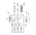
- FIG. 1 shows a schematic configuration of an ophthalmic system 100.
- the ophthalmologic system 100 includes an ophthalmologic apparatus 110 , a server apparatus (hereinafter referred to as “server”) 140 , and a display apparatus (hereinafter referred to as “viewer”) 150 .
- the ophthalmologic device 110 acquires a fundus image.
- the server 140 associates a plurality of fundus images obtained by photographing the fundus of a plurality of patients with the ophthalmologic apparatus 110 and the axial length measured by an axial length measuring device (not shown) with the patient ID. memorize.
- the viewer 150 displays the fundus image acquired by the server 140 and the analysis results.
- the server 140 is an example of the "image processing device" of the technology of the present disclosure.
- Network 130 is any network such as LAN, WAN, the Internet, or a wide area Ethernet network.
- LAN local area network
- WAN wide area network
- Ethernet wide area Ethernet network
- the viewer 150 is a client in a client-server system, and a plurality of viewers 150 are connected via a network. Also, a plurality of servers 140 may be connected via a network in order to ensure system redundancy.
- the ophthalmologic apparatus 110 has an image processing function and an image viewing function of the viewer 150, the ophthalmologic apparatus 110 can acquire, process, and view fundus images in a stand-alone state.
- the server 140 has the image viewing function of the viewer 150, the configuration of the ophthalmologic apparatus 110 and the server 140 enables fundus image acquisition, image processing, and image viewing.
- ophthalmologic equipment inspection equipment for visual field measurement, intraocular pressure measurement, etc.
- diagnosis support device that performs image analysis using AI (Artificial Intelligence) are connected via the network 130 to the ophthalmic equipment 110, the server 140, and the viewer. 150 may be connected.
- AI Artificial Intelligence
- SLO scanning laser ophthalmoscope
- OCT optical coherence tomography
- the horizontal direction is the "X direction”
- the vertical direction to the horizontal plane is the "Y direction”.
- the ophthalmologic device 110 includes an imaging device 14 and a control device 16 .
- the imaging device 14 includes an SLO unit 18 and an OCT unit 20 and acquires a fundus image of the eye 12 to be examined.
- the two-dimensional fundus image acquired by the SLO unit 18 is hereinafter referred to as an SLO image.
- a tomographic image of the retina, a front image (en-face image), and the like created based on the OCT data acquired by the OCT unit 20 are referred to as OCT images.
- the control device 16 comprises a computer having a CPU (Central Processing Unit) 16A, a RAM (Random Access Memory) 16B, a ROM (Read-Only Memory) 16C, and an input/output (I/O) port 16D. ing.
- CPU Central Processing Unit
- RAM Random Access Memory
- ROM Read-Only Memory
- I/O input/output
- the control device 16 has an input/display device 16E connected to the CPU 16A via an I/O port 16D.
- the input/display device 16E has a graphic user interface that displays an image of the subject's eye 12 and receives various instructions from the user. Graphic user interfaces include touch panel displays.
- the control device 16 also includes an image processor 17 connected to the I/O port 16D.
- the image processor 17 generates an image of the subject's eye 12 based on the data obtained by the imaging device 14 .
- the control device 16 is connected to the network 130 via the communication interface 16F.
- the control device 16 of the ophthalmic device 110 includes the input/display device 16E, but the technology of the present disclosure is not limited to this.
- the controller 16 of the ophthalmic device 110 may not have the input/display device 16E, but may have a separate input/display device physically separate from the ophthalmic device 110.
- the display device includes an image processor unit that operates under the control of the display control section 204 of the CPU 16A of the control device 16.
- FIG. The image processor unit may display an SLO image or the like based on the image signal output by the display control unit 204 .
- the imaging device 14 operates under the control of the CPU 16A of the control device 16.
- the imaging device 14 includes an SLO unit 18 , an imaging optical system 19 and an OCT unit 20 .
- the imaging optical system 19 includes an optical scanner 22 and a wide-angle optical system 30 .
- the optical scanner 22 two-dimensionally scans the light emitted from the SLO unit 18 in the X and Y directions.
- the optical scanner 22 may be any optical element capable of deflecting a light beam, such as a polygon mirror or a galvanomirror. Moreover, those combinations may be sufficient.
- the wide-angle optical system 30 synthesizes the light from the SLO unit 18 and the light from the OCT unit 20.
- the wide-angle optical system 30 may be a reflective optical system using a concave mirror such as an elliptical mirror, a refractive optical system using a wide-angle lens, or a catadioptric system combining concave mirrors and lenses.
- a wide-angle optical system using an elliptical mirror, a wide-angle lens, etc. it is possible to photograph not only the central part of the fundus but also the peripheral part of the retina.
- the wide-angle optical system 30 realizes observation in a wide field of view (FOV: Field of View) 12A at the fundus.
- the FOV 12A indicates a range that can be photographed by the photographing device 14.
- FIG. FOV12A can be expressed as a viewing angle.
- a viewing angle may be defined by an internal illumination angle and an external illumination angle in this embodiment.
- the external irradiation angle is an irradiation angle defined by using the pupil 27 as a reference for the irradiation angle of the light beam irradiated from the ophthalmologic apparatus 110 to the eye 12 to be examined.
- the internal illumination angle is an illumination angle defined by using the eyeball center O as a reference for the illumination angle of the luminous flux that illuminates the fundus F.
- the external illumination angle and the internal illumination angle are in correspondence. For example, an external illumination angle of 120 degrees corresponds to an internal illumination angle of approximately 160 degrees. In this embodiment, the internal illumination angle is 200 degrees.
- UWF-SLO fundus image an SLO fundus image obtained by photographing at an angle of view of 160 degrees or more with an internal irradiation angle is referred to as a UWF-SLO fundus image.
- UWF is an abbreviation for UltraWide Field.
- the wide-angle optical system 30, which has an ultra-wide field of view (FOV) of the fundus, can image the area beyond the posterior pole of the fundus of the eye 12 to be examined and beyond the equator. You can take pictures of existing structures.
- FOV ultra-wide field of view
- the ophthalmologic apparatus 110 can photograph the region 12A with an internal illumination angle of 200° with the eyeball center O of the subject's eye 12 as a reference position.
- the internal illumination angle of 200° is 110° in terms of the external illumination angle with the pupil of the eyeball of the subject's eye 12 as a reference.
- the wide-angle optical system 30 irradiates the laser light from the pupil with an external irradiation angle of 110°, and photographs the fundus region with an internal irradiation angle of 200°.
- the SLO system is implemented by the control device 16, SLO unit 18, and imaging optical system 19 shown in FIG. Since the SLO system includes the wide-angle optical system 30, it enables fundus imaging with a wide FOV 12A.
- the SLO unit 18 includes a B light (blue light) light source 40, a G light (green light) light source 42, an R light (red light) light source 44, and an IR light (infrared (for example, near infrared light)) light source. It comprises a light source 46 and optical systems 48, 50, 52, 54 and 56 that reflect or transmit the light from the light sources 40, 42, 44 and 46 and guide them to one optical path.
- Optical systems 48, 56 are mirrors and optical systems 50, 52, 54 are beam splitters.
- the B light is reflected by the optical system 48, transmitted through the optical system 50, and reflected by the optical system 54, the G light is reflected by the optical systems 50 and 54, and the R light is transmitted by the optical systems 52 and 54.
- the IR light is reflected by optical systems 52 and 56 and directed to one optical path, respectively.
- the SLO unit 18 is configured to be switchable between a light source that emits laser light with different wavelengths, such as a mode that emits R light and G light, and a mode that emits infrared light, or a combination of light sources that emit light.
- a light source that emits laser light with different wavelengths
- the example shown in FIG. 2 includes four light sources, that is, the B light source 40, the G light source 42, the R light source 44, and the IR light source 46
- the technology of the present disclosure is not limited to this.
- the SLO unit 18 may further include a white light source and emit light in various modes such as a mode emitting G light, R light, and B light, and a mode emitting only white light. good.
- the light that has entered the imaging optical system 19 from the SLO unit 18 is scanned in the X and Y directions by the optical scanner 22 .
- the scanning light passes through the wide-angle optical system 30 and the pupil 27 and illuminates the fundus. Reflected light reflected by the fundus enters the SLO unit 18 via the wide-angle optical system 30 and the optical scanner 22 .
- the SLO unit 18 has a beam splitter 64 that reflects the B light from the posterior segment (fundus) of the subject's eye 12 and transmits other than the B light, and G light from the light transmitted through the beam splitter 64 .
- a beam splitter 58 that reflects and transmits light other than G light is provided.
- the SLO unit 18 has a beam splitter 60 that reflects the R light and transmits other than the R light out of the light transmitted through the beam splitter 58 .
- the SLO unit 18 has a beam splitter 62 that reflects IR light out of the light transmitted through the beam splitter 60 .
- the SLO unit 18 includes a B light detection element 70 for detecting B light reflected by the beam splitter 64, a G light detection element 72 for detecting G light reflected by the beam splitter 58, and an R light reflected by the beam splitter 60.
- An R photodetector element 74 and an IR photodetector element 76 for detecting IR light reflected by the beam splitter 62 are provided.
- the light (reflected light reflected by the fundus) that is incident on the SLO unit 18 via the wide-angle optical system 30 and the optical scanner 22 is reflected by the beam splitter 64 and received by the B light detection element 70 in the case of B light.
- the beam splitter 58 In the case of G light, it is reflected by the beam splitter 58 and received by the G light detection element 72 .
- the incident light, in the case of R light passes through the beam splitter 58 , is reflected by the beam splitter 60 , and is received by the R light detection element 74 .
- the incident light, in the case of IR light passes through the beam splitters 58 and 60 , is reflected by the beam splitter 62 , and is received by the IR photodetector 76 .
- the image processor 17 operating under the control of the CPU 16A uses the signals detected by the B photodetector 70, the G photodetector 72, the R photodetector 74, and the IR photodetector 76 to produce a UWF-SLO image. Generate.
- a UWF-SLO image generated using the signal detected by the B photodetector 70 is called a B-UWF-SLO image (B-color fundus image).
- a UWF-SLO image generated using the signals detected by the G photodetector 72 is called a G-UWF-SLO image (G color fundus image).
- a UWF-SLO image generated using the signal detected by the R photodetector 74 is called an R-UWF-SLO image (R color fundus image).
- a UWF-SLO image generated using the signal detected by the IR photodetector 76 is called an IR-UWF-SLO image (IR fundus image).
- UWF-SLO images include these R-color fundus images, G-color fundus images, B-color fundus images, and IR fundus images. Also included is a fluorescence UWF-SLO image of fluorescence.
- control device 16 controls the light sources 40, 42, 44 to emit light simultaneously.
- a G-color fundus image, an R-color fundus image, and a B-color fundus image whose respective positions correspond to each other are obtained.
- An RGB color fundus image is obtained from the G color fundus image, the R color fundus image, and the B color fundus image.
- the control device 16 controls the light sources 42 and 44 to emit light at the same time, and the fundus of the subject's eye 12 is photographed simultaneously with the G light and the R light, thereby obtaining a G-color fundus image and an R-color fundus image corresponding to each other at each position.
- a fundus image is obtained.
- An RG color fundus image is obtained from the G color fundus image and the R color fundus image.
- a full-color fundus image may be generated using the G-color fundus image, the R-color fundus image, and the B-color fundus image.
- the field of view (FOV) of the fundus can be set to a super-wide angle, and the area extending from the posterior pole of the fundus to the equator of the subject's eye 12 can be photographed.
- the OCT system is implemented by the control device 16, OCT unit 20, and imaging optical system 19 shown in FIG. Since the OCT system includes the wide-angle optical system 30, OCT imaging of the peripheral part of the fundus can be performed in the same manner as the SLO fundus image imaging described above. In other words, the wide-angle optical system 30 having a super-wide field of view (FOV) of the fundus can perform OCT imaging of the region extending from the posterior pole of the fundus to the equator 178 of the subject's eye 12 . It is possible to acquire OCT data of structures such as vortex veins that exist in the peripheral part of the eye fundus, and obtain 3D structures of vortex veins by performing image processing on tomographic images of vortex veins and OCT data.
- FOV super-wide field of view
- the OCT unit 20 includes a light source 20A, a sensor (detection element) 20B, a first optical coupler 20C, a reference optical system 20D, a collimating lens 20E, and a second optical coupler 20F.
- the light emitted from the light source 20A is split by the first optical coupler 20C.
- One of the split beams is collimated by the collimating lens 20E and then enters the imaging optical system 19 as measurement light.
- the measurement light passes through the wide-angle optical system 30 and the pupil 27 and illuminates the fundus.
- the measurement light reflected by the fundus enters the OCT unit 20 via the wide-angle optical system 30, and enters the second optical coupler 20F via the collimating lens 20E and the first optical coupler 20C.
- the other light emitted from the light source 20A and branched by the first optical coupler 20C enters the reference optical system 20D as reference light, passes through the reference optical system 20D, and enters the second optical coupler 20F. do.
- the image processor 17 operating under the control of the image processor 206 generates OCT data detected by the sensor 20B. It is also possible for the image processor 17 to generate an OCT image such as a tomographic image or an en-face image based on the OCT data.
- the OCT unit 20 can scan a predetermined range (for example, a rectangular range of 6 mm x 6 mm) in one OCT imaging.
- the predetermined range is not limited to 6 mm x 6 mm, but may be a square range of 12 mm x 12 mm or 23 mm x 23 mm, or a rectangular range such as 14 mm x 9 mm, 6 mm x 3.5 mm, or any rectangular range. can. It may also be in a range of circular diameters such as 6 mm, 12 mm, and 23 mm in diameter.
- the ophthalmologic apparatus 110 can scan the region 12A with an internal irradiation angle of 200°. That is, by controlling the optical scanner 22, OCT imaging of a predetermined range including vortex veins is performed. The ophthalmologic apparatus 110 can generate OCT data through the OCT imaging.
- the ophthalmologic apparatus 110 can generate OCT images such as tomographic images (B-scan images) of the fundus including vortex veins, OCT volume data including vortex veins, and en-face images (OCT images) which are cross sections of the OCT volume data.
- OCT images such as tomographic images (B-scan images) of the fundus including vortex veins, OCT volume data including vortex veins, and en-face images (OCT images) which are cross sections of the OCT volume data.
- a frontal image generated based on the volume data can be generated.
- the OCT image includes an OCT image of the central part of the fundus (the posterior pole part of the eyeball where the macula, the optic papilla, etc. are present).
- the OCT data (or image data of an OCT image) is sent from the ophthalmologic apparatus 110 to the server 140 via the communication interface 16F and stored in the storage device 254.
- the light source 20A exemplifies a wavelength sweep type SS-OCT (Swept-Source OCT). It may be an OCT system of any type.
- SS-OCT Tin-Source OCT
- the server 140 has a computer main body 252 .
- the computer main body 252 has a CPU 262 , a RAM 266 , a ROM 264 and an input/output (I/O) port 268 .
- Input/output (I/O) port 268 is connected to storage device 254 , display 256 , mouse 255 M, keyboard 255 K, and communication interface (I/F) 258 .
- the storage device 254 is composed of, for example, a non-volatile memory.
- Input/output (I/O) port 268 is connected to network 130 via communication interface (I/F) 258 . Accordingly, server 140 can communicate with ophthalmic device 110 and viewer 150 .
- the image processing program shown in FIG. 6 is stored in the ROM 264 or the storage device 254.
- the ROM 264 or storage device 254 is an example of the "memory" of the technology of the present disclosure.
- the CPU 262 is an example of the “processor” of the technology of the present disclosure.
- the image processing program is an example of the "program” of the technology of the present disclosure.
- the server 140 stores each data received from the ophthalmologic apparatus 110 in the storage device 254 .
- the image processing program has a display control function, an image processing function, and a processing function.
- CPU 262 functions as display control unit 204 , image processing unit 206 , and processing unit 208 by executing image processing programs having these functions.
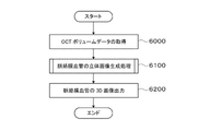
- the CPU 262 of the server 140 executes the image processing program to implement the image processing (image processing method) shown in the flowchart of FIG.
- the image processing unit 206 acquires OCT volume data including the choroid from the storage device 254 .
- the image processing unit 206 extracts choroidal blood vessels based on the OCT volume data, and executes stereoscopic image generation processing (described later) for generating stereoscopic images (3D images) of vortex vein vessels.
- step 6200 the processing unit 208 outputs the generated stereoscopic image (3D image) of the vortex vein blood vessel, specifically, stores it in the RAM 266 or the storage device 254, and ends the image processing.
- the display control unit 204 Based on the user's instruction, the display control unit 204 generates a display screen containing a stereoscopic image of the vortex veins (examples of the display screen are shown in FIGS. 10 to 15, which will be described later).
- the generated display screen is output to the viewer 150 by the processing unit 208 as an image signal.
- a display screen appears on the viewer 150 display.
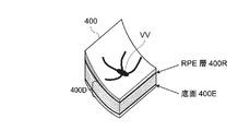
- step 620 of FIG. 6, the image processing unit 206 extracts a region corresponding to the choroid from the OCT volume data 400 (see FIG. 8) acquired in step 6000, and performs OCT of the choroid part based on the extracted region. Extract (acquire) volume data.
- OCT volume data 400 including vortex veins and choroidal blood vessels around the vortex veins will be described as an example of OCT volume data 400D.
- the choroidal vessels refer to the vortex veins and the choroidal vessels surrounding the vortex veins.
- the image processing unit 206 scans the OCT volume data so as to include the vortex veins and the choroidal vessels around the vortex veins.
- OCT volume data 400 of the region where the choroidal vessels exist OCT volume data 400D of the region below the epithelial cell layer 400R (retinal pigment epithelium, hereinafter referred to as RPE layer) is extracted.
- the image processing unit 206 first identifies the RPE layer 400R by performing image processing for identifying the boundary surface of each layer on the OCT volume data 400 . Also, the highest brightness layer in the OCT volume data may be identified as the RPE layer 400R.
- the image processing unit 206 extracts pixel data of a choroid region in a predetermined range deeper than the RPE layer 400R (a predetermined range farther than the RPE layer when viewed from the center of the eyeball) as OCT volume data 400D. Since the OCT volume data of the deep region may not be uniform, the image processing unit 206, as shown in FIG. may be extracted as the OCT volume data 400D.
- a region of the choroid of a predetermined range deeper than the RPE layer 400R is an example of a "choroid portion" of the technology of the present disclosure.
- OCT volume data 400D for generating a stereoscopic image of choroidal blood vessels is extracted.
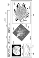
- the image processing unit 206 performs noise removal processing, particularly speckle noise processing, as the first preprocessing for performing the first blood vessel extraction processing (linear blood vessel extraction) on the OCT volume data 400D.
- noise removal processing particularly speckle noise processing
- Speckle noise processing includes Gaussian blur processing and the like.
- the image processing unit 206 performs the first blood vessel extraction processing (linear blood vessel extraction) on the OCT volume data 400D that has been subjected to the first preprocessing, thereby obtaining the OCT volume data 400D.
- a first choroidal blood vessel which is a linear portion, is extracted from the . Thereby, a first stereoscopic image is generated.
- a first blood vessel extraction process will be described.
- the image processing unit 206 performs image processing using, for example, an eigenvalue filter, a Gabor filter, or the like, and extracts a linear blood vessel region from the OCT volume data 400D.
- the blood vessel region is composed of low-luminance pixels (blackish pixels), and a region in which low-luminance pixels are continuous remains as the blood vessel portion.
- the image processing unit 206 performs image processing such as processing for deleting isolated regions that are not connected to surrounding blood vessels, median filtering, opening processing, contraction processing, etc. for the extracted linear blood vessel region. to remove noise regions.
- the image processing unit 206 performs binarization processing on the pixel data of the linear blood vessel region after the noise processing.
- the linear blood vessel shown in FIG. 9 is an example of the "first choroidal blood vessel” of the technology of the present disclosure
- the stereoscopic image 680L of the linear blood vessel is an example of the "first stereoscopic image” of the technology of the present disclosure. be.
- step 650 the image processing unit 206 performs binarization processing on the OCT volume data 400D as second preprocessing for performing the second blood vessel extraction processing (ampullary part extraction) on the OCT volume data 400D.
- the binarization threshold By setting the binarization threshold to a predetermined threshold value that leaves the enlarged blood vessel, the OCT volume data D has black pixels in the enlarged blood vessel and white pixels in the other portions.
- the image processing unit 206 extracts the second choroidal blood vessel, which is the ampulla, from the OCT volume data by deleting the noise region in the binarized OCT volume data 400D. Thereby, a second stereoscopic image is generated.
- the noise area may be an isolated area of black pixels or an area corresponding to a thin blood vessel.
- the image processing unit 206 performs median filtering, opening processing, contraction processing, or the like on the binarized OCT volume data 400D to remove noise regions.
- the image processing unit 206 further applies segmentation processing (such as dynamic contour, graph cut, or U-net image processing) may be applied.
- segmentation refers to image processing that performs binarization processing for separating the background and foreground of an image to be analyzed.
- the processing unit 208 saves the image data of the stereoscopic image 680B of the blood vessels in the ampulla in the RAM 266 .
- the blood vessel in the ampulla shown in FIG. 9 is an example of the "second choroidal blood vessel" of the technology of the present disclosure
- the stereoscopic image 680B of the blood vessel in the ampulla is the "second stereoscopic image” of the technology of the present disclosure. An example.
- Either one of the processing of steps 630 and 640 and the processing of steps 650 and 660 may be performed first, or may proceed simultaneously.
- step 670 the image processing unit 206 reads out from the RAM 266 the stereoscopic image 680L of linear blood vessels and the stereoscopic image 680B of the ampulla. Then, by aligning both stereoscopic images and calculating the logical sum of both images, the linear blood vessel stereoscopic image 680L and the ampulla stereoscopic image 680B are synthesized. As a result, a stereoscopic image 680M (see also FIG. 9) of choroidal blood vessels including vortex veins is generated.
- the image data of the stereoscopic image 680M is stored in the RAM 266 or the storage device 254 by the processing unit 208.
- the stereoscopic image 680M of the choroidal blood vessel including the vortex veins is an example of the "stereoscopic image of the choroidal blood vessel" of the technology of the present disclosure.
- a display screen for displaying a three-dimensional image (3D image) of the choroidal blood vessels including the generated vortex veins will be described below.
- the display screen is generated by the display control unit 204 of the server 140 based on the user's instruction, and output as an image signal to the viewer 150 by the processing unit 208 .
- the viewer 150 displays the display screen on the display based on the image signal.
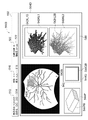
- a first display screen 500A is shown in FIG. As shown in Figure 10, the first display screen 500A has an information area 502 and an image display area 504A.
- the information area 502 has a patient ID display field 512, a patient name display field 514, an age display field 516, a visual acuity display field 518, a right/left eye display field 520, and an axial length display field 522.
- viewer 150 displays respective information based on the information received from server 140 .
- the image display area 504A is an area for displaying the image of the eye to be examined.
- the image display area 504A is provided with the following display fields. There is an image display field 548 .
- a comment field may be provided in the image display area 504A.
- the comment field is a remark column in which the user, an ophthalmologist, can arbitrarily enter observation results or diagnosis results.
- a UWF-SLO fundus image 542B obtained by photographing the fundus of the subject's eye with the ophthalmologic apparatus 110 is displayed.
- a range 542A indicating the position where the OCT volume data was acquired is superimposed on the UWF-SLO fundus image 542B. If there are multiple pieces of OCT volume data associated with the UWF-SLO image, multiple ranges may be superimposed and the user may select one position from the multiple ranges.
- FIG. 10 shows that the range including the upper right vortex vein of the UWF-SLO image was scanned.
- the OCT volume data conceptual diagram display field 544 displays an OCT volume data conceptual diagram (stereoscopic shape) 544B.
- OCT volume data conceptual diagram three-dimensional shape
- the user designates a section 544A to be displayed using a mouse or the like in order to display a section image in the depth direction.
- an enface image corresponding to the cross section 544A specified for the OCT volume data is generated and displayed in the tomographic image display field 546 as a tomographic image 546B.
- a stereoscopic image (3D image) 548B of the choroidal blood vessel obtained by image processing the OCT volume data is displayed.
- the stereoscopic image 548B can be rotated about three axes by user's operation.
- a cross section 548A is superimposed and displayed at a position corresponding to the cross section 544A of the displayed tomographic image 546B.
- a stereoscopic image of choroidal blood vessels can be recognized.
- the vortex veins and the surrounding choroidal blood vessels can be displayed as a stereoscopic image, enabling the user to obtain more information for diagnosis.
- the position of the OCT volume data on the UWF-SLO image can be grasped.
- the cross section of the stereoscopic image can be arbitrarily selected, and the user can obtain detailed information on the choroidal blood vessels by displaying the tomographic image.
- the choroidal blood vessels can be stereoscopically displayed without using OCT-A (OCT-angiography). It is possible to generate a stereoscopic image of choroidal blood vessels without performing complicated processing with a large amount of calculation, such as obtaining a motion contrast by taking a difference of OCT volume data.
- OCT-A requires a plurality of OCT volume data at different times to obtain the difference, but in the present embodiment, choroidal blood vessels are detected based on one OCT volume data without performing motion contrast extraction processing. 3D image can be generated.
- a second display screen 500B is shown in FIG. Since the second display screen 500B has the same fields as the fields of the first display screen 500A, the same fields are denoted by the same reference numerals and descriptions thereof are omitted, and different portions are described.
- the display screen 500B has an information area 502 and an image display area 504B. Since the image display area 504B has the same fields as the image display area 504A, the same fields are denoted by the same reference numerals and description thereof is omitted, and different portions are described. Specifically, the image display area 504B differs in that it has an en-face image display field 550 instead of the tomographic image display field 546 of the image display area 504A.
- the user specifies a section 544n to be displayed in order to display a section image (enface image) perpendicular to the depth direction.
- an en-face image 550B corresponding to cross-section 544n is generated based on the OCT volume data.
- the en-face image display field 550 displays an en-face image 550B corresponding to the cross section 544n.
- the en-face image 550B displayed in the en-face image display field 550 includes the contours 550A of the first and second blood vessels extracted in steps 640 and 660 of FIG. 6 in color (eg, red). Highlighting such as displaying may be performed.
- the position of the cross section 544n may be displayed numerically (in FIG. 11, the notation "nth layer").
- a slice 548n corresponding to the slice 544n is displayed superimposed on the stereoscopic image 548B.
- a stereoscopic (3D) image of the vortex vein at the selected vortex vein position can be recognized. Furthermore, the display screen 500B allows the perception of a stereoscopic image of the choroidal blood vessels. By scanning the area containing the vortex veins, the vortex veins and the surrounding choroidal blood vessels can be displayed as a stereoscopic image, enabling the user to obtain more information for diagnosis.
- the enface plane of the stereoscopic image can be arbitrarily selected, and the user can obtain detailed information regarding the depth direction of the choroidal blood vessels by displaying the enface image.
- a third display screen 500C is shown in FIG. Since the third display screen 500C has the same fields as the fields of the first display screen 500A, the same fields are denoted by the same reference numerals and descriptions thereof are omitted, and different portions are described.
- a third display screen 500C has an information area 502 and an image display area 504C. Since the image display area 504C has the same fields as the image display area 504A, the same fields are denoted by the same reference numerals and description thereof is omitted, and different portions are described.
- the image display area 504C differs from the display screens 500A and 500B in that it does not have the tomographic image display field 546 of the image display area 504A.
- the image display area 504C has two OCT volumes for recognizing OCT volume data from two different angles (first angle and second angle). It differs in that it has data conceptual diagram display fields 544P and 544Q.
- the OCT volume data conceptual diagram display field 544P displays a conceptual diagram 544PB showing the OCT volume data drawn at an angle of 45 degrees.
- the OCT volume data conceptual diagram display field 544Q displays a conceptual diagram 544QB showing the OCT volume data drawn as viewed from directly above.
- the OCT volume data conceptual diagram display fields 544P and 544Q can be designated at arbitrary angles by the user's operation.
- a choroidal blood vessel stereoscopic image display field 548 in the image display area 504C is for displaying choroidal blood vessel stereoscopic images 548D1B and 548D2B viewed from two different angles specified in the OCT volume data conceptual diagram display fields 544P and 544Q. 3D image sections 548D1, 548D2 of choroidal vessels.
- the two different angles may be preset directions or may be determined by AI. Note that the number is not limited to two, and may be three or more.
- the stereoscopic images 548D1B and 548D2B of the choroidal blood vessels may be moved in any direction selected by the user individually or in conjunction with each other, or may be clicked to be enlarged and displayed in another window.
- the image display area 504C of the third display screen 500C allows the user to check the stereoscopic image of the choroidal blood vessels from a plurality of different angles.
- the vortex veins can be confirmed at an angle as seen from the scleral side.
- a fourth display screen 500D is shown in FIG. Since the fourth display screen 500D has the same fields as the fields of the third display screen 500C, the same fields are denoted by the same reference numerals and descriptions thereof are omitted, and different portions are described.
- a fourth display screen 500D has an information area 502 and an image display area 504D. Since the image display area 504D has the same fields as the image display area 504C, the same fields are denoted by the same reference numerals and description thereof is omitted, and different portions will be described.
- FIG. 13 shows an example of synthesizing multiple OCT volume data and visualizing the choroidal blood vessels using the synthesized OCT volume data in order to visualize a wider range of choroidal blood vessels.
- the acquired ranges of two adjacent OCT volume data that partially overlap are displayed as ranges 542K and 542L superimposed on the UWF-SLO image 542B.
- the stereoscopic image display field 548 of the choroidal vessels in the image display area 504D has stereoscopic image display sections 548KL1 and 548KL2 for displaying stereoscopic images 548KL1B and 548KL2B obtained based on adjacent OCT volume data.
- the two stereoscopic images 548K1B and 548L1B of the choroidal blood vessels are stereoscopic images viewed from two different angles designated by the OCT volume data conceptual diagram display fields 544P and 544Q, as in FIG.
- a stereoscopic image of the choroidal blood vessels is created and displayed based on a plurality of adjacent OCT volume data. Therefore, a stereoscopic image of a wide range of choroidal blood vessels can be confirmed compared to a stereoscopic image of the choroidal blood vessels created based on one piece of OCT volume data.
- the user can confirm stereoscopic images of a wide range of choroidal blood vessels from a plurality of different angles. In particular, in a stereoscopic image of a choroidal blood vessel including vortex veins, the vortex veins can be confirmed at an angle as seen from the scleral side.
- a fifth display screen 500E is shown in FIG. Since the fifth display screen 500E has the same fields as the fields of the first display screen 500A, the same fields are denoted by the same reference numerals and descriptions thereof are omitted, and different portions are described.
- a fifth display screen 500E has an information area 502 and an image display area 504E. Since the image display area 504E has the same fields as the image display area 504A, the same fields are denoted by the same reference numerals and description thereof is omitted, and different portions will be described.
- the image display area 504E differs in that it does not have the tomographic image display field 544 and the tomographic image display field 546 of the image display area 504A. Further, the image display area 504E is different in that it has a stereoscopic image display field 548E of choroidal blood vessels suitable for follow-up, which will be described below, instead of the stereoscopic image display field 548 of the vortex veins of the image display area 504A.
- the choroidal blood vessel stereoscopic image display field 548E is a field for displaying a plurality of choroidal blood vessel stereoscopic images in chronological order using OCT volumes obtained by imaging the fundus of the same subject at different timings.
- the choroidal blood vessel stereoscopic image display field 548E has three stereoscopic image display sections 548E1, 548E2, and 548E3 in chronological order from the left of the photographing date of the fundus.
- Stereo image display sections 548E1, 548E2, 548E3 have photographing date display portions 548D1, 548D2, 548D3 that display the photographing date of the fundus.
- the stereoscopic image 548E1B obtained by photographing the fundus on March 12, 2021 is displayed in the stereoscopic image display section 548E1.
- a stereoscopic image 548E2B obtained by photographing the fundus on June 15, 2021 is displayed in the stereoscopic image display section 548E2.
- a stereoscopic image 548E3B obtained by photographing the fundus on September 12, 2021 is displayed in the stereoscopic image display section 548E3.
- the stereoscopic image display field 548E is not limited to three, and two or three or more stereoscopic images may be displayed.
- the choroidal blood vessel stereoscopic image display field 548E includes a return button 548R for giving an instruction to display a stereoscopic image photographed earlier than the currently displayed stereoscopic image of the vortex veins, and a return button 548R for giving an instruction to display a stereoscopic image photographed earlier than the currently displayed stereoscopic image. and a forward button 548F for giving an instruction to display a stereoscopic image with a newer date.
- the return button 548R is pressed, a stereoscopic image with an older shooting date than the currently displayed stereoscopic image is displayed.
- the forward button 548F is pressed, a stereoscopic image shot on a newer date than the currently displayed stereoscopic image is displayed.
- stereoscopic images of a plurality of choroidal blood vessels of the subject can be displayed in chronological order. Therefore, the user can confirm temporal changes in the thickness of the vortex vein, for example, and can confirm the appropriate treatment method required at the present time.
- a sixth display screen 500F is shown in FIG. As shown in Figure 15, the first display screen 500F has an information area 502F and an image display area 504F.
- the information area 502F has patient information display fields 502P, 502Q, and 502R that display information on a plurality of, for example, three patients.
- Each of the patient information display fields 502P, 502Q, 502R has a patient number display field, gender display field, age display field, right eye/left eye display field, vision display field, and disease name display field for the respective patient.
- a patient to be displayed can be specified by the user specifying a patient ID on a patient specifying screen (not shown). For example, it is possible to specify patients with the same disease, or patients with the same gender and annual interest rate.
- the display control unit 204 of the server 140 reads the stereoscopic image and UWF-SLO image corresponding to the designated patient ID, and generates the display screen 500F.
- Image display area 504F includes image display fields 548P, 548Q, 548R corresponding to each patient in information area 502F.
- the image display field 548P displays a patient number 542PA, a UWF-SLO image 542PB, and a stereoscopic image 548PB of choroidal blood vessels.
- FIG. 15 shows an example in which the patient number 542PA, the UWF-SLO image 542PB, and the stereoscopic image 548PB of the choroidal blood vessels are displayed in this order from the bottom of the page. It would be nice to be able to change the display position.
- an image display field 548P in addition to the patient number 542PA, the UWF-SLO image 542PB, and the stereoscopic image 548PB of the choroidal blood vessels, the attribute information of the patient that the user wants to compare and the fundus image of the same site (for example, around the optic papilla, (around the macula, etc.) may be displayed together.
- an image display field 548Q displays a patient number 542QA, a UWF-SLO image 542QB, and a stereoscopic image 548QB of choroidal blood vessels.
- a patient number 542RA, a UWF-SLO image 542RB, and a stereoscopic image 548RB of choroidal blood vessels are displayed in the image display field 548R.
- the information area 502F is not limited to displaying images of the eyes of three patients, and images of the eyes of two or more patients can be displayed.
- the sixth display screen 500F includes stereoscopic images of the choroidal vessels of each of a plurality of patients, the user can compare the stereoscopic images of the choroidal vessels of a plurality of patients without switching screens. .
- the first display screen 500A to the sixth display screen 500F may be selectively displayed individually or may be displayed in order.
- the choroidal blood vessels are extracted based on the OCT volume data including the choroid, and a stereoscopic image of the choroidal blood vessels is generated, so that the choroid can be stereoscopically visualized.
- a stereoscopic image of choroidal blood vessels is generated based on OCT volume data without using OCT-A (OCT-angiography). Therefore, in the present embodiment, it is possible to generate a three-dimensional image of the choroidal blood vessels without performing complicated processing with a large amount of calculation, such as taking the difference of the OCT volume data and extracting the motion contrast, thereby reducing the calculation amount. can be done.
- the image processing (FIG. 5) is executed by the server 140, but the technology of the present disclosure is not limited to this, and the ophthalmic apparatus 110, the viewer 150, or the additional It may be performed by the image processing device.
- each component may exist either singly or two or more.
- image processing may be performed only by a hardware configuration such as FPGA (Field-Programmable Gate Array) or ASIC (Application Specific Integrated Circuit).
- FPGA Field-Programmable Gate Array
- ASIC Application Specific Integrated Circuit
- the technology of the present disclosure includes the following technology, as it includes both cases in which image processing is realized by software configuration using a computer and cases in which it is not.
- An image processing device comprising:
- An acquisition unit (Second technology) an acquisition unit acquiring OCT volume data including the choroid; a generating unit extracting choroidal blood vessels based on the OCT volume data and generating a stereoscopic image of the choroidal blood vessels;
- An image processing method including The image processing unit 206 is an example of the “acquisition unit” and the “generation unit” of the technology of the present disclosure. The following technique is proposed from the above disclosure.
- a computer program product for image processing comprising:
- the computer program product comprises a computer readable storage medium that is not itself a transitory signal;
- the computer-readable storage medium stores a program, Said program to the computer, acquiring OCT volume data including the choroid; extracting choroidal blood vessels based on the OCT volume data and generating a stereoscopic image of the choroidal blood vessels; to run computer program product.
- Server 140 is an example of a “computer program product” of the technology of the present disclosure.
Landscapes
- Engineering & Computer Science (AREA)
- Physics & Mathematics (AREA)
- General Physics & Mathematics (AREA)
- Computer Graphics (AREA)
- Theoretical Computer Science (AREA)
- Software Systems (AREA)
- Life Sciences & Earth Sciences (AREA)
- Health & Medical Sciences (AREA)
- General Engineering & Computer Science (AREA)
- Geometry (AREA)
- Computer Hardware Design (AREA)
- Medical Informatics (AREA)
- Ophthalmology & Optometry (AREA)
- Biomedical Technology (AREA)
- Heart & Thoracic Surgery (AREA)
- Biophysics (AREA)
- Molecular Biology (AREA)
- Surgery (AREA)
- Animal Behavior & Ethology (AREA)
- General Health & Medical Sciences (AREA)
- Public Health (AREA)
- Veterinary Medicine (AREA)
- Eye Examination Apparatus (AREA)
Abstract
Description
RPE層400Rより深い所定範囲の領域の脈絡膜の領域は、本開示の技術の「脈絡膜部分」の一例である。
図9に示す線状血管は、本開示の技術の「第1の脈絡膜血管」の一例であり、線状血管の立体画像680Lは、本開示の技術の「第1の立体画像」の一例である。
図9に示す膨大部の血管は、本開示の技術の「第2の脈絡膜血管」の一例であり、膨大部の血管の立体画像680Bは、本開示の技術の「第2の立体画像」の一例である。
渦静脈を含む脈絡膜血管の立体画像680Mは、本開示の技術の「脈絡膜血管の立体画像」の一例である。
同様に、画像表示フィールド548Qには、患者番号542QA、UWF-SLO画像542QB、及び脈絡膜血管の立体画像548QBが表示される。画像表示フィールド548Rには、患者番号542RA、UWF-SLO画像542RB、及び脈絡膜血管の立体画像548RBが表示される。
なお、インフォメーションエリア502Fには3人の患者の被検眼の画像に限らず、2人や3人以上の被検眼の画像を表示することができる。
脈絡膜を含むOCTボリュームデータを取得する取得部と、
前記OCTボリュームデータに基づいて脈絡膜血管を抽出し、前記脈絡膜血管の立体画像を生成する生成部と、
を備える画像処理装置。
取得部が、脈絡膜を含むOCTボリュームデータを取得するステップと、
生成部が、前記OCTボリュームデータに基づいて脈絡膜血管を抽出し、前記脈絡膜血管の立体画像を生成するステップと、
を含む画像処理方法。
画像処理部206は、本開示の技術の「取得部」及び「生成部」の一例である。
以上の開示内容から以下の技術が提案される。
画像処理するためのコンピュータープログラム製品であって、
前記コンピュータープログラム製品は、それ自体が一時的な信号ではないコンピュータ可読記憶媒体を備え、
前記コンピュータ可読記憶媒体には、プログラムが格納されており、
前記プログラムは、
コンピュータに、
脈絡膜を含むOCTボリュームデータを取得するステップと、
前記OCTボリュームデータに基づいて脈絡膜血管を抽出し、前記脈絡膜血管の立体画像を生成するステップと、
を実行させる、
コンピュータープログラム製品。
サーバ140は、本開示の技術の「コンピュータープログラム製品」の一例である。
Claims (6)
- プロセッサが行う画像処理方法であって、
脈絡膜を含むOCTボリュームデータを取得するステップと、
前記OCTボリュームデータに基づいて脈絡膜血管を抽出し、前記脈絡膜血管の立体画像を生成するステップと、
を含む、画像処理方法。 - 前記OCTボリュームデータは、眼底の少なくとも渦静脈を含む領域をスキャンして得られることを特徴とする、請求項1に記載の画像処理方法。
- 前記脈絡膜血管の立体画像を生成するステップは、
前記OCTボリュームデータから線状部である第1の脈絡膜血管を抽出することにより、第1の立体画像を生成するステップと、
前記OCTボリュームデータから膨大部である第2の脈絡膜血管を抽出することにより、第2の立体画像を生成するステップと、
前記第1の立体画像と前記第2の立体画像を合成することにより、前記脈絡膜血管の立体画像を生成するステップと、
含む、請求項1または請求項2に記載の画像処理方法。 - 前記OCTボリュームデータから前記脈絡膜部分の脈絡膜OCTボリュームデータを抽出するステップをさらに有し、
前記立体画像を生成するステップは、前記脈絡膜OCTボリュームデータに基づいて前記立体画像を生成する、ことを特徴とする請求項1ないし3に記載の画像処理方法。 - メモリと、前記メモリに接続するプロセッサとを備え、
前記プロセッサは、
脈絡膜を含むOCTボリュームデータを取得するステップと、
前記OCTボリュームデータに基づいて脈絡膜血管を抽出し、前記脈絡膜血管の立体画像を生成するステップと、
を実行する、画像処理装置。 - コンピュータに、
脈絡膜を含むOCTボリュームデータを取得するステップと、
前記OCTボリュームデータに基づいて脈絡膜血管を抽出し、前記脈絡膜血管の立体画像を生成するステップと、
を実行させるプログラム。
Priority Applications (2)
| Application Number | Priority Date | Filing Date | Title |
|---|---|---|---|
| US18/278,128 US20240153203A1 (en) | 2021-02-22 | 2022-02-22 | Image processing method, image processing device, and program |
| JP2023500975A JPWO2022177028A1 (ja) | 2021-02-22 | 2022-02-22 |
Applications Claiming Priority (2)
| Application Number | Priority Date | Filing Date | Title |
|---|---|---|---|
| JP2021-026196 | 2021-02-22 | ||
| JP2021026196 | 2021-02-22 |
Publications (1)
| Publication Number | Publication Date |
|---|---|
| WO2022177028A1 true WO2022177028A1 (ja) | 2022-08-25 |
Family
ID=82932269
Family Applications (1)
| Application Number | Title | Priority Date | Filing Date |
|---|---|---|---|
| PCT/JP2022/007393 WO2022177028A1 (ja) | 2021-02-22 | 2022-02-22 | 画像処理方法、画像処理装置、及びプログラム |
Country Status (3)
| Country | Link |
|---|---|
| US (1) | US20240153203A1 (ja) |
| JP (1) | JPWO2022177028A1 (ja) |
| WO (1) | WO2022177028A1 (ja) |
Citations (8)
| Publication number | Priority date | Publication date | Assignee | Title |
|---|---|---|---|---|
| JP2012071043A (ja) * | 2010-09-29 | 2012-04-12 | Canon Inc | 情報処理装置、その表示処理方法及びプログラム |
| JP2015000131A (ja) * | 2013-06-13 | 2015-01-05 | 国立大学法人 筑波大学 | 脈絡膜の血管網を選択的に可視化し解析する光干渉断層計装置及びその画像処理プログラム |
| CN108416793A (zh) * | 2018-01-16 | 2018-08-17 | 武汉诺影云科技有限公司 | 基于三维相干断层成像图像的脉络膜血管分割方法及系统 |
| WO2019203309A1 (ja) * | 2018-04-18 | 2019-10-24 | 株式会社ニコン | 画像処理方法、プログラム、画像処理装置、及び眼科システム |
| JP2020058627A (ja) * | 2018-10-10 | 2020-04-16 | 株式会社ニコン | 画像処理方法、画像処理装置、画像処理プログラム、及び血管径算出装置 |
| JP2020058647A (ja) * | 2018-10-11 | 2020-04-16 | 株式会社ニコン | 画像処理方法、画像処理装置、及び画像処理プログラム |
| JP2021167802A (ja) * | 2020-04-10 | 2021-10-21 | 株式会社トプコン | 光コヒーレンストモグラフィ画像を用いた3次元解析 |
| JP2021168759A (ja) * | 2020-04-14 | 2021-10-28 | 株式会社ニコン | 画像処理方法、画像処理装置、及び画像処理プログラム |
-
2022
- 2022-02-22 WO PCT/JP2022/007393 patent/WO2022177028A1/ja active Application Filing
- 2022-02-22 US US18/278,128 patent/US20240153203A1/en active Pending
- 2022-02-22 JP JP2023500975A patent/JPWO2022177028A1/ja active Pending
Patent Citations (8)
| Publication number | Priority date | Publication date | Assignee | Title |
|---|---|---|---|---|
| JP2012071043A (ja) * | 2010-09-29 | 2012-04-12 | Canon Inc | 情報処理装置、その表示処理方法及びプログラム |
| JP2015000131A (ja) * | 2013-06-13 | 2015-01-05 | 国立大学法人 筑波大学 | 脈絡膜の血管網を選択的に可視化し解析する光干渉断層計装置及びその画像処理プログラム |
| CN108416793A (zh) * | 2018-01-16 | 2018-08-17 | 武汉诺影云科技有限公司 | 基于三维相干断层成像图像的脉络膜血管分割方法及系统 |
| WO2019203309A1 (ja) * | 2018-04-18 | 2019-10-24 | 株式会社ニコン | 画像処理方法、プログラム、画像処理装置、及び眼科システム |
| JP2020058627A (ja) * | 2018-10-10 | 2020-04-16 | 株式会社ニコン | 画像処理方法、画像処理装置、画像処理プログラム、及び血管径算出装置 |
| JP2020058647A (ja) * | 2018-10-11 | 2020-04-16 | 株式会社ニコン | 画像処理方法、画像処理装置、及び画像処理プログラム |
| JP2021167802A (ja) * | 2020-04-10 | 2021-10-21 | 株式会社トプコン | 光コヒーレンストモグラフィ画像を用いた3次元解析 |
| JP2021168759A (ja) * | 2020-04-14 | 2021-10-28 | 株式会社ニコン | 画像処理方法、画像処理装置、及び画像処理プログラム |
Also Published As
| Publication number | Publication date |
|---|---|
| JPWO2022177028A1 (ja) | 2022-08-25 |
| US20240153203A1 (en) | 2024-05-09 |
Similar Documents
| Publication | Publication Date | Title |
|---|---|---|
| US10561311B2 (en) | Ophthalmic imaging apparatus and ophthalmic information processing apparatus | |
| JP2023009530A (ja) | 画像処理方法、画像処理装置、及びプログラム | |
| JP7441783B2 (ja) | 画像処理方法、プログラム、眼科装置、及び脈絡膜血管画像生成方法 | |
| JP2022040372A (ja) | 眼科装置 | |
| JP7134324B2 (ja) | 眼科撮影装置、その制御方法、プログラム、及び記録媒体 | |
| JP2022109721A (ja) | 画像処理方法、画像処理装置、及びプログラム | |
| JP2024105697A (ja) | 画像処理方法、画像処理装置、及び画像処理プログラム | |
| WO2021074960A1 (ja) | 画像処理方法、画像処理装置、及び画像処理プログラム | |
| JP6736734B2 (ja) | 眼科撮影装置及び眼科情報処理装置 | |
| JP2023030184A (ja) | 画像処理方法、プログラム、画像処理装置、及び眼科システム | |
| WO2022177028A1 (ja) | 画像処理方法、画像処理装置、及びプログラム | |
| JP7419946B2 (ja) | 画像処理方法、画像処理装置、及び画像処理プログラム | |
| JP7286283B2 (ja) | 眼科装置 | |
| JP2022089086A (ja) | 画像処理方法、画像処理装置、及び画像処理プログラム | |
| WO2023199847A1 (ja) | 画像処理方法、画像処理装置、及びプログラム | |
| WO2022181729A1 (ja) | 画像処理方法、画像処理装置、及び画像処理プログラム | |
| JP7306482B2 (ja) | 画像処理方法、画像処理装置、及びプログラム | |
| WO2023282339A1 (ja) | 画像処理方法、画像処理プログラム、画像処理装置及び眼科装置 | |
| WO2023199848A1 (ja) | 画像処理方法、画像処理装置、及びプログラム | |
| JP7272453B2 (ja) | 画像処理方法、画像処理装置、およびプログラム | |
| WO2022113409A1 (ja) | 画像処理方法、画像処理装置、及びプログラム | |
| WO2021210295A1 (ja) | 画像処理方法、画像処理装置、及びプログラム | |
| JP7416083B2 (ja) | 画像処理方法、画像処理装置、およびプログラム | |
| WO2021210281A1 (ja) | 画像処理方法、画像処理装置、及び画像処理プログラム | |
| JP2023066198A (ja) | 情報出力装置、眼底画像撮影装置、情報出力方法、及び情報出力プログラム |
Legal Events
| Date | Code | Title | Description |
|---|---|---|---|
| 121 | Ep: the epo has been informed by wipo that ep was designated in this application |
Ref document number: 22756345 Country of ref document: EP Kind code of ref document: A1 |
|
| WWE | Wipo information: entry into national phase |
Ref document number: 18278128 Country of ref document: US |
|
| WWE | Wipo information: entry into national phase |
Ref document number: 2023500975 Country of ref document: JP |
|
| NENP | Non-entry into the national phase |
Ref country code: DE |
|
| 122 | Ep: pct application non-entry in european phase |
Ref document number: 22756345 Country of ref document: EP Kind code of ref document: A1 |