WO2022176813A1 - 学習装置、学習方法、学習装置の作動プログラム、教師データ生成装置、機械学習モデル及び医療用撮影装置 - Google Patents
学習装置、学習方法、学習装置の作動プログラム、教師データ生成装置、機械学習モデル及び医療用撮影装置 Download PDFInfo
- Publication number
- WO2022176813A1 WO2022176813A1 PCT/JP2022/005744 JP2022005744W WO2022176813A1 WO 2022176813 A1 WO2022176813 A1 WO 2022176813A1 JP 2022005744 W JP2022005744 W JP 2022005744W WO 2022176813 A1 WO2022176813 A1 WO 2022176813A1
- Authority
- WO
- WIPO (PCT)
- Prior art keywords
- imaging
- learning
- human body
- image
- model
- Prior art date
- Legal status (The legal status is an assumption and is not a legal conclusion. Google has not performed a legal analysis and makes no representation as to the accuracy of the status listed.)
- Ceased
Links
Images







Classifications
-
- G—PHYSICS
- G06—COMPUTING OR CALCULATING; COUNTING
- G06T—IMAGE DATA PROCESSING OR GENERATION, IN GENERAL
- G06T7/00—Image analysis
- G06T7/0002—Inspection of images, e.g. flaw detection
-
- G—PHYSICS
- G06—COMPUTING OR CALCULATING; COUNTING
- G06T—IMAGE DATA PROCESSING OR GENERATION, IN GENERAL
- G06T7/00—Image analysis
- G06T7/0002—Inspection of images, e.g. flaw detection
- G06T7/0012—Biomedical image inspection
-
- A—HUMAN NECESSITIES
- A61—MEDICAL OR VETERINARY SCIENCE; HYGIENE
- A61B—DIAGNOSIS; SURGERY; IDENTIFICATION
- A61B5/00—Measuring for diagnostic purposes; Identification of persons
- A61B5/103—Measuring devices for testing the shape, pattern, colour, size or movement of the body or parts thereof, for diagnostic purposes
- A61B5/107—Measuring physical dimensions, e.g. size of the entire body or parts thereof
-
- A—HUMAN NECESSITIES
- A61—MEDICAL OR VETERINARY SCIENCE; HYGIENE
- A61B—DIAGNOSIS; SURGERY; IDENTIFICATION
- A61B6/00—Apparatus or devices for radiation diagnosis; Apparatus or devices for radiation diagnosis combined with radiation therapy equipment
-
- A—HUMAN NECESSITIES
- A61—MEDICAL OR VETERINARY SCIENCE; HYGIENE
- A61B—DIAGNOSIS; SURGERY; IDENTIFICATION
- A61B6/00—Apparatus or devices for radiation diagnosis; Apparatus or devices for radiation diagnosis combined with radiation therapy equipment
- A61B6/08—Auxiliary means for directing the radiation beam to a particular spot, e.g. using light beams
-
- A—HUMAN NECESSITIES
- A61—MEDICAL OR VETERINARY SCIENCE; HYGIENE
- A61B—DIAGNOSIS; SURGERY; IDENTIFICATION
- A61B8/00—Diagnosis using ultrasonic, sonic or infrasonic waves
- A61B8/13—Tomography
- A61B8/14—Echo-tomography
-
- G—PHYSICS
- G06—COMPUTING OR CALCULATING; COUNTING
- G06N—COMPUTING ARRANGEMENTS BASED ON SPECIFIC COMPUTATIONAL MODELS
- G06N20/00—Machine learning
-
- G—PHYSICS
- G06—COMPUTING OR CALCULATING; COUNTING
- G06N—COMPUTING ARRANGEMENTS BASED ON SPECIFIC COMPUTATIONAL MODELS
- G06N3/00—Computing arrangements based on biological models
- G06N3/02—Neural networks
- G06N3/04—Architecture, e.g. interconnection topology
- G06N3/0464—Convolutional networks [CNN, ConvNet]
-
- G—PHYSICS
- G06—COMPUTING OR CALCULATING; COUNTING
- G06N—COMPUTING ARRANGEMENTS BASED ON SPECIFIC COMPUTATIONAL MODELS
- G06N3/00—Computing arrangements based on biological models
- G06N3/02—Neural networks
- G06N3/08—Learning methods
-
- G—PHYSICS
- G06—COMPUTING OR CALCULATING; COUNTING
- G06N—COMPUTING ARRANGEMENTS BASED ON SPECIFIC COMPUTATIONAL MODELS
- G06N3/00—Computing arrangements based on biological models
- G06N3/02—Neural networks
- G06N3/08—Learning methods
- G06N3/09—Supervised learning
-
- G—PHYSICS
- G06—COMPUTING OR CALCULATING; COUNTING
- G06T—IMAGE DATA PROCESSING OR GENERATION, IN GENERAL
- G06T19/00—Manipulating three-dimensional [3D] models or images for computer graphics
-
- G—PHYSICS
- G06—COMPUTING OR CALCULATING; COUNTING
- G06T—IMAGE DATA PROCESSING OR GENERATION, IN GENERAL
- G06T2207/00—Indexing scheme for image analysis or image enhancement
- G06T2207/10—Image acquisition modality
- G06T2207/10116—X-ray image
-
- G—PHYSICS
- G06—COMPUTING OR CALCULATING; COUNTING
- G06T—IMAGE DATA PROCESSING OR GENERATION, IN GENERAL
- G06T2207/00—Indexing scheme for image analysis or image enhancement
- G06T2207/10—Image acquisition modality
- G06T2207/10132—Ultrasound image
-
- G—PHYSICS
- G06—COMPUTING OR CALCULATING; COUNTING
- G06T—IMAGE DATA PROCESSING OR GENERATION, IN GENERAL
- G06T2207/00—Indexing scheme for image analysis or image enhancement
- G06T2207/20—Special algorithmic details
- G06T2207/20081—Training; Learning
-
- G—PHYSICS
- G06—COMPUTING OR CALCULATING; COUNTING
- G06T—IMAGE DATA PROCESSING OR GENERATION, IN GENERAL
- G06T2207/00—Indexing scheme for image analysis or image enhancement
- G06T2207/20—Special algorithmic details
- G06T2207/20084—Artificial neural networks [ANN]
-
- G—PHYSICS
- G16—INFORMATION AND COMMUNICATION TECHNOLOGY [ICT] SPECIALLY ADAPTED FOR SPECIFIC APPLICATION FIELDS
- G16H—HEALTHCARE INFORMATICS, i.e. INFORMATION AND COMMUNICATION TECHNOLOGY [ICT] SPECIALLY ADAPTED FOR THE HANDLING OR PROCESSING OF MEDICAL OR HEALTHCARE DATA
- G16H30/00—ICT specially adapted for the handling or processing of medical images
-
- G—PHYSICS
- G16—INFORMATION AND COMMUNICATION TECHNOLOGY [ICT] SPECIALLY ADAPTED FOR SPECIFIC APPLICATION FIELDS
- G16H—HEALTHCARE INFORMATICS, i.e. INFORMATION AND COMMUNICATION TECHNOLOGY [ICT] SPECIALLY ADAPTED FOR THE HANDLING OR PROCESSING OF MEDICAL OR HEALTHCARE DATA
- G16H50/00—ICT specially adapted for medical diagnosis, medical simulation or medical data mining; ICT specially adapted for detecting, monitoring or modelling epidemics or pandemics
- G16H50/20—ICT specially adapted for medical diagnosis, medical simulation or medical data mining; ICT specially adapted for detecting, monitoring or modelling epidemics or pandemics for computer-aided diagnosis, e.g. based on medical expert systems
-
- G—PHYSICS
- G16—INFORMATION AND COMMUNICATION TECHNOLOGY [ICT] SPECIALLY ADAPTED FOR SPECIFIC APPLICATION FIELDS
- G16H—HEALTHCARE INFORMATICS, i.e. INFORMATION AND COMMUNICATION TECHNOLOGY [ICT] SPECIALLY ADAPTED FOR THE HANDLING OR PROCESSING OF MEDICAL OR HEALTHCARE DATA
- G16H50/00—ICT specially adapted for medical diagnosis, medical simulation or medical data mining; ICT specially adapted for detecting, monitoring or modelling epidemics or pandemics
- G16H50/30—ICT specially adapted for medical diagnosis, medical simulation or medical data mining; ICT specially adapted for detecting, monitoring or modelling epidemics or pandemics for calculating health indices; for individual health risk assessment
-
- G—PHYSICS
- G16—INFORMATION AND COMMUNICATION TECHNOLOGY [ICT] SPECIALLY ADAPTED FOR SPECIFIC APPLICATION FIELDS
- G16H—HEALTHCARE INFORMATICS, i.e. INFORMATION AND COMMUNICATION TECHNOLOGY [ICT] SPECIALLY ADAPTED FOR THE HANDLING OR PROCESSING OF MEDICAL OR HEALTHCARE DATA
- G16H50/00—ICT specially adapted for medical diagnosis, medical simulation or medical data mining; ICT specially adapted for detecting, monitoring or modelling epidemics or pandemics
- G16H50/70—ICT specially adapted for medical diagnosis, medical simulation or medical data mining; ICT specially adapted for detecting, monitoring or modelling epidemics or pandemics for mining of medical data, e.g. analysing previous cases of other patients
Definitions
- the technology of the present disclosure relates to a learning device, a learning method, a learning device operating program, a teacher data generation device, a machine learning model, and a medical imaging device.
- a radiation imaging device is known as a medical imaging device.
- the technician performs positioning to adjust the relative positional relationship between the radiation imaging apparatus and the subject based on the imaging order obtained by the doctor who requested the imaging (for example, JP-A-2020-2020). -192440).
- the imaging order the imaging region such as chest or abdomen and the imaging direction such as front or back are defined.
- the technician positions the subject based on the content of the radiographing order.
- camera images such as those described above to confirm whether the subject's imaging region and imaging direction conform to the content of the imaging order.
- a camera image it is being studied to use a camera image as an input and derive a photographed part and photographing direction of a subject in the camera image to a machine learning model. According to this, it is possible to prevent a mistake such as imaging an imaging part different from the imaging part specified in the imaging order.
- the subject who is the subject, often has limited freedom of movement, and the burden of retaking the image may be large. high. Therefore, when such a machine learning model is used in medical imaging, a machine learning model with high recognition accuracy of the imaging region and imaging direction of the subject in the camera image is desired.
- the recognition accuracy of the machine learning model is improved as the camera images of the teacher data are more diverse for each combination of imaging parts and imaging directions.
- the recognition accuracy of the machine learning model is improved as the camera images of the teacher data are more diverse for each combination of imaging parts and imaging directions.
- the machine learning model needs to recognize the combination of the same imaging region and imaging direction. For this reason, it is necessary to collect a large number of various camera images in which the subject's posture and appearance are different for each combination of imaging region and imaging direction, as camera images to be used as training data.
- the technology according to the present disclosure makes it possible to efficiently learn a machine learning model for deriving the imaging part and imaging direction of the subject in the camera image, compared to using only the camera image as teacher data.
- a learning device, a learning method, a learning program, a training data generation device, and a machine learning model are provided.
- the learning device of the present disclosure receives as an input a camera image obtained by photographing a subject positioned with respect to a medical imaging apparatus with an optical camera.
- a learning device for learning a machine learning model for deriving an imaging part and imaging direction comprising a processor and a memory connected to or built into the processor, the processor being a human body configured by three-dimensional computer graphics data. generating a plurality of pseudo images of the human body generated based on the model and simulating a subject positioned with respect to a medical imaging device for each combination of imaging regions and imaging directions;
- a machine learning model is learned using a plurality of teacher data composed of generated pseudo images and combined correct data.
- the three-dimensional computer graphics data may be accompanied by modeling parameters for changing at least one of the posture and appearance of the human body model.
- the modeling parameters may include at least one of physique information representing the physique of the human body model, gender, posture information, skin color, hair color, hairstyle, and clothing.
- the processor can generate a pseudo image by rendering the human body model from a set viewpoint, and the viewpoint may be changeable by rendering parameters.
- the viewpoint information for setting the viewpoint may include the focal length of the virtual camera virtually installed at the viewpoint and the shooting distance, which is the distance from the virtual camera to the human body model.
- the processor When training data composed of a pseudo image and correct data is used as first training data, the processor generates second training data composed of a camera image captured by an optical camera and correct data in addition to the first training data.
- a machine learning model may be trained using teacher data.
- physique information representing the physique of the subject is derived using camera images as input.
- a machine learning model for output may be trained.
- the medical imaging device may include at least one of a radiographic imaging device and an ultrasonic imaging device.
- a camera image obtained by photographing a subject positioned with respect to a medical imaging apparatus with an optical camera is used as an input, and the photographed part and photographing direction of the subject appearing in the camera image are derived.
- a learning method for learning a machine learning model using a computer which is a pseudo image of a human body generated based on a human body model composed of three-dimensional computer graphics data, for medical imaging equipment
- a plurality of pseudo-images simulating the subject positioned in the position of the subject are generated for each combination of imaging parts and imaging directions, and a plurality of training data composed of the generated pseudo-images and the correct data of the combinations are generated. to train a machine learning model.
- the operating program of the learning device receives as input a camera image obtained by photographing a subject positioned with respect to a medical imaging apparatus with an optical camera, and derives the photographed part and photographing direction of the subject in the camera image.
- An operating program for a learning device that causes a computer to function as a learning device for learning a machine learning model, and is a pseudo image of a human body generated based on a human body model composed of three-dimensional computer graphics data, A plurality of pseudo images simulating a subject positioned with respect to a medical imaging apparatus are generated for each combination of imaging regions and imaging directions, and the generated pseudo images and correct data for the combinations are composed.
- a program for operating a learning device that causes a computer to function as a learning device that trains a machine learning model using a plurality of teacher data.
- the training data generation device of the present disclosure receives as input a camera image obtained by photographing a subject positioned with respect to a medical imaging device with an optical camera, and determines the imaging region and imaging direction of the subject in the camera image.
- a teacher data generation device for generating teacher data used for learning a machine learning model to be derived comprising a processor and a memory connected to or built into the processor, the processor for generating a pseudo image of the human body
- the three-dimensional computer graphics data that constitutes the human body model of the, using the three-dimensional computer graphics data accompanied by parameters for changing at least one of the posture and appearance of the human body model, the parameters is changed to generate a plurality of pseudo images in which at least one of the posture and appearance of the human body model is different for each combination of the photographing part and the photographing direction, and the plurality of pseudo images generated and the correct data for the combination are composed.
- the machine learning model of the present disclosure uses as input a camera image of a subject positioned with respect to a medical imaging device, which is captured by an optical camera, and derives the imaging region and imaging direction of the subject in the camera image.
- a machine learning model that is a pseudo image of a human body generated based on a human body model composed of three-dimensional computer graphics data, and a subject positioned with respect to a medical imaging device and correct data for combinations of imaging parts and imaging directions, and learning is performed using a plurality of teacher data generated for each combination.
- the medical imaging device of the present disclosure is equipped with a machine learning model.
- FIG. 4 is a diagram for explaining functions of a console; It is a figure explaining a learned model. It is a figure which shows the hardware constitutions of a learning apparatus. It is a figure explaining the function of a learning apparatus.
- FIG. 4 is a diagram showing an example of 3DCG data;
- FIG. 4 is a diagram showing functions of a teacher data generation unit;
- FIG. 4 is a diagram showing an example of a pseudo image;
- FIG. 4 is a diagram showing an example of a pseudo image;
- FIG. 4 is a diagram showing an example of a pseudo image;
- FIG. 4 is a diagram showing an example of a pseudo image;
- FIG. 4 is a diagram showing an example of a pseudo image;
- FIG. 4 is a diagram showing an example of a pseudo image;
- FIG. 4 is a diagram showing an example of a pseudo image;
- FIG. 4 is a diagram showing an example of a pseudo image;
- FIG. 4 is a diagram showing an example of a pseudo
- FIG. 4 is a diagram showing an example of a pseudo image
- FIG. 4 is a diagram showing an example of a pseudo image
- FIG. 4 is a diagram showing an example of a pseudo image
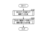
- 4 is a main flow chart showing a processing procedure of the learning device
- 4 is a flow chart showing a teaching data generation procedure
- It is a flow chart which shows a learning procedure.
- FIG. 10 is a diagram showing a modified example in which pseudo images and camera images are mixed as training data; It is a figure which shows the modification which added the collation part. It is a figure explaining the learned model for a physique output.
- FIG. 4 is a diagram for explaining teacher data used for learning a machine learning model for outputting physique. It is a figure explaining the teacher data production
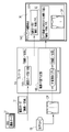
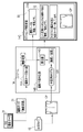
- FIG. 1 is a diagram showing an outline of the overall configuration of the learning device 40 and the radiation imaging system 10 of the present disclosure.
- the radiation imaging system 10 is an example of a medical imaging apparatus according to the technology of the present disclosure, and an example of a radiation imaging apparatus.
- the radiation imaging system 10 obtains a radiation image XP of the subject H by imaging the subject H using the radiation R.
- FIG. When radiography is performed using the radiography system 10 , a radiological technologist (hereinafter simply referred to as a radiographer) RG who is an operator positions the subject H with respect to the radiography system 10 .
- a radiological technologist hereinafter simply referred to as a radiographer
- the radiation imaging system 10 of this example has an imaging support function that assists the technician RG in checking whether the subject H is properly positioned according to the imaging order 31 .
- the shooting support function is performed using a learned model LM generated by learning the machine learning model LM0.
- the learning device 40 has a learning section 52 for learning the machine learning model LM0.
- the learning unit 52 is used to learn the machine learning model LM0 in order to generate a trained model LM provided to the radiography system 10.
- the trained model LM is also a machine learning model, it is distinguished from the machine learning model LM0 to be learned by the learning device 40 for the sake of convenience.
- a machine learning model that is put into operation is called a trained model LM.
- the machine learning model LM0 may be an unlearned machine learning model, or may be a trained model LM that is subject to additional learning.
- the learning device 40 will be described.
- the radiation imaging system 10 includes a radiation source 11, a radiation source control device 12, an electronic cassette 13, and a console 14.
- the electronic cassette 13 is an example of a radiographic image detector that detects a radiographic image XP of the subject H by receiving radiation R transmitted through the subject H, and is a portable radiographic image detector.
- the radiation imaging system 10 of this example has an optical camera 15 .
- the optical camera 15 is configured to realize the imaging support function described above, and is used to photograph the state of the subject H positioned with respect to the radiation imaging system 10 .
- Positioning when radiography is performed is the work of adjusting the relative positions of the subject H, the electronic cassette 13, and the radiation source 11, and is performed as follows, for example.
- the technician RG first aligns the position of the electronic cassette 13 with the body part of the subject H to be imaged.
- the electronic cassette 13 is arranged facing the subject H's chest.
- the position of the radiation source 11 is adjusted so that the electronic cassette 13 positioned at the imaging site of the subject H faces the radiation source 11 .
- the radiation source 11 faces the back of the chest of the subject H, and the back of the subject H is the imaging direction in which the radiation R is emitted.
- the technician RG When imaging the chest from the front, the technician RG makes the front of the chest of the subject H face the radiation source 11 . By performing such positioning and irradiating the radiation R from the back of the subject H, a radiographic image XP of the chest of the subject H can be captured.
- the electronic cassette 13 is set on a standing imaging table 25 for imaging the subject H in an upright position.
- the electronic cassette 13 may be set on a supine imaging table or the like for imaging the subject H in the supine position. Further, since the electronic cassette 13 is portable, it can be removed from the imaging table and used alone.
- the radiation source 11 includes a radiation tube 11A that generates radiation R, and an irradiation field limiter 11B that limits the irradiation field, which is the area where the radiation R is irradiated.
- the radiation tube 11A has, for example, a filament that emits thermoelectrons and a target that emits radiation upon collision with the thermoelectrons emitted from the filament.
- the irradiation field limiter 11B has, for example, four lead plates for shielding the radiation R arranged on each side of a quadrangle, thereby forming a quadrangular irradiation opening through which the radiation R is transmitted in the center.
- the size of the irradiation aperture is changed by moving the position of the lead plate. This adjusts the size of the irradiation field.
- the radiation source 11 may incorporate an irradiation field display light source (not shown) for visualizing the irradiation field by projecting visible light onto the subject H through the irradiation aperture. good.
- the radiation source 11 is of a ceiling-suspended type in the example of FIG.
- the vertical height of the radiation source 11 can be adjusted by extending and contracting the support 22 .
- the column 22 is attached to a ceiling running device (not shown) that runs on rails arranged on the ceiling, and can move horizontally along the rails.
- the radiation source 11 can rotate around the focal point of the radiation tube 11A.
- the radiation source 11 can adjust the irradiation direction of the radiation R by such various displacement mechanisms.
- the radiation source control device 12 controls the radiation source 11 .
- the radiation source control device 12 is provided with an operation panel (not shown).
- the radiation irradiation conditions and the size of the irradiation aperture of the irradiation field limiter 11B are set by the operator RG operating the operation panel.
- Radiation irradiation conditions include a tube voltage (unit: kv) applied to the radiation source 11, a tube current (unit: mA), and a radiation irradiation time (unit: mS).
- the radiation source control device 12 has a voltage generator that generates a voltage to be applied to the radiation tube 11A, and a timer.
- the radiation source control device 12 operates the radiation source 11 so as to generate the radiation R according to the irradiation conditions by controlling the voltage generator and the timer.
- An irradiation switch 16 is connected to the radiation source control device 12 via a cable or the like.
- the irradiation switch 16 is operated by the technician RG when starting radiation irradiation.
- the radiation source control device 12 causes the radiation tube 11A to emit radiation. Thereby, the radiation R is irradiated toward the irradiation field.
- the electronic cassette 13 detects the radiation image XP based on the radiation R emitted from the radiation source 11 and transmitted through the imaging region of the subject H, as described above.
- the electronic cassette 13 has, for example, a wireless communication unit and a battery, and can operate wirelessly.
- the electronic cassette 13 wirelessly transmits the detected radiation image XP to the console 14 .
- the optical camera 15 is an optical digital camera including a CMOS (Complementary Metal Oxide Semiconductor) type image sensor or a CCD (Charge Coupled Device) type image sensor.
- CMOS Complementary Metal Oxide Semiconductor
- CCD Charge Coupled Device
- the optical camera 15 is capable of still image shooting and moving image shooting.
- the optical camera 15 is for photographing the subject H positioned with respect to the electronic cassette 13 and the radiation source 11 . Therefore, as an example, the optical camera 15 is attached, for example, to the outer peripheral portion of the irradiation field limiter 11B of the radiation source 11, and is arranged near the irradiation aperture. Further, the optical camera 15 is attached in a posture in which the optical axis of the optical camera 15 and the irradiation axis of the radiation R of the radiation source 11 are parallel. The optical camera 15 optically captures an area including an irradiation field of the radiation R to generate a camera image CP, which is an optical image of visible light. Since the radiation source 11 is positioned at the imaging site of the subject H, the imaging site of the subject H is depicted in the camera image CP captured in that state. In this example, the camera image CP is, for example, a color still image.
- the optical camera 15 is attached to the outer periphery of the irradiation field limiter 11B, but the optical camera 15 may not be attached to the outer periphery of the radiation source 11, and may be built into the radiation source 11. may be
- the optical camera 15 is connected to the console 14 by wire or wirelessly.
- the console 14 functions as a control device for the optical camera 15 to control the shooting operation of the optical camera 15 such as shooting timing.
- the technician RG inputs an imaging instruction using the optical camera 15 to the console 14 while positioning the subject H, for example.
- the console 14 is connected via the network N to the RIS (Radiology Information System) and PACS (Picture Archiving and Communication System) provided in the radiography system 10 .
- RIS Radiology Information System
- PACS Picture Archiving and Communication System
- the RIS is a device that manages the imaging orders 31 for the radiation imaging system 10 .
- doctors in departments such as internal medicine and surgery request radiography from a radiology department in charge of radiography.
- a radiographing order 31 is issued from a doctor in the department to the radiology department.
- the RIS manages imaging orders 31 from doctors in the department.
- a plurality of radiography orders 31 managed by the RIS are assigned to the radiography systems 10 according to the content of the radiography orders and the operating states of the radiography systems 10 .
- the console 14 accepts an imaging order 31 transmitted from the RIS.
- the contents of the imaging order 31 include an order ID (Identification Data) issued for each order, an examinee ID issued for each examinee H, an imaging technique, an imaging purpose (not shown), and the like.
- the imaging technique is an imaging method defined by a combination of at least an imaging region and an imaging direction.
- the doctor designates an imaging procedure including an imaging region and an imaging direction according to the examination purpose of the subject H.
- FIG. For example, if the purpose of the examination is to diagnose lung cancer, an imaging technique is specified in which the imaging region is the chest and the imaging direction is the back or front.
- an imaging order 31 having an order ID of "N0001" specifies "chest/back" as an imaging technique.
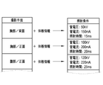
- the information on the imaging technique is used together with the physique information of the subject H for the technician RG to determine the irradiation conditions of the radiation source 11 .
- the technician RG considers the physique information (mainly body thickness) of the subject H, estimates the thickness of the chest, and determines the tube voltage, tube current, and determine the irradiation time.
- the irradiation dose is defined by the mAs value, which is the product of tube current and irradiation time.
- the PACS stores radiographic images XP captured by the radiographic imaging system 10.
- the console 14 transmits the radiation image XP received from the electronic cassette 13 to the PACS in a state of being associated with the imaging order 31 .
- the radiographic image XP is saved after being converted into an image file in a format conforming to the DICOM (Digital Imaging and Communication in Medicine) standard, for example.
- the radiographic image XP stored in the PACS is available for viewing by the doctor of the medical department that issued the radiographing order 31 .
- the console 14 is composed of a computer such as a personal computer or workstation.
- the console 14 has an order reception function for receiving the radiographing order 31, a setting function for various settings of the electronic cassette 13, and a function for displaying the radiation image XP received from the electronic cassette 13 on the display 14C.
- the console 14 has the above-described shooting support function.
- the console 14 includes an imaging order reception unit 14A and an imaging technique determination unit 14B as components related to the imaging support function.
- the radiographing order reception unit 14A displays the radiographing order 31 received from the RIS on the display 14C.
- the imaging maneuver determination unit 14B derives the imaging maneuver of the subject H who is positioned by performing image analysis on the camera image CP using the learned model LM.
- the imaging maneuver determination unit 14B outputs a determination result 32 including the imaging maneuver derived by the learned model LM.
- the console 14 displays, on the display 14C, a positioning confirmation screen 36 including the imaging order 31 received by the imaging order receiving unit 14A and the determination result 32 by the imaging maneuver determining unit 14B.
- the imaging order 31 and the determination result 32 are displayed side by side for easy comparison.
- a message 31A such as "The radiographing order is 'chest/back'" is displayed by extracting only the portion related to the radiographing procedure.
- the determination result 32 includes the imaging maneuver determined by the imaging maneuver determination unit 14B (in the example of FIG. 4, “chest/back” and the camera image CP.
- the imaging maneuver is an example is displayed in the form of a message such as "The imaging technique determined from the camera image is 'chest/back'.”
- the technician RG visually checks the radiographing order 31 and the radiographing technique included in the determination result 32, thereby confirming whether the positioning state of the subject H conforms to the radiographing order 31. can do.
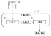
- a convolutional neural network (CNN) suitable for image analysis is used as the trained model LM.
- the trained model LM has, for example, an encoder 37 and a classifier 38 .
- the encoder 37 is composed of a CNN, and extracts multiple types of feature maps representing the features of the camera image CP by performing convolution processing and pooling processing on the camera image CP.
- convolution is spatial filtering processing using multiple types of filters having a size such as 3 ⁇ 3, for example.
- a filter coefficient is assigned to each of the 9 squares.
- the center square of such a filter is aligned with the pixel of interest of the camera image CP, and the product sum of the pixel values of a total of 9 pixels, ie, the pixel of interest and the 8 pixels surrounding it, is output.
- the output sum of products represents the feature amount of the region of interest to which the filter is applied.
- a feature map having a feature amount equivalent to the number of pixels of the camera image CP is output.
- multiple types of filters with different filter coefficients multiple types of feature maps are output.
- the number of feature maps corresponding to the number of filters is also called the number of channels.
- Such convolution is repeated while reducing the size of the camera image CP.
- Processing for reducing the camera image CP is called pooling processing.
- the pooling process is performed by thinning out and averaging adjacent pixels.
- the size of the camera image CP is reduced in steps of 1/2, 1/4, and 1/8.
- a multi-channel feature map is output for each size of the camera image CP.
- the feature map when the camera image CP is large represents the microscopic features of the subject depicted in the camera image CP
- the feature map when the size is small represents the macroscopic features of the subject depicted in the camera image CP. characterize.
- the encoder 37 extracts a multi-channel feature map representing macroscopic and microscopic features of the camera image CP by performing such convolution processing and pooling processing on the camera image CP.
- the learned model LM is, for example, a classification model that derives one imaging technique with the highest probability as the imaging technique indicated by the camera image CP from among a plurality of imaging techniques. Therefore, a classification unit 38 is provided as a configuration for deriving one imaging technique based on the feature amount of the camera image CP extracted by the encoder 37 .
- the classification unit 38 includes, for example, multiple perceptrons having one output node for multiple input nodes. Also, the perceptron is assigned weights that indicate the importance of multiple input nodes. In each perceptron, the sum of products, which is the sum of values obtained by multiplying the input values input to a plurality of input nodes by weights, is output from the output node as an output value.
- Such perceptrons are formulated by an activation function, such as a sigmoid function, for example.
- the outputs and inputs of multiple perceptrons are combined to form a multi-level neural network having multiple intermediate layers between the input layer and the output layer.
- a method of connecting a plurality of perceptrons between hierarchies for example, a full connection in which all output nodes of the previous hierarchy are connected to one input node of the next hierarchy is adopted.
- the input layer of the classification unit 38 all feature amounts included in the feature map of the camera image CP are input.
- the perceptrons forming each layer of the classification unit 38 feature values are input to input nodes as input values. Then, the sum of products, which is the sum of the values obtained by multiplying the feature amounts by the weights for each input node, is output from the output node as an output value, and the output value is handed over to the input node of the perceptron in the next layer.
- the output layer of the final hierarchy outputs the respective probabilities of a plurality of types of imaging techniques using a softmax function or the like based on the output values of the plurality of perceptrons. Based on this probability, one most likely imaging technique is derived.
- FIG. 5 shows an example in which an imaging technique of "chest/back" is derived based on the camera image CP.
- This example is just an example, and another mode may be used as the learned model LM as long as it is a classification model that can derive an imaging technique based on the camera image CP.
- FIG. 6 shows the hardware configuration of the learning device 40.
- the learning device 40 is configured by a computer such as a personal computer or workstation.
- the learning device 40 includes a display 41 , an input device 42 , a CPU 43 , a memory 44 , a storage device 46 and a communication section 47 . These are interconnected via a data bus 48 .
- the display 41 is a display unit that displays various operation screens provided with operation functions by GUI (Graphical User Interface).
- the input device 42 is an input operation unit including a touch panel, keyboard, or the like.
- the storage device 46 is composed of, for example, a HDD (Hard Disk Drive) and an SSD (Solid State Drive), and is built into the learning device 40 or externally connected to the learning device 40. External connections are made through cables or networks.
- the storage device 46 stores a control program such as an operating system, various application programs, various data associated with these programs, and the like.
- One of the various application programs includes an operating program AP that causes the computer to function as the learning device 40.
- the various data include a machine learning model LM0 to be subjected to learning processing, a trained model LM for which learning processing has been completed, teacher data TD used for learning, and three-dimensional computer graphics data (hereinafter referred to as 3DCG data) 56. , and parameter designation information 61 are included.
- the memory 44 is a work memory for the CPU 43 to execute processing.
- the CPU 43 loads a program stored in the storage device 46 into the memory 44 and executes processing according to the program, thereby comprehensively controlling each section of the learning device 40 .
- the communication unit 47 communicates with the console 14 via the network N.
- the communication unit 47 for example, transmits the learned model LM from the learning device 40 to the console 14, and transmits the learned model LM from the console 14 to the learning device 40 for additional learning of the learned model LM of the console 14. etc., is used to transfer the learned model LM.
- the hardware configuration of the computer for realizing the learning device 40 is shown in FIG. 6, the hardware configuration of the console 14 described above is the same. That is, the configuration of the imaging order reception unit 14A and the imaging technique determination unit 14B of the console 14 includes a processor such as the CPU 43, a memory such as the memory 44 built into or connected to the CPU 43, and a program executed by the CPU 43. realized by a processor such as the CPU 43, a memory such as the memory 44 built into or connected to the CPU 43, and a program executed by the CPU 43. realized by a processor such as the CPU 43, a memory such as the memory 44 built into or connected to the CPU 43, and a program executed by the CPU 43. realized by a processor such as the CPU 43, a memory such as the memory 44 built into or connected to the CPU 43, and a program executed by the CPU 43. realized by a processor such as the CPU 43, a memory such as the memory 44 built into or connected to the CPU 43, and a program executed by the CPU 43. realized by a processor such as the
- the learning device 40 has a teacher data generation unit 51 and a learning unit 52. Each of these processing units is implemented by the CPU 43 .
- the teacher data generation unit 51 generates a plurality of human body pseudo images SP generated based on the human body model 56A configured by the 3DCG data 56 for each imaging technique, which is a combination of imaging regions and imaging directions.
- the pseudo image SP is a two-dimensional image that simulates the subject H positioned with respect to the radiation imaging system 10, which is an example of a medical imaging apparatus.
- the teacher data generation unit 51 generates the pseudo image SP based on the three-dimensional computer graphics data (hereinafter referred to as 3DCG data) 56 and the parameter designation information 61.
- the parameter designation information 61 includes modeling parameter (hereinafter referred to as M-parameter) designation information 61M that is designated when modeling a three-dimensional human body model 56A imitating the human body, and rendering of the human body model 56A by setting a viewpoint.
- the training data generation unit 51 generates training data TD composed of the generated pseudo image SP and the correct data AD for the combination of the imaging region and imaging direction.
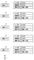
- the training data TD shown in FIG. 7 is an example when the imaging technique, which is a combination of the imaging region and the imaging direction, is "chest/back". That is, in the teacher data TD shown in FIG. 7, the pseudo image SP shows the back of the chest of the human body, and is an image showing the "chest/back" as the imaging technique. is also "chest/back".
- the learning unit 52 has a main processing unit 52A, an evaluation unit 52B, and an update unit 52C.
- the main processing unit 52A reads the machine learning model LM0 to be subjected to the learning process from the storage device 46, and inputs the pseudo image SP to the read machine learning model LM0. Then, the machine learning model LM0 is caused to execute a process of deriving an imaging technique indicated by the input pseudo image SP.
- the basic configuration of the machine learning model LM0 is the same as the trained model LM described in FIG. The value is different from the trained model LM.
- the main processing unit 52A outputs the imaging technique derived by the machine learning model LM0 as the output data OD to the evaluation unit 52B.
- the evaluation unit 52B compares the output data OD with the correct data AD included in the teacher data TD, and uses a loss function to evaluate the difference between the two as a loss.
- a loss function As with the learned model LM described above, in the machine learning model LM0 of this example, a plurality of imaging techniques indicated by the pseudo image SP are output as probabilities. Therefore, there is a loss when the imaging technique of the output data OD is incorrect. The difference is evaluated as a loss.
- the evaluating unit 52B outputs the evaluated loss to the updating unit 52C as an evaluation result.
- the updating unit 52C updates values such as the filter coefficients in the encoder 37 and the perceptron weights in the classifying unit 38 so that the loss included in the evaluation result is reduced.
- a series of processes from the input of the teacher data TD to the update are repeated until the end timing arrives.
- the end timing is, for example, when learning of all of the planned number of teacher data TD is completed, or when the loss falls below the target value.
- the method of generating the pseudo image SP executed by the teacher data generation unit 51 will be described in detail below with reference to FIGS. 8 to 15.
- FIG. First, the configuration of the 3DCG data 56 will be described with reference to FIG.
- the 3DCG data 56 of this example is data for constructing a human body model 56A.
- the 3DCG data 56 has modeling parameters (referred to as M-parameters) 56B in addition to configuration data of a human body model 56A.
- the human body model 56A is three-dimensional (X-, Y-, and Z-direction) data representing a human body.
- the M-parameters 56B are parameters that can be changed when modeling the human body model 56A, and are parameters for changing at least one of the posture and appearance of the human body model 56A.
- the M-parameter 56B is a parameter designated by the M-parameter designation information 61M.
- the M-parameters 56B include, for example, various items such as physique information, gender, posture information, skin color, hair color, hairstyle, and clothing.
- Physique information includes height, weight, sitting height, inseam length, head circumference, neck circumference, shoulder width, chest circumference, waist circumference, hand length, wrist circumference, hand width, leg length, foot width, thigh circumference, and calf. It has various items such as surroundings.
- the posture information includes items indicating the basic postures such as standing, lying, and sitting, as well as items such as whether or not limbs are bent.
- the M-parameter 56B may be designed so that internal rotation or external rotation of the knee joint can be specified. In this case, the inside or outside turning direction and the turning angle may be specified.
- bendable joints 57 are set in advance, and the places where the joints 57 are set can be bent.
- M-parameters 56B it is possible to change the pose and appearance of the human body when modeling the human body model 56A.
- the number and locations of the joints 57 may be changed arbitrarily. Accordingly, by setting a large number of joints 57 of the human body model 56A, it is possible to make the human body model 56A assume complicated postures.
- the number of joints 57 to be small, the number of M-parameters 56B can be reduced, and the processing speed of modeling can be increased.
- the teacher data generation unit 51 has a modeling unit 51A and a rendering unit 51B.
- the modeling section 51A models a human body model 56A having the posture and appearance of the human body designated by the M-parameter designation information 61M.
- the M-parameter designation information 61M includes a plurality of M-parameter sets MPS. A human body model 56A with a different pose and appearance is generated for each M-parameter set MPS.
- a height of 170 cm and a weight of 70 kg are specified as physique information, and male is specified as gender.
- the posture information it is specified that the user is in a standing position and that the arms and legs are not bent.
- the modeling unit 51A Based on this M-parameter set MPS1, the modeling unit 51A generates 3DCG data 56 having a human body model 56A_MPS1 having the posture and appearance specified by the M-parameter set MPS1.
- the M-parameter 56B shown in FIG. 8 by specifying the skin color, hairstyle, hair color, etc. in the M-parameter set MPS, the skin color, hairstyle, hair color, etc. of the human body model 56A It is also possible to change the color of It is also possible to change the clothes of the human body model 56A by specifying the clothes in the M-parameter set MPS.
- the M-parameters 56B include information related to appearance such as physique information and skin color, and posture information. Therefore, by changing physical information or information related to appearance such as skin color without changing posture information, a plurality of human models 56A having the same posture but different appearances can be generated or information related to appearance can be changed.
- the human body model 56A it is possible to generate the human body model 56A with different postures without using the Also, when the imaging region is the chest, the hairstyle and hair color are often not captured in the chest camera image CP, but when the imaging region is the head, they are captured in the head camera image CP. Therefore, when generating a pseudo image SP of the head, it is effective to be able to change the hairstyle and hair color.
- the rendering unit 51B uses the human body model 56A modeled by the modeling unit 51A (the human body model 56A_MPS1 in the examples of FIGS. 9 and 10) to render the human body model 56A from a set viewpoint, thereby creating a two-dimensional pseudo image SP. It is possible to generate In line with this example, rendering is a process of virtually performing a process of obtaining a camera image CP of the subject H using the optical camera 15 using the 3DCG data 56 . That is, a virtual camera 15V corresponding to the optical camera 15 is set in a three-dimensional space in which the human body model 56A is arranged, and the human body model 56A imitating the subject H is virtually photographed. Acquire a pseudo image SP.
- the R-parameter designation information 61R includes a plurality of R-parameter sets RPS.
- a pseudo image SP is generated for each R-parameter set RPS.
- the R-parameter set RPS is information specifying the viewpoint position and the like when the rendering unit 51B renders the human body model 56A.
- the R-parameter set RPS1 shown in FIGS. 9 and 10 includes, as an example, imaging technique information and virtual camera information.
- the imaging technique information includes an imaging region and an imaging direction.
- "chest/back" is specified as the imaging technique information
- the position of the virtual camera 15V is roughly set to a position where the chest of the human body model 56A can be imaged from the back.
- the virtual camera information is information that defines the position and the like of the virtual camera 15V in more detail, and the shooting distance, focal length, installation height, viewpoint direction, and the like are set.
- the shooting distance is the distance from the virtual camera 15V to the human body model 56A. Since the virtual camera 15V is a virtual image of the optical camera 15 attached to the radiation source 11, the imaging distance corresponds to SID (Source to image receptor distance), which is the distance between the radiation source 11 and the electronic cassette 13. is set as The SID is a value that is appropriately changed according to the imaging technique or the like, and the imaging distance in the example of FIG. 9 is set to 90 cm.
- the focal length is information for defining the angle of view of the virtual camera 15V.
- the photographing range SR (see FIGS. 11 and 12, etc.) of the virtual camera 15V is defined.
- the imaging range SR is set to a size that includes the irradiation field of the radiation source 11 .
- the focal length is set to 40 mm as an example.
- the installation height is the position in the Z direction where the virtual camera 15V is installed, and is set according to the body part to be imaged. In this example, since the imaging part is the chest, the height is set to the chest of the standing human body model 56A.
- the viewpoint direction is set according to the posture of the human body model 56A and the imaging direction of the imaging technique. In the example shown in FIG. 10, since the human body model 56A is in a standing position and the shooting direction is the back, the -Y direction is set.
- the rendering unit 51B can change the viewpoint for generating the pseudo image SP according to the R-parameter set RPS.
- the rendering unit 51B renders the human body model 56A based on the R-parameter set RPS.
- a pseudo image SP is thus generated.
- a human body model 56A_MPS1 modeled by the modeling unit 51A based on the specification of the M-parameter set MPS1 is rendered by the rendering unit 51B based on the specification of the R-parameter set RPS1 to create a pseudo image SP1-1. is generated.
- a virtual cassette 13V which is a virtual electronic cassette 13 is arranged in the three-dimensional space in which the human body model 56A is arranged. This is shown for convenience in order to clarify the position of the imaging part.
- the virtual cassette 13V may also be modeled in addition to the human body model 56A during modeling, and rendering may be performed including the modeled virtual cassette 13V.
- FIG. 11 shows an example in which the imaging technique generates a pseudo image SP of "chest/front".
- the M-parameter set MPS1 in FIG. 11 is similar to the example in FIG. 10, and the human body model 56A_MPS1 is similar to the example in FIG.
- the R-parameter set RPS2 in FIG. 11 differs from the R-parameter set RPS1 in FIG. 10 in that the imaging direction is changed from "rear” to "front".
- the viewpoint direction of the virtual camera information is changed to the "Y direction” along with the change of the photographing direction.
- the R-parameter set RPS2 of FIG. 11 is otherwise the same as the R-parameter set RPS1 of FIG.
- the position of the virtual camera 15V, etc. are set and rendering is performed.
- the “chest” of the human body model 56A_MPS1 is photographed from the “front” to generate a pseudo image SP1-2 corresponding to the “chest/front” photographing technique.
- FIG. 12 shows an example of generating a pseudo image SP of the "abdomen/front” imaging technique.
- the M-parameter set MPS1 in FIG. 12 is similar to the examples in FIGS. 10 and 11, and the human body model 56A_MPS1 is similar to the examples in FIGS.
- the R-parameter set RPS3 in FIG. 12 differs from the R-parameter set RPS1 in FIG. 10 in that the imaging region is changed from "chest" to "abdomen".
- the shooting direction is "front", which is different from “back” in FIG. 10, but is the same as the example in FIG.
- the R-parameter set RPS3 of FIG. 12 is otherwise the same as the R-parameter set RPS2 of FIG.
- FIG. 13 shows an example of generating a pseudo image SP with an imaging technique of "both knees/front".
- the M-parameter set MPS2 in FIG. 13 specifies “sitting position” and “both legs bent” as posture information.
- the human body model 56A_MPS2 is modeled in a sitting position with both legs bent.
- the imaging technique information designates “both knees” as the imaging region and “front” as the imaging direction.
- an installation height of 150 cm is specified as the height at which both knees of the human body model 56A_MPS2 in a sitting posture can be photographed from the front, and the photographing direction is downward in the Z direction, that is, the “ ⁇ Z direction”. specified.
- the example of FIG. 14 has the same R-parameter set RPS2 as the example of FIG.
- the difference is the physique information of the M-parameter set MPS4 of FIG. 14, which has larger values of body weight, chest circumference, waist circumference and the like (not shown) than the M-parameter set MPS1 of FIG.
- the human body model 56A_MPS4 modeled based on the M-parameter set MPS4 of FIG. 14 is fatter than the human body model 56A_MPS1 of FIG.
- Other points are the same as the example of FIG.
- a pseudo image SP4-2 corresponding to the “chest/front” imaging technique is generated for the fat physique human body model 56A_MPS4.
- FIG. 15 like FIG. 13, shows an example of generating a pseudo image SP with an imaging technique of "both knees/front".
- the difference from the example in FIG. 13 is that the skin color is designated as brown in the M-parameter set MPS5.
- Other points are the same as the example of FIG.
- a pseudo image SP5-4 of "both knees/front” is generated for the human body model 56A_MPS5 whose skin color is brown.
- the teacher data generation unit 51 Based on the parameter designation information 61, the teacher data generation unit 51 generates a plurality of pseudo images SP for each combination of imaging parts and imaging directions. For example, the training data generation unit 51 uses different parameter sets (M-parameter set MPS and R-parameter set RPS) for each imaging procedure such as “chest/front” and “chest/back” to simulate the pseudo image SP.
- M-parameter set MPS and R-parameter set RPS for each imaging procedure such as “chest/front” and “chest/back” to simulate the pseudo image SP.
- FIG. 16 As shown in the main flowchart of FIG. 16, the learning device 40 generates teacher data TD based on 3DCG data (step S100), and makes the machine learning model LM0 learn using the generated teacher data TD (step S200). .
- FIG. 17 shows details of step S100 for generating teacher data TD.
- the teacher data generator 51 of the learning device 40 acquires the 3DCG data 56 (step S101).
- the teacher data generator 51 acquires parameter designation information 61 .
- the teacher data generator 51 reads the 3DCG data 56 and parameter designation information 61 stored in the storage device 46 from the storage device 46.
- a plurality of M-parameter sets MPS and a plurality of R-parameter sets RPS are recorded in the parameter designation information 61.
- the teacher data generation unit 51 performs modeling and rendering for each combination of one M-parameter set MPS and one R-parameter set RPS, as illustrated in FIGS.
- a pseudo image SP is generated (step S103).
- the teacher data generating unit 51 generates teacher data TD by combining the generated pseudo image SP and correct data AD (step S104).
- the generated teacher data TD are stored in the storage device 46 .
- step S105 if there is a parameter set that has not been input among the parameter sets (a combination of the M-parameter set MPS and the R-parameter set RPS) included in the acquired parameter designation information 61, the teacher data generation unit 51 ( YES at step S105), the processes of steps S103 and S104 are executed.
- the teacher data generation unit 51 generates a plurality of pseudo images SP using different parameter sets (M-parameter set MPS and R-parameter set RPS) for each imaging technique such as “chest/front” and “chest/back”. Generate. If there is no parameter set that has not been input (NO in step S105), the teacher data generation process is terminated.
- FIG. 18 shows the details of step S200 for learning the machine learning model LM0 using the generated teacher data TD.
- step S200 first, in the learning unit 52 of the learning device 40, the main processing unit 52A acquires the machine learning model LM0 from the storage device 46 (step S201). Then, the main processing unit 52A acquires the teacher data TD generated by the teacher data generation unit 51 from the storage device 46, and inputs the pseudo images SP included in the teacher data TD to the machine learning model LM0 one by one (step S202). Then, the main processing unit 52A causes the machine learning model LM0 to derive the output data OD including the imaging technique (step S203).
- the evaluation unit 52B compares the correct data AD and the output data OD to evaluate the output data OD (step S204).
- the updating unit 52C updates values such as the filter coefficients and perceptron weights of the machine learning model LM0 based on the evaluation result of the output data OD (step S205).
- the learning unit 52 repeats a series of processes from step S202 to step S205.
- the learning unit 52 ends learning.
- the learning device 40 is a pseudo image SP of a human body generated based on the human body model 56A configured by 3DCG data, and is a radiation imaging system as an example of a medical imaging device.
- a plurality of pseudo images SP simulating the subject H positioned with respect to 10 are generated for each combination of imaging region and imaging direction.
- the machine learning model LM0 is learned using a plurality of teacher data TD composed of the generated pseudo image SP and the combined correct data AD.
- a pseudo image SP forming the teacher data TD is generated based on a human body model 56A formed of 3DCG data.
- the trained model LM for deriving the photographed part and photographing direction of the subject H captured in the camera image CP can be efficiently learned as compared with the case where only the camera image CP is used as the teacher data TD. .
- the 3DCG data of the above example is accompanied by M-parameters 56B for changing at least one of the posture and appearance of the human body model 56A. Therefore, for example, by simply changing the M-parameter 56B using the parameter designation information 61, it is possible to generate a plurality of pseudo images SP in which at least one of the posture and appearance of the human body model 56A is different. Therefore, it is easy to generate various pseudo images SP in which at least one of the posture and appearance of the human body model 56A is different.
- the actual posture or appearance of the subject H also varies from person to person. It takes a lot of time and effort to collect camera images CP of various subjects H or camera images CP of subjects H in various postures. In view of these circumstances, a method of simply changing the posture or appearance of the human body model 56A by changing the M-parameters 56B is very effective.
- the M-parameters 56B include at least one of physique information, gender, posture information, skin color, hair color, hairstyle, and clothes of the human body model 56A.
- the machine learning model LM0 can be learned using the pseudo images SP of the human body models 56A imitating the subjects H with various appearances as the teacher data TD. This makes it possible to improve the accuracy of deriving the imaging part and imaging direction from the camera image CP in the learned model LM, compared to the case where the physique information and the like cannot be designated.
- the physique information includes height, weight, sitting height, crotch length, head circumference, head width, neck circumference, shoulder width, chest circumference (bust), waist circumference (waist), hand length, wrist circumference,
- hand width, foot length, foot width, thigh circumference, calf circumference, and the like may be included.
- the more items of physique information the more diversity of the human body model 56A can be ensured, which is preferable.
- the example in which the height and weight are defined by numerical values has been described, but evaluation information such as detailed, standard, and thick items may be used instead of the numerical values.
- the rendering unit 51B can generate a pseudo image SP by rendering the human body model 56A from a set viewpoint, and the viewpoint is defined by the R-parameter set RPS that defines the rendering parameters. Can be changed. Therefore, compared to the case without such rendering parameters, it becomes easier to change the viewpoint, and it is easier to generate various pseudo images SP.
- the viewpoint information for setting the viewpoint includes the focal length of the virtual camera 15V that is virtually installed at the viewpoint and the shooting distance that is the distance from the virtual camera 15V to the human body model 56A. Since the photographing distance and the focal length can be changed, it is easy to change the photographing range SR of the virtual camera 15V.
- the technique of the present disclosure is applied to the radiation imaging system 10, which is an example of a medical imaging apparatus and a radiation imaging apparatus, has been described.
- radiography there are many types of radiographing orders, such as "chest/front”, “abdomen/front”, and “both legs/front”, that specify combinations of radiographic regions and radiographic directions. This case is particularly effective when used in a medical imaging apparatus with many types of imaging orders.
- batch processing may be executed to continuously generate a plurality of pseudo images SP.
- the parameter designation information 91 has M-parameter designation information 61M and R-parameter designation information 61R. Then, as shown in FIG. 9, it is possible to designate a plurality of M-parameter sets MPS in the M-parameter designation information 61M, and a plurality of R-parameter sets RPS in the R-parameter designation information 61R. can be specified.
- One pseudo image SP is generated by specifying a set of the M-parameter set MPS and the R-parameter set RPS. Therefore, by using the parameter designation information 91, it is possible to execute batch processing for continuously generating a plurality of pseudo images SP. Such batch processing is possible when the pseudo image SP is generated using the 3DCG data 56 . By performing batch processing, it is possible to efficiently generate a plurality of pseudo images SP.
- the optical camera 15 takes still images, but moving images may be taken.
- the radiographer RG inputs a shooting instruction before starting the positioning of the subject H, causing the optical camera 15 to start shooting a moving image, and the moving image shot by the optical camera 15 is displayed. may be sent to the console 14 in real time.
- frame images forming a moving image are used as input data for the trained model LM.
- Modification 1 In the above example, only the pseudo image SP is used as the training data TD. However, as shown in FIG. good.
- the teacher data TD composed of the pseudo image SP and the correct data AD is set as the first teacher data
- the teacher data composed of the camera image CP and the correct data AD is set as the second teacher data TD2.
- the learning unit 52 uses both the first teacher data TD and the second teacher data TD2 to learn the machine learning model LM0. By learning using the camera images CP used when the trained model LM is operated, the accuracy of deriving the imaging region and imaging direction is improved compared to the case of using only the pseudo images SP.
- the imaging maneuver determination unit 14B determines the imaging maneuver (such as "chest/back") included in the imaging order 31 and the learned model LM
- the derived imaging technique (such as “chest/back”) is directly output to the display 14C.
- a matching unit 14D is provided in the imaging maneuver determination unit 14B, and the matching unit 14D collates the imaging maneuver included in the imaging order 31 with the imaging maneuver derived by the learned model LM. good too.
- the collation unit 14D may output a collation result indicating whether or not the imaging techniques of the two match, and display the collation result on the positioning confirmation screen 36 .
- FIG. 20 In the example of FIG.
- the matching result is displayed in the form of a message such as "The determined imaging technique matches the imaging order." Further, if the collation result indicates that the imaging techniques of the two do not match, a message (not shown) such as "the determined imaging technique does not match the imaging order" is displayed on the positioning confirmation screen 36. Displayed as matching results. Such a message functions as an alert to make the engineer RG aware of the positioning error. Furthermore, a voice, warning sound, warning lamp, etc. may be used as an alert.
- the learning device 40 has the teacher data generation unit 51, and the learning device 40 also functions as a teacher data generation device. It is good also as the apparatus which carried out.
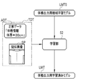
- a trained model LMT for physique output is considered, which uses a camera image CP as an input and derives physique information representing the physique of the subject H captured in the camera image CP.
- the second embodiment is an example of using a pseudo image SP for learning a physique output machine learning model LMT0, which is the base of the physique output trained model LMT, in order to generate such a physique output trained model LMT.
- the physique output trained model LMT includes an encoder 37 and a regression unit 68, for example.
- the encoder 37 is the same as the learned model LM for deriving the imaging technique shown in FIG.
- the physique output trained model LMT is a regression model for estimating, for example, a numerical value of body thickness as physique information of the subject H captured in the camera image CP from the feature map of the camera image CP.
- the regression unit 68 for example, a linear regression model, a support vector machine, or the like is used.
- the learning unit 52 learns the physique output machine learning model LMT0 using a plurality of physique output teacher data TDT using the pseudo image SP.
- the physique output training data TDT is composed of a pseudo image SP and correct data ADT of physique information representing the physique of the human body model 56A.
- the body thickness of the subject H is used as basic information when determining irradiation conditions. Therefore, if the body thickness can be derived from the camera image CP, the convenience in radiography will be improved.
- a third embodiment shown in FIG. 23 is an example in which the technology of the present disclosure is applied to an ultrasonic imaging apparatus as a medical imaging apparatus.
- the ultrasonic imaging apparatus has a probe 71 having an ultrasonic transmitter and a receiver. Ultrasonic imaging is performed by bringing the probe 71 into contact with the body part of the subject H to be imaged. Also in ultrasonic imaging, an imaging region is designated by an imaging order, and an imaging direction (orientation of the probe 71) may also be determined according to the imaging purpose. If the imaging region and imaging direction are inappropriate, an appropriate ultrasound image may not be obtained.
- ultrasound imaging unlike radiography, can be performed not only by doctors but also by nurses and caregivers.
- a case of shooting is also being assumed.
- use of the camera image CP for shooting guidance is also under consideration.
- the learned model LM which derives the imaged part and the imaged direction from the camera image CP as an input, will be used more often. That is, in ultrasonic imaging, the camera image CP shows the state in which the probe 71 is applied to the imaging site of the subject H, that is, the state of the subject H positioned with respect to the probe 71.
- the teacher data generation unit 51 sets the state in which the human body model 56A and the virtual probe 71 are positioned by the virtual camera 15V.
- a pseudo image SP is generated by rendering from a different viewpoint.
- a machine learning model LM is learned using the teacher data TD of the generated pseudo image SP.
- the hardware structure of a processing unit that executes various processes is the following various processors: be.
- processors include CPUs, Programmable Logic Devices (PLDs), dedicated electric circuits, etc.
- the CPU is a general-purpose processor that executes software (programs) and functions as various processing units.
- a PLD is a processor such as an FPGA (Field Programmable Gate Array) whose circuit configuration can be changed after manufacturing.
- a dedicated electric circuit is a processor, such as an ASIC (Application Specific Integrated Circuit), having a circuit configuration specially designed to execute specific processing.
- One processing unit may be composed of one of these various processors, or composed of a combination of two or more processors of the same type or different types (for example, a plurality of FPGAs or a combination of a CPU and an FPGA).
- a plurality of processing units may be configured by one processor.
- As an example of configuring a plurality of processing units in one processor first, there is a mode in which one processor is configured by combining one or more CPUs and software, and this processor functions as a plurality of processing units. .
- SoC System On Chip
- the various processing units are configured using one or more of the above various processors as a hardware structure.
- the hardware structure of these various processors is, more specifically, an electrical circuit that combines circuit elements such as semiconductor elements.
- the technology of the present disclosure is not limited to the above-described embodiments, and can of course adopt various configurations without departing from the gist of the technology of the present disclosure. Furthermore, the technology of the present disclosure extends to a computer-readable storage medium that non-temporarily stores the program in addition to the program.
Landscapes
- Engineering & Computer Science (AREA)
- Health & Medical Sciences (AREA)
- Life Sciences & Earth Sciences (AREA)
- Physics & Mathematics (AREA)
- Theoretical Computer Science (AREA)
- Medical Informatics (AREA)
- General Health & Medical Sciences (AREA)
- General Physics & Mathematics (AREA)
- Biomedical Technology (AREA)
- Biophysics (AREA)
- Molecular Biology (AREA)
- Software Systems (AREA)
- General Engineering & Computer Science (AREA)
- Radiology & Medical Imaging (AREA)
- Nuclear Medicine, Radiotherapy & Molecular Imaging (AREA)
- Evolutionary Computation (AREA)
- Animal Behavior & Ethology (AREA)
- Computing Systems (AREA)
- Data Mining & Analysis (AREA)
- Artificial Intelligence (AREA)
- Mathematical Physics (AREA)
- Veterinary Medicine (AREA)
- Public Health (AREA)
- Pathology (AREA)
- Heart & Thoracic Surgery (AREA)
- Surgery (AREA)
- Computer Vision & Pattern Recognition (AREA)
- Computational Linguistics (AREA)
- Quality & Reliability (AREA)
- High Energy & Nuclear Physics (AREA)
- Optics & Photonics (AREA)
- Oral & Maxillofacial Surgery (AREA)
- Dentistry (AREA)
- Computer Graphics (AREA)
- Computer Hardware Design (AREA)
- Image Analysis (AREA)
Priority Applications (4)
| Application Number | Priority Date | Filing Date | Title |
|---|---|---|---|
| CN202280013806.7A CN116829074B (zh) | 2021-02-17 | 2022-02-14 | 学习装置、学习方法、记录介质、教师数据生成装置、机器学习模型及医疗用摄影装置 |
| JP2023500828A JPWO2022176813A1 (https=) | 2021-02-17 | 2022-02-14 | |
| EP22756131.3A EP4295771A4 (en) | 2021-02-17 | 2022-02-14 | Learning device, learning method, learning device operation program, training data generation device, machine learning model and medical imaging device |
| US18/360,817 US12608800B2 (en) | 2021-02-17 | 2023-07-28 | Learning device, learning method, operation program of learning device, teacher data generation device, machine learning model, and medical imaging apparatus |
Applications Claiming Priority (2)
| Application Number | Priority Date | Filing Date | Title |
|---|---|---|---|
| JP2021-023759 | 2021-02-17 | ||
| JP2021023759 | 2021-02-17 |
Related Child Applications (1)
| Application Number | Title | Priority Date | Filing Date |
|---|---|---|---|
| US18/360,817 Continuation US12608800B2 (en) | 2021-02-17 | 2023-07-28 | Learning device, learning method, operation program of learning device, teacher data generation device, machine learning model, and medical imaging apparatus |
Publications (1)
| Publication Number | Publication Date |
|---|---|
| WO2022176813A1 true WO2022176813A1 (ja) | 2022-08-25 |
Family
ID=82930555
Family Applications (1)
| Application Number | Title | Priority Date | Filing Date |
|---|---|---|---|
| PCT/JP2022/005744 Ceased WO2022176813A1 (ja) | 2021-02-17 | 2022-02-14 | 学習装置、学習方法、学習装置の作動プログラム、教師データ生成装置、機械学習モデル及び医療用撮影装置 |
Country Status (5)
| Country | Link |
|---|---|
| US (1) | US12608800B2 (https=) |
| EP (1) | EP4295771A4 (https=) |
| JP (1) | JPWO2022176813A1 (https=) |
| CN (1) | CN116829074B (https=) |
| WO (1) | WO2022176813A1 (https=) |
Cited By (2)
| Publication number | Priority date | Publication date | Assignee | Title |
|---|---|---|---|---|
| CN116563246A (zh) * | 2023-05-10 | 2023-08-08 | 之江实验室 | 一种用于医学影像辅助诊断的训练样本生成方法及装置 |
| JP2025072132A (ja) * | 2023-10-24 | 2025-05-09 | キヤノン株式会社 | 情報処理装置、放射線撮影システム、情報処理方法、及びプログラム |
Citations (6)
| Publication number | Priority date | Publication date | Assignee | Title |
|---|---|---|---|---|
| JP2013102851A (ja) * | 2011-11-11 | 2013-05-30 | Konica Minolta Medical & Graphic Inc | 医用画像撮影システム、医用画像処理装置及びプログラム |
| US20200226752A1 (en) * | 2019-01-16 | 2020-07-16 | Samsung Electronics Co., Ltd. | Apparatus and method for processing medical image |
| WO2020209256A1 (ja) * | 2019-04-11 | 2020-10-15 | 富士フイルム株式会社 | 放射線撮影システム及びその作動方法並びに放射線撮影システム用コンソール |
| JP2020192440A (ja) | 2020-09-03 | 2020-12-03 | 富士フイルム株式会社 | 放射線撮影システムとその作動方法 |
| JP2020199163A (ja) * | 2019-06-12 | 2020-12-17 | キヤノン株式会社 | 放射線撮影支援システム、放射線撮影支援方法及びプログラム |
| WO2021020112A1 (ja) * | 2019-07-29 | 2021-02-04 | 富士フイルム株式会社 | 医用撮影システム及び医用撮影処理装置 |
Family Cites Families (17)
| Publication number | Priority date | Publication date | Assignee | Title |
|---|---|---|---|---|
| US9117289B2 (en) * | 2011-11-11 | 2015-08-25 | Konica Minolta, Inc. | Medical imaging system, medical image processing apparatus, and computer-readable medium |
| JP6265588B2 (ja) * | 2012-06-12 | 2018-01-24 | オリンパス株式会社 | 画像処理装置、画像処理装置の作動方法、及び画像処理プログラム |
| US9355123B2 (en) * | 2013-07-19 | 2016-05-31 | Nant Holdings Ip, Llc | Fast recognition algorithm processing, systems and methods |
| US9524582B2 (en) * | 2014-01-28 | 2016-12-20 | Siemens Healthcare Gmbh | Method and system for constructing personalized avatars using a parameterized deformable mesh |
| CN107194987B (zh) * | 2017-05-12 | 2021-12-10 | 西安蒜泥电子科技有限责任公司 | 对人体测量数据进行预测的方法 |
| JP6760901B2 (ja) * | 2017-08-10 | 2020-09-23 | 富士フイルム株式会社 | 放射線撮影システムとその作動方法 |
| CN109978640A (zh) * | 2017-12-27 | 2019-07-05 | 广东欧珀移动通信有限公司 | 服饰试穿方法、装置、存储介质及移动终端 |
| KR101862359B1 (ko) * | 2017-12-28 | 2018-06-29 | (주)휴톰 | 수술 시뮬레이션 정보 생성방법 및 프로그램 |
| CN108876814B (zh) * | 2018-01-11 | 2021-05-28 | 南京大学 | 一种生成姿态流图像的方法 |
| US11475630B2 (en) * | 2018-10-17 | 2022-10-18 | Midea Group Co., Ltd. | System and method for generating acupuncture points on reconstructed 3D human body model for physical therapy |
| JP7488037B2 (ja) * | 2018-10-24 | 2024-05-21 | キヤノンメディカルシステムズ株式会社 | 医用画像診断装置、医用画像診断方法、およびプログラム |
| US10881353B2 (en) * | 2019-06-03 | 2021-01-05 | General Electric Company | Machine-guided imaging techniques |
| EP3760125A1 (en) * | 2019-07-05 | 2021-01-06 | Koninklijke Philips N.V. | Self-learning distributed system with automated ground-truth generation |
| JP7328861B2 (ja) * | 2019-10-09 | 2023-08-17 | キヤノンメディカルシステムズ株式会社 | 医用情報処理装置、医用情報処理システム、医用情報処理プログラム、および医用画像撮像装置 |
| US11526697B1 (en) * | 2020-03-10 | 2022-12-13 | Amazon Technologies, Inc. | Three-dimensional pose estimation |
| US11562482B2 (en) * | 2020-03-30 | 2023-01-24 | Varian Medical Systems International Ag | Systems and methods for pseudo image data augmentation for training machine learning models |
| CN112287857A (zh) * | 2020-11-03 | 2021-01-29 | 北京享云智汇科技有限公司 | 一种多视角异常步态识别方法 |
-
2022
- 2022-02-14 EP EP22756131.3A patent/EP4295771A4/en active Pending
- 2022-02-14 CN CN202280013806.7A patent/CN116829074B/zh active Active
- 2022-02-14 JP JP2023500828A patent/JPWO2022176813A1/ja active Pending
- 2022-02-14 WO PCT/JP2022/005744 patent/WO2022176813A1/ja not_active Ceased
-
2023
- 2023-07-28 US US18/360,817 patent/US12608800B2/en active Active
Patent Citations (6)
| Publication number | Priority date | Publication date | Assignee | Title |
|---|---|---|---|---|
| JP2013102851A (ja) * | 2011-11-11 | 2013-05-30 | Konica Minolta Medical & Graphic Inc | 医用画像撮影システム、医用画像処理装置及びプログラム |
| US20200226752A1 (en) * | 2019-01-16 | 2020-07-16 | Samsung Electronics Co., Ltd. | Apparatus and method for processing medical image |
| WO2020209256A1 (ja) * | 2019-04-11 | 2020-10-15 | 富士フイルム株式会社 | 放射線撮影システム及びその作動方法並びに放射線撮影システム用コンソール |
| JP2020199163A (ja) * | 2019-06-12 | 2020-12-17 | キヤノン株式会社 | 放射線撮影支援システム、放射線撮影支援方法及びプログラム |
| WO2021020112A1 (ja) * | 2019-07-29 | 2021-02-04 | 富士フイルム株式会社 | 医用撮影システム及び医用撮影処理装置 |
| JP2020192440A (ja) | 2020-09-03 | 2020-12-03 | 富士フイルム株式会社 | 放射線撮影システムとその作動方法 |
Non-Patent Citations (1)
| Title |
|---|
| See also references of EP4295771A4 |
Cited By (4)
| Publication number | Priority date | Publication date | Assignee | Title |
|---|---|---|---|---|
| CN116563246A (zh) * | 2023-05-10 | 2023-08-08 | 之江实验室 | 一种用于医学影像辅助诊断的训练样本生成方法及装置 |
| CN116563246B (zh) * | 2023-05-10 | 2024-01-30 | 之江实验室 | 一种用于医学影像辅助诊断的训练样本生成方法及装置 |
| JP2025072132A (ja) * | 2023-10-24 | 2025-05-09 | キヤノン株式会社 | 情報処理装置、放射線撮影システム、情報処理方法、及びプログラム |
| JP7767373B2 (ja) | 2023-10-24 | 2025-11-11 | キヤノン株式会社 | 情報処理装置、放射線撮影システム、情報処理方法、及びプログラム |
Also Published As
| Publication number | Publication date |
|---|---|
| US20230368384A1 (en) | 2023-11-16 |
| EP4295771A1 (en) | 2023-12-27 |
| JPWO2022176813A1 (https=) | 2022-08-25 |
| CN116829074A (zh) | 2023-09-29 |
| EP4295771A4 (en) | 2024-08-14 |
| US12608800B2 (en) | 2026-04-21 |
| CN116829074B (zh) | 2026-03-24 |
Similar Documents
| Publication | Publication Date | Title |
|---|---|---|
| CN112022201B (zh) | 机器引导的成像技术 | |
| US10507002B2 (en) | X-ray system and method for standing subject | |
| US10170155B2 (en) | Motion information display apparatus and method | |
| CN105816190B (zh) | X射线记录系统 | |
| JP6181373B2 (ja) | 医用情報処理装置及びプログラム | |
| CN109381208A (zh) | 放射线摄影系统及其工作方法 | |
| JP2017202321A (ja) | 医用画像診断装置 | |
| US12608800B2 (en) | Learning device, learning method, operation program of learning device, teacher data generation device, machine learning model, and medical imaging apparatus | |
| JP6967983B2 (ja) | 画像処理装置、画像処理方法、及びプログラム | |
| JP7466541B2 (ja) | 医療用x線撮像機器の位置決め | |
| JP6598422B2 (ja) | 医用情報処理装置、システム及びプログラム | |
| JP2009028362A (ja) | 医用画像処理装置及び医用画像診断装置 | |
| CN113662573A (zh) | 乳腺病灶定位方法、装置、计算机设备和存储介质 | |
| CN111609908A (zh) | 根据表面数据、使用患者模型的患者体重估计 | |
| CN110267597B (zh) | 期望成像的解剖结构的定位和计算机断层摄影 | |
| JP6918443B2 (ja) | 医用情報処理装置 | |
| JP6956514B2 (ja) | X線ct装置及び医用情報管理装置 | |
| JP2014130519A (ja) | 医用情報処理システム、医用情報処理装置及び医用画像診断装置 | |
| JP7427136B2 (ja) | 一次元位置インジケータ | |
| CN117323581A (zh) | 表面引导的监测中确定感兴趣区的方法、系统和可读介质 | |
| JP7387409B2 (ja) | 医用画像処理装置、医用画像処理方法、医用画像処理プログラム | |
| JP7767373B2 (ja) | 情報処理装置、放射線撮影システム、情報処理方法、及びプログラム | |
| CN119970067B (zh) | 一种面向平片过程的摆位引导方法和系统、相关设备 | |
| EP4452078B1 (en) | Fluoroscopic positioning guidance | |
| EP4494564A1 (en) | Method for a positioning control of an object under investigation before acquiring a projective x-ray image |
Legal Events
| Date | Code | Title | Description |
|---|---|---|---|
| 121 | Ep: the epo has been informed by wipo that ep was designated in this application |
Ref document number: 22756131 Country of ref document: EP Kind code of ref document: A1 |
|
| WWE | Wipo information: entry into national phase |
Ref document number: 2023500828 Country of ref document: JP |
|
| WWE | Wipo information: entry into national phase |
Ref document number: 202280013806.7 Country of ref document: CN |
|
| WWE | Wipo information: entry into national phase |
Ref document number: 2022756131 Country of ref document: EP |
|
| NENP | Non-entry into the national phase |
Ref country code: DE |
|
| ENP | Entry into the national phase |
Ref document number: 2022756131 Country of ref document: EP Effective date: 20230918 |