WO2021020112A1 - 医用撮影システム及び医用撮影処理装置 - Google Patents
医用撮影システム及び医用撮影処理装置 Download PDFInfo
- Publication number
- WO2021020112A1 WO2021020112A1 PCT/JP2020/027395 JP2020027395W WO2021020112A1 WO 2021020112 A1 WO2021020112 A1 WO 2021020112A1 JP 2020027395 W JP2020027395 W JP 2020027395W WO 2021020112 A1 WO2021020112 A1 WO 2021020112A1
- Authority
- WO
- WIPO (PCT)
- Prior art keywords
- subject
- unit
- positioning data
- medical imaging
- subject obj
- Prior art date
Links
- 238000002059 diagnostic imaging Methods 0.000 claims description 65
- 238000003384 imaging method Methods 0.000 claims description 54
- 238000001514 detection method Methods 0.000 claims description 15
- 230000005855 radiation Effects 0.000 description 60
- 210000000629 knee joint Anatomy 0.000 description 22
- 238000002601 radiography Methods 0.000 description 13
- 238000003860 storage Methods 0.000 description 13
- 210000003857 wrist joint Anatomy 0.000 description 10
- 238000003745 diagnosis Methods 0.000 description 7
- 210000001699 lower leg Anatomy 0.000 description 7
- 210000000689 upper leg Anatomy 0.000 description 6
- 230000006870 function Effects 0.000 description 5
- 238000000034 method Methods 0.000 description 5
- 238000010586 diagram Methods 0.000 description 4
- 210000004513 dentition Anatomy 0.000 description 3
- 239000004973 liquid crystal related substance Substances 0.000 description 3
- 238000012986 modification Methods 0.000 description 3
- 230000004048 modification Effects 0.000 description 3
- 230000036346 tooth eruption Effects 0.000 description 3
- 230000003190 augmentative effect Effects 0.000 description 2
- 239000007787 solid Substances 0.000 description 2
- OWNRRUFOJXFKCU-UHFFFAOYSA-N Bromadiolone Chemical compound C=1C=C(C=2C=CC(Br)=CC=2)C=CC=1C(O)CC(C=1C(OC2=CC=CC=C2C=1O)=O)C1=CC=CC=C1 OWNRRUFOJXFKCU-UHFFFAOYSA-N 0.000 description 1
- 210000001015 abdomen Anatomy 0.000 description 1
- 238000005452 bending Methods 0.000 description 1
- 210000000988 bone and bone Anatomy 0.000 description 1
- 210000000845 cartilage Anatomy 0.000 description 1
- 210000000038 chest Anatomy 0.000 description 1
- 238000009826 distribution Methods 0.000 description 1
- 210000003128 head Anatomy 0.000 description 1
- 210000004394 hip joint Anatomy 0.000 description 1
- 210000001503 joint Anatomy 0.000 description 1
- 238000004519 manufacturing process Methods 0.000 description 1
- 210000003205 muscle Anatomy 0.000 description 1
- 239000002243 precursor Substances 0.000 description 1
- 238000003825 pressing Methods 0.000 description 1
- 239000004065 semiconductor Substances 0.000 description 1
Images


Classifications
-
- A—HUMAN NECESSITIES
- A61—MEDICAL OR VETERINARY SCIENCE; HYGIENE
- A61B—DIAGNOSIS; SURGERY; IDENTIFICATION
- A61B6/00—Apparatus for radiation diagnosis, e.g. combined with radiation therapy equipment
- A61B6/08—Auxiliary means for directing the radiation beam to a particular spot, e.g. using light beams
-
- A—HUMAN NECESSITIES
- A61—MEDICAL OR VETERINARY SCIENCE; HYGIENE
- A61B—DIAGNOSIS; SURGERY; IDENTIFICATION
- A61B6/00—Apparatus for radiation diagnosis, e.g. combined with radiation therapy equipment
- A61B6/40—Apparatus for radiation diagnosis, e.g. combined with radiation therapy equipment with arrangements for generating radiation specially adapted for radiation diagnosis
-
- A—HUMAN NECESSITIES
- A61—MEDICAL OR VETERINARY SCIENCE; HYGIENE
- A61B—DIAGNOSIS; SURGERY; IDENTIFICATION
- A61B6/00—Apparatus for radiation diagnosis, e.g. combined with radiation therapy equipment
- A61B6/04—Positioning of patients; Tiltable beds or the like
-
- A—HUMAN NECESSITIES
- A61—MEDICAL OR VETERINARY SCIENCE; HYGIENE
- A61B—DIAGNOSIS; SURGERY; IDENTIFICATION
- A61B6/00—Apparatus for radiation diagnosis, e.g. combined with radiation therapy equipment
- A61B6/04—Positioning of patients; Tiltable beds or the like
- A61B6/0407—Supports, e.g. tables or beds, for the body or parts of the body
- A61B6/0421—Supports, e.g. tables or beds, for the body or parts of the body with immobilising means
-
- A—HUMAN NECESSITIES
- A61—MEDICAL OR VETERINARY SCIENCE; HYGIENE
- A61B—DIAGNOSIS; SURGERY; IDENTIFICATION
- A61B6/00—Apparatus for radiation diagnosis, e.g. combined with radiation therapy equipment
- A61B6/40—Apparatus for radiation diagnosis, e.g. combined with radiation therapy equipment with arrangements for generating radiation specially adapted for radiation diagnosis
- A61B6/4021—Apparatus for radiation diagnosis, e.g. combined with radiation therapy equipment with arrangements for generating radiation specially adapted for radiation diagnosis involving movement of the focal spot
-
- A—HUMAN NECESSITIES
- A61—MEDICAL OR VETERINARY SCIENCE; HYGIENE
- A61B—DIAGNOSIS; SURGERY; IDENTIFICATION
- A61B6/00—Apparatus for radiation diagnosis, e.g. combined with radiation therapy equipment
- A61B6/44—Constructional features of apparatus for radiation diagnosis
-
- A—HUMAN NECESSITIES
- A61—MEDICAL OR VETERINARY SCIENCE; HYGIENE
- A61B—DIAGNOSIS; SURGERY; IDENTIFICATION
- A61B6/00—Apparatus for radiation diagnosis, e.g. combined with radiation therapy equipment
- A61B6/44—Constructional features of apparatus for radiation diagnosis
- A61B6/4429—Constructional features of apparatus for radiation diagnosis related to the mounting of source units and detector units
- A61B6/4452—Constructional features of apparatus for radiation diagnosis related to the mounting of source units and detector units the source unit and the detector unit being able to move relative to each other
-
- A—HUMAN NECESSITIES
- A61—MEDICAL OR VETERINARY SCIENCE; HYGIENE
- A61B—DIAGNOSIS; SURGERY; IDENTIFICATION
- A61B6/00—Apparatus for radiation diagnosis, e.g. combined with radiation therapy equipment
- A61B6/46—Apparatus for radiation diagnosis, e.g. combined with radiation therapy equipment with special arrangements for interfacing with the operator or the patient
- A61B6/461—Displaying means of special interest
- A61B6/466—Displaying means of special interest adapted to display 3D data
-
- A—HUMAN NECESSITIES
- A61—MEDICAL OR VETERINARY SCIENCE; HYGIENE
- A61B—DIAGNOSIS; SURGERY; IDENTIFICATION
- A61B6/00—Apparatus for radiation diagnosis, e.g. combined with radiation therapy equipment
- A61B6/52—Devices using data or image processing specially adapted for radiation diagnosis
- A61B6/5205—Devices using data or image processing specially adapted for radiation diagnosis involving processing of raw data to produce diagnostic data
-
- A—HUMAN NECESSITIES
- A61—MEDICAL OR VETERINARY SCIENCE; HYGIENE
- A61B—DIAGNOSIS; SURGERY; IDENTIFICATION
- A61B6/00—Apparatus for radiation diagnosis, e.g. combined with radiation therapy equipment
- A61B6/52—Devices using data or image processing specially adapted for radiation diagnosis
- A61B6/5211—Devices using data or image processing specially adapted for radiation diagnosis involving processing of medical diagnostic data
- A61B6/5229—Devices using data or image processing specially adapted for radiation diagnosis involving processing of medical diagnostic data combining image data of a patient, e.g. combining a functional image with an anatomical image
-
- G—PHYSICS
- G06—COMPUTING; CALCULATING OR COUNTING
- G06T—IMAGE DATA PROCESSING OR GENERATION, IN GENERAL
- G06T7/00—Image analysis
- G06T7/70—Determining position or orientation of objects or cameras
-
- A—HUMAN NECESSITIES
- A61—MEDICAL OR VETERINARY SCIENCE; HYGIENE
- A61B—DIAGNOSIS; SURGERY; IDENTIFICATION
- A61B6/00—Apparatus for radiation diagnosis, e.g. combined with radiation therapy equipment
- A61B6/04—Positioning of patients; Tiltable beds or the like
- A61B6/0407—Supports, e.g. tables or beds, for the body or parts of the body
-
- A—HUMAN NECESSITIES
- A61—MEDICAL OR VETERINARY SCIENCE; HYGIENE
- A61B—DIAGNOSIS; SURGERY; IDENTIFICATION
- A61B6/00—Apparatus for radiation diagnosis, e.g. combined with radiation therapy equipment
- A61B6/50—Clinical applications
- A61B6/505—Clinical applications involving diagnosis of bone
Definitions
- the present invention relates to a medical imaging system that performs imaging for obtaining a medical image such as a radiographic image, and a medical imaging processing device that performs processing related to imaging of the medical image.
- an imaging unit for example, a radiological imaging unit
- captures a radiographic image or the like This is for observing changes over time in the same subject, or for comparison with past cases.
- the knee joint when obtaining a radiographic image of the knee joint, the knee joint can move in a complicated manner with respect to the flexion angle, the turning angle with respect to the hip joint, and the like. For this reason, it is necessary to comprehensively and accurately determine not only the overall position (distance) with respect to the photographing unit but also the arrangement related to these plurality of parameters for shooting. In this case, it is difficult to accurately grasp the three-dimensional (three-dimensional) arrangement of the knee joint related to these plurality of parameters in the two-dimensional arrangement support display as described above.
- an ideal three-dimensional arrangement of the subject can be obtained by performing a two-dimensional arrangement support display in two directions such as the front surface and the side surface of the knee joint.
- a two-dimensional arrangement support display in two directions such as the front surface and the side surface of the knee joint.
- the three-dimensional (three-dimensional) placement of the knee joint is still used. It is not easy to grasp accurately.
- the present invention provides a medical imaging system and a medical imaging processing device that can support more accurate and easy positioning of a subject as compared with the case of displaying a two-dimensional object placement support. The purpose.
- the medical imaging system of the present invention includes an imaging unit that obtains a medical image or data used for generating a medical image by photographing a subject, a processor that stores positioning data that specifies the arrangement of the subject with respect to the imaging unit, and an imaging unit.
- the display unit is provided with a display unit that three-dimensionally displays the arrangement of the subject with respect to the photographing unit using the positioning data.
- the positioning data three-dimensionally specify the position, posture, and shape of the subject.
- the positioning data is preferably data related to the subject, data related to a subject different from the subject, or schematic model data.
- the positioning data is data related to the subject
- the positioning data is data representing the arrangement of the subject with respect to the shooting unit in the past shooting.
- the processor stores the positioning data relating to another subject having a shape and size similar to that of the subject in association with the subject.
- the display unit displays the arrangement of the subject in a manner showing the three-dimensional position, posture, and shape of the subject.
- the display unit displays the three-dimensional shape of the subject in a manner showing the unevenness of the subject.
- the processor determines the difference between the subject and the arrangement of the subject displayed by the display unit, and if it is determined that there is a difference, the photographing unit prohibits the shooting of the subject.
- the processor determines the difference by using the distance, angle, or volume between the subject and the arrangement of the subject displayed by the display unit.
- the processor When the processor shoots a subject using the photographing unit, it is preferable that the processor detects the subject with respect to the photographing unit from a plurality of places and generates positioning data using the detection result.
- the medical imaging processing apparatus of the present invention is a medical imaging processing apparatus including a processor, and the processor generates a medical image or positioning data for specifying the arrangement of a subject with respect to an imaging unit for obtaining data used for generating the medical image.
- the positioning data is used to display the arrangement of the subject with respect to the photographing unit in three dimensions on the display unit.
- the medical imaging system and the medical imaging processing apparatus of the present invention it is possible to support more accurate and easy positioning of the subject as compared with the case of displaying the two-dimensional object placement support.
- the medical imaging system 10 includes an imaging unit 11 and a medical imaging processing device 12.
- the photographing unit 11 obtains a medical image or data used for generating a medical image (hereinafter, referred to as a medical image or the like) by photographing the subject Obj.
- the medical image is an image used for medical observation, examination and / or diagnosis, and is, for example, a radiation image obtained by photographing the subject Obj using radiation such as X-rays.
- the data used for generating a medical image is, for example, photographic data used for generating a tomographic image. That is, the data used for generating a medical image is a precursor image or other data acquired to obtain the medical image when the medical image used for diagnosis or the like cannot be directly obtained by simple imaging. is there.
- the photographing unit 11 can be configured by using an arbitrary device that obtains a medical image or the like by positioning and photographing the subject Obj.
- the photographing unit 11 is a radiation photographing device that photographs the subject Obj using X-rays or other radiation.
- the positioning of the subject Obj means adjusting and positioning the position of the subject Obj with respect to one or a plurality of specific objects (hereinafter, simply referred to as "photographing unit 11") constituting the photographing unit 11, and for these objects.
- the posture of the subject Obj refers to information regarding an angle that determines the spatial orientation of the entire or part of the subject Obj, and when the whole or part of the subject Obj can be deformed, the subject Obj has a specific shape. Information about the angle that determines the spatial orientation of the state.
- the medical imaging processing device 12 performs processing for providing information related to positioning of the subject Obj to a user 25 such as a doctor or a technician who operates the imaging unit 11 in photographing a medical image or the like using the imaging unit 11. To do. As a result, the medical imaging processing device 12 supports the positioning of the subject Obj by the user 25.
- the photographing unit 11 is a radiation photographing device that obtains a fluoroscopic image of the subject Obj by photographing the subject Obj using radiation. Therefore, the photographing unit 11 includes a radiation source 13, a radiation photographing unit 14, and a console 20.
- the radiation source 13 is a device that generates radiation Ra necessary for imaging, and is derived from a radiation tube that generates radiation Ra, a high voltage generating circuit that generates a high voltage required for the radiation tube to generate radiation Ra, and the like. Become.
- the radiation source 13 can generate a plurality of types of radiation having different radiation qualities (so-called energy distribution) by adjusting the tube voltage, tube current, and the like of the radiation tube.
- the energy of the radiation generated by the radiation source 13 is one of the imaging conditions.
- the radiation source 13 is an X-ray source that generates X-rays.
- the photographing unit 11 is an X-ray photographing apparatus that acquires an X-ray image of the subject Obj by photographing the subject Obj using X-rays.
- the subject Obj is, for example, a human body or a part of the human body.
- the radiation source 13 adjusts the position with respect to the radiation photographing unit 14 that receives the radiation Ra. This is to obtain an appropriate radiographic image that can be used for diagnosis and the like, at least with respect to the relative positional relationship between the radiation source 13 and the radiography unit 14.
- the radiation photographing unit 14 photographs the subject Obj using the radiation Ra generated by the radiation source 13. Therefore, the radiation photographing unit 14 has one or a plurality of radiation detection panels for photographing the subject Obj using the radiation Ra.
- the radiography unit 14 is a so-called FPD (Flat Panel Detector). Therefore, the radiation photographing unit 14 outputs the radiation image of the subject Obj by detecting the radiation Ra transmitted through the subject Obj by the radiation detection panel and converting it into an electric signal.
- This radiographic image is one of the medical images.
- a grid (not shown) can be used in combination if necessary.
- the grid is a device for removing scattered radiation components of radiation, for example, a stationary Lisholm blender, a mobile Bucky blender, or the like.
- the subject Obj positions the radiation photographing unit 14. This is to obtain an appropriate radiographic image that can be used for diagnosis or the like with respect to the subject Obj or the portion of the subject Obj to be photographed.
- the console 20 is a control device (computer) that controls the operations of the radiation source 13 and the radiation photographing unit 14, and includes a display unit 21, an operation unit 22, an image generation unit 23, and the like.
- the display unit 21 is, for example, a liquid crystal display or the like, and displays a long radiographic image or other radiographic image taken, and other necessary displays related to operations or settings.
- the operation unit 22 is, for example, a keyboard and / or a pointing device used for setting input of imaging conditions and the like and operating the radiation source 13 and the radiation imaging unit 14.
- the display unit 21 and the operation unit 22 can be configured by a touch panel.
- the image generation unit 23 generates a radiographic image using the output of the radiographic imaging unit 14.
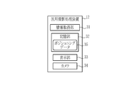
- the medical imaging processing device 12 includes an information acquisition unit 31, a storage unit 32, a display unit 33, and a camera 34.
- the medical imaging processing device 12 includes an information acquisition unit 31, a storage unit 32, a determination unit 201 (see FIG. 10), a control unit 202 (see FIG. 10), a subject detection unit 301 (see FIG. 11), and a positioning data generation unit 302. (See FIG. 11) and a program related to the display control unit 305 (see FIG. 12) and the like are incorporated in the memory (not shown).
- the program is operated by a comprehensive control unit (not shown) composed of a processor, the information acquisition unit 31, the storage unit 32, the determination unit 201 (see FIG. 10), the control unit 202 (see FIG. 10), and the subject.
- Functions such as a detection unit 301 (see FIG. 11), a positioning data generation unit 302 (see FIG. 11), and a display control unit 305 (see FIG. 12) are realized.
- the information acquisition unit 31 directly or indirectly connects to the console 20, for example, subject information that identifies the subject Obj such as the name or ID (identifier) and physique (for example, the size and thickness of the imaging portion).
- subject information that identifies the subject Obj such as the name or ID (identifier) and physique (for example, the size and thickness of the imaging portion).
- the imaging information regarding the imaging site, the imaging direction, and other imaging modes is acquired.
- the medical imaging processing device 12 cooperates with the imaging unit 11.
- the “photographing site” is a portion of the subject Obj to be imaged, and is, for example, a head, chest, abdomen, thigh, lower leg, wrist joint, knee joint, or the like.
- the “shooting direction” is the direction of the global subject Obj in shooting, such as PA (Posterior-Anterior) or AP (Anterior-Posterior).
- the “other” shooting mode is, for example, a standing position or a lying position, or the overall
- the storage unit 32 stores one or a plurality of positioning data 35.
- the positioning data 35 is information for specifying the arrangement of the subject Obj with respect to the photographing unit 11. Specifically, the positioning data 35 three-dimensionally specifies the position, posture, and shape of the subject Obj when the subject Obj is photographed by using the photographing unit 11. "Specify three-dimensionally" means to specify a relative relationship with a reference object (here, a radiation imaging unit 14) in a three-dimensional space such as an imaging room in which an imaging unit 11 is located. .. In the present embodiment, since the medical imaging processing device 12 cooperates with the radiographic imaging unit 11, the storage unit 32 stereoscopically changes the position, posture, and shape of the subject Obj with respect to the radiographic imaging unit 14. Information for identification is stored as positioning data 35.
- the storage unit 32 stores the positioning data 35 for each subject Obj or for each photographing portion of the subject Obj.
- the storage unit 32 uses the positioning data 35 as the positioning data of the wrist joint, which is one of the imaging parts of the specific subject Obj, and the positioning data of the knee joint, which is one of the other imaging parts of the subject Obj. It stores two types of information. Therefore, the medical imaging processing device 12 can appropriately select and use the positioning data 35 related to the imaging to be performed by using the subject information and the imaging information acquired by the information acquisition unit 31.
- the positioning data 35 is data related to the subject Obj, data related to a subject different from the subject Obj to be photographed, or schematic model data.
- the data related to the subject Obj is data representing the arrangement of the subject Obj with respect to the photographing unit 11 (or the same type of photographing device (a device capable of taking the same shooting form as the photographing unit 11)) in the past shooting. That is, the data related to the subject Obj is information for specifying the position, posture, and shape of the subject Obj itself in the past shooting.
- the data relating to another subject is information for specifying the position, posture, and shape of a person different from the subject Obj, which is the current shooting target, in the past shooting.
- the schematic model data is information that generally determines the ideal position, posture, and shape of the subject Obj, which is not related to the shooting results of a specific subject, and is, for example, three-dimensional by computer graphics. It is a model.
- the data related to the subject Obj and the data related to another subject can be made into a three-dimensional model by computer rafix. In this case, although it is a three-dimensional model, it is data related to the subject Obj and data related to another subject.
- the positioning data 35 is data related to the subject Obj, that is, information for specifying the position, posture, and shape of the subject Obj itself in the past shooting. This is to support the reproduction of the same position, posture, and shape as in the past shooting. Further, in the present embodiment, the positioning data 35 is a three-dimensional model of the position, posture, and shape of the subject Obj in the past shooting (see FIG. 7).
- the positioning data 35 is data related to a subject different from the subject Obj to be photographed or schematic model data, that is, when the subject Obj to be photographed has never taken a picture in the past, that is, Even when the subject Obj takes a picture for the first time, the positioning can be appropriately supported. Therefore, when the positioning data 35 is data relating to another subject, the storage unit 32 stores the positioning data relating to another subject having a shape and size similar to that of the subject Obj in association with the subject Obj. When the positioning data 35 is schematic model data, model data having a shape and size similar to that of the subject Obj is stored in association with the subject Obj.
- “Relate and store” means that the shape and size of the subject Obj are similar to those of the subject Obj by using the subject information and / or the shooting information of the subject Obj to be photographed from the plurality of positioning data 35. It means making it possible to select high data smoothly.
- the display unit 33 When the subject Obj is photographed by the photographing unit 11, the display unit 33 three-dimensionally displays the arrangement of the subject with respect to the photographing unit 11 by using the positioning data 35. Specifically, the display unit 33 displays the arrangement of the subject Obj with respect to the photographing unit 11 in a manner showing the three-dimensional position, posture, and shape of the subject Obj. As a result, the display unit 33 guides the user 25 to arrange the subject Obj, which is the target of positioning.
- the aspect showing the three-dimensional position means an aspect in which the user 25 can recognize the position where the subject Obj should be arranged with respect to the photographing unit 11 from the display contents of the display unit 33.
- the mode showing a three-dimensional posture means a mode in which the user 25 can recognize the relative posture that the subject Obj should take with respect to the photographing unit 11 from the display contents of the display unit 33.
- the mode showing the three-dimensional shape is a mode in which the user 25 can recognize a specific three-dimensional shape (for example, an overall shape such as a bending angle of a joint) to be taken by the subject Obj from the display contents of the display unit 33.
- the display unit 33 displays the three-dimensional shape of the subject Obj in a manner showing the overall shape and also the unevenness of the subject Obj (such as the degree of attachment of muscle or fat). .. This is to enable the user 25 to more accurately recognize the three-dimensional shape of the subject Obj.
- the display unit 33 displays, for example, by projecting a component that serves as a reference for positioning the subject Obj, a display (such as a liquid crystal display device) that displays the subject Obj on the screen, and an arrangement of the subject Obj in the photographing unit 11. It is a projector (projector or the like) or an augmented reality (AR (Augmented Reality)) display that superimposes and recognizes the arrangement of the subject Obj in reality.
- the AR display constituting the display unit 33 is, for example, a see-through type head-mounted display or the like.
- the camera 34 photographs at least a component (here, a radiation photographing unit 14) that serves as a reference in the positioning of the subject Obj and the subject Obj in the photographing unit 11 using visible light, infrared light, or the like.
- the video or image (hereinafter referred to as a camera image) output by the camera 34 may be used by the display unit 33 depending on its specific configuration.
- the display unit 33 is a liquid crystal display device
- the display unit 33 displays the camera image and superimposes it on the camera image to display the arrangement of the subject Obj with respect to the photographing unit 11.
- the camera 34 can move in the direction of the arrow 37 with respect to the shooting unit 11, and the camera 34 can be moved in a plurality of directions while capturing the shooting unit 11 and the subject Obj in the shooting range 38. You can shoot these from.
- the display unit 33 adjusts the display of the arrangement of the subject Obj according to the orientation of the shooting unit 11 captured in the camera image.
- the subject Obj is a wrist joint and a radiographic image of the side surface of the wrist joint is obtained.
- the subject Obj is usually arranged at an angle of about 7 degrees with respect to the radiation photographing unit 14.
- the direction along the side of the radiation photographing unit 14 that directs the longitudinal direction of the subject Obj is the X direction
- the direction along the side of the radiation photographing unit 14 perpendicular to this is the Y direction
- the surface 39 having the subject Obj shown for convenience is approximately 7 in the Y direction with respect to the normal (not shown) of the radiographing unit 14.
- the ideal arrangement of the subject Obj is to incline the degree. This is because when the inclination is ⁇ 5 degrees or more with respect to this angle, the obtained radiographic image of the side surface of the wrist joint is treated as an imaging failure (so-called imaging loss), and reimaging is required.
- imaging loss imaging failure
- the subject Obj when the subject Obj is actually positioned, the subject Obj may deviate from this ideal arrangement. For example, as shown in FIG. 5, when viewed from the X direction, the actual subject Obj may be displaced by an angle ⁇ x (degrees) around the X direction with respect to the ideal arrangement 40 of the subject Obj. If the angle ⁇ x is large, it is clear that the image is lost, and the subject Obj is greatly tilted from the ideal arrangement 40 to some extent, the positioning direction of the subject Obj is clear. However, as described above, since the allowable inclination is as small as less than ⁇ 5 degrees from the ideal arrangement 40, if the subject Obj is positioned with some accuracy and the angle ⁇ x is relatively small, the image may be lost or the image may be lost.
- a positioning judgment it becomes difficult to make a judgment regarding the accuracy of positioning (hereinafter, referred to as a positioning judgment) as to whether or not a radiographic image comparable to a radiographic image taken in the past can be obtained.
- a positioning judgment it becomes difficult to make a judgment regarding the accuracy of positioning (hereinafter, referred to as a positioning judgment) as to whether or not a radiographic image comparable to a radiographic image taken in the past can be obtained.
- the palm ulnar side of the subject Obj is attached to the radiography photographing unit 14, but the actual subject Obj rotates from the ideal arrangement 40 in the Y direction depending on the pressing force thereof. There may be.
- the angle of rotation ⁇ y (degrees) around the Y direction also causes copying loss and the like. Then, when the subject Obj is positioned accurately to some extent and the angle ⁇ y is relatively small, the positioning determination is difficult, and in particular, the positioning determination regarding the angle ⁇ y is difficult even when viewed from the X direction.
- the medical imaging system 10 and the medical imaging processing device 12 use the positioning data 35 on the display unit 33, and the subject Obj with respect to the radiation imaging unit 14 which is the reference of the positioning of the imaging unit 11.
- the ideal arrangement 40 of is displayed three-dimensionally.
- the user 25 can accurately grasp the position, posture, and shape in which the subject Obj should be arranged at a glance. That is, according to the arrangement support display of the display unit 33, not only the position, the posture, or the shape in which the subject Obj should be arranged, but also these can be comprehensively perceived. As a result, even after the subject Obj is positioned accurately to some extent, the positioning determination can be made accurately and the subject Obj can be easily positioned in the ideal arrangement 40.
- the ideal arrangement 40 of the subject Obj is shown by a two-dimensional (planar) display in which the contour 41 of the ideal arrangement 40 is superimposed on the subject Obj viewed from the X and Y directions as in the conventional case.
- the subject Obj may be positioned closer to the ideal arrangement 40 when viewed from the Y direction, and then the subject Obj may deviate from the ideal arrangement 40 when viewed from the X direction again.
- the accurate positioning of the subject Obj is not easy.
- the three-dimensional display of the ideal arrangement 40 on the display unit 33 of the medical imaging system 10 and the medical imaging processing device 12 it is not necessary to individually consider parameters related to a plurality of positionings such as an angle ⁇ x and an angle ⁇ y. Also, the position, posture, and shape in which the subject Obj should be placed can be comprehensively recognized. Therefore, by positioning the subject Obj by looking at the placement support display of the display unit 33, accurate and easy positioning of the subject Obj can be supported.
- the arrangement support display of the display unit 33 shows not only the outline 41 of the subject Obj in the ideal arrangement 40 but also the unevenness thereof by the wire frame 42. Therefore, it is easy to recognize the position, posture, and shape particularly accurately. As a result, the subject Obj can be positioned in the ideal arrangement 40 particularly easily and accurately.
- the subject Obj is a wrist joint
- the subject Obj is arbitrary.
- the knee joint can be the subject Obj.
- the arrangement support display that three-dimensionally displays the ideal arrangement 40 of the display unit 33, even when the subject Obj is a knee joint, the position, posture, and shape in which the subject Obj should be arranged are comprehensively recognized. it can.
- the subject Obj is the knee joint and a radiological image of the side surface of the knee joint is taken (FIG.
- the knee joint portion 51, the thigh portion 52, and the thigh portion 52 are formed around an axis 57 parallel to the side of the radiography unit 14, for example, depending on how the weight is placed or the degree of force. / Or, rotation (twist) of the lower leg portion 53 occurs. That is, the angle ⁇ of rotation around the axis 57 is one of the parameters that determines the success or failure of positioning.
- this angle ⁇ is also used for positioning the subject Obj. It is one of the parameters that determine success or failure.
- the lower leg 53 is usually taken parallel to the side of the radiography unit 14, the angle ⁇ formed by the lower leg 53 and the axis 57 parallel to the side of the radiography unit 14 is also positioned. It is a parameter that determines the success or failure of.
- the subject Obj When the subject Obj is a knee joint, it is necessary to consider a plurality of parameters such as angle ⁇ , angle ⁇ , and angle ⁇ in its positioning as described above, but it is not easy to grasp accurately. Therefore, as in the first embodiment, if the ideal arrangement (not shown) for taking a radiographic image of the side surface of the knee joint is three-dimensionally displayed on the display unit 33, the plurality of parameters are not considered individually. However, the position, posture, and shape in which the knee joint, which is the subject Obj, should be arranged can be comprehensively recognized. As a result, the subject Obj can be easily and accurately positioned in its ideal arrangement. The same applies to joints other than the wrist joint and knee joint, and other subject Obj.
- the display unit 33 may display contour lines or the like instead of the wire frame 42 in the arrangement support display. Further, when the ideal arrangement 40 is displayed by a so-called solid model instead of the wire frame 42, the unevenness of the subject Obj can be shown by the color of the texture.
- the positioning data 35 can include information that three-dimensionally identifies the position and orientation of the radiation source 13 with respect to the radiation photographing unit 14. Similar to the display of the ideal arrangement 40 of the subject Obj, the positioning of the radiation source 13 can be supported by displaying the ideal arrangement of the radiation source 13 on the display unit 33.
- the positioning data 35 is used to display the placement support on the display unit 33, but the positioning data 35 can also be used for other controls.
- the medical imaging processing device 12 may be provided with a determination unit 201 and a control unit 202.
- the determination unit 201 determines the difference between the actual subject Obj and the ideal arrangement 40 of the subject Obj displayed by the display unit 33.
- the difference between the subject Obj and the ideal arrangement 40 is, for example, the distance between the corresponding parts of the subject Obj and the ideal arrangement 40 or the average thereof, the angle formed by the subject Obj and the ideal arrangement 40, or the difference between the subject Obj and the ideal arrangement 40.
- the determination unit 201 can be obtained by calculating the actual position, posture, and shape of the subject Obj using, for example, a plurality of camera images taken from different directions. Further, the determination unit 201 can obtain the position, posture, and shape of the subject Obj in the ideal arrangement 40 from the positioning data 35 used by the display unit 33 for the arrangement support display. Therefore, the determination unit 201 can determine the difference. Further, the determination unit 201 compares the above difference with a predetermined threshold value, and determines that there is a "difference" when the difference is larger than the threshold value and the actual subject Obj and the ideal arrangement 40 deviate from each other.
- the control unit 202 prohibits the photographing unit 11 from taking a picture of the subject Obj.
- "Prohibiting photography” means forcibly hindering the execution of photography even if the user 25 gives an instruction by taking measures such as interlocking the exposure of radiation Ra.
- the positioning data 35 can be used to determine the difference from the ideal arrangement 40. Then, this determination simply and automatically performs the positioning determination performed by the user 25. Therefore, as described above, when the positioning data 35 is determined to be different from the ideal arrangement 40 and the difference is large, if shooting is prohibited, the copying loss can be reduced. As a result, it is possible to prevent unnecessary exposure of the subject Obj due to re-shooting.
- the storage unit 32 stores the positioning data 35, and the positioning data 35 can be generated by the medical imaging processing device 12.
- the medical imaging processing device 12 includes a subject detection unit 301 and a positioning data generation unit 302.
- the subject detecting unit 301 detects the subject Obj with respect to the photographing unit 11 from a plurality of locations. Detecting the subject Obj means obtaining the position, orientation, and shape of the subject Obj with respect to the photographing unit 11, or an image or other information for identifying these.
- the subject detection unit 301 captures, for example, a component (here, a radiation imaging unit 14) that serves as a reference in positioning the subject Obj among the imaging units 11 and the subject Obj using visible light, infrared light, or the like.
- the camera 34 can be used as the subject detection unit 301. In this case, the subject detection unit 301 and the camera 34 are the same thing.
- the positioning data generation unit 302 generates the positioning data 35 using the detection result of the subject detection unit 301. For example, when the positioning data 35 is data related to the subject Obj and is a three-dimensional model, the positioning data generation unit 302 determines the position, orientation, and shape of each part of the subject Obj when the shooting is successful. , The image obtained from the subject detection unit 301 (camera image, etc.) is used for identification, and a three-dimensional model thereof is generated. Then, this is associated with the subject information and the shooting information, and stored in the storage unit 32 as the positioning data 35.
- the medical imaging processing device 12 when the medical imaging processing device 12 itself generates the positioning data 35, it is not necessary to separately generate the positioning data 35 by a three-dimensional model creating device or the like, and the imaging unit 11 that cooperates with the medical imaging processing device 12
- the positioning data 35 can be automatically accumulated only by taking a picture of the subject Obj using the above. As a result, the work load of creating the positioning data 35 of the user 25 and the like can be reduced, and the medical imaging system 10 and the medical imaging processing device 12 are easy to use.
- the medical imaging processing device 12 includes a display unit 33 that three-dimensionally displays the ideal arrangement 40, but the medical imaging processing device Reference numeral 12 can use a display or the like constituting another device or system as the display unit 33.
- the medical imaging processing device 12 can omit the display unit 33 and provide a display control unit 305 in place of the display unit 33.
- the display control unit 305 uses the photographing unit 11 to shoot the subject Obj
- the display control unit 305 uses the positioning data 35 to stereoscopically arrange the subject Obj with respect to the photographing unit 11 on the display unit constituting another device or the like. indicate.
- the display unit 33 of the medical imaging processing device 12 of the third embodiment is replaced with the display control unit 305, so that the configuration of the display unit 33 is omitted from the medical imaging processing device 12, but the first embodiment Similarly, in the medical imaging processing apparatus 12 of the second embodiment, the display unit 33 can be omitted and the display control unit 305 can be provided.
- the medical imaging processing device 12 includes the camera 34, but the medical imaging processing device 12 is another device.
- the cameras constituting the system can be used as the camera 34.
- the configuration of the camera 34 is omitted from the medical imaging processing device 12, and the camera is controlled by a camera control unit (not shown) that controls a camera that constitutes another device or system, or a camera that constitutes another device or system. It can be replaced with a camera image acquisition unit (not shown) that acquires an image.
- the medical imaging processing device 12 automatically moves the camera 34 to take images from a plurality of locations, and obtains a camera image necessary for generating the positioning data 35. It is preferable to provide a camera control unit for obtaining. This is because the positioning data 35 can be automatically generated by automatically obtaining the necessary camera image, and an explicit operation for generating the positioning data 35 becomes unnecessary.
- the configurations of the medical imaging processing device 12, the camera 34, the camera control unit, and the camera acquisition unit can be omitted. This is because other devices or systems are responsible for these functions.
- the camera 34 is movable, but instead of making the camera 34 movable, a plurality of cameras are provided. be able to. In this case, among the plurality of cameras, the required camera is appropriately activated and a camera image is taken.
- the first embodiment, the second embodiment, the third embodiment, and various modifications are arbitrarily (for example, partially) combined to form the medical imaging system 10 and the medical imaging processing device 12. Can be done.
- the hardware structure of a processing unit that executes various processes such as an information acquisition unit 31, a determination unit 201, a control unit 202, a positioning data generation unit 302, and a display control unit 305.
- processors include CPU (Central Processing Unit), GPU (Graphical Processing Unit), FPGA (Field Programmable Gate Array), which are general-purpose processors that execute software (programs) and function as various processing units.
- Programmable Logic Device PLD
- PLD Programmable Logic Device
- a processing unit may be composed of one of these various processors, or a combination of two or more processors of the same type or different types (for example, a plurality of FPGAs, a combination of a CPU and an FPGA, or a CPU and a CPU. It may be composed of a combination of GPUs, etc.). Further, a plurality of processing units may be configured by one processor. As an example of configuring a plurality of processing units with one processor, first, as represented by a computer such as a client or a server, one processor is configured by a combination of one or more CPUs and software. There is a form in which this processor functions as a plurality of processing units.
- SoC System On Chip
- a processor that realizes the functions of the entire system including a plurality of processing units with one IC (Integrated Circuit) chip is used.
- the various processing units are configured by using one or more of the above-mentioned various processors as a hardware-like structure.
- the hardware structure of these various processors is, more specifically, an electric circuit in the form of a combination of circuit elements such as semiconductor elements.
- the hardware structure of the storage unit is a storage device such as an HDD (hard disk drive) or SSD (solid stage drive).
- Medical imaging system 11 Imaging unit 12 Medical imaging processing device 13 Radiation source 14 Radiation imaging unit 20 Console 21 Display unit 22 Operation unit 23 Image generation unit 25 User 31 Information acquisition unit 32 Storage unit 33 Display unit 34 Camera 35 Positioning data 37 Arrow 38 Shooting range 39 Surface 40 Ideal arrangement 41 Contour 42 Wire frame 51 Knee joint part 52 Thigh part 53 Lower leg part 57 Axis 201 Judgment unit 202 Control unit 301 Subject detection unit 302 Positioning data generation unit 305 Display control unit
Abstract
2次元的な被写体の配置支援表示をする場合と比較して、より正確かつ容易な被写体の位置決めを支援することができる医用撮影システム及び医用撮影処理装置を提供する。 医用撮影システム(10)は、被写体(Obj)を撮影することにより、医用画像または医用画像の生成に用いるデータを得る撮影部(11)と、撮影部(11)に対する被写体(Obj)の配置を特定するポジショニングデータ(35)を記憶するプロセッサと、撮影部(11)を用いて被写体(Obj)を撮影する場合に、ポジショニングデータ(35)を用いて、撮影部(11)に対する被写体(Obj)の配置を立体的に表示する表示部(33)と、を備える。
Description
本発明は、放射線画像等の医用画像を得るための撮影をする医用撮影システム、及び、医用画像の撮影に係る処理をする医用撮影処理装置に関する。
従来、医療分野においては、被写体を撮影して得る画像を用いた診断等が普及している。例えば、X線等の放射線を用いて被写体である患者を撮影した放射線画像は、被写体内を非侵襲的に可視化することができるため、診断等に広く利用されている。
放射線画像等を用いた診断においては、放射線画像等を撮影する撮影部(例えば放射線撮影部)に対する被写体の配置が重要である。同一被写体の経時的な変化の観察、あるいは、過去の症例との比較等のためである。
このため、近年においては、撮影部に対する被写体の位置決めを支援する医用撮影装置が知られている。例えば、歯列または顎骨等を撮影対象とする歯科用X線撮像装置においては、歯列等のX線撮影する際に被写体の顔を光学的に撮影しておき、その後同一被写体について歯列等のX線撮影を撮影する場合に、被写体の顔部分を写すモニタに前回の撮影時の顔の輪郭等を表すゴースト画像を重畳表示することによって、前回撮影時と同様の位置に被写体を位置決めできるように支援する装置が知られている(特許文献1)。
放射線画像等の医用画像の撮影において被写体の位置決めを支援するには、例えば、被写体等の画像または映像に、被写体を配置すべき位置を表示する方法がある。
しかし、被写体等の画像または映像に、単に被写体を配置すべき位置を表示するだけでは、放射線画像等において要求される精度で被写体を位置決めすることが容易でない場合がある。
例えば、膝関節の放射線画像を得る場合、膝関節は屈曲角度及び股関節に対する旋回角度等について複雑に動き得る。このため、撮影部に対する全体的な位置(距離)等だけでなく、さらにこれら複数のパラメータに関連する配置を総合的に正確に定めて撮影を行う必要がある。この場合、上記のような2次元的な配置支援表示では、これらの複数のパラメータに関連する膝関節の立体的(3次元的)な配置を正確に把握することが難しい。
また、膝関節の正面と側面等、2方向について2次元的な配置支援表示を行うことで原理的には被写体の理想的な立体的配置を得ることができる。しかし、2方向について2次元的な配置支援表示は、2方向の2次元的な配置支援表示を複合的に勘案する必要があるので、依然として、膝関節の立体的(3次元的)な配置を正確に把握することは容易でない。
そこで、本発明は、2次元的な被写体の配置支援表示をする場合と比較して、より正確かつ容易な被写体の位置決めを支援することができる医用撮影システム及び医用撮影処理装置を提供することを目的とする。
本発明の医用撮影システムは、被写体を撮影することにより、医用画像または医用画像の生成に用いるデータを得る撮影部と、撮影部に対する被写体の配置を特定するポジショニングデータを記憶するプロセッサと、撮影部を用いて被写体を撮影する場合に、ポジショニングデータを用いて、撮影部に対する被写体の配置を立体的に表示する表示部と、を備える。
ポジショニングデータは、被写体の位置、姿勢、及び、形状を立体的に特定することが好ましい。
ポジショニングデータは、被写体に係るデータ、被写体とは別の被写体に係るデータ、または、模式的なモデルデータであることが好ましい。
ポジショニングデータが被写体に係るデータである場合、ポジショニングデータは、過去の撮影における撮影部に対する被写体の配置を表すデータであることが好ましい。
ポジショニングデータが別の被写体に係るデータである場合、プロセッサは、被写体と形状及び大きさが類似する別の被写体に係る前記ポジショニングデータを、被写体と関連付けて記憶することが好ましい。
表示部は、被写体の立体的な位置、姿勢、及び、形状を示す態様で被写体の配置を表示することが好ましい。
表示部は、被写体の立体的な形状を被写体の凹凸を示す態様で表示することが好ましい。
プロセッサは、被写体と、表示部が表示する被写体の配置と、の差異を判定し、差異があると判定した場合に、撮影部による被写体の撮影を禁止することが好ましい。
プロセッサは、被写体と表示部が表示する被写体の配置との距離、角度、または、体積を用いて差異を判定することが好ましい。
プロセッサは、撮影部を用いて被写体を撮影する場合に、撮影部に対する被写体を複数箇所から検出し、検出結果を用いてポジショニングデータを生成することが好ましい。
本発明の医用撮影処理装置は、プロセッサを備える医用撮影処理装置であって、プロセッサは、医用画像または医用画像の生成に用いるデータを得る撮影部に対する被写体の配置を特定するポジショニングデータを生成し、撮影部を用いて被写体を撮影する場合に、ポジショニングデータを用いて、撮影部に対する被写体の配置を表示部に立体的に表示する。
本発明の医用撮影システム及び医用撮影処理装置によれば、2次元的な被写体の配置支援表示をする場合と比較して、より正確かつ容易な被写体の位置決めを支援することができる。
[第1実施形態]
図1に示すように、医用撮影システム10は、撮影部11と、医用撮影処理装置12と、を備える。
図1に示すように、医用撮影システム10は、撮影部11と、医用撮影処理装置12と、を備える。
撮影部11は、被写体Objを撮影することにより、医用画像または医用画像の生成に用いるデータ(以下、医用画像等という)を得る。医用画像とは、医学的な観察、検査及び/または診断等に使用する画像であり、例えば、X線等の放射線を用いて被写体Objを撮影して得る放射線画像である。医用画像の生成に用いるデータとは、例えば、断層画像の生成に利用する撮影データである。すなわち、医用画像の生成に用いるデータとは、診断等に使用する医用画像が単純な撮影によって直接的に得られない場合に、その医用画像を得るために取得する前駆的な画像その他のデータである。
撮影部11は、被写体Objをポジショニングして撮影することにより医用画像等を得る任意の装置を用いて構成することができる。例えば、撮影部11は、X線その他の放射線を用いて被写体Objを撮影する放射線撮影装置である。
被写体Objのポジショニングとは、撮影部11を構成する1または複数の特定の物(以下、単に「撮影部11」という)に対する被写体Objの位置を調整し、位置決めすることをいい、これらの物に対する被写体Objの姿勢を調整することを含む。被写体Objの姿勢とは、被写体Objの全体または部分の空間的な向きを決定する角度に関する情報をいい、被写体Objの全体または部分が変形し得る場合には被写体Objが特定の形状をとっている状態の空間的な向きを決定する角度に関する情報である。
医用撮影処理装置12は、撮影部11を用いた医用画像等の撮影において、撮影部11を操作する医師または技師等の使用者25に、被写体Objのポジショニングに係る情報を提供するための処理をする。これにより、医用撮影処理装置12は、使用者25による被写体Objのポジショニングを支援する。
本実施形態においては、撮影部11は放射線を用いて被写体Objを撮影することにより、被写体Objの透視画像を得る放射線撮影装置である。このため、撮影部11は、放射線源13、放射線撮影部14、及び、コンソール20を備える。
放射線源13は、撮影に必要な放射線Raを発生する装置であり、放射線Raを発生する放射線管と、放射線管が放射線Raを発生するために必要な高電圧を発生する高電圧発生回路等からなる。放射線源13は、放射線管の管電圧及び管電流等を調節することにより、線質(いわゆるエネルギー分布)が異なる複数種類の放射線を発生できる。放射線源13が発生する放射線のエネルギーは撮影条件の1つである。本実施形態においては、放射線源13はX線を発生するX線源である。このため、撮影部11はX線を用いて被写体Objを撮影することにより、被写体ObjのX線画像を取得するX線撮影装置である。被写体Objは例えば人体または人体の部分である。放射線源13は、放射線Raを受ける放射線撮影部14に対して位置調整をする。少なくとも放射線源13と放射線撮影部14との相対的な位置関係に関して、診断等に使用可能な適切な放射線画像を得るためである。
放射線撮影部14は、放射線源13が発生した放射線Raを用いて被写体Objを撮影する。このため、放射線撮影部14は、放射線Raを用いて被写体Objを撮影する1または複数の放射線検出パネルを有する。放射線撮影部14はいわゆるFPD(Flat Panel Detector)である。このため、放射線撮影部14は、放射線検出パネルによって被写体Objを透過した放射線Raを検出して電気信号に変換することにより、被写体Objの放射線画像を出力する。この放射線画像は医用画像の1つである。放射線撮影部14を用いた撮影においては、必要に応じてグリッド(図示しない)を併用できる。グリッドは、放射線の散乱線成分を除去する装置であり、例えば、静止型のリスホルムブレンデ、または、移動型のブッキーブレンデ等である。被写体Objは放射線撮影部14に対してポジショニングをする。被写体Objまたは撮影対象である被写体Objの部分について、診断等に使用可能な適切な放射線画像を得るためである。
コンソール20は、放射線源13及び放射線撮影部14等の動作を制御する制御装置(コンピュータ)であり、表示部21、操作部22、及び、画像生成部23等を備える。表示部21は、例えば液晶ディスプレイ等であり、撮影した長尺放射線画像その他の放射線画像の表示、及び、その他操作または設定等に係る必要な表示をする。操作部22は、撮影条件等の設定入力、放射線源13及び放射線撮影部14の操作に用いる、例えばキーボード及び/またはポインティングデバイス等である。表示部21及び操作部22はタッチパネルで構成することができる。画像生成部23は、放射線撮影部14の出力を用いて放射線画像を生成する。
図2に示すように、医用撮影処理装置12は、情報取得部31、記憶部32、表示部33、及び、カメラ34を備える。医用撮影処理装置12には、情報取得部31、記憶部32、判定部201(図10参照)、制御部202(図10参照)、被写体検出部301(図11参照)、ポジショニングデータ生成部302(図11参照)、及び表示制御部305(図12参照)等に関するプログラムがメモリ(図示せず)に組み込まれている。プロセッサによって構成される総合制御部(図示せず)によってそのプログラムが動作することで、情報取得部31、記憶部32、判定部201(図10参照)、制御部202(図10参照)、被写体検出部301(図11参照)、ポジショニングデータ生成部302(図11参照)、及び表示制御部305(図12参照)等の機能が実現する。
情報取得部31は、例えば、コンソール20に直接的または間接的に接続し、氏名もしくはID(identifier)及び体格(例えば撮影部位の大きさ及び厚さ等)等の被写体Objを特定する被写体情報、並びに、撮影部位、撮影方向、及びその他撮影形態に関する撮影情報を取得する。これにより、医用撮影処理装置12は、撮影部11と連携する。「撮影部位」とは、撮影対象とする被写体Objの部分であり、例えば、頭部、胸部、腹部、大腿部、下腿部、手関節、または、膝関節等である。「撮影方向」とは、PA(Posterior-Anterior)またはAP(Anterior-Posterior)等、撮影における大局的な被写体Objの向きである。「その他」の撮影形態とは、例えば立位または臥位等、撮影における被写体Objの大局的な姿勢及び/または形状等である。
記憶部32は、1または複数のポジショニングデータ35を記憶する。ポジショニングデータ35とは、撮影部11に対する被写体Objの配置を特定する情報である。ポジショニングデータ35は、具体的には、撮影部11を用いて被写体Objを撮影する場合の被写体Objの位置、姿勢、及び、形状を立体的に特定する。「立体的に特定する」とは、撮影部11がある撮影室等の3次元空間において、撮影時に基準となる物(ここでは放射線撮影部14)との相対的な関係を特定することをいう。本実施形態においては、医用撮影処理装置12は、放射線撮影装置である撮影部11と連携するので、記憶部32は、放射線撮影部14に対する被写体Objの位置、姿勢、及び、形状を立体的に特定するための情報をポジショニングデータ35として記憶している。
記憶部32は、被写体Objごとに、または、被写体Objの撮影部位ごとに、ポジショニングデータ35を記憶している。例えば、記憶部32は、ポジショニングデータ35として、特定の被写体Objの撮影部位の1つである手関節のポジショニングデータと、その被写体Objの別の撮影部位の1つである膝関節のポジショニングデータの2種類の情報を記憶している。このため、医用撮影処理装置12は、情報取得部31が取得した被写体情報及び撮影情報を用いて、実施をする撮影に関連するポジショニングデータ35を適宜選択して使用できる。
また、ポジショニングデータ35は、被写体Objに係るデータ、撮影対象である被写体Objとは別の被写体に係るデータ、または、模式的なモデルデータである。被写体Objに係るデータとは、過去の撮影における撮影部11(またはこれと同種の撮影装置(撮影部11と同じ撮影形態をとり得る装置))に対する被写体Objの配置を表すデータである。すなわち、被写体Objに係るデータとは、過去の撮影における被写体Obj自身の位置、姿勢、及び、形状を特定する情報である。別の被写体に関するデータとは、現在の撮影対象である被写体Objとは別人の過去の撮影における位置、姿勢、及び、形状を特定する情報である。模式的なモデルデータとは、特定の被写体の撮影実績には関連せず、被写体Objの理想的な位置、姿勢、及び、形状を一般的に定める情報であり、例えば、コンピュータグラフィックスによる3次元モデルである。なお、被写体Objに係るデータ、及び、別の被写体に係るデータは、コンピュータラフィックスによる3次元モデルにしておくことができる。この場合、3次元モデルであるが、被写体Objに係るデータ、及び、別の被写体に係るデータである。
本実施形態においては、ポジショニングデータ35は、被写体Objに係るデータ、すなわち、過去の撮影における被写体Obj自身の位置、姿勢、及び、形状を特定する情報である。過去の撮影と同じ位置、姿勢、及び、形状の再現を支援するためである。また、本実施形態においては、ポジショニングデータ35は、過去の撮影における被写体Objの位置、姿勢、及び、形状を、3次元モデルにしたものである(図7参照)。
ポジショニングデータ35が、撮影対象である被写体Objとは別の被写体に関するデータ、または、模式的なモデルデータである場合、撮影対象である被写体Objが過去の撮影を行ったことがない場合に、すなわち被写体Objが初めて撮影をする場合においても、そのポジショニングを適切に支援できる。そのために、ポジショニングデータ35が別の被写体に係るデータである場合、記憶部32は、被写体Objと形状及び大きさが類似する別の被写体に係るポジショニングデータを、被写体Objと関連付けて記憶する。また、ポジショニングデータ35が模式的なモデルデータである場合には、被写体Objと形状及び大きさが類似するモデルデータを、被写体Objと関連付けて記憶する。「関連付けて記憶する」とは、複数のポジショニングデータ35の中から、撮影を実施する被写体Objの被写体情報及び/または撮影情報を用いて、被写体Objと形状及び大きさが類似する等関連性が高いデータを円滑に選択できる状態にすることをいう。
表示部33は、撮影部11を用いて被写体Objを撮影する場合に、ポジショニングデータ35を用いて、撮影部11に対する被写体の配置を立体的に表示する。具体的には、表示部33は、被写体Objの立体的な位置、姿勢、及び、形状を示す態様で、撮影部11に対する被写体Objの配置を表示する。これにより、表示部33は、ポジショニングの目標となる被写体Objの配置を使用者25に案内する。
立体的な位置を示す態様とは、撮影部11に対して被写体Objを配置すべき位置を、使用者25が表示部33の表示内容から認識できる態様をいう。立体的な姿勢を示す態様とは、撮影部11に対して被写体Objがとるべき相対的な姿勢を、使用者25が表示部33の表示内容から認識できる態様をいう。立体的な形状を示す態様とは、被写体Objがとるべき特定の3次元的形状(例えば関節の曲がり角等の全体的な形状)を、使用者25が表示部33の表示内容から認識できる態様をいう。特に、本実施形態においては、表示部33は、被写体Objの立体的な形状を、全体的な形状を示す他、さらに被写体Objの凹凸(筋肉または脂肪等付き具合等)を示す態様で表示する。使用者25が、被写体Objの立体的形状を、より正確に認識できるようにするためである。
表示部33は、例えば、撮影部11のうち被写体Objのポジショニングの基準となる構成物及び被写体Objを画面内に表示するディスプレイ(液晶表示装置等)、被写体Objの配置を投影することにより表示する投影機(プロジェクタ等)、または、被写体Objの配置を現実に重畳して認識させる拡張現実(AR(Augmented Reality))ディスプレイ等である。表示部33を構成するARディスプレイは、例えば、シースルー型のヘッドマウントディスプレイ等である。
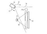
カメラ34は、撮影部11のうち少なくとも被写体Objのポジショニングにおいて基準となる構成物(ここでは放射線撮影部14)と、被写体Objと、を可視光または赤外光等を用いて撮影する。カメラ34が出力する映像または画像(以下、カメラ画像という)は、表示部33が、その具体的構成によって使用する場合がある。例えば、表示部33が液晶表示装置である場合、表示部33はカメラ画像を表示し、かつ、カメラ画像に重畳して撮影部11に対する被写体Objの配置を表示する。
また、図3に示すように、カメラ34は、撮影部11に対して例えば矢印37の方向に移動可能となっており、撮影範囲38に撮影部11及び被写体Objを捉えたまま、複数の方向からこれらを撮影することができる。カメラ34の撮影方向を変更した場合、カメラ画像における撮影部11及び被写体Objの向き等が変わる。このため、表示部33は、カメラ画像に写る撮影部11の向きに合わせて、被写体Objの配置の表示を調整する。
以下、上記のように構成する医用撮影システム10及び医用撮影処理装置12の作用を説明する。図4に示すように、例えば、被写体Objが手関節であり、手関節側面の放射線画像を得るとする。この場合、被写体Objは、通常は、放射線撮影部14に対して約7度傾斜して配置する。被写体Objの長手方向を向ける放射線撮影部14の辺に沿った方向をX方向とし、これに垂直な放射線撮影部14の辺に沿った方向をY方向とし、かつ、X方向及びY方向に垂直な方向(放射線撮影部14の法線方向)をZ方向とすれば、便宜的に示す被写体Objがある面39を、放射線撮影部14の法線(図示しない)に対してY方向に約7度傾斜させるのが理想的な被写体Objの配置である。この角度を基準として、±5度以上の傾斜である場合、得られた手関節側面の放射線画像は撮影失敗(いわゆる写損)として扱われ、再撮影が必要となるからである。また、過去に同じ被写体Objの撮影を行っている場合、その過去の撮影においても上記のように撮影を行っているため、過去の撮影において得た放射線画像との適正に比較し得るようにするためにも、上記基準を遵守する必要がある。さらに、写損にならない範囲内において、新たに撮影する放射線画像は、過去の撮影とできる限り同じ位置、姿勢、及び、形状で撮影することが望ましい。過去の撮影において得た放射線画像との特に正確に比較し得るようにするためである。
しかし、現実に被写体Objをポジショニングする場合、この理想的な配置から被写体Objがずれる場合がある。例えば、図5に示すように、X方向から見ると、被写体Objの理想配置40を基準として、現実の被写体ObjがX方向の回りに角度θx(度)ずれている場合がある。角度θxが大きく、写損になることが明白である程度に被写体Objが理想配置40から大きく傾いていれば、被写体Objのポジショニングの方向性は明らかである。しかし、上述の通り、許容できる傾斜は理想配置40から±5度未満とわずかであるから、被写体Objをある程度正確にポジショニングし、角度θxが比較的小さい場合には、写損になるか、あるいは、過去に撮影した放射線画像と比較し得る放射線画像が得られるかのポジショニングの正確性に係る判断(以下、ポジショニング判断という)をすることが難しくなる。特に、Y方向から被写体Objを見ると、角度θxが比較的小さい場合には、理想配置40と現実の被写体Objの高さ(Z方向の長さ)の差ΔZはほとんど認識し得ない。このため、被写体ObjをY方向から見ても、ポジショニング判断は困難である。
また、図6に示すように、被写体Objの手掌尺側を放射線撮影部14につけるが、その押し当て加減等によっては、現実の被写体Objは理想配置40からY方向の回りに、回転している場合がある。このY方向の周りの回転の角度θy(度)も写損等の原因となる。そして、被写体Objをある程度正確にポジショニングし、角度θyが比較的小さい場合にはポジショニング判断は難しく、特に、X方向から見ても角度θyに関するポジショニング判断は困難である。
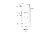
そこで、医用撮影システム10及び医用撮影処理装置12は、図7に示すように、表示部33に、ポジショニングデータ35を用いて、撮影部11のうちポジショニングの基準となる放射線撮影部14に対する被写体Objの理想配置40を立体的に表示する。この表示部33による配置支援表示によれば、使用者25は、被写体Objを配置すべき位置、姿勢、及び、形状を一見して正確に把握できる。すなわち、表示部33の配置支援表示によれば、被写体Objを配置すべき位置、姿勢、または、形状のいずれかだけなく、これらを総合的に感得できる。その結果、被写体Objをある程度正確にポジショニングした後であっても、ポジショニング判断を正確に行い、被写体Objを容易に理想配置40にポジショニングすることができる。
例えば、従来のようにX方向及びY方向からみた被写体Objに理想配置40の輪郭41を重畳する2次元的(平面的)な表示によって被写体Objの理想配置40を示す場合を考えると、X方向からみて被写体Objを理想配置40に近づけてポジショニングした後、Y方向からみるとずれある場合がある。そして、これを勘案してさらにY方向からみて被写体Objを理想配置40に近づけてポジショニングした後、再びX方向からみると、被写体Objが理想配置40からずれている場合がある。このため、従来の2次元的な理想配置40の提示方法では、理想配置40を感得し得るだけの情報が含まれているにもかかわらず、被写体Objの正確なポジショニングは容易でない。これに対し、医用撮影システム10及び医用撮影処理装置12の表示部33における理想配置40の立体的表示によれば、角度θx及び角度θy等の複数のポジショニングに係るパラメータを個別に意識しなくても、被写体Objを配置すべき位置、姿勢、及び、形状について総合的に認識できる。このため、表示部33の配置支援表示をみて被写体Objをポジショニングすることで、正確かつ容易な被写体Objの位置決めを支援することができる。
また、表示部33の配置支援表示は、ワイヤフレーム42により、理想配置40における被写体Objの輪郭41だけでなく、その凹凸をも示す。このため、位置、姿勢、及び、形状を特に正確に認識しやすい。その結果、特に容易かつ正確に被写体Objを理想配置40にポジショニングすることができる。
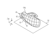
上記第1実施形態においては、被写体Objが手関節である場合を例に挙げたが、被写体Objは任意である。例えば、図8に示すように、膝関節を被写体Objとすることができる。そして、表示部33の理想配置40を立体的に表示する配置支援表示によれば、被写体Objが膝関節である場合も、被写体Objを配置すべき位置、姿勢、及び、形状について総合的に認識できる。具体的には、被写体Objが膝関節であり、かつ、膝関節側面の放射線画像を撮影する場合(図8)、膝関節部分51の他、膝関節部分51の前後に続く大腿部52及び下腿部53を放射線撮影部14に当接して撮影を行う。このように被写体Objをポジショニングする場合、体重ののせ方あるいは力み具合等によって、例えば、放射線撮影部14の辺に平行は平行な軸57の周りに膝関節部分51、大腿部52、及び/または、下腿部53の回転(ひねり)が生じる。すなわち、軸57まわりの回転の角度αがポジショニングの成否を決めるパラメータの1つである。
また、図9に示すように、膝関節部分51の骨及び軟骨等の位置関係は、大腿部52及び下腿部53のなす角度βによって変化するので、この角度βも被写体Objのポジショニングの成否を決めるパラメータの1つである。さらに、通常は、下腿部53を放射線撮影部14の辺に平行にして撮影を実施するので、下腿部53と放射線撮影部14の辺に平行な軸57とのなす角γも、ポジショニングの成否を決めるパラメータである。
被写体Objが膝関節である場合、そのポジショニングにおいては上記のように角度α、角度β、及び、角度γ等の複数のパラメータを考慮しなければならないが、正確に把握することは容易でない。そこで、上記第1実施形態と同様に、表示部33に膝関節側面の放射線画像を撮影する場合の理想配置(図示しない)を立体的に表示すれば、上記複数のパラメータを個別に考慮しなくても、被写体Objである膝関節を配置すべき位置、姿勢、及び、形状を総合的に認識できる。その結果、容易かつ正確に被写体Objをその理想配置にポジショニングすることができる。手関節及び膝関節以外の関節、その他の被写体Objについても同様である。
なお、上記第1実施形態においては、表示部33は上記配置支援表示において、ワイヤフレーム42の代わりに等高線等を表示してもよい。また、ワイヤフレーム42の代わりに、理想配置40をいわゆるソリッドモデルで表示する場合にはテクスチャの色彩によって被写体Objの凹凸を示すことができる。
また、ポジショニングデータ35は、放射線撮影部14に対する放射線源13の位置及び姿勢を立体的に特定する情報を含むことができる。被写体Objの理想配置40の表示と同様に、表示部33に放射線源13の理想配置を表示することにより、放射線源13の位置決めを支援することができる。
[第2実施形態]
上記第1実施形態においては、ポジショニングデータ35を用いて表示部33における配置支援表示をしているが、ポジショニングデータ35は他の制御にも使用できる。例えば、図10に示すように、医用撮影処理装置12には、判定部201及び制御部202を設けることができる。
上記第1実施形態においては、ポジショニングデータ35を用いて表示部33における配置支援表示をしているが、ポジショニングデータ35は他の制御にも使用できる。例えば、図10に示すように、医用撮影処理装置12には、判定部201及び制御部202を設けることができる。
判定部201は、実際の被写体Objと、表示部33が表示する被写体Objの理想配置40と、の差異を判定する。被写体Objと理想配置40との差異とは、例えば、被写体Objと理想配置40の対応する部分間の距離もしくはその平均等、被写体Objと理想配置40がなす角度、または、被写体Objと理想配置40の重複する部分(あるいは重複しない部分)の体積、等である。したがって、判定部201は、被写体Objと、表示部33が表示する被写体Objの理想配置40との距離、角度、及び/または、体積を用いて上記差異を判定する。判定部201は、例えば異なる方向から撮影した複数のカメラ画像を用いて実際の被写体Objの位置、姿勢、及び、形状を算出等して得ることができる。また、判定部201は、表示部33が配置支援表示に使用するポジショニングデータ35から、理想配置40における被写体Objの位置、姿勢、及び、形状を得ることができる。したがって、判定部201は、上記差異の判定をすることができる。また、判定部201は、例えば、上記差異を所定の閾値と比較し、差異が閾値よりも大きく、実際の被写体Objと理想配置40が乖離している場合に「差異がある」と判定する。
制御部202は、判定部201が「差異がある」と判定した場合に、撮影部11による被写体Objの撮影を禁止する。「撮影を禁止する」とは、放射線Raの曝射をインターロックする等の処置により、使用者25の指示があったとしても、強制的に撮影の実行を妨げることをいう。
上記のように、ポジショニングデータ35は、理想配置40との差異の判定に使用できる。そして、この判定は、使用者25が行うポジショニング判断を簡易的かつ自動的に行うものである。したがって、上記のように、ポジショニングデータ35を理想配置40からの差異の判定の結果、差異が大きい場合に、撮影を禁止すれば、写損を低減できる。その結果、再撮影による被写体Objの無駄な被曝を防ぐことができる。
[第3実施形態]
上記第1実施形態及び第2実施形態においては、記憶部32がポジショニングデータ35を記憶しているが、ポジショニングデータ35は、医用撮影処理装置12が生成することができる。この場合、図11に示すように、医用撮影処理装置12は、被写体検出部301と、ポジショニングデータ生成部302と、を備える。
上記第1実施形態及び第2実施形態においては、記憶部32がポジショニングデータ35を記憶しているが、ポジショニングデータ35は、医用撮影処理装置12が生成することができる。この場合、図11に示すように、医用撮影処理装置12は、被写体検出部301と、ポジショニングデータ生成部302と、を備える。
被写体検出部301は、撮影部11を用いて被写体Objを撮影する場合に、撮影部11に対する被写体Objを複数箇所から検出する。被写体Objについて検出とは、撮影部11に対する被写体Objの位置、姿勢、及び、形状、または、これらを特定するための画像その他の情報を得ることをいう。被写体検出部301は、例えば、撮影部11のうち少なくとも被写体Objのポジショニングにおいて基準となる構成物(ここでは放射線撮影部14)と、被写体Objと、を可視光または赤外光等を用いて撮影するカメラ、放射線撮影部14の撮影面に備える圧力センサ、赤外光の飛行時間によって距離を計測するTOF(Time of Flight)カメラ、その他距離等の計測器のいずれか、または組み合わせである。なお、カメラ34を被写体検出部301として使用することができる。この場合、被写体検出部301とカメラ34は同一の物である。
ポジショニングデータ生成部302は、被写体検出部301の検出結果を用いてポジショニングデータ35を生成する。例えば、ポジショニングデータ35が、被写体Objに係るデータであって、かつ3次元モデルである場合、ポジショニングデータ生成部302は、撮影が成功した場合の被写体Objの各部の位置、姿勢、及び、形状を、被写体検出部301から得る画像等(カメラ画像等)を用いて特定し、その3次元モデルを生成する。そして、これを被写体情報及び撮影情報と関連付け、ポジショニングデータ35として記憶部32に記憶する。
上記のように、医用撮影処理装置12自身がポジショニングデータ35を生成する場合、3次元モデル作成装置等によって別途にポジショニングデータ35を生成する必要がなく、医用撮影処理装置12と連携する撮影部11を用いて被写体Objの撮影をするだけで、自動的にポジショニングデータ35を蓄積することができる。その結果、使用者25等のポジショニングデータ35を作成する作業負担を削減でき、医用撮影システム10及び医用撮影処理装置12の使い勝手が良い。
なお、上記第1実施形態、第2実施形態、及び、第3実施形態においては、医用撮影処理装置12は理想配置40を立体的に表示する表示部33を含んでいるが、医用撮影処理装置12は他の装置またはシステムを構成するディスプレイ等を表示部33として使用できる。この場合、図12に示すように、医用撮影処理装置12は表示部33を省略し、表示部33の代わりに、表示制御部305を設けることができる。表示制御部305は、撮影部11を用いて被写体Objを撮影する場合に、ポジショニングデータ35を用いて、撮影部11に対する被写体Objの配置を、他の装置等を構成する表示部に立体的に表示する。この例では、第3実施形態の医用撮影処理装置12の表示部33を表示制御部305に置き換えることにより、医用撮影処理装置12から表示部33の構成を省略しているが、第1実施形態及び第2実施形態の医用撮影処理装置12においても同様に表示部33を省略し、表示制御部305を設けることができる。
また、上記第1位実施形態、第2実施形態、第3実施形態、及び各種変形例においては、医用撮影処理装置12は、カメラ34を含んでいるが、医用撮影処理装置12は他の装置またはシステムを構成するカメラをカメラ34として使用できる。この場合、医用撮影処理装置12からカメラ34の構成を省略し、他の装置またはシステムを構成するカメラを制御するカメラ制御部(図示しない)、または、他の装置またはシステムを構成するカメラからカメラ画像を取得するカメラ画像取得部(図示しない)に置き換えることができる。例えば、被写体検出部301をカメラ34で構成する場合には、医用撮影処理装置12は、カメラ34を自動的に移動して複数箇所から撮影をし、ポジショニングデータ35の生成に必要なカメラ画像を得るカメラ制御部を設けることが好ましい。自動的に必要なカメラ画像を得ることで、ポジショニングデータ35を自動的に生成でき、ポジショニングデータ35を生成するための明示的な操作が不要となるからである。特に、他の装置またはシステムを構成するカメラ及び表示部を流用する場合、医用撮影処理装置12からカメラ34、上記カメラ制御部、及び、上記カメラ取得部の構成を省略することができる。他の装置またはシステムがこれらの機能を担うからである。
なお、上記第1位実施形態、第2実施形態、第3実施形態、及び各種変形例においては、カメラ34が移動可能であるが、カメラ34を移動可能にする代わりに、複数のカメラを設けることができる。この場合、複数のカメラのうち、必要になったカメラを適宜起動し、カメラ画像を撮影する。
なお、上記第1位実施形態、第2実施形態、第3実施形態、及び各種変形例は、任意に(例えば部分的に)組み合わせて、医用撮影システム10及び医用撮影処理装置12を構成することができる。
上記実施形態等において、情報取得部31、判定部201、制御部202、ポジショニングデータ生成部302、及び、表示制御部305といった各種の処理を実行する処理部(processing unit)のハードウェア的な構造は、次に示すような各種のプロセッサ(processor)である。各種のプロセッサには、ソフトウエア(プログラム)を実行して各種の処理部として機能する汎用的なプロセッサであるCPU(Central Processing Unit)、GPU(Graphical Processing Unit)、FPGA (Field Programmable Gate Array) などの製造後に回路構成を変更可能なプロセッサであるプログラマブルロジックデバイス(Programmable Logic Device:PLD)、各種の処理を実行するために専用に設計された回路構成を有するプロセッサである専用電気回路などが含まれる。
1つの処理部は、これら各種のプロセッサのうちの1つで構成されてもよいし、同種または異種の2つ以上のプロセッサの組み合せ(例えば、複数のFPGA、CPUとFPGAの組み合わせ、またはCPUとGPUの組み合わせ等)で構成されてもよい。また、複数の処理部を1つのプロセッサで構成してもよい。複数の処理部を1つのプロセッサで構成する例としては、第1に、クライアントやサーバなどのコンピュータに代表されるように、1つ以上のCPUとソフトウエアの組み合わせで1つのプロセッサを構成し、このプロセッサが複数の処理部として機能する形態がある。第2に、システムオンチップ(System On Chip:SoC)などに代表されるように、複数の処理部を含むシステム全体の機能を1つのIC(Integrated Circuit)チップで実現するプロセッサを使用する形態がある。このように、各種の処理部は、ハードウェア的な構造として、上記各種のプロセッサを1つ以上用いて構成される。
さらに、これらの各種のプロセッサのハードウェア的な構造は、より具体的には、半導体素子などの回路素子を組み合わせた形態の電気回路(circuitry)である。また、記憶部のハードウェア的な構造はHDD(hard disc drive)やSSD(solid stage drive)等の記憶装置である。
10 医用撮影システム
11 撮影部
12 医用撮影処理装置
13 放射線源
14 放射線撮影部
20 コンソール
21 表示部
22 操作部
23 画像生成部
25 使用者
31 情報取得部
32 記憶部
33 表示部
34 カメラ
35 ポジショニングデータ
37 矢印
38 撮影範囲
39 面
40 理想配置
41 輪郭
42 ワイヤフレーム
51 膝関節部分
52 大腿部
53 下腿部
57 軸
201 判定部
202 制御部
301 被写体検出部
302 ポジショニングデータ生成部
305 表示制御部
11 撮影部
12 医用撮影処理装置
13 放射線源
14 放射線撮影部
20 コンソール
21 表示部
22 操作部
23 画像生成部
25 使用者
31 情報取得部
32 記憶部
33 表示部
34 カメラ
35 ポジショニングデータ
37 矢印
38 撮影範囲
39 面
40 理想配置
41 輪郭
42 ワイヤフレーム
51 膝関節部分
52 大腿部
53 下腿部
57 軸
201 判定部
202 制御部
301 被写体検出部
302 ポジショニングデータ生成部
305 表示制御部
Claims (11)
- 被写体を撮影することにより、医用画像または医用画像の生成に用いるデータを得る撮影部と、
前記撮影部に対する前記被写体の配置を特定するポジショニングデータを記憶するプロセッサと、
前記撮影部を用いて前記被写体を撮影する場合に、前記ポジショニングデータを用いて、前記撮影部に対する前記被写体の配置を立体的に表示する表示部と、
を備える医用撮影システム。 - 前記ポジショニングデータは、前記被写体の位置、姿勢、及び、形状を立体的に特定する請求項1に記載の医用撮影システム。
- 前記ポジショニングデータは、前記被写体に係るデータ、前記被写体とは別の被写体に係るデータ、または、模式的なモデルデータである請求項1または2に記載の医用撮影システム。
- 前記ポジショニングデータが前記被写体に係るデータである場合、前記ポジショニングデータは、過去の撮影における前記撮影部に対する前記被写体の配置を表すデータである請求項3に記載の医用撮影システム。
- 前記ポジショニングデータが前記別の被写体に係るデータである場合、前記プロセッサは、前記被写体と形状及び大きさが類似する前記別の被写体に係る前記ポジショニングデータを、前記被写体と関連付けて記憶する請求項3に記載の医用撮影システム。
- 前記表示部は、前記被写体の立体的な位置、姿勢、及び、形状を示す態様で前記被写体の配置を表示する請求項1ないし5のいずれか1項に記載の医用撮影システム。
- 前記表示部は、前記被写体の立体的な形状を前記被写体の凹凸を示す態様で表示する請求項6に記載の医用撮影システム。
- 前記プロセッサは、前記被写体と、前記表示部が表示する前記被写体の配置と、の差異を判定し、
前記差異があると判定した場合に、前記撮影部による前記被写体の撮影を禁止する請求項1ないし7のいずれか1項に記載の医用撮影システム。 - 前記プロセッサは、前記被写体と前記表示部が表示する前記被写体の配置との距離、角度、または、体積を用いて前記差異を判定する請求項8に記載の医用撮影システム。
- 前記プロセッサは、前記撮影部を用いて前記被写体を撮影する場合に、前記撮影部に対する前記被写体を複数箇所から検出し、
前記検出結果を用いて前記ポジショニングデータを生成する請求項1ないし9のいずれか1項に記載の医用撮影システム。 - プロセッサを備える医用撮影処理装置であって、
前記プロセッサは、
医用画像または医用画像の生成に用いるデータを得る撮影部に対する被写体の配置を特定するポジショニングデータを生成し、
前記撮影部を用いて前記被写体を撮影する場合に、前記ポジショニングデータを用いて、前記撮影部に対する前記被写体の配置を表示部に立体的に表示する医用撮影処理装置。
Priority Applications (4)
| Application Number | Priority Date | Filing Date | Title |
|---|---|---|---|
| JP2021536908A JP7371100B2 (ja) | 2019-07-29 | 2020-07-14 | 医用撮影システム及び医用撮影処理装置 |
| CN202080055505.1A CN114222530A (zh) | 2019-07-29 | 2020-07-14 | 医用摄影系统及医用摄影处理装置 |
| EP20847852.9A EP4005483A4 (en) | 2019-07-29 | 2020-07-14 | MEDICAL PHOTOGRAPHY SYSTEM AND MEDICAL PHOTOGRAPHY PROCESSING DEVICE |
| US17/586,697 US20220151573A1 (en) | 2019-07-29 | 2022-01-27 | Medical imaging system and medical imaging processing apparatus |
Applications Claiming Priority (2)
| Application Number | Priority Date | Filing Date | Title |
|---|---|---|---|
| JP2019138506 | 2019-07-29 | ||
| JP2019-138506 | 2019-07-29 |
Related Child Applications (1)
| Application Number | Title | Priority Date | Filing Date |
|---|---|---|---|
| US17/586,697 Continuation US20220151573A1 (en) | 2019-07-29 | 2022-01-27 | Medical imaging system and medical imaging processing apparatus |
Publications (1)
| Publication Number | Publication Date |
|---|---|
| WO2021020112A1 true WO2021020112A1 (ja) | 2021-02-04 |
Family
ID=74228326
Family Applications (1)
| Application Number | Title | Priority Date | Filing Date |
|---|---|---|---|
| PCT/JP2020/027395 WO2021020112A1 (ja) | 2019-07-29 | 2020-07-14 | 医用撮影システム及び医用撮影処理装置 |
Country Status (5)
| Country | Link |
|---|---|
| US (1) | US20220151573A1 (ja) |
| EP (1) | EP4005483A4 (ja) |
| JP (1) | JP7371100B2 (ja) |
| CN (1) | CN114222530A (ja) |
| WO (1) | WO2021020112A1 (ja) |
Cited By (1)
| Publication number | Priority date | Publication date | Assignee | Title |
|---|---|---|---|---|
| WO2022176813A1 (ja) * | 2021-02-17 | 2022-08-25 | 富士フイルム株式会社 | 学習装置、学習方法、学習装置の作動プログラム、教師データ生成装置、機械学習モデル及び医療用撮影装置 |
Citations (4)
| Publication number | Priority date | Publication date | Assignee | Title |
|---|---|---|---|---|
| JP2010148656A (ja) | 2008-12-25 | 2010-07-08 | Yoshida Dental Mfg Co Ltd | 撮像条件・位置付け支援システムおよび該システムを備えるx線撮像装置 |
| JP2017023326A (ja) * | 2015-07-21 | 2017-02-02 | 株式会社モリタ製作所 | 医療用x線撮影装置 |
| WO2018122451A1 (en) * | 2016-12-30 | 2018-07-05 | Planmeca Oy | Computed tomography and positioning of the anatomy desired to be imaged |
| JP2019033830A (ja) * | 2017-08-10 | 2019-03-07 | 富士フイルム株式会社 | 放射線撮影システムとその作動方法 |
Family Cites Families (1)
| Publication number | Priority date | Publication date | Assignee | Title |
|---|---|---|---|---|
| BR112017002906A2 (pt) | 2015-05-20 | 2017-12-12 | Koninklijke Philips Nv | sistema de orientação, conjunto de imageamento médico, método para orientar o posicionamento de uma anatomia de interesse de um paciente, elemento de programa de computador, e, mídia legível por computador |
-
2020
- 2020-07-14 WO PCT/JP2020/027395 patent/WO2021020112A1/ja unknown
- 2020-07-14 JP JP2021536908A patent/JP7371100B2/ja active Active
- 2020-07-14 EP EP20847852.9A patent/EP4005483A4/en active Pending
- 2020-07-14 CN CN202080055505.1A patent/CN114222530A/zh active Pending
-
2022
- 2022-01-27 US US17/586,697 patent/US20220151573A1/en active Pending
Patent Citations (4)
| Publication number | Priority date | Publication date | Assignee | Title |
|---|---|---|---|---|
| JP2010148656A (ja) | 2008-12-25 | 2010-07-08 | Yoshida Dental Mfg Co Ltd | 撮像条件・位置付け支援システムおよび該システムを備えるx線撮像装置 |
| JP2017023326A (ja) * | 2015-07-21 | 2017-02-02 | 株式会社モリタ製作所 | 医療用x線撮影装置 |
| WO2018122451A1 (en) * | 2016-12-30 | 2018-07-05 | Planmeca Oy | Computed tomography and positioning of the anatomy desired to be imaged |
| JP2019033830A (ja) * | 2017-08-10 | 2019-03-07 | 富士フイルム株式会社 | 放射線撮影システムとその作動方法 |
Cited By (1)
| Publication number | Priority date | Publication date | Assignee | Title |
|---|---|---|---|---|
| WO2022176813A1 (ja) * | 2021-02-17 | 2022-08-25 | 富士フイルム株式会社 | 学習装置、学習方法、学習装置の作動プログラム、教師データ生成装置、機械学習モデル及び医療用撮影装置 |
Also Published As
| Publication number | Publication date |
|---|---|
| CN114222530A (zh) | 2022-03-22 |
| EP4005483A4 (en) | 2022-09-07 |
| EP4005483A1 (en) | 2022-06-01 |
| JP7371100B2 (ja) | 2023-10-30 |
| US20220151573A1 (en) | 2022-05-19 |
| JPWO2021020112A1 (ja) | 2021-02-04 |
Similar Documents
| Publication | Publication Date | Title |
|---|---|---|
| US10610171B2 (en) | Radiography system and method for operating radiography system | |
| US20190000564A1 (en) | System and method for medical imaging | |
| JP6246718B2 (ja) | 画像表示方法及び画像処理装置 | |
| JP5572040B2 (ja) | 放射線撮影装置 | |
| US7436927B2 (en) | Imaging apparatus and method for the operation thereof | |
| US20050165292A1 (en) | Method and apparatus for virtual digital subtraction angiography | |
| JP6466132B2 (ja) | 医用画像処理装置及びx線画像診断装置 | |
| US10974067B2 (en) | Radiation irradiating apparatus and radiation dose management system | |
| JP5437001B2 (ja) | 放射線撮影装置 | |
| KR20190078853A (ko) | 레이저 표적 투영장치 및 그 제어방법, 레이저 표적 투영장치를 포함하는 레이저 수술 유도 시스템 | |
| JP6345468B2 (ja) | 医用画像診断装置 | |
| JP2002136507A (ja) | X線診断装置 | |
| JP2023162419A (ja) | 位置情報取得装置、方法およびプログラム、並びに放射線画像撮影装置 | |
| WO2021020112A1 (ja) | 医用撮影システム及び医用撮影処理装置 | |
| KR100280198B1 (ko) | Ct촬영이가능한x선촬영장치및방법 | |
| US11937965B2 (en) | Radiographic system | |
| JPWO2021020112A5 (ja) | ||
| JP7190950B2 (ja) | 位置情報表示装置、方法およびプログラム、並びに放射線画像撮影装置 | |
| JP6873296B2 (ja) | 画像処理装置、放射線画像撮影システム、画像処理方法、及び画像処理プログラム | |
| JP6760510B2 (ja) | 放射線撮影装置 | |
| JP6874049B2 (ja) | 放射線照射装置及び線量管理システム | |
| EP4162882A1 (en) | Computer-implemented method for positioning a patient for x-ray image recording | |
| JP7348361B2 (ja) | 画像処理装置 | |
| JP2023122538A (ja) | X線撮影装置および撮影位置補正方法 | |
| JP2024034220A (ja) | X線コンピュータ断層撮影装置及び推定方法 |
Legal Events
| Date | Code | Title | Description |
|---|---|---|---|
| 121 | Ep: the epo has been informed by wipo that ep was designated in this application |
Ref document number: 20847852 Country of ref document: EP Kind code of ref document: A1 |
|
| ENP | Entry into the national phase |
Ref document number: 2021536908 Country of ref document: JP Kind code of ref document: A |
|
| NENP | Non-entry into the national phase |
Ref country code: DE |
|
| ENP | Entry into the national phase |
Ref document number: 2020847852 Country of ref document: EP Effective date: 20220228 |