WO2022176331A1 - 作業機の寿命予測システム - Google Patents
作業機の寿命予測システム Download PDFInfo
- Publication number
- WO2022176331A1 WO2022176331A1 PCT/JP2021/045028 JP2021045028W WO2022176331A1 WO 2022176331 A1 WO2022176331 A1 WO 2022176331A1 JP 2021045028 W JP2021045028 W JP 2021045028W WO 2022176331 A1 WO2022176331 A1 WO 2022176331A1
- Authority
- WO
- WIPO (PCT)
- Prior art keywords
- life
- strain
- calculation unit
- life prediction
- work machine
- Prior art date
Links
- 238000004364 calculation method Methods 0.000 claims abstract description 63
- 238000001514 detection method Methods 0.000 claims abstract description 39
- 238000004891 communication Methods 0.000 claims description 30
- 239000003921 oil Substances 0.000 description 16
- 239000010720 hydraulic oil Substances 0.000 description 5
- 238000000034 method Methods 0.000 description 4
- 230000007935 neutral effect Effects 0.000 description 4
- 230000008602 contraction Effects 0.000 description 3
- 238000013135 deep learning Methods 0.000 description 3
- 238000004458 analytical method Methods 0.000 description 2
- 238000013528 artificial neural network Methods 0.000 description 2
- 238000006243 chemical reaction Methods 0.000 description 2
- 238000010586 diagram Methods 0.000 description 2
- 238000006073 displacement reaction Methods 0.000 description 2
- 239000012530 fluid Substances 0.000 description 2
- 239000011159 matrix material Substances 0.000 description 2
- 238000012916 structural analysis Methods 0.000 description 2
- 240000007594 Oryza sativa Species 0.000 description 1
- 235000007164 Oryza sativa Nutrition 0.000 description 1
- 241001417527 Pempheridae Species 0.000 description 1
- 229910000831 Steel Inorganic materials 0.000 description 1
- 238000013473 artificial intelligence Methods 0.000 description 1
- 230000005540 biological transmission Effects 0.000 description 1
- 238000004422 calculation algorithm Methods 0.000 description 1
- 238000004590 computer program Methods 0.000 description 1
- 238000010276 construction Methods 0.000 description 1
- 238000010801 machine learning Methods 0.000 description 1
- 230000000306 recurrent effect Effects 0.000 description 1
- 235000009566 rice Nutrition 0.000 description 1
- 230000011664 signaling Effects 0.000 description 1
- 239000010959 steel Substances 0.000 description 1
Images


Classifications
-
- E—FIXED CONSTRUCTIONS
- E02—HYDRAULIC ENGINEERING; FOUNDATIONS; SOIL SHIFTING
- E02F—DREDGING; SOIL-SHIFTING
- E02F9/00—Component parts of dredgers or soil-shifting machines, not restricted to one of the kinds covered by groups E02F3/00 - E02F7/00
- E02F9/26—Indicating devices
-
- E—FIXED CONSTRUCTIONS
- E02—HYDRAULIC ENGINEERING; FOUNDATIONS; SOIL SHIFTING
- E02F—DREDGING; SOIL-SHIFTING
- E02F9/00—Component parts of dredgers or soil-shifting machines, not restricted to one of the kinds covered by groups E02F3/00 - E02F7/00
- E02F9/20—Drives; Control devices
- E02F9/2025—Particular purposes of control systems not otherwise provided for
- E02F9/2054—Fleet management
-
- E—FIXED CONSTRUCTIONS
- E02—HYDRAULIC ENGINEERING; FOUNDATIONS; SOIL SHIFTING
- E02F—DREDGING; SOIL-SHIFTING
- E02F9/00—Component parts of dredgers or soil-shifting machines, not restricted to one of the kinds covered by groups E02F3/00 - E02F7/00
- E02F9/26—Indicating devices
- E02F9/267—Diagnosing or detecting failure of vehicles
-
- G—PHYSICS
- G01—MEASURING; TESTING
- G01M—TESTING STATIC OR DYNAMIC BALANCE OF MACHINES OR STRUCTURES; TESTING OF STRUCTURES OR APPARATUS, NOT OTHERWISE PROVIDED FOR
- G01M99/00—Subject matter not provided for in other groups of this subclass
-
- E—FIXED CONSTRUCTIONS
- E02—HYDRAULIC ENGINEERING; FOUNDATIONS; SOIL SHIFTING
- E02F—DREDGING; SOIL-SHIFTING
- E02F9/00—Component parts of dredgers or soil-shifting machines, not restricted to one of the kinds covered by groups E02F3/00 - E02F7/00
- E02F9/20—Drives; Control devices
- E02F9/22—Hydraulic or pneumatic drives
- E02F9/2221—Control of flow rate; Load sensing arrangements
- E02F9/2225—Control of flow rate; Load sensing arrangements using pressure-compensating valves
- E02F9/2228—Control of flow rate; Load sensing arrangements using pressure-compensating valves including an electronic controller
-
- E—FIXED CONSTRUCTIONS
- E02—HYDRAULIC ENGINEERING; FOUNDATIONS; SOIL SHIFTING
- E02F—DREDGING; SOIL-SHIFTING
- E02F9/00—Component parts of dredgers or soil-shifting machines, not restricted to one of the kinds covered by groups E02F3/00 - E02F7/00
- E02F9/20—Drives; Control devices
- E02F9/22—Hydraulic or pneumatic drives
- E02F9/2278—Hydraulic circuits
- E02F9/2285—Pilot-operated systems
-
- E—FIXED CONSTRUCTIONS
- E02—HYDRAULIC ENGINEERING; FOUNDATIONS; SOIL SHIFTING
- E02F—DREDGING; SOIL-SHIFTING
- E02F9/00—Component parts of dredgers or soil-shifting machines, not restricted to one of the kinds covered by groups E02F3/00 - E02F7/00
- E02F9/20—Drives; Control devices
- E02F9/22—Hydraulic or pneumatic drives
- E02F9/2278—Hydraulic circuits
- E02F9/2292—Systems with two or more pumps
-
- E—FIXED CONSTRUCTIONS
- E02—HYDRAULIC ENGINEERING; FOUNDATIONS; SOIL SHIFTING
- E02F—DREDGING; SOIL-SHIFTING
- E02F9/00—Component parts of dredgers or soil-shifting machines, not restricted to one of the kinds covered by groups E02F3/00 - E02F7/00
- E02F9/20—Drives; Control devices
- E02F9/22—Hydraulic or pneumatic drives
- E02F9/2278—Hydraulic circuits
- E02F9/2296—Systems with a variable displacement pump
Definitions
- the present invention relates to a work machine life prediction system.
- the work machine operation status capture system disclosed in Patent Document 1 includes transmission means for sending an e-mail to a server about the work status of each part of the work machine, and a computer that can access the server.
- a status acquisition unit that accesses and acquires the operating conditions saved in the server, a display unit that displays the operating conditions acquired by the situation acquiring unit, and automatic failure of the work machine based on the acquired operating conditions.
- a failure estimating unit for estimating systematically.
- a working machine life prediction system includes a working body provided in a machine body, a hydraulic actuator that operates the working body, and operation information when at least one of the working body and the hydraulic actuator operates.
- a work machine life prediction system comprising an operation detection device that detects and a life calculation unit for calculating the life of the life prediction target part from the strain calculated by the strain calculation unit.
- the operation detection device detects, as the operation information, a hydraulic cylinder pressure of a hydraulic cylinder provided as the hydraulic actuator and posture information of the working object
- the strain calculation unit detects the hydraulic cylinder pressure and the The strain is calculated based on the posture information.
- the operation detection device detects, as the posture information, a rotation angle of a member included in the working body with respect to another member, or a stroke of the hydraulic cylinder.
- a work machine life prediction system includes a communication device that is provided in the work machine and that transmits the operation information, the strain calculation unit, and the life calculation unit. and a management device that predicts the life of the life prediction target part included in the work machine based on the above.
- the work machine includes the strain calculation unit and a communication device that transmits information regarding the strain calculated by the strain calculation unit, includes the life calculation unit, and includes the information regarding the strain transmitted from the communication device.
- the present invention it is possible to easily predict the service life of the service life prediction target part from the operation information when at least one of the working body and the hydraulic actuator operates.
- FIG. 1 shows an overall view of a work machine life prediction system
- FIG. 1 is a schematic diagram of a hydraulic system (hydraulic circuit) of a working machine
- FIG. It is a figure which shows operation
- FIG. 11 shows an overall view of a working machine life prediction system in a first modified example.
- FIG. 11 shows an overall view of a working machine life prediction system in a second modified example.
- FIG. 11 shows an overall diagram of a work machine life prediction system in a third modified example. It is a figure which shows the side view of a backhoe.
- FIG. 1 shows an overall view of a work machine life prediction system.
- the work machine life prediction system is a system that collects operation information from a plurality of work machines 1 and performs life prediction of a part of each work machine 1 whose life is to be predicted.
- the working machine 1 will be described.
- FIG. 7 shows a backhoe, which is a turning work machine, as the work machine 1 .
- the working machine 1 is not limited to a backhoe, and may be a construction machine such as a loader, a tractor, a combine harvester, an agricultural machine such as a rice transplanter.
- the working machine 1 includes a machine body (swivel base) 2 , a traveling device 3 , and a working device 4 .
- a cabin 5 is mounted on the airframe 2 .
- a driver's seat 6 is provided inside the cabin 5 .
- the direction in which the driver (operator) seated in the driver's seat 6 of the work machine 1 faces (the direction of arrow A1 in FIG. 7) is referred to as the front, and the opposite direction (the direction of arrow A2 in FIG. 7) is referred to as the rear. It says.
- the left side of the driver (the front side in FIG. 7) is called the left side
- the right side of the driver (the far side in FIG. 7) is called the right side.
- the horizontal direction which is the direction perpendicular to the longitudinal direction K1
- the body width direction is called the body width direction.
- the direction from the widthwise central portion of the body 2 to the right or left is referred to as the body outer side.
- the outer side of the fuselage is the width direction of the fuselage and the direction away from the center of the fuselage 2 in the width direction.
- the direction opposite to the outer side of the fuselage is called the inner side of the fuselage.
- the inward direction of the machine body is the width direction of the machine body and the direction toward the center of the machine body 2 in the width direction.
- the traveling device 3 has a traveling body 3L provided on the left side and a traveling body 3R provided on the right side.
- the traveling body 3L and the traveling body 3R are crawler-type traveling devices having a drive wheel 11a, a driven wheel 11b, a plurality of rollers 11e, a frame 11c, and a belt 11d.
- the frame 11c rotatably supports the driving wheel 11a, the driven wheel 11b, and the roller 11e.
- the belt 11d is stretched over the driving wheel 11a, the driven wheel 11b, and the roller 11e.
- a frame 11c of the traveling body 3L supports the first traveling motor ML.
- the power of the first traveling motor ML is transmitted to the driving wheels 11a of the traveling body 3L.
- the frame 11c of the traveling body 3R supports the second traveling motor MR.
- the power of the second traveling motor MR is transmitted to the driving wheels 11a of the traveling body 3R.
- a dozer device 7 is attached to the front portion of the traveling device 3 .
- the dozer device 7 can be raised and lowered (raise and lower the blade) by extending and contracting the dozer cylinder. Note that the work machine 1 may be configured without the dozer device 7 .
- the fuselage 2 is supported on the travel device 3 via a slewing bearing 8 so as to be rotatable about a vertical axis (an axis extending in the vertical direction).
- the machine body 2 is driven to turn by a turning motor MT that is a hydraulic motor (hydraulic actuator).
- the fuselage 2 has a turning base plate 9 that turns around a vertical axis and a weight 10 .
- the swivel base plate 9 is made of a steel plate or the like, and is connected to the swivel bearing 8 .
- a weight 10 is provided at the rear portion of the airframe 2 .
- a prime mover E1 is mounted on the rear portion of the airframe 2. - ⁇ Prime mover E1 is a diesel engine.
- the prime mover E1 may be an electric motor or a hybrid type having a diesel engine and an electric motor.
- the fuselage 2 has a support bracket 13 at the front portion slightly rightward of the center in the width direction of the fuselage.
- a swing bracket 14 is attached to the support bracket 13 so as to be swingable about the vertical axis.
- a working device 4 is attached to the swing bracket 14 .
- the working device 4 has a working body such as a boom 15, an arm 16, a bucket (working tool) 17, and the like.
- the base of the boom 15 is pivotally attached to the swing bracket 14 so as to be rotatable about a horizontal axis (an axis extending in the width direction of the machine body). Therefore, the boom 15 can swing up and down.
- the arm 16 is pivotally attached to the tip side of the boom 15 so as to be rotatable about the horizontal axis.
- the arm 16 can swing back and forth or up and down.
- the bucket 17 is provided on the tip side of the arm 16 so as to be able to scoop and dump.
- the work machine 1 can be equipped with other work implements (preliminary attachments) that can be driven by hydraulic actuators.
- Other working tools include hydraulic breakers, hydraulic crushers, angle blooms, earth augers, pallet forks, sweepers, mowers, snow blowers, and the like.
- the swing bracket 14 is swingable by extension and contraction of the swing cylinder C2 provided inside the body 2.
- the boom 15 is swingable by extension and contraction of the boom cylinder C3.
- the arm 16 is swingable by extension and contraction of the arm cylinder C4.
- the bucket 17 can be swept and dumped by expanding and contracting a bucket cylinder (working tool cylinder) C5.
- the dozer cylinder, swing cylinder C2, boom cylinder C3, arm cylinder C4, and bucket cylinder C5 are configured by hydraulic cylinders (hydraulic actuators).
- the working device 4 may be provided on the machine body 2 and may have other than the boom 15 , the arm 16 and the bucket (working tool) 17 .
- Boom cylinder C3, arm cylinder C4, bucket cylinder C5, etc. are hydraulic actuators that drive the working body.
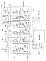
- FIG. 2 schematically shows a hydraulic circuit (hydraulic system) that operates the hydraulic actuators of the work machine 1 .
- the hydraulic system of the work machine 1 includes work system hydraulic actuators such as a boom cylinder C3, an arm cylinder C4, a bucket cylinder C5, and a swing motor MT, a first travel motor ML, and a second travel motor. It is a system that operates a travel system hydraulic actuator such as MR.
- the hydraulic system in FIG. 2 omits a circuit for controlling the dozer cylinder and the swing cylinder C2.
- a hydraulic pressure sensor 62b is provided to detect .
- the hydraulic system of the working machine 1 has a first hydraulic pump P1, a second hydraulic pump P2, and a plurality of control valves 33.
- the first hydraulic pump P1 is a pump that supplies hydraulic fluid to the work system hydraulic actuator and the travel system hydraulic actuator.
- the first hydraulic pump P1 is, for example, a constant displacement pump or a variable displacement pump.
- the second hydraulic pump P2 is a pump that supplies hydraulic oil for signaling or control, that is, pilot oil.
- the plurality of control valves 33 are valves that control the work system hydraulic actuator and the travel system hydraulic actuator.
- a first hydraulic pump P ⁇ b>1 is connected to the plurality of control valves 33 via oil passages 34 .
- the number of hydraulic pumps provided in the work machine 1 is not particularly limited, and for example, a plurality of pumps that supply hydraulic fluid to the work system hydraulic actuator and the traveling system hydraulic actuator may be provided.
- the plurality of control valves 33 includes a boom control valve 33C that controls the boom cylinder C3, an arm control valve 33D that controls the arm cylinder C4, a bucket control valve 33E that controls the bucket cylinder C5, and a swing control valve 33F that controls the swing motor MT. , a first travel control valve 33G that controls the first travel motor ML, and a second travel control valve 33H that controls the second travel motor MR.
- the boom control valve 33C is connected to the boom cylinder C3 via an oil passage 43.
- the arm control valve 33D is connected through an oil passage 44 to the arm cylinder C4.
- the bucket control valve 33E is connected through an oil passage 45 to the bucket cylinder C5.
- the swing control valve 33F is connected to the swing motor MT via an oil passage 46 .
- the first travel control valve 33G is connected to the first travel motor ML via an oil passage (first oil passage) 47 .
- the second travel control valve 33H is connected to the second travel motor MR via an oil passage (second oil passage) 48 .
- a boom electromagnetic valve 37C is connected to the pressure receiving portion of the boom control valve 33C.
- An arm electromagnetic valve 37D is connected to the pressure receiving portion of the arm control valve 33D.
- a bucket electromagnetic valve 37E is connected to the pressure receiving portion of the bucket control valve 33E.
- a swing solenoid valve 37F is connected to a pressure receiving portion of the swing control valve 33F.
- a forward travel solenoid valve 37G1 and a reverse travel solenoid valve 37G2 are connected to the pressure receiving portion of the first travel control valve 33G.
- a forward solenoid valve 37H1 and a reverse solenoid valve 37H2 are connected to the pressure receiving portion of the second travel control valve 33H.
- electromagnetic valves (37C, 37D, 37E, 37F, 37G1, 37G2, 37H1, or 37H2) are connected to the plurality of control valves 33 corresponding to the respective control valves 33.
- a second hydraulic pump P2 is connected to each solenoid valve via an oil passage (pilot oil passage) 49, and acts on the pressure receiving portion of the control valve 33 corresponding to the solenoid valve 37 according to the opening degree of the solenoid valve. pilot pressure changes.
- the configuration for controlling the operation of the control valve by electronically controlling the opening of the solenoid valve provided in the pilot oil passage will be described, but the hydraulic control method is not limited to this.
- the pilot pressure acting on the control valve may be controlled by operating a remote control valve (pilot operation valve) provided in the pilot oil passage with an operation member. may be directly electronically controlled.
- the boom control valve 33C, arm control valve 33D, bucket control valve 33E, swing control valve 33F, first travel control valve 33G, and second travel control valve 33H are, for example, direct acting spool switching valves.
- Each of the plurality of control valves 33 (33C, 33D, 33E, 33F, 33G, 33H) is supplied to the control valve 33 by pilot oil acting on the pressure receiving portion via the solenoid valve corresponding to the control valve 33. Switch the direction of the hydraulic oil, etc.
- each of the plurality of control valves 33 is operated by a work system hydraulic actuator (boom cylinder C3, arm cylinder C4, bucket cylinder C5, turning motor MT) or a travel system hydraulic actuator (first travel motor ML, second travel motor ML, second travel motor ML). It controls the flow rate of hydraulic oil supplied to the motor MR).
- a work system hydraulic actuator boom cylinder C3, arm cylinder C4, bucket cylinder C5, turning motor MT
- a travel system hydraulic actuator first travel motor ML, second travel motor ML, second travel motor ML. It controls the flow rate of hydraulic oil supplied to the motor MR).
- the work system hydraulic actuators are operated by the control device 19 (control device 19L, control device 19R).
- the operating device 19L has an operation member 40L and a first operation detection section 41L.
- the operating member 40L is a lever that can swing forward, backward, rightward, and leftward from a neutral position.
- the first operation detection section 41L detects the swing amount of the operation member 40L.
- the first operation detection unit 41L is a potentiometer that detects the swing amount (operation amount) from the front, rear, right, and left neutral positions of the operation member 40L.
- the first operation detection unit 41L detects the operation amount and the operation direction of the operation member 40L.
- the first operation detection unit 41L inputs the detected operation amount and operation direction of the operation member 40L to the control device 60 .
- the control device 60 excites the solenoid of the swing electromagnetic valve 37F connected to the pressure receiving portion of the swing control valve 33F in accordance with the amount and direction of operation of the operating member 40L. Thereby, the control device 60 controls the opening degree of the turning electromagnetic valve 37F.
- the pilot pressure acts on the pressure receiving portion of the swing control valve 33F, the position of the swing control valve 33F is switched, and the rotation direction of the swing motor MT is switched according to the position.
- control device 60 excites the solenoid of the arm electromagnetic valve 37D connected to the pressure receiving portion of the arm control valve 33D according to the operation amount and the operation direction of the operation member 40L. Thereby, the control device 60 controls the opening degree of the arm electromagnetic valve 37D. As a result, the pilot pressure acts on the pressure receiving portion of the arm control valve 33D, the position of the arm control valve 33D is switched, and the arm cylinder C4 expands and contracts according to the position.
- the control device 19R has an operation member 40R and a second operation detection section 41R.
- the operation member 40R is a lever that can swing forward, backward, rightward, and leftward from a neutral position.
- the second operation detection section 41R detects the swing amount of the operation member 40R.
- the second operation detection unit 41R is a potentiometer that detects the swing amount (operation amount) from the front, rear, right, and left neutral positions of the operation member 40R.
- the second operation detection unit 41R detects the operation amount and the operation direction of the operation member 40R.
- the second operation detection unit 41R inputs the detected operation amount and operation direction of the operation member 40R to the control device 60 .
- the control device 60 excites the solenoid of the boom electromagnetic valve 37C connected to the pressure receiving portion of the boom control valve 33C according to the operation amount and the operation direction of the operation member 40R. Thereby, the control device 60 controls the opening degree of the boom electromagnetic valve 37C.
- the pilot pressure acts on the pressure receiving portion of the boom control valve 33C, the position of the boom control valve 33C is switched, and the boom cylinder C3 expands and contracts according to the position.
- control device 60 excites the solenoid of the bucket electromagnetic valve 37E connected to the pressure receiving portion of the bucket control valve 33E according to the operation amount and the operation direction of the operation member 40R. Thereby, the control device 60 controls the opening degree of the bucket solenoid valve 37E. As a result, the pilot pressure acts on the pressure receiving portion of the bucket control valve 33E, the position of the bucket control valve 33E is switched, and the bucket cylinder C5 expands and contracts according to the position.
- the operator or the like can operate the machine body 2, the boom 15, the arm 16, and the bucket (work implement) 17 by operating the control device 19L and the control device 19R.
- the working machine 1 includes a control device 60 , a communication device 61 and an operation detection device 62 .
- the control device 60 performs hydraulic control of the electromagnetic valves and the like as described above.
- the control device 60 includes a CPU (Central Processing Unit) that executes program instructions, a ROM (read only memory) that stores computer programs, a RAM (random access memory) that develops various control programs, various control programs and various It is composed of a storage unit (recording medium) such as a memory for storing data.
- a storage unit recording medium
- the communication device 61 is a communication device (communication module) that performs either direct communication or indirect communication with an external device. ), BLE (Bluetooth (registered trademark) Low Energy), LPWA (Low Power, Wide Area), LPWAN (Low-Power Wide-Area Network), and the like. Also, the communication device 61 may be a communication device (communication module) that performs wireless communication via a mobile phone communication network, a data communication network, or the like.
- the operation detection device 62 is an angle sensor that detects the rotation angle of a member included in the working body with respect to other members, or a device that detects the stroke of the hydraulic cylinder as operation information when the work machine 1 operates.
- the operation detection device 62 is a potentiometer 62a, an oil pressure sensor 62b, and the like.
- the potentiometer 62a is, for example, a rotary shaft (first rotary shaft) between the boom 15 and the arm 16, a rotary shaft (second rotary shaft) between the boom 15 and the machine body 2, and a bucket (work implement) 17 ( third rotating shaft) and the like.
- the potentiometer 62a detects the rotation of the first rotation shaft, the second rotation shaft, and the third rotation shaft, thereby detecting the angle between the boom 15 and the arm 16 (first angle ⁇ 1), the boom 15 to the body 2 (second angle ⁇ 2), the angle of the bucket 17 to the arm 16 (third angle ⁇ 3), and the like. That is, the operation detection device 62 can detect the posture of the working object from the first angle ⁇ 1, the second angle ⁇ 2, and the third angle ⁇ 3 obtained by the potentiometer 62a.
- the method of detecting the posture (operation information) of the working object by the operation detection device 62 is not limited to the method using the potentiometer 62a.
- the operation detection device 62 may include a stroke sensor (not shown) that detects the stroke of each hydraulic cylinder (eg boom cylinder C3, arm cylinder C4, bucket cylinder C5) instead of the potentiometer 62a.
- the operation detection device 62 identifies the first angle ⁇ 1, the second angle ⁇ 2, and the third angle ⁇ 3 based on the detection results of those stroke sensors, and detects the posture of the working object.
- the hydraulic pressure sensor 62b is provided in the vicinity of the port through which hydraulic oil is introduced/discharged in each of the boom cylinder C3, the arm cylinder C4, and the bucket cylinder C5.
- the respective pressures (hydraulic cylinder pressures) of C4 and bucket cylinder C5 can be detected. That is, the operation detection device 62 detects the posture of the working object, the hydraulic cylinder pressure, etc. as operation information.
- the operation detection device 62 outputs the detected operation information to the communication device 61 .
- the communication device 61 transmits the operation information output from the operation detection device 62 to the outside.
- the work machine life prediction system includes a management device 100 . Based on operation information collected from a plurality of work machines 1 and the like, the life of a predetermined portion of the work machine is predicted.
- the management device 100 can communicate with the communication device 61 and includes a strain calculator 101 and a life calculator 102 .
- the strain calculation unit 101 and the life calculation unit 102 are composed of electric/electronic circuits provided in the management device 100, programs stored in the management device 100, and the like.
- the strain calculation unit 101 calculates the strain generated in the life prediction target portion of the working machine 1 based on the operation information detected by the operation detection device 62 . For example, the strain calculator 101 calculates the strain based on the hydraulic cylinder pressure and posture information when the hydraulic actuator operates.
- the strain calculator 101 calculates the structural data of the work machine 1, the hydraulic cylinder pressures of the hydraulic cylinders (boom cylinder C3, arm cylinder C4, bucket cylinder C5, etc.) that drive the work body, and the work body Analysis that calculates the load (reaction force) acting on the hydraulic actuators such as the boom cylinder C3, the arm cylinder C4, and the bucket cylinder C5 from the posture information (first angle ⁇ 1, second angle ⁇ 2, third angle ⁇ 3, etc.) have a model. For this reason, the strain calculation unit 101 calculates the load (reaction force) acting on the hydraulic actuator obtained from the analysis model, and the predetermined parts (life prediction target parts) of the boom 15, the arm 16, and the bucket (work tool) 17. Calculate strain.
- the strain calculation unit 101 performs structural analysis based on data on the structure prepared in advance, the hydraulic cylinder pressure of the hydraulic cylinder that drives the working body, and the attitude information of the working body. As a result, the strain calculator 101 calculates the stress, that is, the generated strain (strain) of the boom 15, the arm 16, and the bucket (work implement) 17 at predetermined portions (parts for life prediction) from the structural analysis.
- the database 104 stores hydraulic cylinder pressures of hydraulic cylinders (boom cylinder C3, arm cylinder C4, bucket cylinder C5, etc.) that drive the work object, and posture information of the work object (first angle ⁇ 1, second angle ⁇ 2, second angle ⁇ 2, 3 angles ⁇ 3, etc.) and the generated strain (strain) of the predetermined parts (parts for life prediction) of the boom 15, the arm 16, and the bucket (work tool) 17 are stored in advance (three-dimensional matrix data).
- the strain calculator 101 may calculate the strain of the life prediction target portion by referring to the data.
- the life calculation unit 102 compares the generated strain (strain) of the predetermined portion calculated by the strain calculation unit 101 with the strength of the predetermined portion obtained from the structural data of the boom 15, the arm 16 and the bucket (working tool) 17. By doing so, the life is calculated. For example, the life calculation unit 102 obtains the distribution of generated strain (strain), and compares the frequency of occurrence (number of times of occurrence) of generated strain greater than or equal to a predetermined value from the distribution with the strength of the predetermined portion, thereby determining the life of the predetermined portion. Decide if it's short or long.
- the strain calculator 101 and/or the life calculator 102 may perform the above calculations using machine learning, for example, artificial intelligence such as deep learning.
- the strain calculation unit 101 and/or the life calculation unit 102 have a learned model obtained by deep learning, and the strain (strain) generated in the learned model, the boom 15, the arm 16 and the bucket (work By applying the strength of the predetermined portion obtained from the data of the structure in 17), the life is calculated and whether the life of the predetermined portion is long or short is determined.
- the strain calculator 101 and/or the life calculator 102 may have a trained model obtained using a neural network using an algorithm other than deep learning, such as a recurrent neural network.
- the trained model generates predetermined parts (parts for life prediction) of the boom 15, the arm 16 and the bucket (work tool) 17 based on the structural data, the hydraulic cylinder pressure of the hydraulic cylinder, and the attitude information of the working object. It is a model for calculating strain (strain), or a model for calculating or obtaining life based on generated strain (strain) and structural data.
- Fig. 3 shows the operation flow of the work equipment life prediction system.
- the communication device 61 transmits operation information (workpiece posture, hydraulic cylinder pressure) detected by the operation detection device 62 , identification information for identifying the work machine 1 , to the management device 100 (S1).
- the management device 100 receives the operation information and the identification information from the communication device 61 (S1), the management device 100 stores the operation information in the database 104 for each working machine 1, that is, for each identification information (S2).
- the strain calculation unit 101 calculates the strain (generated strain) based on the operation information (hydraulic cylinder pressure and posture information) accumulated in the database 104 ( S3).
- the management device 100 causes the database 104 to store the generated strain as performance information for each working machine 1 (S4).
- the life calculation unit 102 refers to the database 104, calculates the number of times the generated strain has exceeded a predetermined value from the performance information, and Life expectancy is predicted (S5).
- the management device 100 pre-stores in the database 104 data indicating the relationship between the number of times the generated strain exceeds a predetermined value and the service life for each part of the working body, and the service life calculation unit 102 stores the data.
- the life of the target part for life prediction is predicted. It should be noted that the calculated life becomes shorter as the number of times the generated strain exceeds a predetermined value increases.
- the predetermined value may be set for each part of the working body.
- the life prediction method described above is an example and is not limited.
- the management device 100 When the life calculation unit 102 predicts the life (S5), the management device 100 notifies the life prediction result (S6). When there is a portion whose predicted life span is shorter than the predetermined period, the management device 100 notifies the predicted life span of a portion, instead of notifying the mobile terminal 105 or the like of the predetermined life span, of the portion whose life span is shorter than the predetermined period. You may make it notify that it became below.
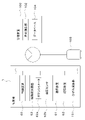
- the management device 100 includes the strain calculator 101 in the above-described embodiment, the work implement 1 may include the strain calculator 101 and the storage device 63 as shown in FIG.
- the storage device 63 stores the hydraulic cylinder pressures of the hydraulic cylinders (boom cylinder C3, arm cylinder C4, bucket cylinder C5, etc.) that drive the work body, and posture information of the work body (first angle ⁇ 1, second angle First data (three-dimensional matrix data).
- the strain calculation unit 101 calculates the frequency distribution of strain in the life prediction target part based on the hydraulic cylinder pressure and posture information detected by the operation detection device 62 and the first data stored in the storage device 63. . Then, the communication device 61 transmits the strain frequency distribution calculated by the strain calculator 101 to the management device 100 .
- the management device 100 has a life calculation unit 102 and a database 104 .
- the life calculation unit 102 calculates the life of the part to be predicted in the work machine 1 based on the strain frequency distribution received from the work machine 1 and the correspondence relationship between the strain frequency distribution and the life stored in the database 104. Calculate. Further, as shown in FIG. 5, the work machine 1 may be provided with the storage device 63, the strain calculation section 101, the life calculation section 102, and the database 104, and the work machine 1 may perform the strain calculation and the life calculation. Alternatively, as shown in FIG. 6, the work machine 1 may be provided with the storage device 63, the strain calculator 101, and the life calculator 102, and the database 104 may be provided in the management device 100. FIG. In such a case, work machine 1 performs life calculation by communicating with management device 100 and using information in database 104 .
- the life prediction system for the working machine 1 includes a working body provided on the machine body 2, a hydraulic actuator that operates the working body, and an operation detection device 62 that detects operation information when at least one of the working body and the hydraulic actuator operates. and a strain calculation unit 101 for calculating the strain of the part to be predicted for life based on the operation information detected by the operation detection device 62, and the strain calculated by the strain calculation unit 101. and a life calculation unit 102 for calculating the life of the life prediction target portion from the According to this, the strain calculation unit 101 obtains the strain from the operation information when at least one of the working body and the hydraulic actuator is operated, so that the life calculation unit 102 calculates the life of the part of the work machine 1 to be predicted. can be easily predicted. That is, the life prediction system for the work implement 1 can easily predict the life of the members provided in the work implement 1 based on the operation information of the work implement 1 .
- the operation detection device 62 detects, as operation information, the hydraulic cylinder pressure of a hydraulic cylinder provided as a hydraulic actuator and posture information of the working body, and the strain calculation unit 101 detects the hydraulic cylinder pressure and the posture information based on the hydraulic cylinder pressure and the posture information. to calculate the strain.
- the strain calculation unit 101 can easily obtain the strain from the hydraulic cylinder pressure and posture information when the hydraulic actuator is operated, and the life calculation unit 102 calculates the life from the strain obtained by the strain calculation unit 101. can be predicted.
- the operation detection device 62 detects, as posture information, a rotation angle of a member included in the working body with respect to other members, or a stroke of a hydraulic cylinder. According to this, the strain calculator 101 can easily obtain the strain from the rotation angle detected by the operation detection device 62 or the stroke of the hydraulic cylinder. Further, the life calculation unit 102 calculates the life of the part to be predicted based on the number of occurrences of strain of a predetermined value or more. According to this, the life calculation unit 102 can determine, for example, that the life of the predetermined portion is short when the number of occurrences of strain equal to or greater than the predetermined value is large, and that the life of the predetermined portion is long when the number of occurrences is small. .
- the work machine 1 includes a communication device 61 that transmits operation information, a strain calculation unit 101 and a life calculation unit 102 , and based on the operation information transmitted from the communication device 61 . and a management device 100 that predicts the life of the life prediction target part. According to this, the management device 100 can collect the operation information of the working machine 1 and easily predict the life from the collected operation information.
- the work machine 1 includes a strain calculation unit 101 and a communication device 61 that transmits information about the strain calculated by the strain calculation unit 101, includes a life calculation unit 102, and includes information about the strain transmitted from the communication device 61.
- a management device 100 for predicting the life of a part included in the working machine 1 for life prediction based on the above. According to this, the work machine 1 can easily obtain the strain, and by transmitting the obtained strain to the management device 100, the management device 100 can easily obtain the life. That is, the working machine 1 and the management device 100 cooperate with each other to easily determine the life.
- work machine 1 includes strain calculation section 101 and life calculation section 102 . According to this, the working machine 1 can easily obtain the life without communicating with the management device 100 . It should be considered that the embodiments disclosed this time are illustrative in all respects and not restrictive. The scope of the present invention is indicated by the scope of the claims rather than the above description, and is intended to include all changes within the meaning and scope equivalent to the scope of the claims.
- Reference Signs List 1 Working machine 2 : Machine body 3 : Traveling device 4 : Working device 15 : Boom 16 : Arm 17 : Bucket 60 : Control device 61 : Communication device 62 : Operation detection device 62a : Potentiometer 62b : Hydraulic sensor 65 : Storage device 100 : Management device 101 : Strain calculation unit 102 : Life calculation unit 104 : Database 105 : Portable terminal C2 : Swing cylinder C3 : Boom cylinder C4 : Arm cylinder C5 : Bucket cylinder
Landscapes
- Engineering & Computer Science (AREA)
- Mining & Mineral Resources (AREA)
- Civil Engineering (AREA)
- General Engineering & Computer Science (AREA)
- Structural Engineering (AREA)
- Physics & Mathematics (AREA)
- General Physics & Mathematics (AREA)
- Operation Control Of Excavators (AREA)
- Testing Of Devices, Machine Parts, Or Other Structures Thereof (AREA)
Abstract
作業機(1)の寿命予測システムは、機体(2)に設けられた作業体と、前記作業体を作動させる油圧アクチュエータと、前記作業体及び油圧アクチュエータの少なくとも一方が作動したときの稼働情報を検出する稼働検出装置(62)とを備えた作業機(1)の寿命予測システムであって、前記稼働検出装置(62)が検出した稼働情報に基づいて寿命予測対象部位のひずみを演算するひずみ演算部(101)と、前記ひずみ演算部(101)で演算したひずみから前記寿命予測対象部位の寿命を演算する寿命演算部(102)と、を備えている。
Description
本発明は、作業機の寿命予測システムに関する。
従来、特許文献1に開示された作業機の故障を診断するシステムが知られている。
特許文献1の作業機の動作状況取込システムは、作業機の各部位における動作状況を電子メールにてサーバに送信する送信手段と、サーバにアクセス可能なコンピュータとを備え、コンピュータは、サーバにアクセスして当該サーバに保存された動作状況を取り込む状況取込部と、状況取込部で取り込まれた動作状況を表示する表示部と、取り込まれた動作状況に基づいて作業機の故障を自動的に推定する故障推定部とを備えている。
特許文献1の作業機の動作状況取込システムは、作業機の各部位における動作状況を電子メールにてサーバに送信する送信手段と、サーバにアクセス可能なコンピュータとを備え、コンピュータは、サーバにアクセスして当該サーバに保存された動作状況を取り込む状況取込部と、状況取込部で取り込まれた動作状況を表示する表示部と、取り込まれた動作状況に基づいて作業機の故障を自動的に推定する故障推定部とを備えている。
さて、特許文献1に開示されている作業機の動作状況取込システムでは、エラー、警告などが発生した場合の動作状況から故障を診断することができるものの、作業機に備えられる部材の寿命までは予測できないのが実情である。
そこで本発明は、上記課題に鑑み、作業機の稼働情報に基づいて当該作業機に備えられる部材の寿命を簡単に予測することができる作業機の寿命予測システムを提供することを目的とする。
そこで本発明は、上記課題に鑑み、作業機の稼働情報に基づいて当該作業機に備えられる部材の寿命を簡単に予測することができる作業機の寿命予測システムを提供することを目的とする。
本発明の一態様に係る作業機の寿命予測システムは、機体に設けられた作業体と、前記作業体を作動させる油圧アクチュエータと、前記作業体及び油圧アクチュエータの少なくとも一方が作動したときの稼働情報を検出する稼働検出装置とを備えた作業機の寿命予測システムであって、前記管理装置は、前記稼働検出装置が検出した稼働情報に基づいて寿命予測対象部位のひずみを演算するひずみ演算部と、前記ひずみ演算部で演算したひずみから前記寿命予測対象部位の寿命を演算する寿命演算部と、を備えている。
また、前記稼働検出装置は、前記稼働情報として、前記油圧アクチュエータとして備えられる油圧シリンダの油圧シリンダ圧と、前記作業体の姿勢情報とを検出し、前記ひずみ演算部は、前記油圧シリンダ圧と前記姿勢情報とに基づいて、前記ひずみを演算する。
また、前記稼働検出装置は、前記姿勢情報として、前記作業体に含まれる部材の他の部材に対する回転角度、または前記油圧シリンダのストロークを検出する。
また、前記稼働検出装置は、前記姿勢情報として、前記作業体に含まれる部材の他の部材に対する回転角度、または前記油圧シリンダのストロークを検出する。
また、前記寿命演算部は、所定値以上のひずみが発生した発生回数に基づいて前記寿命予測対象部位の寿命を演算する。
また、作業機の寿命予測システムは、前記作業機に設けられ且つ、前記稼働情報を送信する通信装置と、前記ひずみ演算部及び前記寿命演算部を含み、前記通信装置から送信された稼働情報に基づいて当該作業機に含まれる前記寿命予測対象部位の寿命を予測する管理装置と、を備えている。
また、作業機の寿命予測システムは、前記作業機に設けられ且つ、前記稼働情報を送信する通信装置と、前記ひずみ演算部及び前記寿命演算部を含み、前記通信装置から送信された稼働情報に基づいて当該作業機に含まれる前記寿命予測対象部位の寿命を予測する管理装置と、を備えている。
また、前記作業機は、前記ひずみ演算部と、前記ひずみ演算部が演算したひずみに関する情報を送信する通信装置とを備え、前記寿命演算部を含み、前記通信装置から送信された前記ひずみに関する情報に基づいて当該作業機に含まれる前記寿命予測対象部位の寿命を予測する管理装置を備えている。
また、前記作業機が前記ひずみ演算部と前記寿命演算部とを備えている。
また、前記作業機が前記ひずみ演算部と前記寿命演算部とを備えている。
本発明によれば、作業体及び油圧アクチュエータの少なくとも一方が作動したときの稼働情報から寿命予測対象部位の寿命を簡単に予測することができる。
以下、本発明の一実施形態について、図面を適宜参照しつつ説明する。
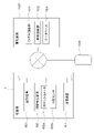
図1は、作業機の寿命予測システムの全体図を示している。作業機の寿命予測システムは、複数の作業機1から稼働情報を収集して各作業機1における寿命予測対象部位の寿命予測を行うシステムである。
まず、作業機1について説明する。図7は、作業機1として旋回作業機であるバックホーを示している。作業機1は、バックホーに限定されず、ローダ等の建設機械、トラクタ、コンバイン、田植機等の農業機械であってもよい。
図1は、作業機の寿命予測システムの全体図を示している。作業機の寿命予測システムは、複数の作業機1から稼働情報を収集して各作業機1における寿命予測対象部位の寿命予測を行うシステムである。
まず、作業機1について説明する。図7は、作業機1として旋回作業機であるバックホーを示している。作業機1は、バックホーに限定されず、ローダ等の建設機械、トラクタ、コンバイン、田植機等の農業機械であってもよい。
図7に示すように、作業機1は、機体(旋回台)2と、走行装置3と、作業装置4とを備えている。機体2上にはキャビン5が搭載されている。キャビン5の室内には運転席6が設けられている。
本実施形態においては、作業機1の運転席6に着座した運転者(オペレータ)が向く方向(図7の矢印A1方向)を前方といい、その反対方向(図7の矢印A2方向)を後方という。また、運転者の左側(図7の手前側)を左方といい、運転者の右側(図7の奥側)を右方という。
本実施形態においては、作業機1の運転席6に着座した運転者(オペレータ)が向く方向(図7の矢印A1方向)を前方といい、その反対方向(図7の矢印A2方向)を後方という。また、運転者の左側(図7の手前側)を左方といい、運転者の右側(図7の奥側)を右方という。
また、前後方向K1に直交する方向である水平方向を機体幅方向という。機体2の幅方向の中央部から右部、或いは、左部へ向かう方向を機体外方という。言い換えれば、機体外方とは、機体幅方向であって機体2の幅方向の中心から離れる方向のことである。機体外方とは反対の方向を、機体内方という。言い換えれば、機体内方とは、機体幅方向であって機体2の幅方向の中心に近づく方向である。
図7に示すように、走行装置3は、左側に設けられた走行体3Lと、右側に設けられた走行体3Rとを有する。走行体3L及び走行体3Rは、駆動輪11aと、従動輪11bと、複数の転輪11eと、フレーム11cと、ベルト11dとを有するクローラ式の走行装置である。フレーム11cは、駆動輪11a、従動輪11b、及び転輪11eを回転自在に支持する。ベルト11dは、駆動輪11a、従動輪11b、及び転輪11eに架け渡されている。
走行体3Lのフレーム11cは、第1走行モータMLを支持している。第1走行モータMLの動力は、走行体3Lの駆動輪11aに伝達される。また、走行体3Rのフレーム11cは、第2走行モータMRを支持している。第2走行モータMRの動力は、走行体3Rの駆動輪11aに伝達される。
走行装置3の前部には、ドーザ装置7が装着されている。ドーザ装置7は、ドーザシリンダを伸縮することにより昇降(ブレードを上げ下げ)させることができる。なお、作業機1は、ドーザ装置7を備えない構成であってもよい。
走行装置3の前部には、ドーザ装置7が装着されている。ドーザ装置7は、ドーザシリンダを伸縮することにより昇降(ブレードを上げ下げ)させることができる。なお、作業機1は、ドーザ装置7を備えない構成であってもよい。
機体2は、走行装置3上に旋回ベアリング8を介して縦軸(上下の方向に延伸する軸心)回りに旋回自在に支持されている。機体2は、油圧モータ(油圧アクチュエータ)からなる旋回モータMTによって旋回駆動される。機体2は、縦軸回りに旋回する旋回基板9と、ウエイト10とを有している。旋回基板9は、鋼板等から形成されており、旋回ベアリング8に連結されている。ウエイト10は、機体2の後部に設けられている。機体2の後部には、原動機E1が搭載されている。原動機E1は、ディーゼルエンジンである。なお、原動機E1は、電動モータであってもよいし、ディーゼルエンジン及び電動モータを有するハイブリッド型であってもよい。
機体2は、機体幅方向の中央のやや右寄りの前部に支持ブラケット13を有している。支持ブラケット13には、スイングブラケット14が、縦軸回りに揺動自在に取り付けられている。スイングブラケット14には、作業装置4が取り付けられている。
図7に示すように、作業装置4は、ブーム15、アーム16、バケット(作業具)17等の作業体を有している。ブーム15の基部は、スイングブラケット14に横軸(機体幅方向に延伸する軸心)回りに回動自在に枢着されている。このため、ブーム15は、上下に揺動自在である。アーム16は、ブーム15の先端側に横軸回りに回動自在に枢着されている。このため、アーム16は、前後或いは上下に揺動自在である。バケット17は、アーム16の先端側にスクイ動作及びダンプ動作可能に設けられている。作業機1は、バケット17に代えて或いは加えて、油圧アクチュエータにより駆動可能な他の作業具(予備アタッチメント)を装着することが可能である。他の作業具(予備アタッチメント)としては、油圧ブレーカ、油圧圧砕機、アングルブルーム、アースオーガ、パレットフォーク、スイーパー、モア、スノウブロア等が例示できる。
図7に示すように、作業装置4は、ブーム15、アーム16、バケット(作業具)17等の作業体を有している。ブーム15の基部は、スイングブラケット14に横軸(機体幅方向に延伸する軸心)回りに回動自在に枢着されている。このため、ブーム15は、上下に揺動自在である。アーム16は、ブーム15の先端側に横軸回りに回動自在に枢着されている。このため、アーム16は、前後或いは上下に揺動自在である。バケット17は、アーム16の先端側にスクイ動作及びダンプ動作可能に設けられている。作業機1は、バケット17に代えて或いは加えて、油圧アクチュエータにより駆動可能な他の作業具(予備アタッチメント)を装着することが可能である。他の作業具(予備アタッチメント)としては、油圧ブレーカ、油圧圧砕機、アングルブルーム、アースオーガ、パレットフォーク、スイーパー、モア、スノウブロア等が例示できる。
スイングブラケット14は、機体2内に備えられたスイングシリンダC2の伸縮によって揺動自在である。ブーム15は、ブームシリンダC3の伸縮によって揺動自在である。アーム16は、アームシリンダC4の伸縮によって揺動自在である。バケット17は、バケットシリンダ(作業具シリンダ)C5の伸縮によってスクイ動作及びダンプ動作自在である。ドーザシリンダ、スイングシリンダC2、ブームシリンダC3、アームシリンダC4、及びバケットシリンダC5は、油圧シリンダ(油圧アクチュエータ)によって構成されている。
なお、作業装置4は、機体2に設けられたものであればよく、ブーム15、アーム16及びバケット(作業具)17以外を有していてもよい。また、ブームシリンダC3、アームシリンダC4、バケットシリンダC5等は、作業体を駆動する油圧アクチュエータである。
図2は、作業機1の油圧アクチュエータを作動させる油圧回路(油圧システム)の概略を示している。
図2は、作業機1の油圧アクチュエータを作動させる油圧回路(油圧システム)の概略を示している。
図2に示すように、作業機1の油圧システムは、ブームシリンダC3、アームシリンダC4、バケットシリンダC5、及び旋回モータMT等の作業系油圧アクチュエータと、第1走行モータML、及び第2走行モータMR等の走行系油圧アクチュエータとを作動させるシステムである。なお、図2の油圧システムは、説明の便宜上、ドーザシリンダ及びスイングシリンダC2を制御する回路を省略している。また、ブームシリンダC3、アームシリンダC4、及びバケットシリンダC5における作動油が導入/排出されるポートの近傍には、ブームシリンダC3、アームシリンダC4、及びバケットシリンダC5のそれぞれの圧力(油圧シリンダ圧)を検出する油圧センサ62bが備えられている。
作業機1の油圧システムは、第1油圧ポンプP1と、第2油圧ポンプP2と、複数の制御弁33を有している。第1油圧ポンプP1は、作業系油圧アクチュエータ及び走行系油圧アクチュエータに作動油を供給するポンプである。第1油圧ポンプP1は、例えば、定容量ポンプ、或いは、可変容量ポンプである。また、第2油圧ポンプP2は、信号用又は制御用等の作動油、即ち、パイロット油を供給するポンプである。複数の制御弁33は、作業系油圧アクチュエータ、走行系油圧アクチュエータを制御する弁である。複数の制御弁33には、油路34を介して第1油圧ポンプP1が接続されている。なお、作業機1に備えられる油圧ポンプの数は特に限定されず、例えば、作業系油圧アクチュエータ及び走行系油圧アクチュエータに作動油を供給するポンプを複数備えていてもよい。
複数の制御弁33は、ブームシリンダC3を制御するブーム制御弁33C、アームシリンダC4を制御するアーム制御弁33D、バケットシリンダC5を制御するバケット制御弁33E、旋回モータMTを制御する旋回制御弁33F、第1走行モータMLを制御する第1走行制御弁33G、第2走行モータMRを制御する第2走行制御弁33Hを含んでいる。
ブーム制御弁33Cは、油路43を介してブームシリンダC3に接続されている。アーム制御弁33Dは、油路44を介してアームシリンダC4に接続されている。バケット制御弁33Eは、油路45を介してバケットシリンダC5に接続されている。旋回制御弁33Fは、油路46を介して旋回モータMTに接続されている。第1走行制御弁33Gは、油路(第1油路)47を介して第1走行モータMLに接続されている。第2走行制御弁33Hは、油路(第2油路)48を介して第2走行モータMRに接続されている。
ブーム制御弁33Cの受圧部には、ブーム電磁弁37Cが接続されている。アーム制御弁33Dの受圧部には、アーム電磁弁37Dが接続されている。バケット制御弁33Eの受圧部には、バケット電磁弁37Eが接続されている。旋回制御弁33Fの受圧部には、旋回電磁弁37Fが接続されている。第1走行制御弁33Gの受圧部には、前進電磁弁37G1及び後進電磁弁37G2が接続されている。第2走行制御弁33Hの受圧部には、前進電磁弁37H1及び後進電磁弁37H2が接続されている。
即ち、複数の制御弁33には、それぞれの制御弁33に対応して、電磁弁(37C、37D、37E、37F、37G1、37G2、37H1、又は37H2)が接続されている。各電磁弁には、油路(パイロット油路)49を介して第2油圧ポンプP2が接続され、当該電磁弁の開度に応じて当該電磁弁37に対応する制御弁33の受圧部に作用するパイロット圧が変化する。
なお、本実施形態では、パイロット油路に備えられている電磁弁の開度を電子制御することにより制御弁の動作を制御する構成について説明するが、油圧制御方式はこれに限るものではない。例えば、パイロット油路に備えられたリモコン弁(パイロット操作弁)を操作部材で操作することにより制御弁に作用するパイロット圧を制御する構成としてもよく、制御弁を電磁弁で構成して制御弁の動作を直接電子制御する構成にしてもよい。
ブーム制御弁33C、アーム制御弁33D、バケット制御弁33E、旋回制御弁33F、第1走行制御弁33G、第2走行制御弁33Hは、例えば、直動スプール形の切換弁である。複数の制御弁33(33C、33D、33E、33F、33G、33H)のそれぞれは、当該制御弁33に対応する電磁弁を介して受圧部に作用するパイロット油によって、当該制御弁33に供給された作動油の方向等を切り換える。これにより、複数の制御弁33のそれぞれは、作業系油圧アクチュエータ(ブームシリンダC3、アームシリンダC4、バケットシリンダC5、旋回モータMT)、或いは、走行系油圧アクチュエータ(第1走行モータML、第2走行モータMR)に供給される作動油の流量等を制御する。
作業系油圧アクチュエータは、操縦装置19(操縦装置19L、操縦装置19R)によって操作される。操縦装置19Lは、操作部材40Lと、第1操作検出部41Lとを有している。操作部材40Lは、中立位置から、前、後、右、左に揺動自在なレバーである。第1操作検出部41Lは、操作部材40Lの揺動量を検出する。また、第1操作検出部41Lは、操作部材40Lの前、後、右、左の中立位置からの揺動量(操作量)を検出するポテンションメータである。
操作部材40Lをオペレータ等が操作すると、第1操作検出部41Lは、操作部材40Lの操作量及び操作方向を検出する。第1操作検出部41Lは、当該検出した操作部材40Lの操作量及び操作方向を制御装置60に入力する。制御装置60は、操作部材40Lの操作量及び操作方向に応じて、旋回制御弁33Fの受圧部に接続された旋回電磁弁37Fのソレノイドを励磁する。これにより、制御装置60は、当該旋回電磁弁37Fの開度を制御する。その結果、旋回制御弁33Fの受圧部にパイロット圧が作用し、当該旋回制御弁33Fは、位置が切り換えられ、当該位置に応じて旋回モータMTの回転方向が切り換える。
また、制御装置60は、操作部材40Lの操作量及び操作方向に応じて、アーム制御弁33Dの受圧部に接続されたアーム電磁弁37Dのソレノイドを励磁する。これにより、制御装置60は、当該アーム電磁弁37Dの開度を制御する。その結果、アーム制御弁33Dの受圧部にパイロット圧が作用し、当該アーム制御弁33Dは、位置が切り換えられ、位置に応じてアームシリンダC4が伸縮する。
操縦装置19Rは、操作部材40Rと、第2操作検出部41Rとを有している。操作部材40Rは、中立位置から、前、後、右、左に揺動自在なレバーである。第2操作検出部41Rは、操作部材40Rの揺動量を検出する。また、第2操作検出部41Rは、操作部材40Rの前、後、右、左の中立位置からの揺動量(操作量)を検出するポテンションメータである。
操作部材40Rをオペレータ等が操作すると、第2操作検出部41Rは、操作部材40Rの操作量及び操作方向を検出する。第2操作検出部41Rは、当該検出した操作部材40Rの操作量及び操作方向を制御装置60に入力する。制御装置60は、操作部材40Rの操作量及び操作方向に応じて、ブーム制御弁33Cの受圧部に接続されたブーム電磁弁37Cのソレノイドを励磁する。これにより、制御装置60は、当該ブーム電磁弁37Cの開度を制御する。その結果、ブーム制御弁33Cの受圧部にパイロット圧が作用し、当該ブーム制御弁33Cは、位置が切り換えられ、当該位置に応じてブームシリンダC3が伸縮する。
また、制御装置60は、操作部材40Rの操作量及び操作方向に応じて、バケット制御弁33Eの受圧部に接続されたバケット電磁弁37Eのソレノイドを励磁する。これにより、制御装置60は、当該バケット電磁弁37Eの開度を制御する。その結果、バケット制御弁33Eの受圧部にパイロット圧が作用し、当該バケット制御弁33Eは、位置が切り換えられ、当該位置に応じてバケットシリンダC5が伸縮する。
以上のように、オペレータ等は、操縦装置19L及び操縦装置19Rを操作することによって、機体2、ブーム15、アーム16、バケット(作業具)17を操作することができる。
図1に示すように、作業機1は、制御装置60と、通信装置61と、稼働検出装置62と、を備えている。制御装置60は、上述したように電磁弁等の油圧制御を行う。制御装置60は、プログラムの命令を実行するCPU(Central Processing Unit)、コンピュータプログラムを格納したROM(read only memory)、各種の制御プログラムを展開するRAM(random access memory)、各種の制御プログラムおよび各種データを格納するメモリ等の記憶部(記録媒体)などにより構成されている。
図1に示すように、作業機1は、制御装置60と、通信装置61と、稼働検出装置62と、を備えている。制御装置60は、上述したように電磁弁等の油圧制御を行う。制御装置60は、プログラムの命令を実行するCPU(Central Processing Unit)、コンピュータプログラムを格納したROM(read only memory)、各種の制御プログラムを展開するRAM(random access memory)、各種の制御プログラムおよび各種データを格納するメモリ等の記憶部(記録媒体)などにより構成されている。
通信装置61は、外部機器に対して直接通信及び間接通信のいずれかを行う通信装置(通信モジュール)であって、例えば、通信規格であるIEEE802.11シリーズのWi-Fi(Wireless Fidelity、登録商標)、BLE(Bluetooth(登録商標) Low Energy)、LPWA(Low Power, Wide Area)、LPWAN(Low-Power Wide-Area Network)等により無線通信を行うことができる。また、通信装置61は、携帯電話通信網又はデータ通信網などにより無線通信を行う通信装置(通信モジュール)であってもよい。
稼働検出装置62は、作業機1が作動したときの稼働情報として、作業体に含まれる部材の他の部材に対する回転角度を検出する角度センサ、または油圧シリンダのストロークを検出する装置である。具体的には、稼働検出装置62は、ポテンショメータ62a、及び油圧センサ62b等である。ポテンショメータ62aは、例えば、ブーム15とアーム16との回動軸(第1回動軸)、ブーム15と機体2との回動軸(第2回動軸)、バケット(作業具)17の(第3回動軸)等に設けられている。このため、ポテンショメータ62aは、第1回動軸、第2回動軸、第3回動軸の回動を検出することによって、ブーム15とアーム16との角度(第1角度θ1)、ブーム15の機体2に対する角度(第2角度θ2)、バケット17のアーム16に対する角度(第3角度θ3)等を検出する。即ち、稼働検出装置62は、ポテンショメータ62aによって得られた第1角度θ1、第2角度θ2、第3角度θ3によって作業体の姿勢を検出することができる。
なお、稼働検出装置62が作業体の姿勢(稼働情報)の検出方法は、ポテンショメータ62aを用いる方法に限るものではない。例えば、稼働検出装置62は、ポテンショメータ62aに代えて、各油圧シリンダ(例えばブームシリンダC3、アームシリンダC4、バケットシリンダC5)のストロークを検出するストロークセンサ(図示せず)を備えていてもよい。斯かる場合、稼働検出装置62は、それらのストロークセンサの検出結果に基づいて上記の第1角度θ1、第2角度θ2、及び第3角度θ3を特定し、作業体の姿勢を検出する。
図2に示すように、油圧センサ62bは、ブームシリンダC3、アームシリンダC4、バケットシリンダC5のそれぞれにおいて、作動油が導入/排出されるポートの近傍に設けられていて、ブームシリンダC3、アームシリンダC4、バケットシリンダC5のそれぞれの圧力(油圧シリンダ圧)を検出することができる。
つまり、稼働検出装置62は、作業体の姿勢、油圧シリンダ圧などを稼働情報として検出する。稼働検出装置62は、当該検出した稼働情報を通信装置61に出力する。通信装置61は、稼働検出装置62から出力された稼働情報を外部に送信する。
つまり、稼働検出装置62は、作業体の姿勢、油圧シリンダ圧などを稼働情報として検出する。稼働検出装置62は、当該検出した稼働情報を通信装置61に出力する。通信装置61は、稼働検出装置62から出力された稼働情報を外部に送信する。
図1に示すように、作業機の寿命予測システムは、管理装置100を備えている。複数の作業機1等から収集した稼働情報に基づいて作業機の所定部位の寿命を予測する。
管理装置100は、通信装置61と通信可能であって、ひずみ演算部101と、寿命演算部102とを備えている。ひずみ演算部101及び寿命演算部102は、管理装置100に設けられた電気電子回路、当該管理装置100に格納されたプログラム等から構成されている。
ひずみ演算部101は、稼働検出装置62が検出した稼働情報に基づいて、作業機1の寿命予測対象部位に生じたひずみを演算する。例えば、ひずみ演算部101は、油圧アクチュエータが作動したときの油圧シリンダ圧と姿勢情報とに基づいて、ひずみを演算する。
管理装置100は、通信装置61と通信可能であって、ひずみ演算部101と、寿命演算部102とを備えている。ひずみ演算部101及び寿命演算部102は、管理装置100に設けられた電気電子回路、当該管理装置100に格納されたプログラム等から構成されている。
ひずみ演算部101は、稼働検出装置62が検出した稼働情報に基づいて、作業機1の寿命予測対象部位に生じたひずみを演算する。例えば、ひずみ演算部101は、油圧アクチュエータが作動したときの油圧シリンダ圧と姿勢情報とに基づいて、ひずみを演算する。
具体的には、ひずみ演算部101は、作業機1の構造体のデータと、作業体を駆動する油圧シリンダ(ブームシリンダC3、アームシリンダC4、バケットシリンダC5等)の油圧シリンダ圧と、作業体の姿勢情報(第1角度θ1、第2角度θ2、第3角度θ3等)とから、ブームシリンダC3、アームシリンダC4、バケットシリンダC5等の油圧アクチュエータに作用する負荷(反力)を演算する解析モデルを有している。このため、ひずみ演算部101は、当該解析モデルから得られた油圧アクチュエータに作用する負荷(反力)から、ブーム15、アーム16及びバケット(作業具)17の所定部位(寿命予測対象部位)のひずみを演算する。
即ち、ひずみ演算部101は、予め用意された構造体のデータ、作業体を駆動する油圧シリンダの油圧シリンダ圧、及び作業体の姿勢情報に基づいて構造解析を行う。これにより、ひずみ演算部101は、当該構造解析からブーム15、アーム16及びバケット(作業具)17の所定部位(寿命予測対象部位)の応力、即ち、発生ひずみ(ひずみ)を演算する。
なお、データベース104が、作業体を駆動する油圧シリンダ(ブームシリンダC3、アームシリンダC4、バケットシリンダC5等)の油圧シリンダ圧と、作業体の姿勢情報(第1角度θ1、第2角度θ2、第3角度θ3等)と、ブーム15、アーム16及びバケット(作業具)17の所定部位(寿命予測対象部位)の発生ひずみ(ひずみ)とを対応付けたデータ(3次元マトリクスデータ)を予め記憶し、ひずみ演算部101は、当該データを参照することで寿命予測対象部位のひずみを算出するようにしてもよい。
寿命演算部102は、ひずみ演算部101で演算した所定部位の発生ひずみ(ひずみ)と、ブーム15、アーム16及びバケット(作業具)17の構造体のデータから得られる所定部位の強度とを比較することで、寿命を演算する。例えば、寿命演算部102は、発生ひずみ(ひずみ)の分布を求め、分布から所定以上の発生ひずみの発生頻度(発生回数)と、所定部位の強度とを比較することで、所定部位の寿命が短いか長いかを判断する。
なお、ひずみ演算部101及び/又は寿命演算部102が、上述した演算を、機械学習、例えば、ディープラーニング(深層学習)などの人工知能を用いて行うようにしてもよい。具体的には、ひずみ演算部101及び/又は寿命演算部102は、深層学習により得られた学習済みモデルを有し、学習済みモデルに発生ひずみ(ひずみ)、ブーム15、アーム16及びバケット(作業具)17の構造体のデータから得られる所定部位の強度等を適用することで、寿命を演算したり、所定部位の寿命が長いか短いかを判断したりする。あるいは、ひずみ演算部101及び/又は寿命演算部102が、深層学習以外のアルゴリズムを用いたニューラルネットワーク、例えばリカレントニューラルネットワークを用いて得られた学習済みモデルを有していてもよい。なお、学習済みモデルは、構造体のデータ、油圧シリンダの油圧シリンダ圧及び作業体の姿勢情報に基づいてブーム15、アーム16及びバケット(作業具)17の所定部位(寿命予測対象部位)の発生ひずみ(ひずみ)を演算するモデル、又は、発生ひずみ(ひずみ)、構造体のデータに基づいて寿命を演算したり、寿命を求めたりするモデルである。
図3は、作業機の寿命予測システムの動作フローを示している。図3に示すように、作業機1が作動すると、通信装置61は、稼働検出装置62が検出した稼働情報(作業体の姿勢、油圧シリンダ圧)と、作業機1を識別する識別情報と、を管理装置100に送信する(S1)。管理装置100は、通信装置61から稼働情報及び識別情報を受信すると(S1)、作業機1毎、即ち、識別情報毎に稼働情報をデータベース104に記憶させる(S2)。
データベース104が識別情報毎に稼働情報を記憶すると(S2)、ひずみ演算部101は、データベース104に蓄積された稼働情報(油圧シリンダ圧及び姿勢情報)に基づいてひずみ(発生ひずみ)を演算する(S3)。ひずみ演算部101が発生ひずみを演算すると(S3)、管理装置100は、作業機1毎に実績情報として発生ひずみをデータベース104に記憶させる(S4)。
データベース104が作業機1毎に発生ひずみを記憶すると(S4)、寿命演算部102は、データベース104を参照し、実績情報から発生ひずみが所定値以上になった発生回数を演算し、発生回数から寿命を予測する(S5)。例えば、管理装置100は、発生ひずみが所定以上になった回数と寿命との関係を作業体の部位毎に示したデータを予めデータベース104に記憶させておき、寿命演算部102は、当該データを参照することで寿命予測対象部位の寿命を予測する。なお、発生ひずみが所定値以上になった回数が多くなるほど、演算される寿命は短くなる。また、上記所定値は作業体の部位毎に設定してもよい。また、上述した寿命の予測方法は一例であり限定されない。
寿命演算部102が寿命を予測すると(S5)、管理装置100は、寿命予測結果を通知する(S6)。なお、管理装置100は、予測寿命が所定期間以下の部位が生じた場合、寿命予測結果を通知する代わりに、予め定められた携帯端末105等に寿命が短くなった部位と、寿命が所定期間以下になったことを通知するようにしてもよい。
なお、上述した実施形態において、管理装置100がひずみ演算部101を備えているが、図4に示すように、作業機1は、ひずみ演算部101と、記憶装置63を備えていてもよい。斯かる場合において、記憶装置63は、作業体を駆動する油圧シリンダ(ブームシリンダC3、アームシリンダC4、バケットシリンダC5等)の油圧シリンダ圧と、作業体の姿勢情報(第1角度θ1、第2角度θ2、第3角度θ3等)と、ブーム15、アーム16、及びバケット(作業具)17の所定部位(寿命予測対象部位)の発生ひずみ(ひずみ)とを対応付けた第1データ(3次元マトリクスデータ)を記憶している。ひずみ演算部101は、稼働検出装置62が検出した油圧シリンダ圧及び姿勢情報と、記憶装置63に記憶している第1データと、に基づいて、寿命予測対象部位におけるひずみの頻度分布を演算する。そして、通信装置61は、ひずみ演算部101が演算したひずみの頻度分布を管理装置100に送信する。
なお、上述した実施形態において、管理装置100がひずみ演算部101を備えているが、図4に示すように、作業機1は、ひずみ演算部101と、記憶装置63を備えていてもよい。斯かる場合において、記憶装置63は、作業体を駆動する油圧シリンダ(ブームシリンダC3、アームシリンダC4、バケットシリンダC5等)の油圧シリンダ圧と、作業体の姿勢情報(第1角度θ1、第2角度θ2、第3角度θ3等)と、ブーム15、アーム16、及びバケット(作業具)17の所定部位(寿命予測対象部位)の発生ひずみ(ひずみ)とを対応付けた第1データ(3次元マトリクスデータ)を記憶している。ひずみ演算部101は、稼働検出装置62が検出した油圧シリンダ圧及び姿勢情報と、記憶装置63に記憶している第1データと、に基づいて、寿命予測対象部位におけるひずみの頻度分布を演算する。そして、通信装置61は、ひずみ演算部101が演算したひずみの頻度分布を管理装置100に送信する。
管理装置100は、寿命演算部102とデータベース104とを備えている。寿命演算部102は、作業機1から受信したひずみの頻度分布と、データベース104に記憶しているひずみの頻度分布と寿命との対応関係とに基づいて作業機1における寿命予測対象部位の寿命を演算する。
また、図5に示すように、記憶装置63、ひずみ演算部101、及び寿命演算部102、データベース104を作業機1に備え、作業機1でひずみ演算及び寿命演算を行うようにしてもよい。また、図6に示すように、記憶装置63、ひずみ演算部101、及び寿命演算部102を作業機1に備え、データベース104を管理装置100に備えるような構成であってもよい。斯かる場合、作業機1が管理装置100と通信を行ってデータベース104の情報を利用することで寿命演算を行う。
また、図5に示すように、記憶装置63、ひずみ演算部101、及び寿命演算部102、データベース104を作業機1に備え、作業機1でひずみ演算及び寿命演算を行うようにしてもよい。また、図6に示すように、記憶装置63、ひずみ演算部101、及び寿命演算部102を作業機1に備え、データベース104を管理装置100に備えるような構成であってもよい。斯かる場合、作業機1が管理装置100と通信を行ってデータベース104の情報を利用することで寿命演算を行う。
作業機1の寿命予測システムは、機体2に設けられた作業体と、作業体を作動させる油圧アクチュエータと、作業体及び油圧アクチュエータの少なくとも一方が作動したときの稼働情報を検出する稼働検出装置62とを備えた作業機1の寿命予測システムであって、稼働検出装置62が検出した稼働情報に基づいて寿命予測対象部位のひずみを演算するひずみ演算部101と、ひずみ演算部101で演算したひずみから寿命予測対象部位の寿命を演算する寿命演算部102と、を備えている。これによれば、ひずみ演算部101が、作業体及び油圧アクチュエータの少なくとも一方を作動させたときの稼働情報からひずみを求めることで、寿命演算部102は、作業機1の寿命予測対象部位の寿命を簡単に予測することができる。即ち、作業機1の寿命予測システムは、作業機1の稼働情報に基づいて当該作業機1に備えられる部材の寿命を簡単に予測することができる。
また、稼働検出装置62は、稼働情報として、油圧アクチュエータとして備えられる油圧シリンダの油圧シリンダ圧と、作業体の姿勢情報とを検出し、ひずみ演算部101は、油圧シリンダ圧と姿勢情報とに基づいて、ひずみを演算する。これによれば、油圧アクチュエータが作動したときの油圧シリンダ圧及び姿勢情報によって、ひずみ演算部101が簡単にひずみを求めることができ、寿命演算部102は、ひずみ演算部101が求めたひずみから寿命を予測することができる。
また、稼働検出装置62は、姿勢情報として、作業体に含まれる部材の他の部材に対する回転角度、または油圧シリンダのストロークを検出する。これによれば、ひずみ演算部101は、稼働検出装置62が検出した回転角度、または油圧シリンダのストロークによって、簡単にひずみを求めることができる。
また、寿命演算部102は、所定値以上のひずみが発生した発生回数に基づいて寿命予測対象部位の寿命を演算する。これによれば、寿命演算部102は、例えば、所定値以上のひずみの発生回数が多い場合は所定部位の寿命が短く、発生回数が少ない場合は所定部位の寿命は長いと判断することができる。
また、寿命演算部102は、所定値以上のひずみが発生した発生回数に基づいて寿命予測対象部位の寿命を演算する。これによれば、寿命演算部102は、例えば、所定値以上のひずみの発生回数が多い場合は所定部位の寿命が短く、発生回数が少ない場合は所定部位の寿命は長いと判断することができる。
また、作業機1に設けられ且つ、稼働情報を送信する通信装置61と、ひずみ演算部101及び寿命演算部102を含み、通信装置61から送信された稼働情報に基づいて当該作業機1に含まれる寿命予測対象部位の寿命を予測する管理装置100と、を備えている。これによれば、管理装置100は、作業機1の稼働情報を収集して、収集した稼働情報から簡単に寿命を予測することができる。
また、作業機1は、ひずみ演算部101と、ひずみ演算部101が演算したひずみに関する情報を送信する通信装置61とを備え、寿命演算部102を含み、通信装置61から送信されたひずみに関する情報に基づいて当該作業機1に含まれる寿命予測対象部位の寿命を予測する管理装置100を備えている。これによれば、作業機1で簡単にひずみを求めることができ、求めたひずみを管理装置100に送信することで、当該管理装置100は、簡単に寿命を求めることができる。即ち、作業機1と管理装置100との連携によって簡単に寿命を求めることができる。
また、作業機1の寿命予測システムは、作業機1がひずみ演算部101と寿命演算部102とを備えている。これによれば、作業機1は、管理装置100と通信を行わなくても簡単に寿命を求めることができる。
今回開示された実施の形態はすべての点で例示であって制限的なものではないと考えられるべきである。本発明の範囲は上記した説明ではなく請求の範囲によって示され、請求の範囲と均等の意味及び範囲内でのすべての変更が含まれることが意図される。
今回開示された実施の形態はすべての点で例示であって制限的なものではないと考えられるべきである。本発明の範囲は上記した説明ではなく請求の範囲によって示され、請求の範囲と均等の意味及び範囲内でのすべての変更が含まれることが意図される。
1 :作業機
2 :機体
3 :走行装置
4 :作業装置
15 :ブーム
16 :アーム
17 :バケット
60 :制御装置
61 :通信装置
62 :稼働検出装置
62a :ポテンショメータ
62b :油圧センサ
65 :記憶装置
100 :管理装置
101 :ひずみ演算部
102 :寿命演算部
104 :データベース
105 :携帯端末
C2 :スイングシリンダ
C3 :ブームシリンダ
C4 :アームシリンダ
C5 :バケットシリンダ
2 :機体
3 :走行装置
4 :作業装置
15 :ブーム
16 :アーム
17 :バケット
60 :制御装置
61 :通信装置
62 :稼働検出装置
62a :ポテンショメータ
62b :油圧センサ
65 :記憶装置
100 :管理装置
101 :ひずみ演算部
102 :寿命演算部
104 :データベース
105 :携帯端末
C2 :スイングシリンダ
C3 :ブームシリンダ
C4 :アームシリンダ
C5 :バケットシリンダ
Claims (7)
- 機体に設けられた作業体と、前記作業体を作動させる油圧アクチュエータと、前記作業体及び油圧アクチュエータの少なくとも一方が作動したときの稼働情報を検出する稼働検出装置とを備えた作業機の寿命予測システムであって、
前記稼働検出装置が検出した稼働情報に基づいて寿命予測対象部位のひずみを演算するひずみ演算部と、
前記ひずみ演算部で演算したひずみから前記寿命予測対象部位の寿命を演算する寿命演算部と、
を備えている作業機の寿命予測システム。 - 前記稼働検出装置は、前記稼働情報として、前記油圧アクチュエータとして備えられる油圧シリンダの油圧シリンダ圧と、前記作業体の姿勢情報とを検出し、
前記ひずみ演算部は、前記油圧シリンダ圧と前記姿勢情報とに基づいて、前記ひずみを演算する請求項1に記載の作業機の寿命予測システム。 - 前記稼働検出装置は、前記姿勢情報として、前記作業体に含まれる部材の他の部材に対する回転角度、または前記油圧シリンダのストロークを検出する、請求項2に記載の作業機の寿命予測システム。
- 前記寿命演算部は、所定値以上のひずみが発生した発生回数に基づいて前記寿命予測対象部位の寿命を演算する請求項1~3のいずれか1項に記載の作業機の寿命予測システム。
- 前記作業機に設けられ且つ、前記稼働情報を送信する通信装置と、
前記ひずみ演算部及び前記寿命演算部を含み、前記通信装置から送信された稼働情報に基づいて当該作業機に含まれる前記寿命予測対象部位の寿命を予測する管理装置と、
を備えている請求項1~4のいずれか1項に記載の作業機の寿命予測システム。 - 前記作業機は、前記ひずみ演算部と、前記ひずみ演算部が演算したひずみに関する情報を送信する通信装置とを備え、
前記寿命演算部を含み、前記通信装置から送信された前記ひずみに関する情報に基づいて当該作業機に含まれる前記寿命予測対象部位の寿命を予測する管理装置を備えている請求項1~4のいずれか1項に記載の作業機の寿命予測システム。 - 前記作業機が前記ひずみ演算部と前記寿命演算部とを備えている請求項1~4のいずれか1項に記載の作業機の寿命予測システム。
Priority Applications (2)
| Application Number | Priority Date | Filing Date | Title |
|---|---|---|---|
| EP21926756.4A EP4296437A1 (en) | 2021-02-16 | 2021-12-08 | Life prediction system for work machine |
| US18/207,330 US20230313501A1 (en) | 2021-02-16 | 2023-06-08 | Lifetime estimation system for working machine |
Applications Claiming Priority (2)
| Application Number | Priority Date | Filing Date | Title |
|---|---|---|---|
| JP2021-022857 | 2021-02-16 | ||
| JP2021022857A JP2022124929A (ja) | 2021-02-16 | 2021-02-16 | 作業機の寿命予測システム |
Related Child Applications (1)
| Application Number | Title | Priority Date | Filing Date |
|---|---|---|---|
| US18/207,330 Continuation US20230313501A1 (en) | 2021-02-16 | 2023-06-08 | Lifetime estimation system for working machine |
Publications (1)
| Publication Number | Publication Date |
|---|---|
| WO2022176331A1 true WO2022176331A1 (ja) | 2022-08-25 |
Family
ID=82931356
Family Applications (1)
| Application Number | Title | Priority Date | Filing Date |
|---|---|---|---|
| PCT/JP2021/045028 WO2022176331A1 (ja) | 2021-02-16 | 2021-12-08 | 作業機の寿命予測システム |
Country Status (4)
| Country | Link |
|---|---|
| US (1) | US20230313501A1 (ja) |
| EP (1) | EP4296437A1 (ja) |
| JP (1) | JP2022124929A (ja) |
| WO (1) | WO2022176331A1 (ja) |
Citations (7)
| Publication number | Priority date | Publication date | Assignee | Title |
|---|---|---|---|---|
| JP2009133194A (ja) * | 2009-02-20 | 2009-06-18 | Komatsu Ltd | 作業機械の表示装置 |
| JP2009162647A (ja) * | 2008-01-08 | 2009-07-23 | Toshiba Corp | 高温機器溶接部の寿命設計方法 |
| JP2012007387A (ja) * | 2010-06-25 | 2012-01-12 | Caterpillar Sarl | 建設機械のフロント作業機における稼働状態記録装置 |
| JP2014025343A (ja) | 2013-10-25 | 2014-02-06 | Kubota Corp | 作業機の動作状況取込システム |
| JP2014085293A (ja) * | 2012-10-26 | 2014-05-12 | Sumitomo Heavy Ind Ltd | ショベル管理装置及びショベル管理方法 |
| JP2014163047A (ja) * | 2013-02-21 | 2014-09-08 | Hitachi Constr Mach Co Ltd | 建設機械の疲労強度評価装置 |
| JP2016003462A (ja) * | 2014-06-16 | 2016-01-12 | 住友重機械工業株式会社 | ショベル支援装置 |
-
2021
- 2021-02-16 JP JP2021022857A patent/JP2022124929A/ja active Pending
- 2021-12-08 EP EP21926756.4A patent/EP4296437A1/en active Pending
- 2021-12-08 WO PCT/JP2021/045028 patent/WO2022176331A1/ja active Application Filing
-
2023
- 2023-06-08 US US18/207,330 patent/US20230313501A1/en active Pending
Patent Citations (7)
| Publication number | Priority date | Publication date | Assignee | Title |
|---|---|---|---|---|
| JP2009162647A (ja) * | 2008-01-08 | 2009-07-23 | Toshiba Corp | 高温機器溶接部の寿命設計方法 |
| JP2009133194A (ja) * | 2009-02-20 | 2009-06-18 | Komatsu Ltd | 作業機械の表示装置 |
| JP2012007387A (ja) * | 2010-06-25 | 2012-01-12 | Caterpillar Sarl | 建設機械のフロント作業機における稼働状態記録装置 |
| JP2014085293A (ja) * | 2012-10-26 | 2014-05-12 | Sumitomo Heavy Ind Ltd | ショベル管理装置及びショベル管理方法 |
| JP2014163047A (ja) * | 2013-02-21 | 2014-09-08 | Hitachi Constr Mach Co Ltd | 建設機械の疲労強度評価装置 |
| JP2014025343A (ja) | 2013-10-25 | 2014-02-06 | Kubota Corp | 作業機の動作状況取込システム |
| JP2016003462A (ja) * | 2014-06-16 | 2016-01-12 | 住友重機械工業株式会社 | ショベル支援装置 |
Also Published As
| Publication number | Publication date |
|---|---|
| US20230313501A1 (en) | 2023-10-05 |
| JP2022124929A (ja) | 2022-08-26 |
| EP4296437A1 (en) | 2023-12-27 |
Similar Documents
| Publication | Publication Date | Title |
|---|---|---|
| US10174770B2 (en) | System and method of hydraulic energy recovery for machine start-stop and machine ride control | |
| US9309650B2 (en) | Working machine and method of measuring work amount of working machine | |
| US9783952B2 (en) | Working machine and method of measuring work amount of working machine | |
| US20140288675A1 (en) | Diagnostic Processing System, Onboard Terminal System, and Server | |
| US20150002303A1 (en) | System to display remaining payload weight for a truck | |
| EP2472010A1 (en) | Remote management system for work machinery | |
| US8428823B2 (en) | Steering control device and steering control method for working vehicle | |
| CA2804017C (en) | Automated shifting of hydraulic drive systems | |
| CN107882789B (zh) | 具有负流量控制的电液系统 | |
| EP2635747B1 (en) | A method for controlling a hydraulic system of a working machine | |
| WO2022176331A1 (ja) | 作業機の寿命予測システム | |
| US20160138624A1 (en) | Hydraulic Power System with Aeration Sensing for a Mobile Machine | |
| JP4002690B2 (ja) | クレーン仕様型バックホーの作業角度制御装置 | |
| US9863120B2 (en) | System and method for controlling a machine implement | |
| US20220215225A1 (en) | Method For Detecting A Work Or Agricultural Vehicle Mission Though A Neural Network And Control Unit Implementing The Method | |
| US11473271B2 (en) | Electrical control of a hydraulic system | |
| JP7461879B2 (ja) | 建設機械の表示方法及び建設機械の支援装置 | |
| KR20160124957A (ko) | 작업기계의 제어 시스템 및 제어 방법 | |
| JP3487741B2 (ja) | 作業機械の異常/故障診断・予知装置及び方法 | |
| JP2020143591A (ja) | 油圧ポンプの故障診断装置、故障診断装置を備える建設機械、故障診断方法および故障診断プログラム | |
| EP3660223A1 (en) | Construction machinery | |
| WO2022270117A1 (ja) | 作業機の情報収集システム | |
| JP7488932B1 (ja) | 作業機械 | |
| CN112144604B (zh) | 循环时间校准 | |
| JP7148485B2 (ja) | 作業機械 |
Legal Events
| Date | Code | Title | Description |
|---|---|---|---|
| 121 | Ep: the epo has been informed by wipo that ep was designated in this application |
Ref document number: 21926756 Country of ref document: EP Kind code of ref document: A1 |
|
| WWE | Wipo information: entry into national phase |
Ref document number: 2021926756 Country of ref document: EP |
|
| NENP | Non-entry into the national phase |
Ref country code: DE |
|
| ENP | Entry into the national phase |
Ref document number: 2021926756 Country of ref document: EP Effective date: 20230918 |