WO2022176306A1 - ポンプ装置 - Google Patents
ポンプ装置 Download PDFInfo
- Publication number
- WO2022176306A1 WO2022176306A1 PCT/JP2021/043567 JP2021043567W WO2022176306A1 WO 2022176306 A1 WO2022176306 A1 WO 2022176306A1 JP 2021043567 W JP2021043567 W JP 2021043567W WO 2022176306 A1 WO2022176306 A1 WO 2022176306A1
- Authority
- WO
- WIPO (PCT)
- Prior art keywords
- heat storage
- pump
- piezoelectric
- storage member
- piezoelectric pump
- Prior art date
- Legal status (The legal status is an assumption and is not a legal conclusion. Google has not performed a legal analysis and makes no representation as to the accuracy of the status listed.)
- Ceased
Links
Images



Classifications
-
- F—MECHANICAL ENGINEERING; LIGHTING; HEATING; WEAPONS; BLASTING
- F04—POSITIVE - DISPLACEMENT MACHINES FOR LIQUIDS; PUMPS FOR LIQUIDS OR ELASTIC FLUIDS
- F04B—POSITIVE-DISPLACEMENT MACHINES FOR LIQUIDS; PUMPS
- F04B43/00—Machines, pumps, or pumping installations having flexible working members
- F04B43/02—Machines, pumps, or pumping installations having flexible working members having plate-like flexible members, e.g. diaphragms
- F04B43/04—Pumps having electric drive
-
- F—MECHANICAL ENGINEERING; LIGHTING; HEATING; WEAPONS; BLASTING
- F04—POSITIVE - DISPLACEMENT MACHINES FOR LIQUIDS; PUMPS FOR LIQUIDS OR ELASTIC FLUIDS
- F04B—POSITIVE-DISPLACEMENT MACHINES FOR LIQUIDS; PUMPS
- F04B45/00—Pumps or pumping installations having flexible working members and specially adapted for elastic fluids
- F04B45/04—Pumps or pumping installations having flexible working members and specially adapted for elastic fluids having plate-like flexible members, e.g. diaphragms
- F04B45/047—Pumps having electric drive
-
- Y—GENERAL TAGGING OF NEW TECHNOLOGICAL DEVELOPMENTS; GENERAL TAGGING OF CROSS-SECTIONAL TECHNOLOGIES SPANNING OVER SEVERAL SECTIONS OF THE IPC; TECHNICAL SUBJECTS COVERED BY FORMER USPC CROSS-REFERENCE ART COLLECTIONS [XRACs] AND DIGESTS
- Y02—TECHNOLOGIES OR APPLICATIONS FOR MITIGATION OR ADAPTATION AGAINST CLIMATE CHANGE
- Y02E—REDUCTION OF GREENHOUSE GAS [GHG] EMISSIONS, RELATED TO ENERGY GENERATION, TRANSMISSION OR DISTRIBUTION
- Y02E60/00—Enabling technologies; Technologies with a potential or indirect contribution to GHG emissions mitigation
- Y02E60/14—Thermal energy storage
Definitions
- the present invention relates to a pump device equipped with a piezoelectric pump.
- Patent Document 1 describes a blower that conveys fluid.
- the blower has a pump section and a valve section.
- the pump section includes a piezoelectric element and a diaphragm.
- a piezoelectric element is attached to the diaphragm.
- the piezoelectric body of the piezoelectric element When the drive signal is applied to the piezoelectric element, the piezoelectric body of the piezoelectric element is distorted, and this distortion causes the diaphragm to vibrate. Thereby, the pump section conveys the fluid.
- the piezoelectric element generates heat due to the application of the driving signal and the distortion.
- an object of the present invention is to stabilize the temperature of the pump even while the piezoelectric element is being driven.
- a pump device of the present invention includes a piezoelectric pump and a heat storage member.
- a piezoelectric pump includes a flat plate having a piezoelectric element arranged on one main surface thereof, and a housing in which the flat plate is arranged and which supports the flat plate so as to vibrate.
- the heat storage member is arranged in the housing.
- heat from the piezoelectric pump is stored in the heat storage member.
- the heat storage member maintains a substantially constant temperature with this heat. This also stabilizes the temperature of the piezoelectric pump in which the heat storage member is arranged.
- the temperature of the pump can be stabilized even while the piezoelectric element is being driven, and the pump characteristics are stabilized.
- FIG. 1 is an exploded perspective view showing the configuration of the pump device according to the first embodiment.
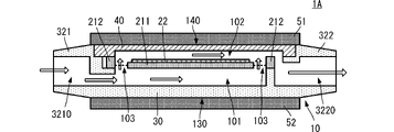
- FIG. 2 is a schematic side cross-sectional view including fluid flow of the pump device according to the first embodiment.
- FIG. 3 is a schematic graph showing an example of temperature change of a piezoelectric pump.
- FIG. 4 is a schematic side cross-sectional view including fluid flow of a pumping device according to a second embodiment.
- FIG. 5 is a schematic side view of a pump device according to a third embodiment;
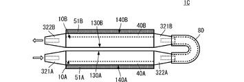
- FIG. 6 is a side view of the pump device according to the fourth embodiment.
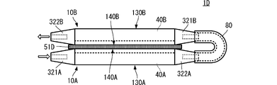
- FIG. 7 is a side view showing the configuration of the pump device according to the fifth embodiment.
- FIG. 1 is an exploded perspective view showing the configuration of the pump device according to the first embodiment.
- FIG. 2 is a schematic side cross-sectional view including fluid flow of the pump device according to the first embodiment.
- the shape of each constituent element is partially or wholly exaggerated in order to make the configuration of the pump device easier to understand.
- the pump device 1 includes a piezoelectric pump 10 and a heat storage member 51.
- the piezoelectric pump 10 includes a pump body 20, a base housing 30, and a lid member 40.
- the base housing 30 and the lid member 40 constitute the "housing" of the present invention.
- the pump body 20 includes a flat plate 211 , a frame 212 , a support portion 213 and a piezoelectric element 22 .
- the flat plate 211 is circular in plan view.
- the frame body 212 has a shape surrounding the outer peripheral edge of the flat plate 211 and is arranged at a position spaced apart from the outer peripheral edge of the flat plate 211 .
- the support portion 213 is arranged between the flat plate 211 and the frame 212 .
- the supporting portion 213 has a beam shape, and supports the flat plate 211 with respect to the frame 212 so as to be able to vibrate.
- the piezoelectric element 22 includes a disk-shaped piezoelectric body and a drive electrode.
- the piezoelectric element 22 is installed on one main surface of the flat plate 211 .
- a drive signal is applied to the piezoelectric element 22 by a drive signal application electrode 251 and a drive signal application electrode 252 .
- the base housing 30 includes a main member 31, a suction side nozzle 321, a discharge side nozzle 322, and a terminal mounting portion 35.
- the main member 31, the suction side nozzle 321, the discharge side nozzle 322, and the terminal mounting portion 35 are integrally molded, for example, from an insulating resin material.
- the main member 31 has a bottom wall 311 and side walls 312 .
- the main member 31 has a recess 33 surrounded by a bottom wall 311 and side walls 312 .
- the recessed portion 33 includes a central recessed portion 333 in plan view, a recessed portion 332 arranged on the outer periphery thereof, and a recessed portion 331 arranged on the outer periphery thereof and in contact with the inner edge of the side wall 312 .
- Recess 333 is deeper than recess 332
- recess 332 is deeper than recess 331 .
- the suction side nozzle 321 and the discharge side nozzle 322 are attached to the outer surface of the side wall 312 of the main member 31 .
- a suction port 3210 provided in the suction-side nozzle 321 communicates with the recessed portion 333 of the main member 31 through a through hole penetrating the side wall 312 in the thickness direction.
- a discharge port 3220 provided in the discharge-side nozzle 322 communicates with the concave portion 332 through a through-hole penetrating the side wall 312 in the thickness direction.
- the terminal mounting portion 35 is arranged at a position different from the position where the suction side nozzle 321 and the discharge side nozzle 322 are connected on the outer surface of the side wall 312 of the main member 31 .
- the terminal mounting portion 35 has a shape protruding outward from the side wall 312 of the main member 31 .
- One ends of the driving signal applying electrode 251 and the driving signal applying electrode 252 are placed on the terminal mounting portion 35 .
- the portions of the driving signal applying electrode 251 and the driving signal applying electrode 252 that are placed on the terminal mounting portion 35 serve as portions for supplying drive signals from the outside.
- the lid member 40 is a flat plate and is made of metal, for example.
- the outer shape of the lid member 40 is substantially the same as the inner shape of the side wall 312 of the base housing 30 , that is, the outer shape of the recess 331 .
- the lid member 40 may be made of resin, it is preferably made of a material having a higher thermal conductivity than the base housing 30, and is more preferably made of metal as described above.
- the pump body 20 is fitted into the recess 332 of the base housing 30 . More specifically, the pump main body 20 is fitted so that one main surface of the flat plate 211 on which the piezoelectric element 22 is installed is opposite to the concave portion 331 . At this time, the frame 212 contacts the surface of the concave portion 332 , and the flat plate 211 and the support portion 213 do not contact the concave portion 332 . That is, a suction-side space 101 is formed between the flat plate 211 and the support portion 213 and the surface of the recess 331, as shown in FIG.
- the lid member 40 is fitted into the recess 331 of the base housing 30 .
- a discharge side space 102 is formed between the lid member 40 and the flat plate 211 and the support portion 213 of the pump body 20 by adjusting the height of the recess 332. be.
- the pump body 20 is arranged so that the vibration of the flat plate 211 does not cause the flat plate 211 , the support portion 213 and the piezoelectric element 22 to come into contact with the lid member 40 .
- the pump body 20 is arranged in the internal space of the housing while the flat plate 211 can vibrate.
- the outer surface of the wall on the suction side space 101 side (corresponding to the “second wall” of the present invention) in the housing becomes the suction side outer wall surface 130, and the wall on the discharge side space 102 side (the “first wall” of the present invention). ) is the discharge-side outer wall surface 140 .
- the piezoelectric body of the piezoelectric element 22 is distorted and the flat plate 211 undergoes bending vibration.
- This bending vibration mainly changes the pressure distribution in the suction-side space 101 .
- fluid for example, air
- the fluid that has flowed into the suction side space 101 is conveyed to the discharge side space 102 through the communication port 103 between the support portions 213 .
- the fluid conveyed to the ejection-side space 102 is carried out to the ejection port 3220 of the ejection-side nozzle 322 and ejected to the outside.
- the driving of the piezoelectric element 22 causes the piezoelectric element 22 to generate heat, and the temperature of the internal space of the housing rises.
- the temperature of the discharge side space 102 on the downstream side in the fluid transport direction is likely to rise significantly.
- the heat storage member 51 has a flat plate shape with a predetermined thickness and has heat storage properties.
- the heat storage member 51 is preferably a latent heat storage material.
- the heat storage member 51 is a paraffin-based heat storage material, and normal paraffin, particularly nonadecane, icosane, henicosane, tetracosane, triacontane, etc., having a melting point of 30° C. to 70° C. are preferable.
- the heat storage member 51 is not limited to the latent heat storage material or the paraffin-based heat storage material, and any material that can keep the temperature within a certain temperature range for a predetermined time may be used.
- the heat storage density of the heat storage member 51 can be increased, and a constant temperature can be maintained for a longer period of time.
- a paraffin-based heat storage material it is possible to realize a weight reduction as well as a temperature retention capability.
- the heat storage member 51 is arranged on the discharge-side outer wall surface 140 of the housing of the piezoelectric pump 10 . At this time, the heat storage member 51 has a shape that covers the entire surface of the discharge-side outer wall surface 140 .
- the heat storage member 51 undergoes a phase change or phase transition by this heat, and stores the associated transition heat (latent heat) as thermal energy. As a result, the heat storage member 51 maintains a constant temperature over a predetermined length of time during which heat is applied.
- the temperature of the piezoelectric pump 10 in which the heat storage member 51 is installed is also stabilized at a constant temperature by the heat storage member 51 having a constant temperature.
- FIG. 3 is a schematic graph showing an example of temperature change of a piezoelectric pump.
- the horizontal axis is the elapsed time (time) from the start of driving of the piezoelectric element 22
- the vertical axis is the temperature of the piezoelectric pump 10 , more specifically the temperature of the discharge-side outer wall surface 140 .
- the solid line indicates the case of the configuration of the present invention (with the heat storage member), and the dashed line indicates the case of the comparative configuration (without the heat storage member).
- the temperature of the piezoelectric pump 10 is substantially constant over a predetermined period of time.
- the temperature of the piezoelectric pump 10 increases unilaterally with the passage of time.
- the pump device 1 can maintain the piezoelectric pump 10 at a predetermined temperature by installing the heat storage member 51 in the piezoelectric pump 10 . Thereby, the pump characteristics of the piezoelectric pump 10 can be stabilized.
- the pump device 1 can prevent the piezoelectric pump 10 from becoming hotter than the temperature determined by the heat storage member 51 .
- the thermal stress of the piezoelectric pump 10 can be reduced and the life of the piezoelectric pump 10 can be extended.
- the temperature determined by the heat storage member 51 is, for example, the temperature at which the phase changes from solid to liquid when the heat storage member 51 is a latent heat storage material. That is, the temperature determined by the heat storage member 51 is the temperature that the heat storage member 51 can keep within a certain temperature range for a predetermined time.
- the temperature of the discharge side space 102 tends to be higher than that of the suction side space 101 . Therefore, by arranging the heat storage member 51 on the discharge-side outer wall surface 140 of the piezoelectric pump 10, it is possible to effectively suppress a rise in temperature, and stabilize the temperature of the piezoelectric pump 10 more effectively.
- the heat storage member 51 is arranged on the entire surface of the discharge-side outer wall surface 140 .
- the heat storage effect described above is improved as compared with arranging the heat storage member 51 on a part of the discharge-side outer wall surface 140 .
- the heat storage member 51 can be provided on a portion of the discharge-side outer wall surface 140, the above-described heat storage effect can be obtained. Therefore, the temperature of the piezoelectric pump 10 can be stabilized more reliably.
- the heat storage member 51 may be arranged so as to overlap at least the piezoelectric element 22 when the pump device 1 is viewed from above.
- the main heat source is the piezoelectric element 22 . Therefore, by arranging the heat storage member 51 so as to overlap the piezoelectric element 22 , the heat storage member 51 can more efficiently and effectively store the heat generated in the piezoelectric pump 10 .
- the heat storage member 51 may be other heat storage material instead of latent heat storage material such as paraffin-based heat storage material.
- latent heat storage material the heat storage density of the heat storage member 51 can be increased, and the time for which a constant temperature is maintained can be lengthened.
- paraffin-based heat storage material the weight of the heat storage member 51 can be reduced. This makes it possible to realize a lightweight pump device 1 having stable pump characteristics.
- the heat storage member 51 preferably has flexibility. Accordingly, even if the lid member 40 vibrates due to the vibration of the flat plate 211 , the vibration can be absorbed by the heat storage member 51 . Thus, for example, the pump device 1 can suppress vibration noise.
- the heat storage member 51 has a similar shape to the discharge-side outer wall surface 140 , and further has a similar shape to the lid member 40 .
- vibrations are absorbed substantially uniformly in all azimuth directions around the piezoelectric element 22 in plan view. Therefore, the difference in vibration in each direction is suppressed, and the distortion occurring in the housing can be suppressed. As a result, the reliability of the pump device 1 is improved.
- the suction side nozzle 321 and the discharge side nozzle 322 are arranged on the side wall 312 of the housing.
- the opening surfaces of inlet 3210 and outlet 3220 do not directly face heat storage member 51 . Therefore, the influence of the sucked fluid and the discharged fluid on the heat storage member 51 can be suppressed. As a result, the temperature of the pump device 1 is more reliably stabilized, and stable pump performance can be more reliably achieved.
- FIG. 4 is a schematic side cross-sectional view including fluid flow of a pumping device according to a second embodiment.
- the pump device 1A according to the second embodiment differs from the pump device 1 according to the first embodiment in that a heat storage member 52 is added.
- Other configurations of the pump device 1A are the same as those of the pump device 1, and the description of the same parts is omitted.
- the pump device 1A includes a heat storage member 52.
- the heat storage member 52 is, for example, the same material as the heat storage member 51 .
- the heat storage member 52 may be made of a material different from that of the heat storage member 51 and may have a smaller heat storage capacity than the heat storage member 51 .
- the heat storage member 52 is arranged on the suction side outer wall surface 130 of the housing of the piezoelectric pump 10 . At this time, the heat storage member 52 has a shape that covers the entire surface of the suction side outer wall surface 130 .
- the pump device 1A can stabilize the temperature on the suction side of the piezoelectric pump 10 as well. Thereby, the pump device 1A can further stabilize the temperature of the piezoelectric pump 10 .
- the shape of the heat storage member 51 and the shape of the heat storage member 52 may be the same or different.
- FIG. 5 is a schematic side view of a pump device according to a third embodiment
- the pump device 1B according to the third embodiment differs from the pump device 1 according to the first embodiment in that a heat storage member 50 is provided.
- the rest of the configuration of the pump device 1B is the same as that of the pump device 1, and the description of the same portions will be omitted.
- the pump device 1B includes a heat storage member 50.
- the heat storage member 50 is made of the same material as the heat storage member 51 according to the first embodiment.
- the heat storage member 50 covers the outer surfaces of the suction-side outer wall surface 130 , the discharge-side outer wall surface 140 , and the side wall 312 of the piezoelectric pump 10 .
- the pump device 1B stores heat on both main surfaces and two side surfaces overlapping the piezoelectric elements 22 of the piezoelectric pump 10 . Therefore, the pump device 1B can further stabilize the temperature of the piezoelectric pump 10 .
- the heat storage member 50 is not arranged on the surface on which the suction side nozzle 321 and the discharge side nozzle 322 of the piezoelectric pump 10 are formed.
- the heat storage member 50 may also be arranged on the surface where the suction side nozzle 321 and the discharge side nozzle 322 of the piezoelectric pump 10 are formed.
- FIG. 6 is a side view of the pump device according to the fourth embodiment.
- the pump device 1C according to the fourth embodiment differs from the pump device 1 according to the first embodiment in that it includes a plurality of piezoelectric pumps and a plurality of heat storage members.
- the pump device 1C includes a piezoelectric pump 10A, a piezoelectric pump 10B, and a connection pipe 80.
- the piezoelectric pump 10A and the piezoelectric pump 10B have the same configuration as the piezoelectric pump 10 according to the first embodiment.
- the piezoelectric pump 10A and the piezoelectric pump 10B are connected by a connection pipe 80. More specifically, the discharge side nozzle 322A of the piezoelectric pump 10A and the suction side nozzle 321B of the piezoelectric pump 10B are connected by a connection pipe 80. As shown in FIG. The discharge port of the discharge-side nozzle 322A of the piezoelectric pump 10A and the suction port of the suction-side nozzle 321B of the piezoelectric pump 10B communicate with each other through the cavity of the connection pipe 80 .
- the piezoelectric pump 10A and the piezoelectric pump 10B are driven.
- the fluid is sucked into the piezoelectric pump 10A from the suction port of the suction side nozzle 321A of the piezoelectric pump 10A.
- the piezoelectric pump 10A discharges the sucked fluid to the connection pipe 80 from the discharge port of the discharge-side nozzle 322A of the piezoelectric pump 10A.
- the fluid discharged to the connecting pipe 80 is sucked into the piezoelectric pump 10B from the suction port of the suction side nozzle 321B of the piezoelectric pump 10B.
- the piezoelectric pump 10B discharges the sucked fluid to the outside from the discharge port of the discharge-side nozzle 322B of the piezoelectric pump 10B.
- the fluid is transported by the piezoelectric pump 10A and the piezoelectric pump 10B, so a larger flow rate can be achieved than when the piezoelectric pump 10A or the piezoelectric pump 10B is used alone.
- the piezoelectric pump 10A and the piezoelectric pump 10B are arranged such that the suction-side outer wall surface 130A of the piezoelectric pump 10A faces the suction-side outer wall surface 130B of the piezoelectric pump 10B. More specifically, the piezoelectric pump 10A and the piezoelectric pump 10B are such that the suction-side outer wall surface 130A of the piezoelectric pump 10A and the suction-side outer wall surface 130B of the piezoelectric pump 10B face each other, are close to each other, and are substantially parallel to each other. are placed so that
- the piezoelectric pump 10A is arranged so that the discharge-side outer wall surface 140A faces the side opposite to the piezoelectric pump 10B side.
- the piezoelectric pump 10B is arranged such that the discharge-side outer wall surface 140B faces the side opposite to the piezoelectric pump 10A side.
- the heat storage member 51A is arranged on the discharge side outer wall surface 140A of the piezoelectric pump 10A.
- the heat storage member 51B is arranged on the discharge side outer wall surface 140B of the piezoelectric pump 10B. That is, in the pump device 1C, heat storage members 51A and 51B are arranged for the plurality of piezoelectric pumps 10A and 10B, respectively.
- the pump device 1C can stabilize the temperature even if it has a plurality of piezoelectric pumps 10A and 10B each serving as a heat source.
- FIG. 7 is a side view showing the configuration of the pump device according to the fifth embodiment.
- the pump device 1D according to the fifth embodiment differs from the pump device 1C according to the fourth embodiment in the arrangement of the piezoelectric pumps 10A and 10B.
- the rest of the configuration of the pump device 1D is the same as that of the pump device 1C, and the description of the similar portions will be omitted.
- the piezoelectric pump 10A and the piezoelectric pump 10B are arranged so that the discharge-side outer wall surface 140A of the piezoelectric pump 10A and the discharge-side outer wall surface 140B of the piezoelectric pump 10B face each other, are close to each other, and are substantially parallel to each other. , is placed.
- the heat storage member 51D is sandwiched between the discharge-side outer wall surface 140A and the discharge-side outer wall surface 140B.
- the pump device 1D can stabilize the temperature even if it has a plurality of piezoelectric pumps 10A and 10B each serving as a heat source.
- piezoelectric pumps are provided.
- a configuration including three or more piezoelectric pumps may be used.
- an individual heat storage member may be arranged for each piezoelectric pump, or a common heat storage member may be arranged for a plurality of piezoelectric pumps.
- the heat storage member is directly brought into contact with the piezoelectric pump.
- the heat storage member does not have to be in direct contact with the piezoelectric pump.
- a thermally conductive adhesive layer may be placed between the heat storage member and the piezoelectric pump, or even if there is a gap between the piezoelectric pump and the heat storage member that allows heat to propagate from the piezoelectric pump to the heat storage member. good.
Landscapes
- Engineering & Computer Science (AREA)
- Mechanical Engineering (AREA)
- General Engineering & Computer Science (AREA)
- Reciprocating Pumps (AREA)
Abstract
Description
本発明の第1の実施形態に係るポンプ装置について、図を参照して説明する。図1は、第1の実施形態に係るポンプ装置の構成を示す分解斜視図である。図2は、第1の実施形態に係るポンプ装置の流体の流れを含む側断面の概略図である。なお、本実施形態を含む各実施形態に示す図は、ポンプ装置の構成を分かり易くするため、それぞれの構成要素の形状を部分的または全体として誇張して記載している。
本発明の第2の実施形態に係るポンプ装置について、図を参照して説明する。図4は、第2の実施形態に係るポンプ装置の流体の流れを含む側断面の概略図である。
本発明の第3の実施形態に係るポンプ装置について、図を参照して説明する。図5は、第3の実施形態に係るポンプ装置の概略側面図である。
本発明の第4の実施形態に係るポンプ装置について、図を参照して説明する。図6は、第4の実施形態に係るポンプ装置の側面図である。
本発明の第5の実施形態に係るポンプ装置について、図を参照して説明する。図7は、第5の実施形態に係るポンプ装置の構成を示す側面図である。
10、10A、10B:圧電ポンプ
20:ポンプ本体
22:圧電素子
30:ベース筐体
31:主部材
33、331、332、333:凹部
35:端子載置部
40:蓋部材
50、51、51A、51B、51D、52:蓄熱部材
80:接続管
101:吸引側空間
102:吐出側空間
103:連通口
130、130A、130B:吸入側外壁面
140、140A、140B:吐出側外壁面
211:平板
212:枠体
213:支持部
251、252:駆動信号印加電極
311:底壁
312:側壁
321、321A、321B:吸入側ノズル
322、322A、322B:吐出側ノズル
3210:吸入口
3220:吐出口
Claims (6)
- 一方主面に圧電素子が配置された平板、および、前記平板が内部に配置され前記平板を振動可能に支持する筐体を備える圧電ポンプと、
前記筐体に配置された蓄熱部材と、
を備える、ポンプ装置。 - 前記筐体は、前記平板を挟んで対向する第1壁と第2壁とを備え、
前記蓄熱部材は、前記第1壁と前記第2壁の少なくとも一方に配置される、
請求項1に記載のポンプ装置。 - 前記第1壁は、前記平板の前記一方主面に対向し、
前記蓄熱部材は、前記第1壁に配置される、
請求項2に記載のポンプ装置。 - 前記平板の一方主面から他方主面方向に平面視して、前記蓄熱部材は、圧電素子に重なる位置に配置される、
請求項3に記載のポンプ装置。 - 前記蓄熱部材は、潜熱蓄熱材である、
請求項1乃至請求項4のいずれかに記載のポンプ装置。 - 前記蓄熱部材は、パラフィン系蓄熱材である、
請求項5に記載のポンプ装置。
Priority Applications (2)
| Application Number | Priority Date | Filing Date | Title |
|---|---|---|---|
| CN202180086396.4A CN116635632A (zh) | 2021-02-16 | 2021-11-29 | 泵装置 |
| JP2023500546A JP7416324B2 (ja) | 2021-02-16 | 2021-11-29 | ポンプ装置 |
Applications Claiming Priority (2)
| Application Number | Priority Date | Filing Date | Title |
|---|---|---|---|
| JP2021022350 | 2021-02-16 | ||
| JP2021-022350 | 2021-02-16 |
Publications (1)
| Publication Number | Publication Date |
|---|---|
| WO2022176306A1 true WO2022176306A1 (ja) | 2022-08-25 |
Family
ID=82931374
Family Applications (1)
| Application Number | Title | Priority Date | Filing Date |
|---|---|---|---|
| PCT/JP2021/043567 Ceased WO2022176306A1 (ja) | 2021-02-16 | 2021-11-29 | ポンプ装置 |
Country Status (3)
| Country | Link |
|---|---|
| JP (1) | JP7416324B2 (ja) |
| CN (1) | CN116635632A (ja) |
| WO (1) | WO2022176306A1 (ja) |
Families Citing this family (2)
| Publication number | Priority date | Publication date | Assignee | Title |
|---|---|---|---|---|
| JP7435894B2 (ja) * | 2021-02-22 | 2024-02-21 | 株式会社村田製作所 | ポンプ装置 |
| CN119616834B (zh) * | 2024-11-01 | 2025-10-28 | 广东奥迪威传感科技股份有限公司 | 压电泵散热装置 |
Citations (4)
| Publication number | Priority date | Publication date | Assignee | Title |
|---|---|---|---|---|
| WO2017108628A1 (en) * | 2015-12-23 | 2017-06-29 | Alcatel Lucent | A fluidic pump |
| JP2019171312A (ja) * | 2018-03-29 | 2019-10-10 | 日本電産株式会社 | 液剤塗布装置 |
| WO2020188966A1 (ja) * | 2019-03-18 | 2020-09-24 | 株式会社村田製作所 | ポンプユニット |
| WO2020261686A1 (ja) * | 2019-06-27 | 2020-12-30 | 株式会社村田製作所 | ポンプ装置 |
Family Cites Families (7)
| Publication number | Priority date | Publication date | Assignee | Title |
|---|---|---|---|---|
| JP2011144695A (ja) * | 2010-01-12 | 2011-07-28 | Panasonic Corp | 蓄熱装置、ならびにこれを備えた空気調和機 |
| EP2812575B1 (en) * | 2012-02-10 | 2020-04-01 | KCI Licensing, Inc. | Systems and methods for regulating the temperature of a disc pump system |
| JP2013229894A (ja) | 2013-06-07 | 2013-11-07 | Olympus Imaging Corp | 撮像素子モジュール、撮像素子モジュールを用いたレンズユニット及び携帯用電子機器 |
| DE102014225411A1 (de) * | 2014-12-10 | 2016-06-16 | Mahle International Gmbh | Sorptionsmodul |
| JP2017106645A (ja) * | 2015-12-07 | 2017-06-15 | 株式会社フジクラ | 冷却装置 |
| CN211737429U (zh) * | 2017-08-25 | 2020-10-23 | 研能科技股份有限公司 | 致动气体导流装置 |
| CN107906992A (zh) * | 2017-11-03 | 2018-04-13 | 珠海格力电器股份有限公司 | 一种蓄热器和空调器 |
-
2021
- 2021-11-29 WO PCT/JP2021/043567 patent/WO2022176306A1/ja not_active Ceased
- 2021-11-29 CN CN202180086396.4A patent/CN116635632A/zh active Pending
- 2021-11-29 JP JP2023500546A patent/JP7416324B2/ja active Active
Patent Citations (4)
| Publication number | Priority date | Publication date | Assignee | Title |
|---|---|---|---|---|
| WO2017108628A1 (en) * | 2015-12-23 | 2017-06-29 | Alcatel Lucent | A fluidic pump |
| JP2019171312A (ja) * | 2018-03-29 | 2019-10-10 | 日本電産株式会社 | 液剤塗布装置 |
| WO2020188966A1 (ja) * | 2019-03-18 | 2020-09-24 | 株式会社村田製作所 | ポンプユニット |
| WO2020261686A1 (ja) * | 2019-06-27 | 2020-12-30 | 株式会社村田製作所 | ポンプ装置 |
Also Published As
| Publication number | Publication date |
|---|---|
| JPWO2022176306A1 (ja) | 2022-08-25 |
| JP7416324B2 (ja) | 2024-01-17 |
| CN116635632A (zh) | 2023-08-22 |
Similar Documents
| Publication | Publication Date | Title |
|---|---|---|
| US11598330B2 (en) | Fluid control device and pump | |
| US9028226B2 (en) | Fluid control device | |
| CN102979703B (zh) | 流体控制装置 | |
| JP7485002B2 (ja) | ポンプ装置 | |
| JP5177331B1 (ja) | ポンプ装置 | |
| US10626861B2 (en) | Blower | |
| CN112204256A (zh) | 泵 | |
| JP7416324B2 (ja) | ポンプ装置 | |
| JP6319517B2 (ja) | ポンプ | |
| US12467447B2 (en) | First and second piezoelectric pumps and connection pipe arrangement | |
| WO2020195075A1 (ja) | 圧電ポンプ | |
| WO2013187270A1 (ja) | ブロア | |
| JP7409518B2 (ja) | 流体制御装置 | |
| JP7616233B2 (ja) | 流体制御装置 | |
| WO2024195204A1 (ja) | 流体制御装置 | |
| CN114208212B (zh) | 压电发声部件用外壳以及压电发声部件 | |
| JP2023126991A (ja) | ポンプ及び流体制御装置 |
Legal Events
| Date | Code | Title | Description |
|---|---|---|---|
| 121 | Ep: the epo has been informed by wipo that ep was designated in this application |
Ref document number: 21926734 Country of ref document: EP Kind code of ref document: A1 |
|
| ENP | Entry into the national phase |
Ref document number: 2023500546 Country of ref document: JP Kind code of ref document: A |
|
| WWE | Wipo information: entry into national phase |
Ref document number: 202180086396.4 Country of ref document: CN |
|
| NENP | Non-entry into the national phase |
Ref country code: DE |
|
| 122 | Ep: pct application non-entry in european phase |
Ref document number: 21926734 Country of ref document: EP Kind code of ref document: A1 |