WO2022176193A1 - 電解コンデンサ寿命判定装置およびモータ駆動装置 - Google Patents
電解コンデンサ寿命判定装置およびモータ駆動装置 Download PDFInfo
- Publication number
- WO2022176193A1 WO2022176193A1 PCT/JP2021/006596 JP2021006596W WO2022176193A1 WO 2022176193 A1 WO2022176193 A1 WO 2022176193A1 JP 2021006596 W JP2021006596 W JP 2021006596W WO 2022176193 A1 WO2022176193 A1 WO 2022176193A1
- Authority
- WO
- WIPO (PCT)
- Prior art keywords
- electrolytic capacitor
- value
- voltage
- life
- measured
- Prior art date
- Legal status (The legal status is an assumption and is not a legal conclusion. Google has not performed a legal analysis and makes no representation as to the accuracy of the status listed.)
- Ceased
Links
Images


Classifications
-
- G—PHYSICS
- G01—MEASURING; TESTING
- G01R—MEASURING ELECTRIC VARIABLES; MEASURING MAGNETIC VARIABLES
- G01R27/00—Arrangements for measuring resistance, reactance, impedance, or electric characteristics derived therefrom
- G01R27/02—Measuring real or complex resistance, reactance, impedance, or other two-pole characteristics derived therefrom, e.g. time constant
- G01R27/26—Measuring inductance or capacitance; Measuring quality factor, e.g. by using the resonance method; Measuring loss factor; Measuring dielectric constants ; Measuring impedance or related variables
-
- G—PHYSICS
- G01—MEASURING; TESTING
- G01R—MEASURING ELECTRIC VARIABLES; MEASURING MAGNETIC VARIABLES
- G01R31/00—Arrangements for testing electric properties; Arrangements for locating electric faults; Arrangements for electrical testing characterised by what is being tested not provided for elsewhere
Definitions
- the present disclosure relates to an electrolytic capacitor life determination device and a motor drive device for estimating the life of an electrolytic capacitor of a motor drive device.
- a motor drive device uses an inverter circuit that converts a DC voltage into an AC voltage in order to control the rotation speed or torque of the motor.
- the AC voltage applied from the AC power supply is once converted to DC by the rectifier diode bridge circuit and the boost converter circuit.
- the inverter circuit switches a bus voltage by a switching circuit including a switching element arranged between the DC bus lines to generate drive power for the motor.
- the bus voltage in this switching circuit is a DC voltage stabilized by removing the ripple component of the DC voltage rectified by the boost converter circuit with a smoothing electrolytic capacitor.
- the ripple current contained in the output current of the converter circuit and the ripple current generated by the inverter circuit flow into the capacitor, which generates heat, and the life of the smoothing electrolytic capacitor deteriorates according to the Arrhenius law due to thermal stress.
- Patent Document 1 discloses a current detection device that measures ripple current charged and discharged in a smoothing electrolytic capacitor during motor operation, a temperature detection device that measures the ambient temperature of the smoothing electrolytic capacitor, and a ripple current measured by the current detection device.
- a life determination device for a smoothing electrolytic capacitor of an inverter device is disclosed, which includes a diagnostic device for determining the remaining life of the smoothing electrolytic capacitor based on a current value and an ambient temperature measured by a temperature detection device.
- the present disclosure has been made in view of the above, and provides an electrolytic capacitor life determination device that can reduce the number of parts of a motor drive device compared to the conventional one and can suppress the increase in size of the motor drive device. With the goal.
- the present disclosure provides a single-phase or three-phase AC power supply and a motor for a motor drive device including a voltage detection unit that measures a DC voltage used for motor drive control. It is an electrolytic capacitor life determination device for determining the life of an electrolytic capacitor connected between.
- the electrolytic capacitor life determination device consists of a current detection unit that measures the ripple current flowing through the electrolytic capacitor, a ripple current measurement value that is the value of the ripple current measured by the current detection unit, and a DC voltage measured by the voltage detection unit. and a diagnosing unit that obtains the remaining life of the electrolytic capacitor by using the DC voltage actual measurement value.
- the electrolytic capacitor life determination device has the effect of reducing the number of parts of the motor drive device compared to the conventional one and suppressing the enlargement of the motor drive device.
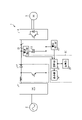
- FIG. 1 is a diagram schematically showing an example of a circuit configuration of a motor drive device including the electrolytic capacitor life determination device according to Embodiment 1;
- FIG. 5 is a diagram schematically showing an example of a circuit configuration of a motor drive device including an electrolytic capacitor life determination device according to Embodiment 2;
- FIG. 10 is a diagram schematically showing an example of a circuit configuration of a motor drive device including an electrolytic capacitor life determination device according to Embodiment 3;
- FIG. 11 is a diagram schematically showing another example of the circuit configuration of a motor drive device including the electrolytic capacitor life determination device according to Embodiment 3;
- FIG. 2 is a block diagram schematically showing an example of hardware configuration of a diagnosis unit and a control unit provided in the electrolytic capacitor life determination device according to Embodiments 1 to 3;
- FIG. 11 is a diagram schematically showing another example of the circuit configuration of a motor drive device including the electrolytic capacitor life determination device according to Embodiment 3;
- FIG. 2 is a block diagram schematically showing an example of hardware configuration of a diagnosis unit and a control unit provided in the electrolytic capacitor life determination device according to Embodiments 1 to 3;
- FIG. 1 is a diagram schematically showing an example of a circuit configuration of a motor drive device including an electrolytic capacitor life determination device according to Embodiment 1.
- the motor drive device 1 includes a diode bridge circuit 11 , a boost converter circuit 12 , a smoothing electrolytic capacitor 13 , an inverter circuit 14 and a voltage detector 15 .
- motor drive device 1 is configured by mounting diode bridge circuit 11, boost converter circuit 12, smoothing electrolytic capacitor 13, and inverter circuit 14 on a substrate.
- the diode bridge circuit 11 is connected to the AC power supply 2 and the smoothing electrolytic capacitor 13 .
- Smoothing electrolytic capacitor 13 is connected to boost converter circuit 12 and inverter circuit 14 .
- the inverter circuit 14 is connected to the boost converter circuit 12 , the smoothing electrolytic capacitor 13 and the motor 3 .
- the diode bridge circuit 11 has the function of a converter circuit, and rectifies the AC voltage applied from the AC power supply 2 and converts it into a DC voltage.
- An example of the AC power supply 2 is a three-phase commercial AC power supply that outputs a three-phase AC voltage or a single-phase commercial AC power supply that outputs a single-phase AC voltage.
- the diode bridge circuit 11 corresponds to the rectifier circuit section.
- the boost converter circuit 12 is a circuit that boosts the DC voltage output from the diode bridge circuit 11 to, for example, double the DC voltage. That is, an example of the boost converter circuit 12 is a voltage doubler circuit. Note that the boost converter circuit 12 may boost the voltage output from the diode bridge circuit 11 to a multiple other than double, such as 1.5 times or 4 times. That is, the boost converter circuit 12 may boost the DC voltage by any number of times as long as it boosts the DC voltage to be higher than the DC voltage output from the diode bridge circuit 11 .
- the smoothing electrolytic capacitor 13 stores the charge sent from the boost converter circuit 12 and smoothes the rectified DC voltage.
- the electric charge output from the boost converter circuit 12 is accumulated in the smoothing electrolytic capacitor 13, and the accumulated electric charge is supplied to the inverter circuit 14, thereby converting the DC voltage output from the diode bridge circuit 11. is supplied to the inverter circuit 14 in a boosted state.
- the smoothing electrolytic capacitor 13 corresponds to an electrolytic capacitor.
- the inverter circuit 14 converts the DC voltage smoothed by the smoothing electrolytic capacitor 13 into AC voltage and applies it to the motor 3 .
- power is supplied to the motor 3 from the smoothing electrolytic capacitor 13 through the inverter circuit 14 .
- the voltage detection unit 15 is provided after the boost converter circuit 12 and measures the DC voltage applied to the smoothing electrolytic capacitor 13 .
- the voltage detection section 15 is a component generally used for motor control and overvoltage protection of the DC section, and is generally provided in the motor drive device 1 .
- the DC section is a section in the motor drive device 1 where the voltage is DC, and is a section from the rear stage of the diode bridge circuit 11 to the front stage of the inverter circuit 14 .
- the voltage detection unit 15 outputs the DC voltage actual measurement value Vdc , which is the value of the measured DC voltage, to the diagnosis unit 22 described later.
- the motor drive device 1 includes an electrolytic capacitor life determination device 20 that determines the life of the smoothing electrolytic capacitor 13 connected between the AC power supply 2 and the motor 3 .
- the electrolytic capacitor life determination device 20 has a current detection section 21 , a diagnosis section 22 , a storage section 23 and a display section 24 .
- the current detection unit 21 measures the ripple current flowing into the smoothing electrolytic capacitor 13 and outputs to the diagnosis unit 22 a ripple current actual measurement value i c act that is the value of the measured ripple current.
- the current detector 21 is provided on the connection line of the smoothing electrolytic capacitor 13 .
- Diagnosis unit 22 uses the actual ripple current value i c act measured by current detection unit 21 and the actual DC voltage value V dc measured by voltage detection unit 15 to determine the remaining life of smoothing electrolytic capacitor 13. Ask for Specifically, the diagnosis unit 22 uses the measured DC voltage value V dc and the measured ripple current value i c act to determine the measured capacitance value C current Calculate In addition, the diagnosis unit 22 calculates the amount of change in the capacitance value C current during measurement, and based on the capacitor life correlation information indicating the relationship between the change in capacitance value and the remaining life, the static electricity during measurement Obtain the remaining life corresponding to the amount of change in the capacitance value Ccurrent . The diagnosis unit 22 determines the life of the smoothing electrolytic capacitor 13 by comparing the remaining life with a threshold that is a reference value for determining that the smoothing electrolytic capacitor 13 has reached the end of its life.
- the diagnosis unit 22 calculates a ripple current estimated value i c est , which is an estimated value of the ripple current, from the DC voltage actual measurement value V dc using the following equation (1).
- C initial is the initial capacitance value of the smoothing electrolytic capacitor 13 .
- Diagnosis unit 22 calculates capacitance value C current during measurement of smoothing electrolytic capacitor 13 during measurement using the following equation (2) from ripple current estimated value i c est and ripple current actual measurement value i c act .
- the diagnosis unit 22 stores the measured capacitance value C current in the storage unit 23 .
- the diagnosis unit 22 stores the capacitance value C current at measurement in the storage unit 23 in association with the time when the DC voltage actual measurement value V dc is measured and the DC voltage actual measurement value V dc .
- Time-series data of the measured capacitance value C current is stored in the storage unit 23 .
- the diagnosis unit 22 calculates the capacitance change of the smoothing electrolytic capacitor 13 due to deterioration from the time-series data of the capacitance value C current during measurement stored in the storage unit 23 . Calculation of capacitance change is performed by a predetermined method. In one example, the capacitance change is calculated based on the capacitance value C current at the time of measurement in the initial stage. The diagnosis unit 22 acquires the remaining life of the smoothing electrolytic capacitor 13 corresponding to the calculated change in capacitance by referring to the capacitor life correlation information.
- the capacitor life correlation information is information indicating the relationship between the difference between the capacitance value and the measured capacitance value C current in the initial stage, and the remaining life of the smoothing electrolytic capacitor 13 at this time. is.
- Diagnosis unit 22 compares the remaining life with a threshold, determines that smoothing electrolytic capacitor 13 has not reached the end of its life when the remaining life is greater than the threshold, and determines that the remaining life is less than the threshold. It is determined that the smoothing electrolytic capacitor 13 has reached the end of its life.
- the diagnosis unit 22 also displays the diagnosis result, which is information about the remaining life, on the display unit 24 . When the remaining life is equal to the threshold value, it may be determined that the life is not reached or that the life is reached. For example, when the smoothing electrolytic capacitor 13 has reached the end of its life, the diagnosis unit 22 displays information indicating that the life has expired on the display unit 24 . In one example, the diagnostic unit 22 may display the remaining life on the display unit 24 when the smoothing electrolytic capacitor 13 has not reached the end of its life.
- the diagnosis unit 22 compares the ripple current actual measurement value i c act and the ripple current estimated value i c est of the smoothing electrolytic capacitor 13 at the initial stage. , the deviation of the capacitance of the smoothing electrolytic capacitor 13 from the nominal value may be calculated, and the above calculation may be corrected using this deviation.
- the storage unit 23 stores the DC voltage actual measurement value V dc and the capacitance value C current at the time of measurement in association with the time when the DC voltage actual measurement value V dc was measured. Note that the storage unit 23 may store other information. In one example, the storage unit 23 may store the initial capacitance value C initial . The initial capacitance value C initial is referred to by the diagnostic unit 22 .
- the display unit 24 is a display device capable of displaying information.
- the display unit 24 is a liquid crystal display.
- the display unit 24 displays the diagnosis result of the service life of the smoothing electrolytic capacitor 13 received from the diagnosis unit 22 .
- FIG. 2 is a flow chart showing an example of the procedure of the life determination method for the smoothing electrolytic capacitor according to the first embodiment.
- the voltage detection unit 15 measures the DC voltage actual value Vdc (step S12) and outputs the DC voltage actual value Vdc to the diagnostic unit 22 .
- the diagnosis unit 22 calculates the ripple current estimated value i c est according to the equation (1) (step S13).
- the ripple current estimated value i c est is calculated by differentiating the measured DC voltage value V dc with respect to time.
- the ripple current estimated value i c est is calculated using the DC voltage actual measurement value V dc .
- the voltage detection unit 15 stores the calculated DC voltage actual measurement value V dc in the storage unit 23 together with the measurement time.
- the current detection unit 21 measures the actual ripple current value i cact (step S ⁇ b>14 ) and outputs the actual ripple current value i cact to the diagnosis unit 22 .
- the processing of steps S12 to S13 and the processing of step S14 may be performed in parallel.
- the diagnostic unit 22 calculates the measured capacitance value C current of the smoothing electrolytic capacitor 13 according to the equation (2) from the estimated ripple current value i c est and the measured ripple current value i c act .
- the current capacitance value Ccurrent is stored in the storage unit 23 (step S15).
- the calculated measured capacitance value C current is stored in the storage unit 23 in association with the measurement time of the DC voltage actual measurement value V dc used to calculate the ripple current estimated value i c est .
- the diagnosis unit 22 determines whether the motor driving device 1 is in the initial operation (step S16). If it is the initial operation of the motor drive device 1 (Yes in step S16), the diagnosis unit 22 stores the initial electrostatic capacitance value C initial of the smoothing electrolytic capacitor 13 in the storage unit 23 (step S17). . At this time, by comparing the ripple current actual measurement value i c act and the ripple current estimated value i c est in the initial stage of the smoothing electrolytic capacitor 13, the initial capacitance value C initial of the smoothing electrolytic capacitor 13 A deviation from the nominal value is calculated, and the nominal value of the initial capacitance value C initial of the smoothing electrolytic capacitor 13 is corrected using the calculated deviation. When the correction is performed, the corrected initial capacitance value C initial of the smoothing electrolytic capacitor 13 is used in the process of transition. If the initial capacitance value C initial of the smoothing electrolytic capacitor 13 does not deviate from the nominal value, no correction is performed.
- the diagnosis unit 22 calculates the capacitance change from the capacitance stored in the storage unit 23. (step S18).
- the diagnosis unit 22 refers to the capacitor life correlation information and acquires the remaining life of the smoothing electrolytic capacitor 13 corresponding to the calculated change in capacitance (step S19).
- the capacitor life correlation information is, for example, information obtained by calculating the correlation between the capacitance change from the initial capacitance value C initial and the remaining life of the smoothing electrolytic capacitor 13 .
- the diagnosis unit 22 determines whether the acquired remaining life is equal to or less than a threshold (step S20).
- the threshold is a reference value for determining that the smoothing electrolytic capacitor 13 has reached the end of its life. If the remaining life is not equal to or less than the threshold (No in step S20), the smoothing electrolytic capacitor 13 has not reached the end of its life, and the process returns to step S12. If the remaining life is equal to or less than the threshold (Yes in step S20), the smoothing electrolytic capacitor 13 has reached the end of its life. (step S21). With the above, the processing ends.
- the obtained remaining life may be displayed on the display unit 24 when the remaining life is not equal to or less than the threshold in step S20 (No in step S20). This allows the user of the motor drive device 1 to easily grasp the remaining life of the smoothing electrolytic capacitor 13 .
- the diagnostic unit 22 detects the remaining amount of the smoothing electrolytic capacitor 13 based on the ripple current actual measurement value i c act and the ripple current estimated value i c est of the smoothing electrolytic capacitor 13 . I started looking for life.
- the current detection unit 21 is provided without simultaneously providing the current detection unit 21 for detecting the ripple current and the temperature detection device for measuring the ambient temperature of the smoothing electrolytic capacitor 13 in the motor drive device 1 as in the conventional art.
- the life of the smoothing electrolytic capacitor 13 can be determined only by That is, there is an effect that the number of parts of the motor driving device 1 can be reduced as compared with the conventional art, and an increase in the size of the motor driving device 1 can be suppressed.
- the measured ripple current value i c act and the estimated ripple current value i c est are compared, and from the nominal value of the initial capacitance value C initial of the smoothing electrolytic capacitor 13, is calculated, and the calculated result is used to correct the initial capacitance value C initial . That is, by calculating the ripple current estimated value i c est of the smoothing electrolytic capacitor 13 from the DC voltage actual value V dc , there is no need to adjust the initial ripple current to the recorded operating conditions when calculating the service life. Even if the electrostatic capacitance of the smoothing electrolytic capacitor 13 deviates from the nominal value in the initial stage, the initial electrostatic capacitance value C initial can be corrected. has the effect of enabling the calculation of
- FIG. 3 is a diagram schematically showing an example of a circuit configuration of a motor drive device including an electrolytic capacitor life determination device according to Embodiment 2.
- a motor drive device 1A of the second embodiment includes an electrolytic capacitor life determination device 20A having a configuration different from that of the first embodiment. That is, electrolytic capacitor life determination device 20A eliminates current detection unit 21 from electrolytic capacitor life determination device 20 of the first embodiment, and further includes temperature detection unit 25 that measures the ambient temperature of smoothing electrolytic capacitor 13 .
- the temperature detection unit 25 outputs the ambient temperature actual measurement value Tx, which is the measured temperature value, to the diagnosis unit 22 .
- the diagnosis unit 22 uses the measured ambient temperature value Tx of the smoothing electrolytic capacitor 13 measured by the temperature detection unit 25 and the DC voltage actual value V dc measured by the voltage detection unit 15 to determine the smoothing electrolytic capacitor Find the remaining life of 13. Specifically, the diagnosis unit 22 calculates the ripple current estimated value i c est using the DC voltage actual measurement value V dc and the initial capacitance value C initial of the smoothing electrolytic capacitor 13 . Diagnosis unit 22 calculates remaining life L x , which is an estimated life of smoothing electrolytic capacitor 13 , based on ripple current estimated value i c est and ambient temperature actual measurement value Tx. The diagnosis unit 22 determines the life of the smoothing electrolytic capacitor 13 by comparing the remaining life L x with a threshold value that is a reference value for determining that the smoothing electrolytic capacitor 13 has reached the end of its life.
- the diagnosis unit 22 calculates the ripple current estimated value i c est from the DC voltage actual measurement value V dc using equation (1).
- the diagnosis unit 22 uses the ripple current estimated value i c est and the ambient temperature actual measurement value Tx detected by the temperature detection unit 25 to determine the temperature change ⁇ T[ °C] is calculated using the following equation (3). Assume that the internal resistance of the smoothing electrolytic capacitor 13 is R [ ⁇ ], the heat radiation constant of the smoothing electrolytic capacitor 13 is ⁇ , and the case surface area of the smoothing electrolytic capacitor 13 is A [m 2 ].
- the diagnostic unit 22 calculates the remaining life Lx under the operating conditions when the measured DC voltage value Vdc and the measured ambient temperature value Tx are detected using the following equation (4).
- the specified life of the smoothing electrolytic capacitor 13 when the rated voltage is applied at the maximum operating temperature is Lo [hours]
- the maximum operating temperature of the smoothing electrolytic capacitor 13 is To [ ° C].
- the maximum use temperature is also referred to as the upper category temperature.
- Diagnosis unit 22 compares remaining life L x with a threshold, and if remaining life L x is greater than the threshold, determines that smoothing electrolytic capacitor 13 has reached the end of its life, and remaining life L x exceeds the threshold. is small, it is determined that the smoothing electrolytic capacitor 13 has reached the end of its life. Further, the diagnosis unit 22 displays the diagnosis result, which is information about the remaining life L x , on the display unit 24 . When the remaining life L x is equal to the threshold value, it may be determined that the life is not reached or that the life is reached. For example, when the smoothing electrolytic capacitor 13 has reached the end of its life, the diagnosis unit 22 displays information indicating that the life has expired on the display unit 24 . Further, as an example, the diagnosis unit 22 may display the remaining life L x on the display unit 24 when the smoothing electrolytic capacitor 13 has not reached the end of its life.
- FIG. 4 is a flow chart showing an example of the procedure of the life determination method for the smoothing electrolytic capacitor according to the second embodiment.
- the voltage detection unit 15 measures the DC voltage actual value Vdc (step S32) and outputs the DC voltage actual value Vdc to the diagnostic unit 22 .
- the diagnosis unit 22 calculates the ripple current estimated value i c est according to the equation (1) (step S33).
- the voltage detection unit 15 stores the calculated DC voltage actual measurement value Vdc in the storage unit 23 together with the measurement time.
- the temperature detection unit 25 measures the ambient temperature actual measurement value Tx of the smoothing electrolytic capacitor 13 (step S34), and outputs the ambient temperature actual measurement value Tx to the diagnostic unit 22.
- the processing of steps S32 to S33 and the processing of step S34 may be performed in parallel.
- diagnosis unit 22 calculates the remaining life L x is calculated, and the calculated remaining life L x is stored in the storage unit 23 (step S35).
- the diagnosis unit 22 determines whether the remaining life L x is equal to or less than the threshold (step S36).
- the threshold is a reference value for determining that the smoothing electrolytic capacitor 13 has reached the end of its life. If the remaining life L x is not equal to or less than the threshold (No in step S36), the diagnostic unit 22 determines that the smoothing electrolytic capacitor 13 has not reached the end of its life, and the process returns to step S32. If the remaining life L x is equal to or less than the threshold (Yes in step S36), the smoothing electrolytic capacitor 13 has reached the end of its life. (step S37). With the above, the processing ends.
- the acquired remaining life L x may be displayed on the display unit 24 when the remaining life L x is not equal to or less than the threshold in step S36 (No in step S36). This allows the user of the motor drive device 1A to easily grasp the remaining life L x of the smoothing electrolytic capacitor 13 .
- the diagnosis unit 22 calculates the estimated ripple current value i c est from the measured DC voltage value V dc of the smoothing electrolytic capacitor 13, and calculates the estimated ripple current value i c est . Based on the ambient temperature Tx of the smoothing electrolytic capacitor 13 detected by the temperature detector 25, the remaining life Lx of the smoothing electrolytic capacitor 13 is calculated. As a result, the temperature detection unit 25 is provided without simultaneously providing the current detection unit 21 for detecting the current and the temperature detection unit 25 for measuring the ambient temperature of the smoothing electrolytic capacitor 13 in the motor drive device 1A as in the conventional art.
- the life of the smoothing electrolytic capacitor 13 can be determined only by That is, there is an effect that the number of parts of the motor driving device 1A can be reduced as compared with the conventional one, and an increase in the size of the motor driving device 1A can be suppressed.
- the diagnostic unit 22 calculates the remaining life L x of the smoothing electrolytic capacitor 13 using the equations (3) and (4), and displays the result on the display unit 24 .
- the user can easily understand how much the smoothing electrolytic capacitor 13 has deteriorated and how long the remaining life L x is by looking at the value on the display unit 24 .
- the user can easily grasp the life state of the smoothing electrolytic capacitor 13 .
- FIG. 5 is a diagram schematically showing an example of a circuit configuration of a motor drive device including an electrolytic capacitor life determination device according to Embodiment 3.
- a motor drive device 1B according to the third embodiment includes an electrolytic capacitor life determination device 20B having a configuration different from that of the first embodiment. That is, when the remaining life of the smoothing electrolytic capacitor 13 becomes equal to or less than the limit execution value, which is a predetermined value, based on the determination of the life of the electrolytic capacitor by the diagnostic unit 22, the electrolytic capacitor life determination device 20B limits the boost converter circuit 12. is further provided with a control unit 26 for applying .
- the diagnosis unit 22 outputs the calculated remaining life of the smoothing electrolytic capacitor 13 to the control unit 26 .
- the control unit 26 limits the boosting of the boost converter circuit 12 based on the remaining life of the smoothing electrolytic capacitor 13 from the diagnosis unit 22 . That is, when the remaining life calculated by the diagnostic unit 22 becomes smaller than the limit execution value, the control unit 26 limits the value of the voltage boosted by the boost converter circuit 12 to be low. In this manner, when smoothing electrolytic capacitor 13 approaches the end of its life, control unit 26 performs control to extend the life of smoothing electrolytic capacitor 13 .
- the DC voltage boosted by the boost converter circuit 12 decreases, the effective value of the AC voltage converted by the inverter circuit 14 also decreases, so the current flowing through the motor 3 increases. can be prolonged.
- the boost converter circuit 12 by limiting the boost converter circuit 12, the voltage fluctuation is reduced, and as a result, the ripple current is also reduced. As a result, deterioration of the smoothing electrolytic capacitor 13 is reduced, and the life of the smoothing electrolytic capacitor 13 before it is determined to be faulty is lengthened. Therefore, it is possible to extend the life of the product.
- FIG. 5 shows the configuration in which the motor drive device 1 of the first embodiment is provided with the control section 26, the control section 26 may be provided in the motor drive device 1A of the second embodiment.
- FIG. 6 is a diagram schematically showing another example of the circuit configuration of the motor drive device including the electrolytic capacitor life determination device according to the third embodiment.
- the electrolytic capacitor life determination device 20C of the motor drive device 1C shown in FIG. A control unit 26 for limiting is further provided. Note that the functions of the control unit 26 in FIG. 6 are the same as those described in FIG.
- the control unit limits the boosting of the boost converter circuit 12. 26. This makes it possible to extend the life of the smoothing electrolytic capacitor 13 without limiting the inverter outputs of the motor driving devices 1B and 1C.
- the diagnostic unit 22 and the control unit 26 of Embodiments 1 to 3 are implemented as processing circuits.
- the processing circuit may be dedicated hardware, or may be a circuit with a processor.
- FIG. 7 is a block diagram schematically showing an example of a hardware configuration of a diagnosis section and a control section provided in the electrolytic capacitor life determination devices according to Embodiments 1 to 3.
- FIG. Diagnosis unit 22 and control unit 26 have processor 501 and memory 502 . Processor 501 and memory 502 are connected via bus line 503 . Diagnosis unit 22 and control unit 26 are implemented by processor 501 executing a program stored in memory 502 . Also, multiple processors and multiple memories may work together to achieve the above functions. Also, some of the functions of the diagnosis unit 22 and the control unit 26 may be implemented as an electronic circuit, which is dedicated hardware, and other parts may be implemented using the processor 501 and the memory 502 .
Landscapes
- Physics & Mathematics (AREA)
- General Physics & Mathematics (AREA)
- Testing Electric Properties And Detecting Electric Faults (AREA)
- Measurement Of Resistance Or Impedance (AREA)
Priority Applications (2)
| Application Number | Priority Date | Filing Date | Title |
|---|---|---|---|
| PCT/JP2021/006596 WO2022176193A1 (ja) | 2021-02-22 | 2021-02-22 | 電解コンデンサ寿命判定装置およびモータ駆動装置 |
| JP2023500485A JP7483119B2 (ja) | 2021-02-22 | 2021-02-22 | 電解コンデンサ寿命判定装置およびモータ駆動装置 |
Applications Claiming Priority (1)
| Application Number | Priority Date | Filing Date | Title |
|---|---|---|---|
| PCT/JP2021/006596 WO2022176193A1 (ja) | 2021-02-22 | 2021-02-22 | 電解コンデンサ寿命判定装置およびモータ駆動装置 |
Publications (1)
| Publication Number | Publication Date |
|---|---|
| WO2022176193A1 true WO2022176193A1 (ja) | 2022-08-25 |
Family
ID=82930501
Family Applications (1)
| Application Number | Title | Priority Date | Filing Date |
|---|---|---|---|
| PCT/JP2021/006596 Ceased WO2022176193A1 (ja) | 2021-02-22 | 2021-02-22 | 電解コンデンサ寿命判定装置およびモータ駆動装置 |
Country Status (2)
| Country | Link |
|---|---|
| JP (1) | JP7483119B2 (https=) |
| WO (1) | WO2022176193A1 (https=) |
Cited By (3)
| Publication number | Priority date | Publication date | Assignee | Title |
|---|---|---|---|---|
| WO2024096055A1 (ja) * | 2022-11-04 | 2024-05-10 | 株式会社Gsユアサ | 電源機器の遠隔診断装置、遠隔診断システム及びコンピュータプログラム |
| JPWO2024176332A1 (https=) * | 2023-02-21 | 2024-08-29 | ||
| WO2025074738A1 (ja) * | 2023-10-06 | 2025-04-10 | 株式会社村田製作所 | 回路基板及び管理システム |
Families Citing this family (1)
| Publication number | Priority date | Publication date | Assignee | Title |
|---|---|---|---|---|
| KR102736099B1 (ko) * | 2024-07-05 | 2024-11-29 | 주식회사 이온 | 커패시터 수명 측정 장치 및 방법 |
Citations (7)
| Publication number | Priority date | Publication date | Assignee | Title |
|---|---|---|---|---|
| JPH11356036A (ja) * | 1998-06-04 | 1999-12-24 | Toshiba Corp | 直流電源装置 |
| JP2004056893A (ja) * | 2002-07-18 | 2004-02-19 | Yaskawa Electric Corp | 電力変換装置の異常検出方法 |
| JP2008164453A (ja) * | 2006-12-28 | 2008-07-17 | Mitsubishi Electric Corp | インバータ装置の平滑コンデンサ寿命判定装置 |
| JP2010233425A (ja) * | 2009-03-30 | 2010-10-14 | Fujitsu General Ltd | コンデンサの劣化検出回路及びこれを備えた電子機器 |
| JP2016208773A (ja) * | 2015-04-27 | 2016-12-08 | ファナック株式会社 | 平滑コンデンサの寿命予測手段を有するモータ制御装置 |
| JP2018004523A (ja) * | 2016-07-06 | 2018-01-11 | 東洋電機製造株式会社 | コンデンサ状態判定装置 |
| CN109085443A (zh) * | 2018-10-29 | 2018-12-25 | 泰华智慧产业集团股份有限公司 | 一种电源适配器额定寿命测试方法 |
-
2021
- 2021-02-22 WO PCT/JP2021/006596 patent/WO2022176193A1/ja not_active Ceased
- 2021-02-22 JP JP2023500485A patent/JP7483119B2/ja active Active
Patent Citations (7)
| Publication number | Priority date | Publication date | Assignee | Title |
|---|---|---|---|---|
| JPH11356036A (ja) * | 1998-06-04 | 1999-12-24 | Toshiba Corp | 直流電源装置 |
| JP2004056893A (ja) * | 2002-07-18 | 2004-02-19 | Yaskawa Electric Corp | 電力変換装置の異常検出方法 |
| JP2008164453A (ja) * | 2006-12-28 | 2008-07-17 | Mitsubishi Electric Corp | インバータ装置の平滑コンデンサ寿命判定装置 |
| JP2010233425A (ja) * | 2009-03-30 | 2010-10-14 | Fujitsu General Ltd | コンデンサの劣化検出回路及びこれを備えた電子機器 |
| JP2016208773A (ja) * | 2015-04-27 | 2016-12-08 | ファナック株式会社 | 平滑コンデンサの寿命予測手段を有するモータ制御装置 |
| JP2018004523A (ja) * | 2016-07-06 | 2018-01-11 | 東洋電機製造株式会社 | コンデンサ状態判定装置 |
| CN109085443A (zh) * | 2018-10-29 | 2018-12-25 | 泰华智慧产业集团股份有限公司 | 一种电源适配器额定寿命测试方法 |
Cited By (3)
| Publication number | Priority date | Publication date | Assignee | Title |
|---|---|---|---|---|
| WO2024096055A1 (ja) * | 2022-11-04 | 2024-05-10 | 株式会社Gsユアサ | 電源機器の遠隔診断装置、遠隔診断システム及びコンピュータプログラム |
| JPWO2024176332A1 (https=) * | 2023-02-21 | 2024-08-29 | ||
| WO2025074738A1 (ja) * | 2023-10-06 | 2025-04-10 | 株式会社村田製作所 | 回路基板及び管理システム |
Also Published As
| Publication number | Publication date |
|---|---|
| JPWO2022176193A1 (https=) | 2022-08-25 |
| JP7483119B2 (ja) | 2024-05-14 |
Similar Documents
| Publication | Publication Date | Title |
|---|---|---|
| JP7483119B2 (ja) | 電解コンデンサ寿命判定装置およびモータ駆動装置 | |
| KR101668174B1 (ko) | 전동기 제어 장치 | |
| EP2682769B1 (en) | Apparatus for diagnosing DC link capacitor of inverter | |
| US20200363480A1 (en) | Method and assessment unit for determining the remaining service life of a capacitor, and system | |
| EP2611013A2 (en) | Apparatus and method for detecting failure of switching device in inverter | |
| JPH11356036A (ja) | 直流電源装置 | |
| JPH03261877A (ja) | 電力変換装置及びインバータ装置 | |
| JPWO2022176193A5 (https=) | ||
| WO2010055556A1 (ja) | 電力変換装置のコンデンサ容量推定装置およびコンデンサ容量推定方法 | |
| CN110391754B (zh) | 电力变换装置以及异常检测方法 | |
| JP2019158456A (ja) | 正弦波フィルタのコンデンサ容量判定装置 | |
| CN111492253A (zh) | 电压不平衡判断方法和电力转换装置 | |
| CN113330658A (zh) | 温度估计和控制系统、方法和用于电池组充电器的装置 | |
| JP5829412B2 (ja) | インバータ装置及び平滑コンデンサの容量推定方法 | |
| US11621629B2 (en) | Diagnostic apparatus for electric drive object | |
| JP2017112792A (ja) | コンデンサの劣化診断方法および電力変換装置 | |
| JP2008172910A (ja) | 電力変換装置 | |
| JP7366571B2 (ja) | 寿命予測装置、空調システム、寿命予測方法及びプログラム | |
| JP7188222B2 (ja) | モニタリングモジュール | |
| JP4069373B2 (ja) | コンデンサ寿命診断装置およびコンデンサ寿命診断方法 | |
| US10527675B2 (en) | Motor driving device and measuring method | |
| JPH0576180A (ja) | コンバータ装置の故障表示方法 | |
| JP7539824B2 (ja) | モータ制御回路、電圧値算出方法及びプログラム | |
| JP7490545B2 (ja) | モータ制御回路、電流値算出方法及びプログラム | |
| CN114073001A (zh) | 电力转换装置、压送装置、电力转换方法、程序、诊断装置以及诊断方法 |
Legal Events
| Date | Code | Title | Description |
|---|---|---|---|
| 121 | Ep: the epo has been informed by wipo that ep was designated in this application |
Ref document number: 21926623 Country of ref document: EP Kind code of ref document: A1 |
|
| ENP | Entry into the national phase |
Ref document number: 2023500485 Country of ref document: JP Kind code of ref document: A |
|
| NENP | Non-entry into the national phase |
Ref country code: DE |
|
| 122 | Ep: pct application non-entry in european phase |
Ref document number: 21926623 Country of ref document: EP Kind code of ref document: A1 |