WO2022176046A1 - Dispositif de conversion de mode et procédé de conception - Google Patents
Dispositif de conversion de mode et procédé de conception Download PDFInfo
- Publication number
- WO2022176046A1 WO2022176046A1 PCT/JP2021/005851 JP2021005851W WO2022176046A1 WO 2022176046 A1 WO2022176046 A1 WO 2022176046A1 JP 2021005851 W JP2021005851 W JP 2021005851W WO 2022176046 A1 WO2022176046 A1 WO 2022176046A1
- Authority
- WO
- WIPO (PCT)
- Prior art keywords
- mode
- grating
- mode conversion
- optical fiber
- conversion device
- Prior art date
Links
- 238000006243 chemical reaction Methods 0.000 title claims abstract description 66
- 238000000034 method Methods 0.000 title claims abstract description 15
- 239000013307 optical fiber Substances 0.000 claims abstract description 48
- 230000001902 propagating effect Effects 0.000 claims abstract description 14
- 230000008878 coupling Effects 0.000 claims description 66
- 238000010168 coupling process Methods 0.000 claims description 66
- 238000005859 coupling reaction Methods 0.000 claims description 66
- 238000004458 analytical method Methods 0.000 claims description 5
- 238000010586 diagram Methods 0.000 description 9
- 239000000835 fiber Substances 0.000 description 6
- 238000002834 transmittance Methods 0.000 description 4
- 238000005253 cladding Methods 0.000 description 3
- 238000004364 calculation method Methods 0.000 description 2
- 230000007423 decrease Effects 0.000 description 2
- 239000000284 extract Substances 0.000 description 2
- 238000003754 machining Methods 0.000 description 2
- 230000003287 optical effect Effects 0.000 description 2
- 101710121003 Oxygen-evolving enhancer protein 3, chloroplastic Proteins 0.000 description 1
- 230000002238 attenuated effect Effects 0.000 description 1
- 230000005540 biological transmission Effects 0.000 description 1
- 239000000470 constituent Substances 0.000 description 1
- 238000005516 engineering process Methods 0.000 description 1
- 230000000737 periodic effect Effects 0.000 description 1
- 230000035699 permeability Effects 0.000 description 1
- 238000003825 pressing Methods 0.000 description 1
- 230000005855 radiation Effects 0.000 description 1
- 238000000411 transmission spectrum Methods 0.000 description 1
Images


Classifications
-
- G—PHYSICS
- G02—OPTICS
- G02B—OPTICAL ELEMENTS, SYSTEMS OR APPARATUS
- G02B6/00—Light guides; Structural details of arrangements comprising light guides and other optical elements, e.g. couplings
- G02B6/10—Light guides; Structural details of arrangements comprising light guides and other optical elements, e.g. couplings of the optical waveguide type
- G02B6/14—Mode converters
-
- G—PHYSICS
- G02—OPTICS
- G02B—OPTICAL ELEMENTS, SYSTEMS OR APPARATUS
- G02B27/00—Optical systems or apparatus not provided for by any of the groups G02B1/00 - G02B26/00, G02B30/00
- G02B27/0012—Optical design, e.g. procedures, algorithms, optimisation routines
-
- G—PHYSICS
- G02—OPTICS
- G02B—OPTICAL ELEMENTS, SYSTEMS OR APPARATUS
- G02B6/00—Light guides; Structural details of arrangements comprising light guides and other optical elements, e.g. couplings
- G02B6/02—Optical fibres with cladding with or without a coating
- G02B6/02057—Optical fibres with cladding with or without a coating comprising gratings
- G02B6/02076—Refractive index modulation gratings, e.g. Bragg gratings
- G02B6/0208—Refractive index modulation gratings, e.g. Bragg gratings characterised by their structure, wavelength response
- G02B6/02085—Refractive index modulation gratings, e.g. Bragg gratings characterised by their structure, wavelength response characterised by the grating profile, e.g. chirped, apodised, tilted, helical
- G02B6/02095—Long period gratings, i.e. transmission gratings coupling light between core and cladding modes
-
- G—PHYSICS
- G02—OPTICS
- G02B—OPTICAL ELEMENTS, SYSTEMS OR APPARATUS
- G02B6/00—Light guides; Structural details of arrangements comprising light guides and other optical elements, e.g. couplings
- G02B6/24—Coupling light guides
- G02B6/26—Optical coupling means
- G02B6/28—Optical coupling means having data bus means, i.e. plural waveguides interconnected and providing an inherently bidirectional system by mixing and splitting signals
- G02B6/293—Optical coupling means having data bus means, i.e. plural waveguides interconnected and providing an inherently bidirectional system by mixing and splitting signals with wavelength selective means
- G02B6/29304—Optical coupling means having data bus means, i.e. plural waveguides interconnected and providing an inherently bidirectional system by mixing and splitting signals with wavelength selective means operating by diffraction, e.g. grating
- G02B6/29316—Light guides comprising a diffractive element, e.g. grating in or on the light guide such that diffracted light is confined in the light guide
- G02B6/29317—Light guides of the optical fibre type
- G02B6/29319—With a cascade of diffractive elements or of diffraction operations
Definitions
- the present disclosure relates to a mode conversion device in which a long period grating (LPG) is formed in an optical fiber and a design method thereof.
- LPG long period grating
- Non-Patent Document 1 discloses an LPG that selectively couples only light of a certain wavelength into the cladding mode of an optical fiber.
- full width at half maximum means a wavelength band in which the coupling efficiency is half that of the mode conversion coupling efficiency at the center wavelength, and is a wavelength range in which the mode conversion device can perform mode conversion.
- an object of the present invention is to provide a mode conversion device capable of designing arbitrary coupling efficiency and full width at half maximum, and a design method thereof.
- the mode conversion device adjusts the parameters based on the relationship between the wavelength derivative of the propagation constant difference ⁇ between the two modes to be converted, the coupling efficiency, and the full width at half maximum. .
- the mode conversion device is a mode conversion device having a long-period grating in the core of an optical fiber capable of propagating light in at least two propagation modes, wherein the long-period grating has a relationship of number C1 is characterized by satisfying however, Full width half maximum FWHM is the wavelength band where the coupling efficiency is half compared to the coupling efficiency of mode conversion at the center wavelength, C is the coupling efficiency, Lc is the complete coupling length, Lg is the grating length, ⁇ is the grating pitch, and ⁇ is It is the propagation constant difference between the two propagation modes at the center wavelength to be mode-converted.
- a specific design method is a design method for determining design parameters of a long-period grating installed in the core of an optical fiber capable of propagating light in at least two propagation modes, Given the core radius a ( ⁇ m) of the optical fiber, the relative refractive index difference ⁇ (%), the central wavelength ⁇ 0 (nm) of the light that performs mode conversion, the coupling efficiency C, and the full width at half maximum FWHM (nm), From the core radius a ( ⁇ m) and the relative refractive index difference ⁇ (%) of the optical fiber, the propagation constant difference ⁇ of the two propagation modes at the center wavelength ⁇ 0 (nm) to be mode-converted and its wavelength derivative d ⁇ / obtaining d ⁇ by modal analysis; calculating the grating pitch ⁇ of the long-period grating with the number C2; calculating the coefficient b with the number C3; It is characterized by calculating the complete coupling length Lc by Equation C4, and calculating the grating length L
- the present invention can provide a mode conversion device capable of designing an arbitrary amount of coupling and full width at half maximum, and a method of designing the same.
- the mode conversion device is located after the long-period grating in the light propagation direction, and the long-period grating converts the light propagating through the core of the optical fiber from one mode to another mode. It is characterized by further comprising a tap waveguide for outputting light of a desired wavelength from a side surface of the optical fiber.
- This mode conversion device can extract light of a desired wavelength with a desired power from light propagating through an optical fiber.
- a set of the long-period grating and the tap waveguide may be arranged in tandem on the optical fiber.
- the long-period gratings have different design parameters described in Equation C1 so that the wavelengths of light converted from the one mode to the other mode are different. Light of different wavelengths can be extracted from each tap waveguide.
- the long-period gratings may have different grating lengths Lg so that the wavelengths of light converted from the one mode to the other mode are the same and the coupling efficiencies are different. Different desired powers of light can be extracted from the respective tap waveguides.
- the present invention can provide a mode conversion device capable of designing arbitrary coupling efficiency and full width at half maximum and a design method thereof.
- FIG. 1 is a schematic diagram of a mode conversion device with a long period grating (LPG); FIG. It is a figure explaining an example of the transmission spectrum at the time of forming a long period grating (LPG).
- FIG. 4 is a diagram illustrating an example of the relationship between the amount of coupling and the full width at half maximum (FWHM) when a long period grating (LPG) is formed;
- FIG. 4 is a diagram illustrating an example of the relationship between FWHM and the amount of binding; It is a figure explaining the relationship between the product of FWHM and Lc, and ddeltabeta/dlambda. It is a figure explaining the relationship between the coupling efficiency C and the coefficient b.
- It is a figure explaining the design method based on this invention. It is a figure explaining the mode conversion device which concerns on this invention. It is a figure explaining the mode conversion device which concerns on this invention. It is a figure explaining the mode conversion device which concerns on this invention.
- FIG. 1 is a diagram illustrating an outline of a mode conversion device having a long period grating (LPG).
- the incident mode (mode 1) is converted into another mode (mode 2) by applying a periodic perturbation.
- the perturbation period ( ⁇ ) and the propagation constant difference ( ⁇ ) between mode 1 and mode 2 at the center wavelength ( ⁇ 0 ) must satisfy the relationship of equation (1).
- the length at which the incident mode 1 is completely coupled with the mode 2 is called the complete coupling length (Lc).
- Lc is determined by the amount of mode conversion per perturbation, and the larger the amount of mode conversion per perturbation, the shorter the complete coupling length.
- the grating length is defined as Lg.
- LP01 mode Modes 1 and 2 described with reference to FIG. 1 are referred to as LP01 mode and LP11a mode, respectively.
- the “transmittance” is the transmittance of the LP01 mode when the LP01 mode is incident.
- “Coupling efficiency” is the amount that is attenuated at the center wavelength.
- Each line in FIG. 2 shows the transmittance when Lg/Lc is changed, and it can be seen that the coupling efficiency can be controlled by controlling Lg/Lc. It can be seen that the width tends to be narrower.
- FIG. 3 is a diagram illustrating the relationship between coupling efficiency and full width at half maximum (FWHM).
- ⁇ 0 1350 nm
- Lc 3 cm
- the FWHM decreases as the coupling efficiency increases (Lg increases), and that the relationship between the FWHM and the coupling efficiency depends on the optical fiber structure.
- the relationship between FWHM and coupling efficiency changes not only with the optical fiber structure but also with changes in Lc or ⁇ 0 .
- the wavelength differential (d ⁇ /d ⁇ ) of the propagation constant difference ⁇ of the two modes at the wavelength ⁇ 0 is introduced as a parameter representing the optical fiber structure.
- the propagation constant difference ⁇ between the two modes can be obtained by modal analysis from the optical fiber structure.
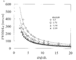
- FIG. 4 is a diagram re-plotting the relationship between FWHM and coupling efficiency described in FIG. 3 with d ⁇ /d ⁇ on the horizontal axis.
- data with different optical fiber structures ( ⁇ , a) and center wavelengths ( ⁇ 0 ) are superimposed. It can be seen from FIG. 4 that the relationship between FWHM and d ⁇ /d ⁇ is uniquely determined with respect to the coupling efficiency regardless of the fiber structure and center wavelength.
- FIG. 5 is a diagram for explaining the relationship between the product of FWHM and Lc and d ⁇ /d ⁇ .
- Each plot shows the relationship between the product of FWHM and Lc obtained by calculation and d ⁇ /d ⁇ , and the dashed line indicates the approximate function obtained for each coupling efficiency.
- Equations (3) to (6) show approximate functions for each coupling efficiency.
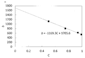
- FIG. 6 shows the relationship between the coupling efficiency and the inversely proportional coefficient b. From FIG. 6, the coefficient b is obtained from the formula (8). where C is the coupling efficiency in linear representation.
- the mode conversion device according to the present invention has a long-period grating in the core of an optical fiber capable of propagating light in at least two propagation modes, and the long-period grating satisfies the relationship of number C1. do.
- Full width half maximum FWHM is the wavelength band where the coupling efficiency is half compared to the coupling efficiency of mode conversion at the center wavelength
- C is the coupling efficiency
- Lc is the complete coupling length
- Lg is the grating length
- ⁇ is the grating pitch
- ⁇ It is the propagation constant difference between the two propagation modes at the center wavelength to be mode-converted.
- the conversion efficiency of the LP01 mode and the LP11 mode was used as an example for the calculation, but the coupling between other modes such as the LP01 mode and the cladding mode, the LP01 mode and the LP02 mode, the LP11 mode and the LP21 mode, etc. can be thought of as Moreover, regardless of whether the optical fiber has a step index structure, other structures such as a graded index structure can be similarly considered.
- FIG. 7 is a flow chart illustrating a method of designing a long-period grating for the mode conversion device described in Embodiment 1.
- the design method is a design method for determining design parameters of a long-period grating installed in the core of an optical fiber capable of propagating light in at least two propagation modes,
- the core radius a ( ⁇ m) of the optical fiber, the relative refractive index difference ⁇ (%), the center wavelength ⁇ 0 (nm) of the light that performs mode conversion, the coupling efficiency C, and the full width at half maximum FWHM (nm) are given (step S01)
- From the core radius a ( ⁇ m) and the relative refractive index difference ⁇ (%) of the optical fiber From the core radius a ( ⁇ m) and the relative refractive index difference ⁇ (%) of the optical fiber, the propagation constant difference ⁇ of the two propagation modes at the center wavelength ⁇ 0 (nm) to be mode-converted and its wavelength derivative d ⁇ /
- the design parameters are d ⁇ /d ⁇ , Lc, Lg, ⁇ , ⁇ 0 , C and FWHM, which describe the optical fiber structure.
- the core radius a ( ⁇ m) of the optical fiber, the relative refractive index difference ⁇ (%), the center wavelength ⁇ 0 (nm) of the light for mode conversion, the coupling efficiency C, and the full width at half maximum FWHM (nm) are given.
- step S02 the propagation constant difference ⁇ at the center wavelength ⁇ 0 (nm) and its wavelength derivative d ⁇ /d ⁇ are obtained by modal analysis from the core radius a ( ⁇ m) and the relative refractive index difference ⁇ (%) of the optical fiber structure.
- step S03 the propagation constant difference ⁇ is substituted into equation (C2) to calculate the grating pitch ⁇ ( ⁇ m).
- step S04 the coupling efficiency C, which is the specification value, is substituted into the equation (C3) to calculate the coefficient b.
- step S05 the coefficient b, the full width at half maximum FWHM of the specification value, and the wavelength derivative d ⁇ /d ⁇ are substituted into the equation (C4) to calculate the complete coupling length Lc.
- step S06 the grating length Lg is calculated by substituting the complete coupling length Lc and the coupling efficiency C, which is the specification value, into the equation C5.
- step S03 and steps (S04 to S06) may be performed at the same time, or one of them may be performed first.
- the mode-convertible wavelength range varies depending on the device using LPG. For example, when using a wide band for mode-multiplexed transmission or the like, a wider band is desirable. On the other hand, in the case of a tap device as described in Embodiment 3, narrower is desirable.
- the point of the design method of this embodiment is that the grating pitch ⁇ and the grating length Lg can be derived according to the application (specification) of the device.
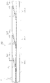
- FIG. 8 is a diagram illustrating the mode conversion device 301 of this embodiment.
- the mode conversion device 301 is located downstream of the long-period grating 21 in the light propagation direction. It is characterized by further comprising a tap waveguide 53 for outputting the light of the wavelength from the side surface of the optical fiber.
- the mode conversion device 301 includes a tap section 10 formed with a tap waveguide 53 for outputting, from the side surface of the optical fiber 50, high-order mode light among the light propagating through the core 51 of the optical fiber 50; a grating unit 20 located in front of the tap unit 10 in the light propagation direction and having a grating 21 formed in a core 51 of an optical fiber 50 for converting light of a desired wavelength from the fundamental mode to the higher-order mode; Prepare.
- the optical fiber 50 is a step-index fiber.
- the optical fiber 50 has the grating section 20 and the tap section 10 formed in order in the longitudinal direction.
- a direction in which light can enter the tap waveguide 53 is defined as an optical waveguide direction. In FIG. 8, the light guiding direction is from left to right. Also, the direction in which the tap waveguide 53 faces from the core 51 to the side surface of the optical fiber 50 is the tap direction. In FIG. 8, the tap direction is a direction tilted forward with respect to the optical waveguide direction.
- the grating section 20 converts a desired amount of light of a wavelength desired to be extracted from the light propagating through the core 51 of the optical fiber 50 from the LP01 mode to the LP11 mode by the long-period grating 21 .
- the grating structure can be realized, for example, by femtosecond laser machining, CO2 laser machining, or pressing of the grating.
- the tap section 10 has a tap waveguide 53 extending from the center of the core 51 toward the side surface of the optical fiber 50 (the interface of the clad 52) at an angle ⁇ .
- the tap section 10 selectively extracts only the LP11 mode from the core 51. Take out.
- tap light light coupled from the core 51 to the tap waveguide 53
- transmitted light light propagating through the core 51 as it is.
- the light receiver 54 by connecting the light receiver 54 to the output end of the tap section 10 (the side surface of the optical fiber 50), only the tap light can be extracted from the optical fiber 50 and received.
- the coupling efficiency from the core 51 to the tap waveguide 53 strongly depends on the propagation mode of light propagating through the core 51 . This is because the higher the order mode, the smaller the confinement and the easier the coupling to the tap waveguide 53 . Therefore, only higher-order modes can be transferred to the tap waveguide.
- the values of the refractive index and the diameter dt of the tap waveguide 53 are important. If these values are too large, the NA of the tap waveguide 53 will increase, and the LP01 mode will also be easily coupled, resulting in increased loss of transmitted light. On the other hand, if these values are too small, the NA of the tap waveguide 53 will become small, making it difficult to couple higher-order modes, and the coupling efficiency of the tap light to the tap waveguide 53 will decrease. In other words, it is necessary to appropriately determine the values of the refractive index and diameter dt of the tap waveguide 53 .
- ⁇ is made sufficiently small and the mode is adiabatically transitioned.
- ⁇ is large, the LP01 mode is also affected by the tap waveguide 51 and coupled with the radiation mode, resulting in loss. Therefore, the upper limit of ⁇ is determined from the viewpoint of the LP01 mode loss.
- ⁇ can take any value greater than 0, but since ⁇ determines the total length L tap of the tap section 10, ⁇ is determined.
- the diameter df of the optical fiber 50 is 125 ⁇ m.
- ⁇ In order to set the tap portion L tap to 5 cm or less, ⁇ must be set to 0.07° or more.
- the grating section 20 has a grating 21 with a pitch ⁇ .
- grating 21 is a long period fiber grating (LPG).
- LPG long period fiber grating
- the grating 21 is molded with the design parameters described in the first and second embodiments.
- Mode conversion device 302 is characterized in that a set of long-period grating 21 and tap waveguide 53 of mode conversion device 301 described in FIG. That is, the mode conversion device 302 is a system in which the mode conversion devices 301 are combined in multiple stages.
- a set of the long-period grating 21 and the tap waveguide 53 (mode conversion device 301) is arranged, for example, at a certain distance (several meters to several kilometers).
- the long-period gratings 21 of the mode conversion device 302 of FIG. 9 are characterized in that the design parameters described in the equation C1 are different such that the wavelengths of light converted from the one mode to the other mode are different. do.
- the mode conversion device 302 in FIG. 9 allocates a wavelength to each mode conversion device (301-1, 301-2, 301-3) and controls the signal to be extracted according to the wavelength. Signals can be extracted at arbitrary wavelength intervals by setting the design parameters of each mode conversion device according to the wavelength intervals (center wavelength ⁇ 0 and bandwidth (FWHM)) of wavelengths to be extracted.
- the long-period gratings 21 of the mode conversion device 302 of FIG. 10 are characterized by having different grating lengths Lg so that the wavelengths of light converted from the one mode to the other mode are the same and the coupling efficiencies are different. do.
- Mode conversion device 302 in FIG. 10 allocates a plurality of mode conversion devices (301-1, 301-2, 301-3) to one wavelength. By sending a signal with one wavelength and controlling the coupling efficiency of each LPG, the signal can be extracted little by little in multiple stages.
- the mode conversion device 302 of FIG. 10 can simultaneously output signals from a plurality of locations with one wavelength.
Landscapes
- Physics & Mathematics (AREA)
- General Physics & Mathematics (AREA)
- Optics & Photonics (AREA)
- Optical Integrated Circuits (AREA)
Abstract
Priority Applications (5)
| Application Number | Priority Date | Filing Date | Title |
|---|---|---|---|
| EP21926486.8A EP4296732A1 (fr) | 2021-02-17 | 2021-02-17 | Dispositif de conversion de mode et procédé de conception |
| JP2023500172A JPWO2022176046A1 (fr) | 2021-02-17 | 2021-02-17 | |
| CN202180089866.2A CN116724257A (zh) | 2021-02-17 | 2021-02-17 | 模式转换设备以及设计方法 |
| US18/277,320 US20240142696A1 (en) | 2021-02-17 | 2021-02-17 | Mode conversion device and design method |
| PCT/JP2021/005851 WO2022176046A1 (fr) | 2021-02-17 | 2021-02-17 | Dispositif de conversion de mode et procédé de conception |
Applications Claiming Priority (1)
| Application Number | Priority Date | Filing Date | Title |
|---|---|---|---|
| PCT/JP2021/005851 WO2022176046A1 (fr) | 2021-02-17 | 2021-02-17 | Dispositif de conversion de mode et procédé de conception |
Publications (1)
| Publication Number | Publication Date |
|---|---|
| WO2022176046A1 true WO2022176046A1 (fr) | 2022-08-25 |
Family
ID=82930304
Family Applications (1)
| Application Number | Title | Priority Date | Filing Date |
|---|---|---|---|
| PCT/JP2021/005851 WO2022176046A1 (fr) | 2021-02-17 | 2021-02-17 | Dispositif de conversion de mode et procédé de conception |
Country Status (5)
| Country | Link |
|---|---|
| US (1) | US20240142696A1 (fr) |
| EP (1) | EP4296732A1 (fr) |
| JP (1) | JPWO2022176046A1 (fr) |
| CN (1) | CN116724257A (fr) |
| WO (1) | WO2022176046A1 (fr) |
Citations (3)
| Publication number | Priority date | Publication date | Assignee | Title |
|---|---|---|---|---|
| JPS62229110A (ja) * | 1986-01-17 | 1987-10-07 | ザ・ボ−ド・オブ・トラステイ−ズ・オブ・ザ・レランド・スタンフオ−ド・ジユニア・ユニバ−シテイ | 光フアイバモ−ドセレクタおよびその製作方法 |
| US5216739A (en) * | 1991-02-19 | 1993-06-01 | Her Majesty The Queen In Right Of Canada, As Represented By The Minister Of Communications | Method of creating an index grating in an optical fiber and a mode converter using the index grating |
| JP2017156641A (ja) * | 2016-03-03 | 2017-09-07 | 日本電信電話株式会社 | 光ファイバ、モード変換器、光増幅器及び光伝送システム |
-
2021
- 2021-02-17 CN CN202180089866.2A patent/CN116724257A/zh active Pending
- 2021-02-17 JP JP2023500172A patent/JPWO2022176046A1/ja active Pending
- 2021-02-17 EP EP21926486.8A patent/EP4296732A1/fr active Pending
- 2021-02-17 WO PCT/JP2021/005851 patent/WO2022176046A1/fr active Application Filing
- 2021-02-17 US US18/277,320 patent/US20240142696A1/en active Pending
Patent Citations (3)
| Publication number | Priority date | Publication date | Assignee | Title |
|---|---|---|---|---|
| JPS62229110A (ja) * | 1986-01-17 | 1987-10-07 | ザ・ボ−ド・オブ・トラステイ−ズ・オブ・ザ・レランド・スタンフオ−ド・ジユニア・ユニバ−シテイ | 光フアイバモ−ドセレクタおよびその製作方法 |
| US5216739A (en) * | 1991-02-19 | 1993-06-01 | Her Majesty The Queen In Right Of Canada, As Represented By The Minister Of Communications | Method of creating an index grating in an optical fiber and a mode converter using the index grating |
| JP2017156641A (ja) * | 2016-03-03 | 2017-09-07 | 日本電信電話株式会社 | 光ファイバ、モード変換器、光増幅器及び光伝送システム |
Non-Patent Citations (2)
| Title |
|---|
| CRAIG D. POOLE: "Helical-Grating Two-Mode Fiber Spatial-Mode Coupler", JOURNAL OF LIGHTWAVE TECHNOLOGY, vol. 9, no. 5, May 1991 (1991-05-01), XP000206687, DOI: 10.1109/50.79536 |
| FANG JIAN, LI AN, SHIEH WILLIAM: "Low-DMD few-mode fiber with distributed long-period grating", OPTICS LETTERS, OPTICAL SOCIETY OF AMERICA, US, vol. 40, no. 17, 1 September 2015 (2015-09-01), US , pages 3937 - 3940, XP055965133, ISSN: 0146-9592, DOI: 10.1364/OL.40.003937 * |
Also Published As
| Publication number | Publication date |
|---|---|
| US20240142696A1 (en) | 2024-05-02 |
| CN116724257A (zh) | 2023-09-08 |
| EP4296732A1 (fr) | 2023-12-27 |
| JPWO2022176046A1 (fr) | 2022-08-25 |
Similar Documents
| Publication | Publication Date | Title |
|---|---|---|
| KR101233597B1 (ko) | 모드 변환기 | |
| US11131809B2 (en) | Integrated polarization splitter | |
| JP5059797B2 (ja) | 光ファイバ、光ファイバの設計方法及び光波長多重通信システム | |
| CN104483735B (zh) | 一种全光纤模式转换器的光系统 | |
| US7630643B2 (en) | Multimode optical transmission system and multimode optical transmission method | |
| JP4636439B2 (ja) | 方向性光結合器の2つの直線光導波路のコア幅及びコア間の距離の計算方法 | |
| CN110741293B (zh) | 光纤和光传输系统 | |
| EP1229363A2 (fr) | Structure de couplage optique | |
| WO2022059205A1 (fr) | Circuit d'entrée/sortie côté optique et connecteur optique | |
| JP6824814B2 (ja) | 損失差補償器 | |
| WO2022176046A1 (fr) | Dispositif de conversion de mode et procédé de conception | |
| Ye et al. | Wavelength-dependent crosstalk in trench-assisted multi-core fibers | |
| US8295661B2 (en) | Flat-top response arrayed waveguide grating | |
| JP5843366B2 (ja) | 光ファイバ | |
| US7095924B2 (en) | Optical filter | |
| KR100585016B1 (ko) | 고차 모드 제거 필터링 기능을 갖는 단일모드 광섬유 구조 | |
| JP2000171663A (ja) | クラッドモ―ド結合器とブラッグファイバ格子で形成されるアッド/ドロップフィルタ―及びマルチプレクサ | |
| WO2016170890A1 (fr) | Coupleur à réseau | |
| JP5875049B2 (ja) | マルチモード光ファイバ及びマルチモード光ファイバ設計方法 | |
| JP6697365B2 (ja) | モード合分波光回路 | |
| JP7480853B2 (ja) | モード変換器及び光伝送システム | |
| EP1421422A1 (fr) | Reseau a guides d'ondes en faisceau a dispersion chromatique reduite | |
| JP7061771B2 (ja) | モード交換器 | |
| JP7491387B2 (ja) | 光側方入出力回路及び光コネクタ | |
| WO2023275921A1 (fr) | Circuit d'entrée/sortie de lumière latérale |
Legal Events
| Date | Code | Title | Description |
|---|---|---|---|
| 121 | Ep: the epo has been informed by wipo that ep was designated in this application |
Ref document number: 21926486 Country of ref document: EP Kind code of ref document: A1 |
|
| ENP | Entry into the national phase |
Ref document number: 2023500172 Country of ref document: JP Kind code of ref document: A |
|
| WWE | Wipo information: entry into national phase |
Ref document number: 202180089866.2 Country of ref document: CN |
|
| WWE | Wipo information: entry into national phase |
Ref document number: 18277320 Country of ref document: US |
|
| WWE | Wipo information: entry into national phase |
Ref document number: 2021926486 Country of ref document: EP |
|
| NENP | Non-entry into the national phase |
Ref country code: DE |
|
| ENP | Entry into the national phase |
Ref document number: 2021926486 Country of ref document: EP Effective date: 20230918 |