WO2022172910A1 - 偏波保持光ファイバ及び偏波保持光ファイバの製造方法 - Google Patents
偏波保持光ファイバ及び偏波保持光ファイバの製造方法 Download PDFInfo
- Publication number
- WO2022172910A1 WO2022172910A1 PCT/JP2022/004871 JP2022004871W WO2022172910A1 WO 2022172910 A1 WO2022172910 A1 WO 2022172910A1 JP 2022004871 W JP2022004871 W JP 2022004871W WO 2022172910 A1 WO2022172910 A1 WO 2022172910A1
- Authority
- WO
- WIPO (PCT)
- Prior art keywords
- polarization
- maintaining
- optical fiber
- refractive index
- core
- Prior art date
- Legal status (The legal status is an assumption and is not a legal conclusion. Google has not performed a legal analysis and makes no representation as to the accuracy of the status listed.)
- Ceased
Links
Images









Classifications
-
- G—PHYSICS
- G02—OPTICS
- G02B—OPTICAL ELEMENTS, SYSTEMS OR APPARATUS
- G02B6/00—Light guides; Structural details of arrangements comprising light guides and other optical elements, e.g. couplings
- G02B6/02—Optical fibres with cladding with or without a coating
- G02B6/024—Optical fibres with cladding with or without a coating with polarisation maintaining properties
-
- C—CHEMISTRY; METALLURGY
- C03—GLASS; MINERAL OR SLAG WOOL
- C03B—MANUFACTURE, SHAPING, OR SUPPLEMENTARY PROCESSES
- C03B37/00—Manufacture or treatment of flakes, fibres, or filaments from softened glass, minerals, or slags
- C03B37/01—Manufacture of glass fibres or filaments
- C03B37/012—Manufacture of preforms for drawing fibres or filaments
- C03B37/01205—Manufacture of preforms for drawing fibres or filaments starting from tubes, rods, fibres or filaments
- C03B37/01211—Manufacture of preforms for drawing fibres or filaments starting from tubes, rods, fibres or filaments by inserting one or more rods or tubes into a tube
- C03B37/01217—Manufacture of preforms for drawing fibres or filaments starting from tubes, rods, fibres or filaments by inserting one or more rods or tubes into a tube for making preforms of polarisation-maintaining optical fibres
-
- C—CHEMISTRY; METALLURGY
- C03—GLASS; MINERAL OR SLAG WOOL
- C03B—MANUFACTURE, SHAPING, OR SUPPLEMENTARY PROCESSES
- C03B37/00—Manufacture or treatment of flakes, fibres, or filaments from softened glass, minerals, or slags
- C03B37/01—Manufacture of glass fibres or filaments
- C03B37/02—Manufacture of glass fibres or filaments by drawing or extruding, e.g. direct drawing of molten glass from nozzles; Cooling fins therefor
- C03B37/025—Manufacture of glass fibres or filaments by drawing or extruding, e.g. direct drawing of molten glass from nozzles; Cooling fins therefor from reheated softened tubes, rods, fibres or filaments, e.g. drawing fibres from preforms
- C03B37/027—Fibres composed of different sorts of glass, e.g. glass optical fibres
- C03B37/02709—Polarisation maintaining fibres, e.g. PM, PANDA, bi-refringent optical fibres
-
- G—PHYSICS
- G02—OPTICS
- G02B—OPTICAL ELEMENTS, SYSTEMS OR APPARATUS
- G02B6/00—Light guides; Structural details of arrangements comprising light guides and other optical elements, e.g. couplings
- G02B6/02—Optical fibres with cladding with or without a coating
- G02B6/02042—Multicore optical fibres
-
- G—PHYSICS
- G02—OPTICS
- G02B—OPTICAL ELEMENTS, SYSTEMS OR APPARATUS
- G02B6/00—Light guides; Structural details of arrangements comprising light guides and other optical elements, e.g. couplings
- G02B6/02—Optical fibres with cladding with or without a coating
- G02B6/036—Optical fibres with cladding with or without a coating core or cladding comprising multiple layers
-
- C—CHEMISTRY; METALLURGY
- C03—GLASS; MINERAL OR SLAG WOOL
- C03B—MANUFACTURE, SHAPING, OR SUPPLEMENTARY PROCESSES
- C03B2201/00—Type of glass produced
- C03B2201/06—Doped silica-based glasses
- C03B2201/08—Doped silica-based glasses doped with boron or fluorine or other refractive index decreasing dopant
- C03B2201/10—Doped silica-based glasses doped with boron or fluorine or other refractive index decreasing dopant doped with boron
-
- C—CHEMISTRY; METALLURGY
- C03—GLASS; MINERAL OR SLAG WOOL
- C03B—MANUFACTURE, SHAPING, OR SUPPLEMENTARY PROCESSES
- C03B2201/00—Type of glass produced
- C03B2201/06—Doped silica-based glasses
- C03B2201/08—Doped silica-based glasses doped with boron or fluorine or other refractive index decreasing dopant
- C03B2201/12—Doped silica-based glasses doped with boron or fluorine or other refractive index decreasing dopant doped with fluorine
-
- C—CHEMISTRY; METALLURGY
- C03—GLASS; MINERAL OR SLAG WOOL
- C03B—MANUFACTURE, SHAPING, OR SUPPLEMENTARY PROCESSES
- C03B2201/00—Type of glass produced
- C03B2201/06—Doped silica-based glasses
- C03B2201/20—Doped silica-based glasses doped with non-metals other than boron or fluorine
-
- C—CHEMISTRY; METALLURGY
- C03—GLASS; MINERAL OR SLAG WOOL
- C03B—MANUFACTURE, SHAPING, OR SUPPLEMENTARY PROCESSES
- C03B2201/00—Type of glass produced
- C03B2201/06—Doped silica-based glasses
- C03B2201/30—Doped silica-based glasses doped with metals, e.g. Ga, Sn, Sb, Pb or Bi
- C03B2201/31—Doped silica-based glasses doped with metals, e.g. Ga, Sn, Sb, Pb or Bi doped with germanium
-
- C—CHEMISTRY; METALLURGY
- C03—GLASS; MINERAL OR SLAG WOOL
- C03B—MANUFACTURE, SHAPING, OR SUPPLEMENTARY PROCESSES
- C03B2203/00—Fibre product details, e.g. structure, shape
- C03B2203/10—Internal structure or shape details
- C03B2203/22—Radial profile of refractive index, composition or softening point
-
- C—CHEMISTRY; METALLURGY
- C03—GLASS; MINERAL OR SLAG WOOL
- C03B—MANUFACTURE, SHAPING, OR SUPPLEMENTARY PROCESSES
- C03B2203/00—Fibre product details, e.g. structure, shape
- C03B2203/10—Internal structure or shape details
- C03B2203/22—Radial profile of refractive index, composition or softening point
- C03B2203/23—Double or multiple optical cladding profiles
-
- C—CHEMISTRY; METALLURGY
- C03—GLASS; MINERAL OR SLAG WOOL
- C03B—MANUFACTURE, SHAPING, OR SUPPLEMENTARY PROCESSES
- C03B2203/00—Fibre product details, e.g. structure, shape
- C03B2203/30—Polarisation maintaining [PM], i.e. birefringent products, e.g. with elliptical core, by use of stress rods, "PANDA" type fibres
-
- C—CHEMISTRY; METALLURGY
- C03—GLASS; MINERAL OR SLAG WOOL
- C03B—MANUFACTURE, SHAPING, OR SUPPLEMENTARY PROCESSES
- C03B2203/00—Fibre product details, e.g. structure, shape
- C03B2203/30—Polarisation maintaining [PM], i.e. birefringent products, e.g. with elliptical core, by use of stress rods, "PANDA" type fibres
- C03B2203/31—Polarisation maintaining [PM], i.e. birefringent products, e.g. with elliptical core, by use of stress rods, "PANDA" type fibres by use of stress-imparting rods, e.g. by insertion
-
- C—CHEMISTRY; METALLURGY
- C03—GLASS; MINERAL OR SLAG WOOL
- C03B—MANUFACTURE, SHAPING, OR SUPPLEMENTARY PROCESSES
- C03B2203/00—Fibre product details, e.g. structure, shape
- C03B2203/34—Plural core other than bundles, e.g. double core
-
- C—CHEMISTRY; METALLURGY
- C03—GLASS; MINERAL OR SLAG WOOL
- C03B—MANUFACTURE, SHAPING, OR SUPPLEMENTARY PROCESSES
- C03B37/00—Manufacture or treatment of flakes, fibres, or filaments from softened glass, minerals, or slags
- C03B37/01—Manufacture of glass fibres or filaments
- C03B37/012—Manufacture of preforms for drawing fibres or filaments
- C03B37/01205—Manufacture of preforms for drawing fibres or filaments starting from tubes, rods, fibres or filaments
- C03B37/01225—Means for changing or stabilising the shape, e.g. diameter, of tubes or rods in general, e.g. collapsing
- C03B37/01228—Removal of preform material
- C03B37/01231—Removal of preform material to form a longitudinal hole, e.g. by drilling
-
- C—CHEMISTRY; METALLURGY
- C03—GLASS; MINERAL OR SLAG WOOL
- C03B—MANUFACTURE, SHAPING, OR SUPPLEMENTARY PROCESSES
- C03B37/00—Manufacture or treatment of flakes, fibres, or filaments from softened glass, minerals, or slags
- C03B37/01—Manufacture of glass fibres or filaments
- C03B37/012—Manufacture of preforms for drawing fibres or filaments
- C03B37/0128—Manufacture of preforms for drawing fibres or filaments starting from pulverulent glass
- C03B37/01282—Manufacture of preforms for drawing fibres or filaments starting from pulverulent glass by pressing or sintering, e.g. hot-pressing
-
- C—CHEMISTRY; METALLURGY
- C03—GLASS; MINERAL OR SLAG WOOL
- C03B—MANUFACTURE, SHAPING, OR SUPPLEMENTARY PROCESSES
- C03B37/00—Manufacture or treatment of flakes, fibres, or filaments from softened glass, minerals, or slags
- C03B37/01—Manufacture of glass fibres or filaments
- C03B37/012—Manufacture of preforms for drawing fibres or filaments
- C03B37/014—Manufacture of preforms for drawing fibres or filaments made entirely or partially by chemical means, e.g. vapour phase deposition of bulk porous glass either by outside vapour deposition [OVD], or by outside vapour phase oxidation [OVPO] or by vapour axial deposition [VAD]
Definitions
- the present disclosure relates to a polarization-maintaining optical fiber and a method for manufacturing a polarization-maintaining optical fiber.
- a polarization-maintaining optical fiber in which stress applying parts (SAP) made of a material different from that of the clad are provided inside the clad. SAP can induce stress-induced birefringence.
- Polarization-maintaining optical fibers with non-circular cores are also known. With a non-circular core, the effective refractive index can be changed depending on the direction of polarization due to the asymmetry of the refractive index distribution shape in the fiber cross section.
- Non-Patent Document 1 discloses various types of polarization-maintaining optical fibers and representative manufacturing methods.
- a polarization-maintaining optical fiber of the present disclosure comprises at least one or more polarization-maintaining cores, an optical cladding surrounding the at least one or more polarization-maintaining cores, and a common physical cladding surrounding the optical claddings.
- the at least one polarization maintaining core has a core made of glass and a pair of low refractive index portions having a lower refractive index than the core.
- the refractive index of the optical cladding is lower than the refractive index of the core.
- the refractive index of the common physical cladding is lower than the refractive index of the core.
- the cross section orthogonal to the longitudinal direction of the polarization-maintaining optical fiber at least a part of the outer periphery of each of the pair of low refractive index portions is in contact with the core, and the core is excluding the portions in contact with the low refractive index portions. is circular.
- the maximum absolute value of the residual stress in the cross section is 100 MPa or less, or the difference in coefficient of thermal expansion between the glass portions of the polarization-maintaining optical fiber is 5 ⁇ 10 ⁇ 7 /K or less. or the glass of each portion constituting the polarization-maintaining optical fiber is silica glass having a B 2 O 3 concentration of 1% or less or 0% by mass fraction.
- the X-axis is parallel to the straight line connecting the centers of the pair of low refractive index portions and passes through the origin that is the center of each of the at least one or more polarization-maintaining cores
- the Y-axis is the X.
- I(X, Y) be the near-field intensity distribution described in the local coordinate system in each of the at least one or more polarization-maintaining cores, which is an axis perpendicular to the axis and passing through the origin, and is defined by the following equation. is 0.05 or more and 0.40 or less at any wavelength in the range of 850 nm or more and 1625 nm or less.
- the manufacturing method of the polarization-maintaining optical fiber of the present disclosure includes at least one polarization-maintaining core having a core made of glass and a pair of low refractive index portions having a refractive index lower than that of the core. an optical cladding surrounding the at least one polarization-maintaining core; and a common physical cladding surrounding the optical cladding.
- a method for manufacturing a polarization-maintaining optical fiber includes preparing an optical preform made of glass and having cylindrical symmetry and including a core portion and an optical cladding portion; preparing a low refractive index portion base material having a thermal expansion coefficient that is 5 ⁇ 10 -7 /K or less different from the thermal expansion coefficient of the optical base material in a cross section perpendicular to the central axis of the optical base material Forming a pair of cylindrical holes in the optical base material which are point-symmetrical with respect to the central axis of the material and have central axes parallel to the central axis of the optical base material; forming at least one or more polarization-maintaining optical preforms corresponding to the at least one or more polarization-maintaining cores by inserting them one by one into the holes of the optical preform and integrating them by heating; spinning by drawing after or while adding a common physical cladding around one or more polarization-maintaining optical preforms.
- the manufacturing method of the polarization-maintaining optical fiber of the present disclosure includes at least one polarization-maintaining core having a core made of glass and a pair of low refractive index portions having a refractive index lower than that of the core. an optical cladding surrounding the at least one polarization-maintaining core; and a common physical cladding surrounding the optical cladding.
- a method for manufacturing a polarization-maintaining optical fiber comprises: a core portion which is made of glass and has cylindrical symmetry; and a core portion which surrounds the core portion and which is cylindrically symmetric and made of glass.
- An optical cladding portion having a thermal expansion coefficient of ⁇ 10 ⁇ 7 /K or less; surrounding the optical cladding portion, made of glass, having an outer periphery with translational symmetry along a predetermined axis; a common physical cladding portion having a thermal expansion coefficient different from the expansion coefficient by 5 ⁇ 10 ⁇ 7 /K or less; and a cross section perpendicular to the central axis of the core portion.
- each hole being the core portion and the optical cladding It is formed in the basic optical fiber preform so as to be formed over the portion, and is made of glass, and has a difference from the thermal expansion coefficient of the core portion and a difference from the thermal expansion coefficient of the common physical cladding portion, respectively.
- a low refractive index portion base material having a thermal expansion coefficient of 5 ⁇ 10 ⁇ 7 /K or less, being cylindrically symmetric, and having an outer diameter adjusted to be insertable into the hole; inserting the low refractive index portion preforms one by one into the holes of the basic optical fiber preform and integrating them, and then drawing and spinning them while they are being integrated.
- FIG. 1 is a cross-sectional view of a polarization-maintaining optical fiber according to a first comparative example.
- FIG. 2 is a cross-sectional view of a polarization-maintaining optical fiber according to a second comparative example.
- FIG. 3 is a cross-sectional view of a polarization-maintaining optical fiber according to a third comparative example.
- FIG. 4 is a cross-sectional view of a polarization-maintaining optical fiber according to a fourth comparative example.
- FIG. 5 is a graph showing the relationship between polarization crosstalk and polarization mode loss.
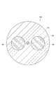
- FIG. 6 is a cross-sectional view of a polarization-maintaining optical fiber according to an embodiment.
- FIG. 1 is a cross-sectional view of a polarization-maintaining optical fiber according to a first comparative example.
- FIG. 2 is a cross-sectional view of a polarization
- FIG. 7 is a partially enlarged cross-sectional view of the polarization maintaining optical fiber shown in FIG.
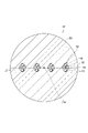
- FIG. 8 is a cross-sectional view of a polarization-maintaining optical fiber according to a first modified example.
- FIG. 9 is a cross-sectional view of a polarization-maintaining optical fiber according to a second modification.
- FIG. 10 is a cross-sectional view of a polarization-maintaining optical fiber according to a third modified example.
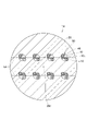
- FIG. 11 is a cross-sectional view of a polarization-maintaining optical fiber according to a fourth modification.
- FIG. 12 is a cross-sectional view of a polarization-maintaining optical fiber according to a fifth modification.
- FIG. 13 is a cross-sectional view of a polarization-maintaining optical fiber according to a sixth modification.
- FIG. 14 is a cross-sectional view of a polarization-maintaining optical fiber according to a seventh modification.
- FIG. 15 is a cross-sectional view of a polarization-maintaining optical fiber according to an eighth modification.
- FIG. 16 is a cross-sectional view of a polarization-maintaining optical fiber according to a ninth modification.
- FIG. 17 is a cross-sectional view of a polarization-maintaining optical fiber according to a tenth modification.
- FIG. 18 is a flow chart showing the manufacturing method according to the first embodiment.
- FIG. 19 is a flow chart showing a manufacturing method according to a modification of the first embodiment.
- FIG. 20 is a flow chart showing a manufacturing method according to the second embodiment.
- FIG. 21 is a flow chart showing a manufacturing method according to a
- a polarization-maintaining optical fiber with a non-circular core has a high connection loss when connected to a normal standard optical fiber such as a general-purpose single-mode fiber.
- connection loss with ordinary optical fibers in other words, the coupling loss when inputting and outputting a light beam that can be approximated as having a circularly symmetrical Gaussian intensity distribution on a cross section perpendicular to the traveling direction) (Gaussian beam coupling loss)) and has polarization-maintaining performance sufficient to suppress polarization mode loss caused by polarization crosstalk during propagation over short distances and a method for manufacturing a polarization-maintaining optical fiber.
- a polarization-maintaining optical fiber includes at least one or more polarization-maintaining cores, an optical cladding surrounding the at least one or more polarization-maintaining cores, and a common physical cladding surrounding the optical claddings. , prepare.
- the at least one polarization maintaining core has a core made of glass and a pair of low refractive index portions having a lower refractive index than the core.
- the refractive index of the optical cladding is lower than the refractive index of the core.
- the refractive index of the common physical cladding is lower than the refractive index of the core.
- the cross section orthogonal to the longitudinal direction of the polarization-maintaining optical fiber at least a part of the outer periphery of each of the pair of low refractive index portions is in contact with the core, and the core is excluding the portions in contact with the low refractive index portions. is circular.
- the maximum absolute value of the residual stress in the cross section is 100 MPa or less, or the difference in coefficient of thermal expansion between the glass portions of the polarization-maintaining optical fiber is 5 ⁇ 10 ⁇ 7 /K or less.
- the X-axis is parallel to the straight line connecting the centers of the pair of low refractive index portions and passes through the origin that is the center of each of the at least one or more polarization-maintaining cores
- the Y-axis is the X.
- I(X, Y) be the near-field intensity distribution described in the local coordinate system in each of the at least one or more polarization-maintaining cores, which is an axis perpendicular to the axis and passing through the origin, and is defined by the following equation. is 0.05 or more and 0.40 or less at any wavelength in the range of 850 nm or more and 1625 nm or less.
- birefringence is the center of gravity of I(X, Y)
- D4 ⁇ X is the D4 ⁇ beam width in the X-axis direction
- D4 ⁇ Y is the D4 ⁇ beam width in the Y-axis direction.
- the magnitude of birefringence can be measured, for example, by the method described in JIS C6872:2008 "Polarization Preserving Optical Fiber Beat Length Test Method". In order to achieve a birefringence of 1 ⁇ 10 ⁇ 5 or more, f ⁇ 0.05 is required.
- f ⁇ 0.40 is required, and in order to be 0.2 dB or less, f ⁇ 0.30 is required, which is 0.1 dB or less. requires f ⁇ 0.25.
- the above polarization-maintaining optical fiber can suppress connection loss when connected to a normal optical fiber. Since no SAP is required inside the core and clad, damage or bursting of the optical fiber preform due to differences in thermal expansion coefficients is suppressed. Therefore, it is easy to manufacture. It has sufficient polarization maintaining performance at short distances.
- the first condition is that the outer peripheries of the pair of low refractive index portions are circular
- the second condition is that the pair of low refractive index portions is , the at least one or more polarization-maintaining cores are arranged point-symmetrically with respect to the central axis of each
- a third condition is that the refractive index distribution of each of the at least one or more polarization-maintaining cores is Except for the low refractive index portion, the at least one polarization-maintaining core is axially symmetrical with respect to the central axis of each
- the fourth condition is that each of the pair of low refractive index portions has at least one The outer circumference not in contact with the polarization-maintaining core is in contact with the optical clad
- the fifth condition is that each of the pair of low-refractive-index portions is made of glass, and constitutes the polarization-main
- the difference between the thermal expansion coefficient of the glass of the low refractive index portion and the thermal expansion coefficient of the glass of the other portion is 5 ⁇ 10 ⁇ 7 /K or less, or B 2 in the glass of the low refractive index portion
- the concentration of O 3 is 1% or less or 0% in terms of mass fraction, and any one or more of the first to fifth conditions may be satisfied.
- a hole parallel to the central axis is made in the optical fiber preform, a low refractive index rod is inserted into the hole, and the optical fiber preform and the low refractive index rod are heated and integrated to form the light beam. It becomes easy to form the low refractive index portion in the fiber preform, and excellent polarization maintaining performance can be realized when an optical fiber is formed.
- the polarization maintaining core may be a plurality of polarization maintaining cores. In this case, a plurality of polarization-maintaining lights can be propagated.
- the plurality of polarization-maintaining cores may be arranged so as to have two-fold or more rotational symmetry with respect to the central axis of the common physical cladding in the cross section. In this case, it can be easily optically coupled with a grating coupler arranged to have two-fold or more rotational symmetry.
- the plurality of polarization-maintaining cores each have a polarization-maintaining direction in the cross section that is perpendicular to a straight line connecting the central axes of the pair of low refractive index portions and passes through the central axis of each of the plurality of polarization-maintaining cores.
- and may be arranged to have two-fold or more rotational symmetry with respect to the central axis of the common physical cladding, including the direction of the polarization maintaining direction.
- the orientation of the wiring in the waveguide on the silicon photonics substrate through which light is incident and emitted by the grating coupler can also have rotational symmetry, the waveguide wiring to the grating coupler is facilitated.
- the plurality of polarization-maintaining cores each have a polarization-maintaining direction in the cross section that is perpendicular to a straight line connecting the central axes of the pair of low refractive index portions and passes through the central axis of each of the plurality of polarization-maintaining cores.
- the plurality of polarization-maintaining cores each have a polarization-maintaining direction in the cross section that is perpendicular to a straight line connecting the central axes of the pair of low refractive index portions and passes through the central axis of each of the plurality of polarization-maintaining cores.
- and may be arranged so as to be symmetrical with respect to a straight line passing through the central axis of the common physical cladding, including the direction of the polarization maintaining direction. In this case, it can be easily coupled with a grating coupler arranged at a position and a polarization axis that are symmetrical with respect to a straight line passing through the central axis of the clad.
- ⁇ 10 be the relative refractive index difference of the core based on the refractive index of the common physical clad.
- ⁇ 40 be the relative refractive index difference of the refractive index portion
- ⁇ 21 be the relative refractive index difference of the optical clad
- d be the distance between the central axis of each of the at least one polarization-maintaining core and the central axis of the low refractive index portion. Then, the following formula may be satisfied.
- Condition 1 or condition 2 shown by the following formula may be satisfied.
- Condition 1 3 ⁇ m ⁇ r10 ⁇ 6 ⁇ m 2.5 ⁇ r21/r10 ⁇ 3.6 0.70% ⁇ ⁇ 10 - ⁇ 40 ⁇ 0.85% 0.70% ⁇ ⁇ 10 - ⁇ 21 ⁇ 0.85% 0.40% ⁇ 10 ⁇ 0.63% ⁇ 21 ⁇ 0% ⁇ 40 ⁇ 0%
- Condition 2 3 ⁇ m ⁇ r10 ⁇ 6 ⁇ m 2.5 ⁇ r21/r10 ⁇ 3.7 0.50% ⁇ ⁇ 10 - ⁇ 40 ⁇ 0.65% 0.50% ⁇ 10 ⁇ 21 ⁇ 0.85% 0.40% ⁇ 10 ⁇ 0.53% ⁇ 21 ⁇ 0% ⁇ 40 ⁇ 0%
- reduced bending loss and effective single-mode operation at a wavelength of 1310 nm can be realized.
- the mode field average diameter defined by the following formula may be 3 ⁇ m or more and 12 ⁇ m or less, or 8.2 ⁇ m or more and 9.6 ⁇ m or less.
- the MFD flattening factor f is 0, the MFD avg is equal to the MFD defined by the width of the second moment of the near-field pattern, called the MFD of Petermann I.
- the birefringence may be 5 ⁇ 10 ⁇ 6 or more and 5 ⁇ 10 ⁇ 5 or less at any wavelength in the range of 850 nm or more and 1625 nm or less.
- the polarization can be well preserved for short distance data center applications.
- the polarization crosstalk is -26.4 dB or more at any wavelength in the range of 850 nm or more and 1625 nm or less. may be In this case, excessive suppression of polarization crosstalk can be avoided, and a polarization-maintaining optical fiber that is easy to manufacture can be realized.
- the polarization crosstalk is -7.2 dB or less at any wavelength in the range of 850 nm or more and 1625 nm or less. , -9.1 dB or less, -10.8 dB or less, -12.3 dB or less, -15.5 dB or less, -16.3 dB or less, or -19.4 dB or less. In this case, polarization mode loss can be suppressed.
- Birefringence may be less than 1 ⁇ 10 ⁇ 4 at any wavelength in the range of 850 nm or more and 1625 nm or less. In this case, there is no need to generate strong birefringence, and SAP is unnecessary. Therefore, the optical fiber is less likely to burst during manufacturing.
- the polarization mode loss can be suppressed when the length of the fiber in the longitudinal direction is 10 cm or more and 1 m or less, 1 m or more and 5 m or less, or 5 m or more and 10 m or less.
- the at least one or more polarization-maintaining cores, in the cross section, are perpendicular to a straight line connecting the central axes of the pair of low refractive index portions and pass through the central axes of the at least one or more polarization-maintaining cores. It may have a holding direction.
- the polarization-maintaining optical fiber is bent with a radius of 10 mm or less, and is fixed to the holding member so that the bending radial direction and the polarization-maintaining direction are orthogonal to each other or parallel to each other in the cross section. may be In this case, polarization mode loss can be suppressed.
- a method for manufacturing a polarization-maintaining optical fiber according to an embodiment of the present disclosure includes a core made of glass and at least one pair of low refractive index portions having a lower refractive index than the core.
- a method of manufacturing a polarization-maintaining optical fiber comprising a polarization-maintaining core, an optical cladding surrounding the at least one polarization-maintaining core, and a common physical cladding surrounding the optical cladding.
- a method for manufacturing a polarization-maintaining optical fiber includes preparing an optical preform made of glass and having cylindrical symmetry and including a core portion and an optical cladding portion; preparing a low refractive index portion base material having a thermal expansion coefficient that is 5 ⁇ 10 -7 /K or less different from the thermal expansion coefficient of the optical base material in a cross section perpendicular to the central axis of the optical base material Forming a pair of cylindrical holes in the optical base material which are point-symmetrical with respect to the central axis of the material and have central axes parallel to the central axis of the optical base material; forming at least one or more polarization-maintaining optical preforms corresponding to the at least one or more polarization-maintaining cores by inserting them one by one into the holes of the optical preform and integrating them by heating; spinning by drawing after or while adding a common physical cladding around one or more polarization-maintaining optical preforms.
- the manufacturing method of the polarization-maintaining optical fiber described above it is possible to suppress the connection loss with a normal optical fiber.
- a polarization-maintaining core having a non-axisymmetric refractive index distribution and exhibiting polarization-maintaining performance is formed. Damage or bursting of the optical fiber preform due to the difference in thermal expansion coefficient is suppressed. Therefore, it is easy to manufacture.
- a common physical cladding portion made of glass around the at least one polarization-maintaining optical base material and having a thermal expansion coefficient different from that of the core portion by 5 ⁇ 10 ⁇ 7 /K or less. may be added to form a polarization-maintaining optical fiber preform.
- the polarization-maintaining optical fiber preform may be melted and drawn by heating to form a polarization-maintaining optical fiber. In this case, damage or rupture of the optical fiber preform due to the difference between the thermal expansion coefficient of the optical preform and the thermal expansion coefficient of the common physical cladding is further suppressed. Therefore, it is easier to manufacture.
- the polarization-maintaining optical fiber preform is made of glass, has a thermal expansion coefficient that differs from that of the core by 5 ⁇ 10 ⁇ 7 /K or less, and has a predetermined outer circumference.
- the clad portion can be easily provided.
- the spinning by drawing is made of glass, the thermal expansion coefficient of the core and A physical clad base material having a thermal expansion coefficient with a difference of 5 ⁇ 10 -7 /K or less and an outer circumference having translational symmetry along a predetermined axis; forming in the physical clad base material at least one cylindrical hole having a center axis parallel to the predetermined axis of the physical clad base material in a cross section perpendicular to a predetermined axis; into the at least one or more holes of the physical clad base material, the physical clad base material, and the at least one inserted into the physical clad base material It may include integrating the above polarization-maintaining optical base material by heating, and spinning as a polarization-maintaining optical fiber by melting and drawing. In this case, the difference between the thermal expansion coefficient of the core portion and the thermal expansion
- a method for manufacturing a polarization-maintaining optical fiber includes a core made of glass and at least one pair of low refractive index portions having a lower refractive index than the core.
- a method of manufacturing a polarization-maintaining optical fiber comprising a polarization-maintaining core, an optical cladding surrounding the at least one polarization-maintaining core, and a common physical cladding surrounding the optical cladding.
- a method for manufacturing a polarization-maintaining optical fiber comprises: a core portion which is made of glass and has cylindrical symmetry; and a core portion which surrounds the core portion and which is cylindrically symmetric and made of glass.
- An optical cladding portion having a thermal expansion coefficient of ⁇ 10 ⁇ 7 /K or less; surrounding the optical cladding portion, made of glass, having an outer periphery with translational symmetry along a predetermined axis; a common physical cladding portion having a thermal expansion coefficient different from the expansion coefficient by 5 ⁇ 10 ⁇ 7 /K or less; and a cross section perpendicular to the central axis of the core portion.
- each hole being the core portion and the optical cladding It is formed in the basic optical fiber preform so as to be formed over the portion, and is made of glass, and has a difference from the thermal expansion coefficient of the core portion and a difference from the thermal expansion coefficient of the common physical cladding portion, respectively.
- a low refractive index portion base material having a thermal expansion coefficient of 5 ⁇ 10 ⁇ 7 /K or less, being cylindrically symmetric, and having an outer diameter adjusted to be insertable into the hole; inserting the low refractive index portion preforms one by one into the holes of the basic optical fiber preform and integrating them, and then drawing and spinning them while they are being integrated.
- the manufacturing method of the polarization-maintaining optical fiber described above it is possible to suppress the connection loss with a normal optical fiber.
- a polarization-maintaining core having a non-axisymmetric refractive index distribution and exhibiting polarization-maintaining performance is formed. Damage or bursting of the optical fiber preform due to the difference in thermal expansion coefficient is suppressed. Therefore, it is easy to manufacture.
- the polarization maintaining optical fiber preform After the basic optical fiber preform and the low refractive index portion preform inserted into the hole of the basic optical fiber preform are integrated by heating to form a polarization maintaining optical fiber preform, the polarization maintaining optical fiber preform is formed.
- An optical fiber preform may be melted by heating and drawn to form a polarization-maintaining optical fiber. In this case, since an integrated polarization-maintaining optical fiber preform can be formed before spinning, it is easy to produce a polarization-maintaining optical fiber of more stable quality.
- the basic optical fiber preform and the low refractive index part preform inserted into the hole of the basic optical fiber preform are integrated by heating, and are spun into a polarization-maintaining optical fiber by melting and stretching.
- the integration process before spinning can be omitted, so that the manufacturing cost of the polarization-maintaining optical fiber can be further reduced.
- Preparing the basic optical fiber preform includes preparing at least one or more optical preforms corresponding to the at least one or more polarization-maintaining cores having the core portion and the optical cladding portion; having a coefficient of thermal expansion that differs from the coefficient of thermal expansion of the at least one or more optical base materials by 5 ⁇ 10 ⁇ 7 /K or less, and the outer circumference has translational symmetry along a predetermined axis preparing a physical clad base material; and at least one cylindrical shape having a central axis parallel to the predetermined axis of the physical clad base material in a cross section orthogonal to the predetermined axis of the physical clad base material Forming at least one hole corresponding to the above polarization maintaining core in the physical clad base material, and placing the at least one optical base material in each of the at least one holes of the physical clad base material and forming the basic optical fiber preform by heating and integrating the physical clad preform and the optical preform inserted into the physical
- FIG. 1 is a cross-sectional view of a polarization-maintaining optical fiber according to a first comparative example.
- the polarization-maintaining optical fiber 101 according to the first comparative example has a non-circular core 10 and a circular a cladding 20;
- FIG. 2 is a cross-sectional view of a polarization-maintaining optical fiber according to a second comparative example.
- the polarization-maintaining optical fiber 102 according to the second comparative example has a circular core 10 and a non-circular It has a SAP 30 and a circular clad 20 surrounding the core 10 via the SAP 30 .
- the clad 20 is made of silica glass
- the SAP 30 is made of silica glass containing boron (B).
- Silica glass may contain trace amounts of germanium (Ge), phosphorus (P), chlorine (Cl), or the like.
- FIG. 3 is a cross-sectional view of a polarization-maintaining optical fiber according to a third comparative example.
- the polarization-maintaining optical fiber 103 according to the third comparative example has a circular core 10 and a circular clad surrounding the core 10 in a cross section orthogonal to the longitudinal direction of the polarization-maintaining optical fiber 103.
- 20 and a pair of SAPs 30 arranged inside the clad 20 .
- the pair of SAPs 30 are circular and arranged point-symmetrically with respect to the central axis of the core 10 .
- the polarization maintaining optical fiber 103 is of the so-called PANDA (Polarization-maintaining AND Absorption-reducing) type.
- FIG. 4 is a cross-sectional view of a polarization-maintaining optical fiber according to a fourth comparative example.
- the polarization-maintaining optical fiber 104 according to the fourth comparative example has a circular core 10 and a circular clad surrounding the core 10 in a cross section perpendicular to the longitudinal direction of the polarization-maintaining optical fiber 104.
- 20 and a pair of SAPs 30 arranged inside the clad 20 .
- a pair of SAPs 30 are arranged point-symmetrically with respect to the central axis of the core 10 .
- a pair of SAPs 30 are arranged apart from the core 10 .
- the pair of SAPs 30 are substantially trapezoidal and arranged so that the short sides face each other.
- each SAP 30 is arranged so that the short side faces the central axis of the core 10 .
- the short sides and long sides of each SAP 30 are curved along the outer circumference of the core 10 .
- the polarization-maintaining optical fiber 104 is of a so-called bowtie type.
- the cross-section is By deforming the structure, non-circular cores or SAPs have been realized.
- the core 10 is non-circular in the polarization-maintaining optical fiber 101, the shape of the electric field distribution of the propagation mode guided through the core 10 is not circularly symmetrical. Therefore, the matching with the circularly symmetrical propagation mode is deteriorated. As a result, the connection loss between the polarization-maintaining optical fiber 101 and the normal optical fiber increases.
- the polarization-maintaining optical fibers 102, 103, and 104 all have SAPs 30.
- the coefficient of thermal expansion of the SAP 30 should be significantly different from the coefficient of thermal expansion of the core 10 and the cladding 20 .
- a very large residual stress is applied to the optical fiber preform during production, and the optical fiber preform tends to break or burst, making the production very difficult. Therefore, polarization-maintaining optical fibers, which are widely used at present, are difficult to mass-produce and expensive.
- the present inventors have found that a very short distance (e.g., 10 cm to 1 m, 1 m to 5 m, or 5 m or more) between a single-polarized laser source and a polarization-dependent silicon photonics waveguide 10 m or less) were examined for polarization-maintaining optical fibers for data center applications, which are connected while maintaining polarization.
- the performance required for polarization-maintaining optical fibers for data center applications is not to suppress crosstalk between two orthogonal is input to the optical input portion (grating coupler, edge coupler, etc.) of the silicon photonics waveguide as a polarized wave in a predetermined direction with as little loss as possible.
- polarization-maintaining optical fiber When a polarization-maintaining optical fiber is bent or twisted, coupling between polarization modes occurs. Coupling between polarization modes is also caused by microbends, which are minute random bends smaller than the millimeter order.
- polarization-maintaining optical fiber by suppressing coupling between polarization modes, polarization crosstalk (crosstalk or interference from one polarization mode to the other polarization mode) is extremely low (even after 100m propagation - 30 dB or less).
- the polarization-maintaining optical fiber needs to generate a strong birefringence (10 ⁇ 4 or more) between polarized waves. Therefore, conventionally, it has been necessary to use difficult-to-manufacture shapes or combinations of glass materials to fabricate polarization-maintaining optical fibers.
- Polarization mode loss is a problem in polarization-maintaining optical fibers for data center applications, and it is not necessary to suppress polarization crosstalk as much as conventional polarization-maintaining optical fibers, which have a level of -30 dB or less. I discovered. Polarization mode loss is caused by light leaking from a predetermined polarization mode propagating single-polarized laser light due to polarization mode coupling and coupling to the other polarization mode. is the transmission loss of Thus, polarization mode loss reduces the light intensity of a given polarization mode.
- Two orthogonal polarization-maintaining axes of the polarization-maintaining optical fiber are defined as the x-axis and the y-axis.
- Px be the x-axis polarized light component
- Py be the y-axis polarized light component of the intensity of light output from the other end face of the polarization-maintaining optical fiber when linearly polarized light is incident from one end face of the polarization-maintaining optical fiber.
- the polarization crosstalk [dB] When light whose polarization direction is the x-axis direction is incident on one end surface, the polarization crosstalk [dB] is defined as 10log 10 (Py/Px), and the polarization mode loss [dB] is -10log 10 [ Px/(Px+Py)].
- the polarization crosstalk [dB] When light whose polarization direction is in the y-axis direction is incident on one end face, the polarization crosstalk [dB] is defined as 10log 10 (Px/Py), and the polarization mode loss [dB] is -10log 10 [ Py/(Px+Py)].
- polarization crosstalk increases by 10 dB when the fiber length is increased tenfold.
- the conventional polarization crosstalk of -30 dB or less after 100 m propagation is -40 dB or less after 10 m propagation, -50 dB or less after 1 m propagation, and -60 dB or less after 10 cm propagation.
- Polarization crosstalk that is actually measured has a lower measurement limit. Therefore, in a short polarization-maintaining optical fiber, the polarization crosstalk may appear to be larger than the true value of the polarization-maintaining optical fiber itself.
- the polarization extinction ratio of the incident light itself to the polarization-maintaining optical fiber is not sufficiently high when measuring the polarization crosstalk.
- the mismatch between the fast axis/slow axis of the polarization-maintaining optical fiber (that is, the polarization direction that can maintain polarization) and the angle of the incident polarized light, and the angle of the polarizer on the output side and the polarization extinction ratio are not perfect. It is also mentioned.
- FIG. 5 is a graph showing the relationship between polarization crosstalk and polarization mode loss.
- the horizontal axis indicates polarization crosstalk [dB], and the vertical axis indicates polarization mode loss [dB].
- a polarization crosstalk of -5.9 dB or less is sufficient to suppress the polarization mode loss to 1.0 dB or less.
- a polarization crosstalk of -7.2 dB or less is sufficient to suppress the polarization mode loss to 0.75 dB or less.
- a polarization crosstalk of -9.1 dB or less is sufficient to suppress the polarization mode loss to 0.50 B or less.
- a polarization crosstalk of -10.8 dB or less is sufficient to suppress the polarization mode loss to 0.35 dB or less.
- a polarization crosstalk of -12.3 dB or less is sufficient to suppress the polarization mode loss to 0.25 dB or less.
- a polarization crosstalk of -15.5 dB or less is sufficient to suppress the polarization mode loss to 0.12 dB or less.
- a polarization crosstalk of -16.3 dB or less is sufficient to suppress the polarization mode loss to 0.1 dB or less.
- a polarization crosstalk of -19.4 dB or less is sufficient to suppress the polarization mode loss to 0.05 dB or less.
- a polarization crosstalk of -26.4 dB or less is sufficient to suppress the polarization mode loss to 0.01 dB or less.
- a polarization crosstalk of -29.4 dB or less is sufficient to suppress the polarization mode loss to 0.005 dB or less.
- Polarization crosstalk performance is excessive polarization maintaining performance for data center applications.
- the polarization crosstalk is -26.4 dB or more at any wavelength in the range of 850 nm or more and 1625 nm or less. Even more preferred. This makes it possible to further reduce the polarization maintaining performance and manufacture a polarization maintaining optical fiber having a structure that is easy to manufacture. In order to further reduce polarization mode loss, polarization crosstalk occurs at any wavelength in the range of 850 nm to 1625 nm when the length is 10 cm to 1 m, 1 m to 5 m, or 5 m to 10 m.
- polarization-maintaining optical fiber is -7.2 dB or less, -9.1 dB or less, -10.8 dB or less, -12.3 dB or less, -15.5 dB or less, -16.3 dB or less, or -19.4 or less. .
- These polarization crosstalks are preferably realized when the polarization-maintaining optical fiber is bent to a radius of 5 cm or more and 20 cm or less.
- FIG. 6 is a cross-sectional view of the polarization-maintaining optical fiber according to the embodiment.
- FIG. 7 is a partially enlarged cross-sectional view of the polarization maintaining optical fiber shown in FIG.
- the polarization-maintaining optical fiber 1 according to the embodiment has a core 10 , a clad 20 surrounding the core 10 , and a pair of low refractive index portions 40 at least a portion of which are arranged inside the core 10 .
- No SAP is provided inside the core 10 and the clad 20 .
- the outer peripheral surface of the core 10 is circular regardless of the low refractive index portion 40 .
- the outer peripheral surface of the clad 20 is also circular.
- one core 10 is arranged at the center of the clad 20 .
- the central axis 10c of the core 10 and the central axis 20c of the clad 20 are aligned with each other.
- the core 10 and the clad 20 are arranged concentrically.
- Such a configuration in which the core 10 is arranged at the center of the clad 20 is desirable from the viewpoint of improving connectability with a standard optical fiber.
- a configuration in which a plurality of cores 10 are arranged inside the same clad 20 may be used.
- the radius r10 of the core 10 is, for example, 3 ⁇ m or more and 6 ⁇ m or less.
- the clad 20 has a first clad 21 (optical clad) surrounding the core 10 and a second clad 22 (common physical clad) surrounding the first clad 21 .
- the outer peripheral surface of the first clad 21 and the outer peripheral surface of the second clad 22 are each circular.
- the first clad 21 is in contact with the outer peripheral surface of the core 10 .
- the second clad 22 is in contact with the outer peripheral surface of the first clad 21 .
- r21/r10 is 2.5 or more and 4 or less.
- the radius of the second clad 22 is, for example, 30 ⁇ m or more and 63 ⁇ m or less, or 63 ⁇ m or more and 125 ⁇ m or less.
- a larger number of cores 10 can be arranged by setting the radius of the second clad 22 to 63 ⁇ m or more and 125 ⁇ m or less.
- the pair of low refractive index portions 40 are each circular in cross section.
- the ellipticity of the low refractive index portion 40 is 5% or less, 3% or less, 2% or less, 1% or less, or 0%.
- a pair of low refractive index portions 40 are provided for each core 10 .
- the pair of low refractive index portions 40 are arranged point-symmetrically with respect to the central axis 10c of the corresponding core 10 in the cross section.
- a pair of low refractive index portions 40 and the core 10 integrated with each other constitute a polarization maintaining core 50 .
- the polarization maintaining core 50 has a first polarization maintaining direction perpendicular to the straight line connecting the central axes 40c of the pair of low refractive index portions 40, and a first polarization maintaining direction parallel to the straight line connecting the pair of central axes 40c. It has two polarization-maintaining directions.
- the central axis of the polarization maintaining core 50 coincides with the central axis 10 c of the core 10 .
- the low refractive index portion 40 Only part of the low refractive index portion 40 is arranged inside the core 10 .
- the rest of the low refractive index portion 40 protrudes from the core 10 and is arranged inside the first clad 21 .
- the low refractive index portion 40 contacts not only the core 10 but also the first clad 21 . That is, when r10 is the radius of the core 10, r40 is the radius of the low refractive index portion 40, and d is the distance between the central axis 10c of the core 10 and the central axis 40c of the low refractive index portion 40, r10 ⁇ r40+d holds. .
- the outer peripheral surface of the core 10 is circular except for the low refractive index portion 40, it is not perfectly circular.
- the radius r10 of the core 10 is defined as the distance between the central axis of the core 10 and the outer peripheral surface of the core 10 in the direction perpendicular to the line connecting the centers of the two low refractive index portions in the cross section. .
- the ratio of the radius r40 of the low refractive index portion 40 to the radius r10 of the core 10 is, for example, r40/r10 of 0.8 or more and 2.0 or less. (d ⁇ r40)/r10 is preferably 0.2 or more and 0.6 or less, more preferably 0.3 or more and 0.5 or less.
- the average value of the relative refractive index difference of the core 10 with respect to the first clad 21 is 0.70% or more and 0.85% or less
- the relative refractive index of the low refractive index portion 40 with respect to the first clad 21 The difference is about 0.0%
- the average value of the relative refractive index difference of the core 10 with respect to the second clad 22 is 0.40% or more and 0.63% or less, so that the fundamental mode birefringence at a wavelength of 1310 nm is about 2 ⁇ 10 ⁇ 5 , which is desirable because the connection loss (Gaussian beam coupling loss) when coupling a Gaussian beam with an MFD of 8.6 ⁇ m to an optical fiber can be suppressed to about 0.35 dB.
- the average value of the relative refractive index difference of the core 10 with respect to the first clad 21 is 0.50% or more and 0.65% or less
- the relative refractive index of the low refractive index portion 40 with respect to the first clad 21 The difference is ⁇ 0.2 or more and 0% or less
- the average value of the relative refractive index difference of the core 10 with respect to the second clad 22 is 0.40% or more and 0.53% or less, so that the fundamental mode at a wavelength of 1310 nm has a birefringence of about 1 ⁇ 10 ⁇ 5 , and the connection loss (Gaussian beam coupling loss) when coupling a Gaussian beam with an MFD of 8.6 ⁇ m to an optical fiber can be suppressed to about 0.1 dB.
- the refractive index distribution of the core 10 is circularly symmetrical with respect to the central axis 10c, except for the low refractive index portion 40 inside the core 10.
- the clad 20 and the low refractive index portion 40 have a refractive index lower than the refractive index (average value) of the core 10 .
- the refractive index of the first clad 21 is lower than that of the second clad 22 .
- the refractive index of the low refractive index portion 40 is equal to or lower than the refractive index of the first clad 21 .
- the relative refractive index difference of the low refractive index portion 40 with respect to the first clad 21 is ⁇ 2% or more and ⁇ 1% or less, ⁇ 1% or more and ⁇ 0.5% or less, ⁇ 0.5% or more and ⁇ 0.3. % or less, -0.3% or more and -0.1% or less, or -0.1% or more and 0.1% or less.
- the average value of the relative refractive index difference of the core 10 with respect to the first clad 21 is 0.3% or more and 0.5% or less, or 0.5% or more and 1.0% or less.
- the radius r10 is 3 ⁇ m or more and 6 ⁇ m or less.
- the radius of the core 10 is r10
- the radius of the low refractive index portion 40 is r40
- the radius of the first clad 21 is r21
- the relative refractive index difference of the core 10 is ⁇ 10 with respect to the refractive index of the second clad 22.
- the relative refractive index difference of the refractive index portion 40 is ⁇ 40
- the relative refractive index difference of the first clad 21 is ⁇ 21
- the distance between the central axis 10c of the core 10 and the central axis 40c of the low refractive index portion 40 is d
- the following formula is filled. 0.8 ⁇ r40/r10 ⁇ 2.0 0.2 ⁇ (d ⁇ r21)/r10 ⁇ 0.6 0.5% ⁇ ⁇ 10 - ⁇ 40 ⁇ 2.0% 0.5% ⁇ ⁇ 10 - ⁇ 21 ⁇ 2.0%
- Condition 1 3 ⁇ m ⁇ r10 ⁇ 6 ⁇ m 2.5 ⁇ r21/r10 ⁇ 3.6 0.70% ⁇ ⁇ 10 - ⁇ 40 ⁇ 0.85% 0.70% ⁇ ⁇ 10 - ⁇ 21 ⁇ 0.85% 0.40% ⁇ 10 ⁇ 0.63% ⁇ 21 ⁇ 0% ⁇ 40 ⁇ 0%
- Condition 2 3 ⁇ m ⁇ r10 ⁇ 6 ⁇ m 2.5 ⁇ r21/r10 ⁇ 3.7 0.50% ⁇ ⁇ 10 - ⁇ 40 ⁇ 0.65% 0.50% ⁇ 10 ⁇ 21 ⁇ 0.85% 0.40% ⁇ 10 ⁇ 0.53% ⁇ 21 ⁇ 0% ⁇ 40 ⁇ 0%
- the difference between the thermal expansion coefficient of the core 10 and the thermal expansion coefficient of the low refractive index portion 40 is 5 ⁇ 10 ⁇ 7 /K or less, 2 ⁇ 10 ⁇ 7 /K or less, or 1 ⁇ 10 ⁇ 7 /K or less. be.
- the difference between the thermal expansion coefficient of the core 10 and the thermal expansion coefficient of the first clad 21 is 5 ⁇ 10 ⁇ 7 /K or less, 2 ⁇ 10 ⁇ 7 /K or less, or 1 ⁇ 10 ⁇ 7 /K or less . Since the difference in thermal expansion coefficient is suppressed, damage or bursting of the optical fiber preform is suppressed.
- the difference between the thermal expansion coefficient of the first clad 21 and the thermal expansion coefficient of the low refractive index portion 40 may also be 5 ⁇ 10 ⁇ 7 /K or less.
- the core 10, the first clad 21, the second clad 22, and the low refractive index portion 40 are all made of glass.
- the core 10 is made of glass.
- the first clad 21 , the second clad 22 , and the low refractive index portion 40 are made of glass having a composition different from that of the core 10 .
- silica glass containing a trace amount of chlorine (Cl) or fluorine (F) is included in glass having a different composition from silica glass containing no chlorine (Cl) or fluorine (F).
- Silica glass containing GeO 2 is also included in glasses having a different composition from silica glass containing no GeO 2 .
- the composition of the first clad 21 and the composition of the second clad 22 may be the same.
- the polarization crossing occurs at any wavelength in the range of 850 nm or more and 1625 nm or less.
- the talk is -29.4 dB or more and -5.98 dB or less.
- the polarization crosstalk may be -26.4 dB or more.
- Polarization crosstalk is -7.2 dB or less, -9.1 dB or less, -10.8 dB or less, -12.3 dB or less, -15.5 dB or less, -16.3 dB or less, or -19.4 dB or less There may be.
- the maximum absolute value of the residual stress in the cross section is 100 MPa or less, 50 MPa or less, 20 MPa or less, or 10 MPa or less.
- the birefringence is 5 ⁇ 10 ⁇ 6 or more and 5 ⁇ 10 ⁇ 5 or less, or 1 ⁇ 10 ⁇ 5 or more and 3 ⁇ 10 ⁇ 5 or less.
- the local coordinate system in each of the cores 10 is defined such that the center of the core 10 (central axis 10c) is the origin, and the axis passing through the origin is parallel to the straight line connecting the centers of the two low refractive index portions 40 (central axis 40c).
- the mode field flattening f defined by the following formula is 850 nm or more and 1625 nm. 0.05 or more and 0.40 or less, 0.05 or more and 0.30 or less, or 0.05 or more and 0.25 or less at a wavelength in any of the following ranges.
- birefringence is the center of gravity of I(X, Y)
- D4 ⁇ X is the D4 ⁇ beam width in the X-axis direction
- D4 ⁇ Y is the D4 ⁇ beam width in the Y-axis direction.
- the magnitude of birefringence can be measured, for example, by the method described in JIS C6872:2008 "Polarization Preserving Optical Fiber Beat Length Test Method". In order to achieve a birefringence of 1 ⁇ 10 ⁇ 5 or more, f ⁇ 0.05 is required.
- f ⁇ 0.40 is required, and in order to be 0.2 dB or less, f ⁇ 0.30 is required, which is 0.1 dB or less. requires f ⁇ 0.25.
- the mode field average diameter defined by the following formula is 3 ⁇ m or more and 12 ⁇ m or less, or 8.2 ⁇ m or more and 9.6 ⁇ m or less.
- the MFD flattening factor f is 0, the MFD avg is equal to the MFD defined by the width of the second moment of the near-field pattern, called the MFD of Petermann I.
- the core 10 is made of silica glass containing GeO2 .
- the cladding 20 and the low refractive index portion 40 are made of silica glass that does not contain GeO 2 or silica glass that contains less GeO 2 than the core 10 .
- an appropriate ratio between the core 10 and the clad 20 and between the core 10 and the low refractive index portion 40 can be achieved.
- a refractive index difference can be provided.
- the core 10, clad 20 and low refractive index portion 40 may contain chlorine.
- the content of chlorine in mass fraction may be 0.1% or more and 0.5% or less, 0.5% or more and 2.0% or less, or 2.0% or more and 10% or less.
- the low refractive index portion 40 contains fluorine in a mass fraction of 0.1% to 0.5%, 0.5% to 2.0%, or 2.0% to 10%. good too. By including fluorine, a sufficient relative refractive index difference can be provided between the core 10 and the low refractive index portion 40 .
- the clad 20 may contain fluorine in a mass fraction of 0.1% to 0.5%, 0.5% to 2.0%, or 2.0% to 10%. By including fluorine, a sufficient relative refractive index difference can be provided between the core 10 and the clad 20 .
- Core 10, clad 20 and low refractive index portion 40 may not contain B2O3 .
- the upper limit of the content (concentration) of B 2 O 3 is preferably 1% or less in mass fraction, more preferably 0.1% or less, and most preferably does not contain B 2 O 3 . preferable.
- the core 10 consists of silica glass without GeO2 .
- the clad 20 and the low refractive index portion 40 are made of silica glass containing fluorine. Since the core 10 does not contain GeO 2 , the core portion is less likely to be damaged when a hole is formed in the core portion by grinding, and more stable grinding becomes possible. Therefore, manufacturing is easier.
- the core 10 may contain chlorine.
- the content of chlorine in mass fraction may be 0.1% or more and 0.5% or less, 0.5% or more and 2.0% or less, or 2.0% or more and 10% or less.
- the low refractive index portion 40 contains fluorine in a mass fraction of 0.1% to 0.5%, 0.5% to 2.0%, or 2.0% to 10%. good too. By including fluorine, a sufficient relative refractive index difference can be provided between the core 10 and the low refractive index portion 40 .
- the clad 20 may contain fluorine in a mass fraction of 0.1% to 0.5%, 0.5% to 2.0%, or 2.0% to 10%. By including fluorine, a sufficient relative refractive index difference can be provided between the core 10 and the clad 20 .
- Core 10, clad 20 and low refractive index portion 40 may not contain B2O3 .
- the upper limit of the content of B 2 O 3 is preferably 1% or less, more preferably 0.1% or less, and most preferably contains no B 2 O 3 in terms of mass fraction.
- FIG. 8 is a cross-sectional view of a polarization-maintaining optical fiber according to a first modified example.
- a polarization-maintaining optical fiber 1A according to the first modification differs from the polarization-maintaining optical fiber 1 in that it includes a plurality of cores 10 and a plurality of pairs of low refractive index portions 40. ing. That is, the polarization-maintaining optical fiber 1 ⁇ /b>A includes a plurality of polarization-maintaining cores 50 . Thereby, the polarization-maintaining optical fiber 1A can propagate a plurality of polarization-maintaining lights.
- the central axis 10c and the central axis 20c of the clad 20 do not match each other.
- the plurality of polarization-maintaining cores 50 are arranged to have two-fold or more rotational symmetry with respect to the central axis 20 c of the clad 20 .
- the plurality of polarization-maintaining cores 50 are arranged so as to have two or more rotational symmetries with respect to the central axis 20c, including the polarization-maintaining direction of each polarization-maintaining core 50 .
- the polarization-maintaining optical fiber 1A can be easily optically coupled with a grating coupler arranged to have two-fold or more rotational symmetry.
- a plurality of eight polarization-maintaining cores 50 are arranged point-symmetrically with respect to the central axis 20c.
- the central axis 10c of each core 10 is equidistant from the central axis 20c.
- a pair of low refractive index portions 40 in each polarization maintaining core 50 are arranged side by side along a straight line L1 connecting the central axis 10c and the central axis 20c.
- a central axis 40c (see FIG. 7) of each low refractive index portion 40 is arranged on the straight line L1.
- the first polarization-maintaining direction of each polarization-maintaining core 50 is orthogonal to the straight line L1, and the second polarization-maintaining direction is parallel to the straight line L1.
- the pair of low refractive index portions 40 in each polarization-maintaining core 50 are point-symmetrical with respect to the central axis 10c.
- FIG. 9 is a cross-sectional view of a polarization-maintaining optical fiber according to a second modified example.
- the polarization-maintaining optical fiber 1B according to the second modification differs from the polarization-maintaining optical fiber 1A in the arrangement of the low refractive index portion 40.
- the first polarization-maintaining direction of each polarization-maintaining core 50 is parallel to the straight line L1.
- a central axis 40c (see FIG. 7) of each low refractive index portion 40 is not arranged on the straight line L1.
- a pair of low refractive index portions 40 are arranged symmetrically with respect to the straight line L1.
- the plurality of polarization-maintaining cores 50 are arranged with respect to the central axis 20c including the direction of the first polarization-maintaining direction of each polarization-maintaining core 50. It is arranged to have 2-fold or more rotational symmetry. Also in the polarization-maintaining optical fiber 1B, the pair of low refractive index portions 40 in each polarization-maintaining core 50 are point-symmetrical with respect to the central axis 10c.
- FIG. 10 is a cross-sectional view of a polarization-maintaining optical fiber according to a third modified example.
- the polarization-maintaining optical fiber 1C according to the third modification differs from the polarization-maintaining optical fiber 1A in the arrangement of the low refractive index portion 40.
- the first polarization-maintaining direction of each polarization-maintaining core 50 is inclined at the same angle with respect to the straight line L1.
- a central axis 40c (see FIG. 7) of each low refractive index portion 40 is not arranged on the straight line L1.
- the pair of low refractive index portions 40 in each polarization maintaining core 50 are not symmetrical with respect to the straight line L1.
- the plurality of polarization-maintaining cores 50 are arranged with respect to the central axis 20c including the direction of the first polarization-maintaining direction of each polarization-maintaining core 50. It is arranged to have 2-fold or more rotational symmetry.
- the pair of low refractive index portions 40 in each polarization maintaining core 50 are point symmetrical with respect to the central axis 10c.
- FIG. 11 is a cross-sectional view of a polarization-maintaining optical fiber according to a fourth modified example.
- a polarization-maintaining optical fiber 1D according to the fourth modification all polarization-maintaining cores 50 are arranged such that their central axes 10c extend along a single straight line L2 passing through the central axis 20c of the clad 20.
- FIG. It is different from the polarization maintaining optical fiber 1A in that it is arranged so as to ride on it.
- the plurality of polarization-maintaining cores 50 are arranged so that the first polarization-maintaining directions of all the polarization-maintaining cores 50 are parallel.
- the polarization-maintaining optical fiber 1D can be easily optically coupled with a grating coupler arranged so that the first polarization-maintaining direction is parallel, the light input/output end of a planar waveguide, or the like.
- the central axis 10c and the central axis 20c of the clad 20 do not match each other.
- the plurality of polarization-maintaining cores 50 are arranged to have two-fold or more rotational symmetry with respect to the central axis 20c including the direction of the first polarization-maintaining direction of each polarization-maintaining core 50 .
- the polarization-maintaining optical fiber 1D can be easily optically coupled with a grating coupler arranged to have two-fold or more rotational symmetry.
- a plurality of polarization-maintaining cores 50 are arranged in a line.
- four polarization maintaining cores 50 are arranged in a line at equal intervals.
- Central axes 40c (see FIG. 7) of all low refractive index portions 40 are also arranged on one straight line L2.
- the first polarization-maintaining direction of the polarization-maintaining core 50 is orthogonal to the straight line L2.
- FIG. 12 is a cross-sectional view of a polarization-maintaining optical fiber according to a fifth modified example.
- the polarization-maintaining optical fiber 1E according to the fifth modification differs from the polarization-maintaining optical fiber 1D in the arrangement of the low refractive index portion 40.
- the polarization-maintaining optical fiber 1E none of the central axes 40c (see FIG. 7) of the low refractive index portions 40 are arranged on the straight line L2.
- the first polarization-maintaining direction of the polarization-maintaining core 50 is inclined with respect to the straight line L2.
- the plurality of cores 10 are arranged such that the first polarization-maintaining directions of all the polarization-maintaining cores 50 are parallel.
- FIG. 13 is a cross-sectional view of a polarization-maintaining optical fiber according to a sixth modification.
- the polarization-maintaining optical fiber 1F according to the sixth modification differs from the polarization-maintaining optical fiber 1D in the arrangement of the low refractive index portion 40.
- the central axes 40c (see FIG. 7) of the low refractive index portions 40 are arranged on the straight line L2.
- the first polarization-maintaining direction of the polarization-maintaining core 50 is parallel to the straight line L2.
- the plurality of polarization-maintaining cores 50 are arranged such that the first polarization-maintaining directions of all the polarization-maintaining cores 50 are parallel.
- FIG. 14 is a cross-sectional view of a polarization-maintaining optical fiber according to a seventh modified example.
- the polarization-maintaining optical fiber 1G according to the seventh modification differs from the polarization-maintaining optical fiber 1D in that the plurality of polarization-maintaining cores 50 are arranged in two rows instead of one row. are different.
- eight cores 10 are arranged in two rows of four at regular intervals.
- a straight line L2 passing through the central axes 10c of all the cores 10 in one row and a straight line L2 passing through the central axes 10c of all the cores 10 in the other row form the central axis 20c of the clad 20.
- the plurality of polarization-maintaining cores 50 are arranged so that the first polarization-maintaining directions of all the polarization-maintaining cores 50 are parallel.
- the plurality of polarization-maintaining cores 50 are arranged to have two-fold or more rotational symmetry with respect to the central axis 20c including the direction of the first polarization-maintaining direction of each polarization-maintaining core 50 .
- the polarization-maintaining optical fiber 1G is also two-fold symmetrical.
- FIG. 15 is a cross-sectional view of a polarization-maintaining optical fiber according to an eighth modification.
- the polarization-maintaining optical fiber 1H according to the eighth modification differs from the polarization-maintaining optical fiber 1G in the arrangement of the low refractive index portion 40.
- the central axis 40c (see FIG. 7) of each low refractive index portion 40 is not arranged on the corresponding straight line L2.
- the polarization maintaining direction of the polarization maintaining core 50 is inclined with respect to the straight line L2.
- the plurality of polarization-maintaining cores 50 are arranged so that the corresponding polarization-maintaining directions of all the polarization-maintaining cores 50 are parallel.
- FIG. 16 is a cross-sectional view of a polarization-maintaining optical fiber according to a ninth modification.
- the polarization-maintaining optical fiber 1I according to the ninth modification differs from the polarization-maintaining optical fiber 1G in the arrangement of the low refractive index portion 40 .
- the central axis 40c (see FIG. 7) of each low refractive index portion 40 is not arranged on the corresponding straight line L2.
- the polarization maintaining direction of the polarization maintaining core 50 is inclined with respect to the straight line L2.
- the plurality of polarization-maintaining cores 50 are not arranged such that the corresponding polarization-maintaining directions of the polarization-maintaining cores 50 are parallel.
- the plurality of polarization-maintaining cores 50 should have two-fold or more rotational symmetry with respect to the central axis 20c including the corresponding polarization-maintaining direction of each polarization-maintaining core 50. are placed in The polarization-maintaining optical fiber 1I also has two-fold symmetry.
- the plurality of polarization-maintaining cores 50 are symmetrical with respect to a straight line L3 passing through the central axis 20c of the clad 20 and parallel to the pair of straight lines L2, including the corresponding polarization-maintaining direction of each polarization-maintaining core 50.
- the plurality of cores 10 are arranged so that The plurality of cores 10 are symmetrical with respect to a straight line L4 passing through the central axis 20c of the clad 20 and perpendicular to the pair of straight lines L2, including the direction of the corresponding polarization maintaining direction of each polarization maintaining core 50. are placed in Thereby, the polarization-maintaining optical fiber 1I can be easily coupled with a grating coupler arranged at a position and a polarization axis that are symmetrical with respect to the straight lines L3 and L4.
- FIG. 17 is a cross-sectional view of a polarization-maintaining optical fiber according to a tenth modification.
- the polarization-maintaining optical fiber 1J according to the tenth modification differs from the polarization-maintaining optical fiber 1G in the arrangement of the low refractive index portion 40.
- the central axis 40c (see FIG. 7) of each low refractive index portion 40 is not arranged on the corresponding straight line L2.
- the polarization maintaining direction of the polarization maintaining core 50 is inclined with respect to the straight line L2.
- the corresponding polarization maintaining directions of the plurality of polarization maintaining cores 50 arranged on one straight line L2 are parallel to each other.
- the corresponding polarization maintaining directions of the plurality of polarization maintaining cores 50 arranged on the other straight line L2 are parallel to each other.
- the polarization-maintaining directions of the plurality of polarization-maintaining cores 50 arranged on one straight line L2 and the corresponding polarization-maintaining directions of the plurality of polarization-maintaining cores 50 arranged on the other straight line L2 They intersect (orthogonal here).
- the plurality of polarization-maintaining cores 50 are arranged so as to have two-fold or more rotational symmetry with respect to the central axis 20c including the polarization-maintaining direction of each polarization-maintaining core 50. It is The polarization-maintaining optical fiber 1J is also two-fold symmetrical.
- the plurality of polarization maintaining cores 50 are symmetrical with respect to a straight line L3 passing through the central axis 20c of the clad 20 and parallel to the pair of straight lines L2, including the direction of the polarization maintaining direction of each polarization maintaining core 50. are placed in Thereby, the polarization-maintaining optical fiber 1I can be easily coupled with a grating coupler arranged at a position and a polarization axis that are symmetrical with respect to the straight line L3.
- polarization-maintaining optical fibers 1, 1A, 1B, 1C, 1D, 1E, 1F, 1G, 1H, 1I, and 1J are compared to ordinary polarization-maintaining optical fibers. Therefore, the polarization maintaining performance is inferior. Therefore, bending with a very small bending radius may increase polarization crosstalk and increase polarization mode loss.
- the radial direction of the bend and the polarization-maintaining directions of all the polarization-maintaining cores 50 are orthogonal to each other or parallel to each other. It may be fixed to the holding member in such a way as to do.
- FIG. 18 is a flow chart showing the manufacturing method according to the first embodiment.
- the manufacturing method according to the first embodiment after an optical base material including a core portion and a first clad portion (optical clad portion) and a low refractive index portion base material are integrated to form a polarization maintaining optical base material, A second clad portion (common physical clad portion) is provided around the polarization-maintaining optical base material.
- the manufacturing method according to the first embodiment includes steps S1a, S1b, S1c, S1d, S1e, S1f, S1g, and steps described below. Including S1h.
- all polarization-maintaining optical fibers such as the polarization-maintaining optical fiber 1 can be manufactured.
- Step S1a is a step of preparing an optical base material, a second clad base material (physical clad base material), and a low refractive index part base material.
- an optical base material, a second clad base material, and a low refractive index part base material which are made of glass and are cylindrically symmetrical about the central axis, are prepared.
- the refractive index of the core portion of the optical base material is higher than the refractive index of the second clad base material and the refractive index of the low refractive index portion base material.
- the second clad base material is made of glass and has a coefficient of thermal expansion that differs from that of the core by 5 ⁇ 10 ⁇ 7 /K or less.
- the outer circumference has translational symmetry over a predetermined length along a predetermined axis.
- the second clad base material is, for example, cylindrically symmetrical.
- the low refractive index part base material has a difference in thermal expansion coefficient between the core part and the first clad part of the optical base material of 5 ⁇ 10 -7 /K or less, 2 ⁇ 10 -7 /K or less, or 1 ⁇ It has a thermal expansion coefficient of 10 ⁇ 7 /K or less.
- the optical base material includes, for example, a process of preparing a core base material and a first clad base material (optical clad base material), a process of forming a hole for inserting the core base material in the first clad base material, and a process of and a step of integrating the core base material and the first clad base material by heating.
- Step S1b is a step of forming holes in the optical base material.
- a pair of holes for inserting the low refractive index portion base material is formed in the optical base material prepared in step S1a.
- the hole is cylindrical and has a central axis parallel to the central axis of the optical preform.
- the pair of holes are formed at point-symmetrical positions with respect to the central axis of the optical base material in a cross section orthogonal to the central axis of the optical base material.
- the hole is formed so that the entire inner circumferential surface is formed of the optical base material without protruding from the optical base material.
- a portion of the hole is provided in the core portion, and the remaining portion protrudes from the core portion and is provided in the first clad portion. At least a portion of each of the pair of holes is formed across the core portion and the optical cladding portion.
- Step S1c is a step of inserting the low refractive index portion base material into the holes of the optical base material.
- the low refractive index base materials prepared in step S1a are inserted one by one into the pair of holes formed in the optical base material in step S1b. Insertion of the low refractive index portion base material is performed in a state in which the outer diameter of the low refractive index portion base material is appropriately adjusted to match the inner diameter of the hole. The outer diameter of the low refractive index base material is adjusted so that the low refractive index base material can be inserted into the hole.
- Step S1d is a step of forming a polarization-maintaining core base material.
- the optical base material and the pair of low refractive index member base materials inserted into the holes of the optical base material in step S1c are integrated by heating. Thereby, a polarization-maintaining optical base material is formed.
- Step S1e is a step of forming holes in the second clad base material.
- step S1e at least one hole for inserting the polarization-maintaining optical preform is formed in the second clad preform prepared in step S1a.
- the hole is cylindrical and has a central axis parallel to a predetermined axis (for example, central axis) of the second clad base material.
- the hole is formed so that the entire inner peripheral surface is formed of the second clad base material without protruding from the second clad base material.
- Step S1f is a step of inserting the polarization-maintaining optical base material into the holes of the second clad base material.
- the polarization-maintaining optical base material formed in step S1d is inserted one by one into the holes formed in the second clad base material in step S1e.
- the polarization-maintaining optical preform is inserted while the outer diameter of the polarization-maintaining optical preform is appropriately adjusted to match the inner diameter of the hole.
- the outer diameter of the polarization-maintaining optical preform is adjusted so that the polarization-maintaining optical preform can be inserted into the hole.
- Step S1g is a step of forming a polarization-maintaining optical fiber preform.
- the second clad base material and the polarization-maintaining optical base material inserted into the holes of the second clad base material in step S1f are integrated by heating.
- the second clad portion made of the second clad base material is formed around the core portion and the first clad portion made of the optical base material.
- the outer circumference has translational symmetry over a predetermined length along a predetermined axis.
- the second clad part is, for example, cylindrically symmetrical.
- the periphery of the polarization-maintaining core base material is made of glass, and the difference in thermal expansion coefficient from the core portion of the optical base material is 5 ⁇ 10 -7 /K or less. It can be said to include the step of forming a second cladding portion having a modulus.
- the process of forming the second cladding portion includes process S1a, process S1e, process S1f, and process S1g.
- a polarization maintaining optical fiber preform is formed.
- the second cladding may be applied by other known methods.
- the second clad portion may be added by forming a glass soot body by depositing glass particles around the first clad portion and sintering the glass soot body to make it transparent.
- Step S1h is a step of spinning a polarization-maintaining optical fiber preform.
- the polarization-maintaining optical fiber preform heat-integrated in step S1g is melted and stretched by heating to spin the polarization-maintaining optical fiber 1 .
- the polarization-maintaining optical fiber 1 can be manufactured.
- FIG. 19 is a flow chart showing a manufacturing method according to a modification of the first embodiment.
- step S1f one end of the hole formed in the second clad base material is sealed, and then polarized waves are emitted from the other open end of the hole.
- the manufacturing method differs from the manufacturing method according to the first embodiment in that the holding optical base materials are inserted one by one and that step S1i is included instead of steps S1g and S1h.
- Step S1i is a step of spinning while integrating the second clad base material and the polarization-maintaining optical base material.
- step S1i the second clad base material and the polarization-maintaining optical base material inserted into the holes of the second clad base material are melted and stretched by heating.
- the polarization-maintaining optical fiber can be spun while integrating the second clad preform and the polarization-maintaining optical preform.
- the second clad layer is formed from the porous clad original layer deposited around the polarization maintaining optical base material.
- This manufacturing method differs from the manufacturing method according to the first embodiment in that the clad portion is formed.
- the cladding original layer is formed by chemically synthesizing fine glass particles around a single polarization-maintaining optical base material or around a plurality of polarization-maintaining optical base materials whose central axes are arranged parallel to each other. It is formed.
- the second clad portion is formed by making the original clad layer transparent by sintering.
- the second clad portion may be formed by sintering after forming the clad original layer over the entire length of the polarization-maintaining optical base material. Forming and sintering the clad original layer on a part of the polarization-maintaining core base material in the longitudinal direction is repeated at different positions in the longitudinal direction of the polarization-maintaining optical base material, and as a result, the polarization-maintaining optical base material is obtained.
- a second clad portion may be formed over the entire length.
- a clad mold made of glass and serving as a prototype of the outer shape of the second clad portion may be used.
- a clad mold is provided around one or more polarization-maintaining optical base materials, and sand-like glass particles are filled between the clad mold and the polarization-maintaining optical base material.
- the clad mold, the glass particles, and the polarization-maintaining optical base material are heated and integrated. Thereby, a polarization-maintaining optical fiber preform having a second clad portion is formed.
- a clad mold may be used, and the space between the clad mold and the polarization-maintaining optical base material may be filled with slurry in which glass particles are dispersed instead of sand-like glass particles. By evaporating the liquid in the slurry, a porous primary clad layer is formed. The second clad portion is formed by making the clad original layer transparent by sintering.
- FIG. 20 is a flow chart showing a manufacturing method according to the second embodiment.
- the manufacturing method according to the first embodiment the optical base material and the low refractive index part base material are integrated to form the polarization maintaining optical base material, and then the second clad part is provided.
- the manufacturing method according to the second embodiment includes steps S2a, S2b, S2c, S2d, S2e, S2f, S2g, and S2h.
- all polarization-maintaining optical fibers such as the polarization-maintaining optical fiber 1 can be manufactured.
- Step S2a is a step of preparing a core base material, a clad base material, and a low refractive index portion base material.
- the clad base material is, for example, a step of preparing a first clad base material and a second clad base material, a step of forming a hole in the second clad base material for inserting the first clad base material, and a step of forming a first clad base material in the hole. It is prepared through a step of inserting one clad base material and a step of integrating the first clad base material and the second clad base material by heating.
- the outer circumference has translational symmetry over a predetermined length along a predetermined axis.
- the cladding matrix is, for example, cylindrically symmetrical.
- Step S2b is a step of forming holes in the clad base material.
- step S2b at least one hole for inserting the core preform is formed in the clad preform prepared in step S2a.
- the hole is cylindrical and has a central axis parallel to a predetermined axis (eg central axis) of the cladding matrix.
- the hole is formed so that the entire inner peripheral surface is formed of the clad base material without protruding from the clad base material.
- Step S2c is a step of inserting the core base material into the holes of the clad base material.
- the core preforms prepared in step S2a are inserted one by one into the holes formed in the clad preform in step S2b. Insertion of the core preform is performed with the outer diameter of the core preform properly adjusted to match the inner diameter of the hole. The outer diameter of the core preform is adjusted so that the core preform can be inserted into the hole.
- a predetermined axis (for example, central axis) of the clad base material and the central axis of the core base material are parallel to each other.
- Step S2d is a step of forming a basic optical fiber preform.
- the clad base material and at least one core base material inserted into the holes of the clad base material in step S2c are integrated by heating.
- a basic optical fiber preform is formed in which the core preform is embedded in the clad preform.
- the basic optical fiber preform has a core portion made of a core preform and a clad portion made of a clad preform.
- a basic optical fiber preform is prepared. That is, the manufacturing method according to the second embodiment includes a step of preparing a basic optical fiber preform.
- the steps of preparing the basic optical fiber preform include steps S2a, S2b, S2c, and S2d.
- Step S2e is a step of forming holes in the basic optical fiber preform.
- a pair of holes for inserting the low refractive index member preform is formed in the basic optical fiber preform formed in step S2d for each core portion.
- the hole is cylindrical and has a central axis parallel to the central axis of the core.
- the pair of holes are formed at point-symmetrical positions with respect to the central axis of the core portion in a cross section orthogonal to the central axis of the core portion.
- a pair of holes are formed in the basic optical fiber preform such that at least a portion of each hole is formed in the core portion.
- Step S2f is a step of inserting the low refractive index member preform into the hole of the basic optical fiber preform.
- the low refractive index member preforms prepared in step S2a are inserted one by one into the holes formed in the basic optical fiber preform in step S2e. Insertion of the low refractive index portion base material is performed in a state in which the outer diameter of the low refractive index portion base material is appropriately adjusted to the inner diameter of the hole. The outer diameter of the low refractive index base material is adjusted so that the low refractive index base material can be inserted into the hole.
- Step S2g is a step of forming a polarization-maintaining optical fiber preform.
- step S2g the basic optical fiber preform and the low refractive index member preform inserted into the hole of the basic optical fiber preform in step S2f are integrated by heating. Thereby, a polarization-maintaining optical fiber preform is formed.
- the step S2h is the same as the step S1h.
- the polarization-maintaining optical fiber 1 and the like are manufactured.
- FIG. 21 is a flow chart showing a manufacturing method according to a modification of the second embodiment.
- step S2f one end of the hole formed in the basic optical fiber preform is sealed, and then a low-refractive-refractive-refractive-refractive-refractive-refractive-refractive-refractive-refractive-refractive-refractive-refractive-refractive-refractive-refractive-refractive-refractive-refractive-refractive-refractive-refractive-refractive-refractive-refractive-refractive-refractive-refractive-refractive-refractive-refractive member is formed from the other open end of the hole.
- the manufacturing method differs from the manufacturing method according to the first embodiment in that the factor base materials are inserted one by one and that step S2i is included instead of steps S2g and S2h.
- Step S2i is a step of spinning while integrating the basic optical fiber preform and the low refractive index portion preform.
- step S2i the basic optical fiber preform and the low refractive index portion preform inserted into the holes of the basic optical fiber preform are melted and stretched by heating.
- the basic optical fiber preform and the low refractive index portion preform can be spun as a polarization-maintaining optical fiber while being integrated.
- the polarization-maintaining core 50 has the core 10 and a pair of low refractive index portions 40 , and the pair of low refractive index portions 40 are located along the central axis 10 c of the core 10 . are arranged symmetrically with respect to Thereby, the polarization-maintaining core 50 has an asymmetric refractive index distribution, and the polarization-maintaining performance is exhibited.
- the outer peripheral surface of the core 10 is circular except for the low refractive index portion 40 . Therefore, unlike the case of the non-circular core, the non-circular glass outer diameter processing, non-circular hole formation, etc.
- the core 10 is circular, it is easy to control the roundness of the outer peripheral surface of the clad 20 . Also, it is easy to control the shape and dimensions of the core 10 .
- the difference between the thermal expansion coefficient of the low refractive index portion 40 and the thermal expansion coefficient of the core 10 is 5 ⁇ 10 ⁇ 7 /K or less, 2 ⁇ 10 ⁇ 7 /K or less, or 1 ⁇ 10 ⁇ 7 /K It is below. Therefore, damage or bursting of the optical fiber preform due to a difference in thermal expansion coefficient is suppressed. Therefore, it is easy to manufacture, and productivity improves.
- the polarization crosstalk is -5.98 dB or less at any wavelength in the range of 850 nm or more and 1625 nm or less. Therefore, it has sufficient polarization maintaining performance over a short distance.
- a polarization extinction ratio of 10 dB or more can be realized even if the length is 10 cm to 1 m, 1 m to 5 m, or 5 m to 10 m.
- an optical preform having cylindrical symmetry is used, so connection loss with a normal optical fiber can be suppressed.
- the low refractive index portion base material is inserted one by one into a pair of holes which are symmetrical with respect to the central axis of the optical base material and have central axes parallel to the central axis of the optical base material.
- a polarization-maintaining core having an asymmetric refractive index distribution and exhibiting polarization-maintaining performance is formed.
- the low refractive index portion base material has a thermal expansion coefficient difference of 5 ⁇ 10 ⁇ 7 /K or less, 2 ⁇ 10 ⁇ 7 /K or less, or 1 ⁇ 10 ⁇ 7 /K or less from the optical base material. It has a coefficient of expansion. Therefore, damage or bursting of the optical fiber preform due to a difference in thermal expansion coefficient is suppressed. Therefore, it is easy to manufacture.
- the basic optical fiber preform having a core part with cylindrical symmetry since the basic optical fiber preform having a core part with cylindrical symmetry is used, connection loss with a normal optical fiber can be suppressed. .
- the low refractive index portion preforms are inserted one by one into a pair of holes that are symmetrical with respect to the central axis of the core and have central axes parallel to the central axis of the optical preform. Thereby, a polarization-maintaining core having an asymmetric refractive index distribution and exhibiting polarization-maintaining performance is formed.
- the low refractive index portion base material has a thermal expansion coefficient difference of 5 ⁇ 10 ⁇ 7 /K or less, 2 ⁇ 10 ⁇ 7 /K or less, or 1 ⁇ 10 ⁇ 7 /K or less from the optical base material. It has a coefficient of expansion. Therefore, damage or bursting of the optical fiber preform due to a difference in thermal expansion coefficient is suppressed. Therefore, it is easy to manufacture.
Landscapes
- Engineering & Computer Science (AREA)
- Chemical & Material Sciences (AREA)
- Physics & Mathematics (AREA)
- Life Sciences & Earth Sciences (AREA)
- General Life Sciences & Earth Sciences (AREA)
- Geochemistry & Mineralogy (AREA)
- Manufacturing & Machinery (AREA)
- Materials Engineering (AREA)
- Organic Chemistry (AREA)
- General Physics & Mathematics (AREA)
- Optics & Photonics (AREA)
- Optical Fibers, Optical Fiber Cores, And Optical Fiber Bundles (AREA)
Priority Applications (5)
| Application Number | Priority Date | Filing Date | Title |
|---|---|---|---|
| JP2022580630A JPWO2022172910A1 (https=) | 2021-02-12 | 2022-02-08 | |
| EP22752733.0A EP4292990B1 (en) | 2021-02-12 | 2022-02-08 | Polarization maintaining optical fiber and polarization maintaining optical fiber manufacturing method |
| CN202280010508.2A CN116783525A (zh) | 2021-02-12 | 2022-02-08 | 保偏光纤及保偏光纤的制造方法 |
| US18/272,607 US20240085618A1 (en) | 2021-02-12 | 2022-02-08 | Polarization maintaining optical fiber and polarization maintaining optical fiber manufacturing method |
| DK22752733.0T DK4292990T3 (da) | 2021-02-12 | 2022-02-08 | Polarisationsbevarende optisk fiber og fremgangsmåde til fremstilling af polarisationsbevarende optisk fiber |
Applications Claiming Priority (2)
| Application Number | Priority Date | Filing Date | Title |
|---|---|---|---|
| JP2021-020621 | 2021-02-12 | ||
| JP2021020621 | 2021-02-12 |
Publications (1)
| Publication Number | Publication Date |
|---|---|
| WO2022172910A1 true WO2022172910A1 (ja) | 2022-08-18 |
Family
ID=82837844
Family Applications (1)
| Application Number | Title | Priority Date | Filing Date |
|---|---|---|---|
| PCT/JP2022/004871 Ceased WO2022172910A1 (ja) | 2021-02-12 | 2022-02-08 | 偏波保持光ファイバ及び偏波保持光ファイバの製造方法 |
Country Status (6)
| Country | Link |
|---|---|
| US (1) | US20240085618A1 (https=) |
| EP (1) | EP4292990B1 (https=) |
| JP (1) | JPWO2022172910A1 (https=) |
| CN (1) | CN116783525A (https=) |
| DK (1) | DK4292990T3 (https=) |
| WO (1) | WO2022172910A1 (https=) |
Cited By (1)
| Publication number | Priority date | Publication date | Assignee | Title |
|---|---|---|---|---|
| WO2025004909A1 (ja) * | 2023-06-28 | 2025-01-02 | 住友電気工業株式会社 | 偏波保持マルチコア光ファイバおよび偏波保持マルチコア光ファイバの製造方法 |
Families Citing this family (1)
| Publication number | Priority date | Publication date | Assignee | Title |
|---|---|---|---|---|
| CN118409388A (zh) * | 2024-06-24 | 2024-07-30 | 中国工程物理研究院激光聚变研究中心 | 一种具有低折射率区域的保偏光纤 |
Citations (7)
| Publication number | Priority date | Publication date | Assignee | Title |
|---|---|---|---|---|
| JPS61267707A (ja) * | 1985-05-22 | 1986-11-27 | Sumitomo Electric Ind Ltd | サイドトンネル型定偏波光フアイバ |
| US20090080843A1 (en) * | 2007-07-31 | 2009-03-26 | Dana Craig Bookbinder | Polarization Maintaining And Single Polarization Optical Fiber |
| US20130071082A1 (en) * | 2010-05-13 | 2013-03-21 | Coractive High-Tech Inc. | High birefringence polarization-maintaining optical fiber based on multi component silica glass |
| JP2013080126A (ja) * | 2011-10-04 | 2013-05-02 | Sumitomo Electric Ind Ltd | 偏波保持マルチコア光ファイバ |
| JP2017016002A (ja) * | 2015-07-02 | 2017-01-19 | 株式会社フジクラ | マルチコア偏波保持ファイバ |
| JP2018512618A (ja) * | 2015-03-20 | 2018-05-17 | コーニング インコーポレイテッド | 偏波保持光ファイバ |
| JP2021020621A (ja) | 2019-07-30 | 2021-02-18 | 近畿車輌株式会社 | 送風構造 |
Family Cites Families (7)
| Publication number | Priority date | Publication date | Assignee | Title |
|---|---|---|---|---|
| JP2003029072A (ja) * | 2001-07-11 | 2003-01-29 | Fujikura Ltd | 偏波面保存型光ファイバ |
| JP3833621B2 (ja) * | 2002-03-15 | 2006-10-18 | 株式会社フジクラ | 偏波保持光ファイバ |
| EP2174172B1 (en) * | 2007-07-31 | 2017-06-21 | Corning Incorporated | Polarization maintaining and single polarization optical fiber comprising boron-fluorine doped stress members |
| WO2012046696A1 (ja) * | 2010-10-05 | 2012-04-12 | 株式会社フジクラ | 偏波保持光ファイバ |
| US8977095B2 (en) * | 2012-09-24 | 2015-03-10 | Corning Incorporated | Polarization maintaining optical fibers with intracore stress mechanisms |
| JP2015184371A (ja) * | 2014-03-20 | 2015-10-22 | 株式会社フジクラ | 偏波保持光ファイバ |
| US20160033720A1 (en) * | 2014-07-29 | 2016-02-04 | Ofs Fitel, Llc | Polarization-maintaining (pm) double-clad (dc) optical fiber |
-
2022
- 2022-02-08 DK DK22752733.0T patent/DK4292990T3/da active
- 2022-02-08 EP EP22752733.0A patent/EP4292990B1/en active Active
- 2022-02-08 CN CN202280010508.2A patent/CN116783525A/zh active Pending
- 2022-02-08 JP JP2022580630A patent/JPWO2022172910A1/ja active Pending
- 2022-02-08 US US18/272,607 patent/US20240085618A1/en active Pending
- 2022-02-08 WO PCT/JP2022/004871 patent/WO2022172910A1/ja not_active Ceased
Patent Citations (7)
| Publication number | Priority date | Publication date | Assignee | Title |
|---|---|---|---|---|
| JPS61267707A (ja) * | 1985-05-22 | 1986-11-27 | Sumitomo Electric Ind Ltd | サイドトンネル型定偏波光フアイバ |
| US20090080843A1 (en) * | 2007-07-31 | 2009-03-26 | Dana Craig Bookbinder | Polarization Maintaining And Single Polarization Optical Fiber |
| US20130071082A1 (en) * | 2010-05-13 | 2013-03-21 | Coractive High-Tech Inc. | High birefringence polarization-maintaining optical fiber based on multi component silica glass |
| JP2013080126A (ja) * | 2011-10-04 | 2013-05-02 | Sumitomo Electric Ind Ltd | 偏波保持マルチコア光ファイバ |
| JP2018512618A (ja) * | 2015-03-20 | 2018-05-17 | コーニング インコーポレイテッド | 偏波保持光ファイバ |
| JP2017016002A (ja) * | 2015-07-02 | 2017-01-19 | 株式会社フジクラ | マルチコア偏波保持ファイバ |
| JP2021020621A (ja) | 2019-07-30 | 2021-02-18 | 近畿車輌株式会社 | 送風構造 |
Non-Patent Citations (2)
| Title |
|---|
| J. NODAK. OKAMOTOY. SASAKI: "Polarization-maintaining fibers and their applications", LIGHTWAVE TECHNOLOGY, JOURNAL OF, vol. 4, no. 8, 1986, pages 1071 - 1089 |
| See also references of EP4292990A4 |
Cited By (1)
| Publication number | Priority date | Publication date | Assignee | Title |
|---|---|---|---|---|
| WO2025004909A1 (ja) * | 2023-06-28 | 2025-01-02 | 住友電気工業株式会社 | 偏波保持マルチコア光ファイバおよび偏波保持マルチコア光ファイバの製造方法 |
Also Published As
| Publication number | Publication date |
|---|---|
| US20240085618A1 (en) | 2024-03-14 |
| EP4292990A4 (en) | 2024-12-25 |
| CN116783525A (zh) | 2023-09-19 |
| JPWO2022172910A1 (https=) | 2022-08-18 |
| EP4292990B1 (en) | 2025-10-29 |
| EP4292990A1 (en) | 2023-12-20 |
| DK4292990T3 (da) | 2025-12-08 |
Similar Documents
| Publication | Publication Date | Title |
|---|---|---|
| CN103154790B (zh) | 保偏光纤 | |
| CN106489087B (zh) | 多芯偏振保持光纤 | |
| EP1486804B1 (en) | Polarization preserving optical fiber | |
| AU774273B2 (en) | Polarization-maintaining optical fiber and polarization- maintaining optical fiber component | |
| JPWO2010073821A1 (ja) | マルチコア光ファイバ | |
| US8233761B2 (en) | Optical fiber and optical waveguide | |
| WO2022172910A1 (ja) | 偏波保持光ファイバ及び偏波保持光ファイバの製造方法 | |
| CN116324545A (zh) | 多芯光纤 | |
| JPWO2022172910A5 (https=) | ||
| US7903919B2 (en) | Holey fiber | |
| JPH037613B2 (https=) | ||
| US20180088360A1 (en) | Polarization Maintaining Optical Fiber With Non-Symmetric Stress Applying Parts | |
| JPH0627010B2 (ja) | 偏波面保存光フアイバの製造方法 | |
| JP2003206149A (ja) | 光ファイバの製造方法 | |
| WO2022029871A1 (ja) | 光ファイバ | |
| CN214335290U (zh) | 一种熊猫型单偏振光纤 | |
| KR20200081597A (ko) | 편광유지 광섬유의 제조방법 | |
| JPH0350505A (ja) | 単一偏波光ファイバ | |
| JP2003084160A (ja) | 偏波保持光ファイバ | |
| WO2025249168A1 (ja) | マルチコア光ファイバおよびマルチコア光ファイバ母材 | |
| JPH01279211A (ja) | 偏波保持光ファイバ | |
| JPH01287603A (ja) | 絶対単一偏波光ファイバ | |
| JPS60242406A (ja) | 単一偏波光フアイバ | |
| JPS6033513A (ja) | 単一直線偏波光フアイバ | |
| JPH0225806A (ja) | 偏波保持光ファイバおよびその製造方法 |
Legal Events
| Date | Code | Title | Description |
|---|---|---|---|
| 121 | Ep: the epo has been informed by wipo that ep was designated in this application |
Ref document number: 22752733 Country of ref document: EP Kind code of ref document: A1 |
|
| ENP | Entry into the national phase |
Ref document number: 2022580630 Country of ref document: JP Kind code of ref document: A |
|
| WWE | Wipo information: entry into national phase |
Ref document number: 18272607 Country of ref document: US |
|
| WWE | Wipo information: entry into national phase |
Ref document number: 202280010508.2 Country of ref document: CN |
|
| WWE | Wipo information: entry into national phase |
Ref document number: 2022752733 Country of ref document: EP |
|
| NENP | Non-entry into the national phase |
Ref country code: DE |
|
| ENP | Entry into the national phase |
Ref document number: 2022752733 Country of ref document: EP Effective date: 20230912 |
|
| WWG | Wipo information: grant in national office |
Ref document number: 2022752733 Country of ref document: EP |