WO2022172700A1 - 電極カテーテル - Google Patents
電極カテーテル Download PDFInfo
- Publication number
- WO2022172700A1 WO2022172700A1 PCT/JP2022/001576 JP2022001576W WO2022172700A1 WO 2022172700 A1 WO2022172700 A1 WO 2022172700A1 JP 2022001576 W JP2022001576 W JP 2022001576W WO 2022172700 A1 WO2022172700 A1 WO 2022172700A1
- Authority
- WO
- WIPO (PCT)
- Prior art keywords
- catheter
- electrode
- electrode catheter
- tip
- pieces
- Prior art date
- Legal status (The legal status is an assumption and is not a legal conclusion. Google has not performed a legal analysis and makes no representation as to the accuracy of the status listed.)
- Ceased
Links
Images


Classifications
-
- A—HUMAN NECESSITIES
- A61—MEDICAL OR VETERINARY SCIENCE; HYGIENE
- A61B—DIAGNOSIS; SURGERY; IDENTIFICATION
- A61B5/00—Measuring for diagnostic purposes; Identification of persons
- A61B5/68—Arrangements of detecting, measuring or recording means, e.g. sensors, in relation to patient
- A61B5/6846—Arrangements of detecting, measuring or recording means, e.g. sensors, in relation to patient specially adapted to be brought in contact with an internal body part, i.e. invasive
- A61B5/6847—Arrangements of detecting, measuring or recording means, e.g. sensors, in relation to patient specially adapted to be brought in contact with an internal body part, i.e. invasive mounted on an invasive device
- A61B5/6852—Catheters
-
- A—HUMAN NECESSITIES
- A61—MEDICAL OR VETERINARY SCIENCE; HYGIENE
- A61B—DIAGNOSIS; SURGERY; IDENTIFICATION
- A61B18/00—Surgical instruments, devices or methods for transferring non-mechanical forms of energy to or from the body
- A61B18/04—Surgical instruments, devices or methods for transferring non-mechanical forms of energy to or from the body by heating
- A61B18/12—Surgical instruments, devices or methods for transferring non-mechanical forms of energy to or from the body by heating by passing a current through the tissue to be heated, e.g. high-frequency current
- A61B18/14—Probes or electrodes therefor
-
- A—HUMAN NECESSITIES
- A61—MEDICAL OR VETERINARY SCIENCE; HYGIENE
- A61B—DIAGNOSIS; SURGERY; IDENTIFICATION
- A61B5/00—Measuring for diagnostic purposes; Identification of persons
- A61B5/24—Detecting, measuring or recording bioelectric or biomagnetic signals of the body or parts thereof
- A61B5/25—Bioelectric electrodes therefor
- A61B5/279—Bioelectric electrodes therefor specially adapted for particular uses
- A61B5/28—Bioelectric electrodes therefor specially adapted for particular uses for electrocardiography [ECG]
- A61B5/283—Invasive
-
- A—HUMAN NECESSITIES
- A61—MEDICAL OR VETERINARY SCIENCE; HYGIENE
- A61B—DIAGNOSIS; SURGERY; IDENTIFICATION
- A61B5/00—Measuring for diagnostic purposes; Identification of persons
- A61B5/24—Detecting, measuring or recording bioelectric or biomagnetic signals of the body or parts thereof
- A61B5/25—Bioelectric electrodes therefor
- A61B5/279—Bioelectric electrodes therefor specially adapted for particular uses
- A61B5/28—Bioelectric electrodes therefor specially adapted for particular uses for electrocardiography [ECG]
- A61B5/283—Invasive
- A61B5/287—Holders for multiple electrodes, e.g. electrode catheters for electrophysiological study [EPS]
-
- A—HUMAN NECESSITIES
- A61—MEDICAL OR VETERINARY SCIENCE; HYGIENE
- A61B—DIAGNOSIS; SURGERY; IDENTIFICATION
- A61B5/00—Measuring for diagnostic purposes; Identification of persons
- A61B5/24—Detecting, measuring or recording bioelectric or biomagnetic signals of the body or parts thereof
- A61B5/316—Modalities, i.e. specific diagnostic methods
- A61B5/318—Heart-related electrical modalities, e.g. electrocardiography [ECG]
- A61B5/367—Electrophysiological study [EPS], e.g. electrical activation mapping or electro-anatomical mapping
-
- A—HUMAN NECESSITIES
- A61—MEDICAL OR VETERINARY SCIENCE; HYGIENE
- A61N—ELECTROTHERAPY; MAGNETOTHERAPY; RADIATION THERAPY; ULTRASOUND THERAPY
- A61N1/00—Electrotherapy; Circuits therefor
- A61N1/02—Details
- A61N1/04—Electrodes
- A61N1/05—Electrodes for implantation or insertion into the body, e.g. heart electrode
-
- A—HUMAN NECESSITIES
- A61—MEDICAL OR VETERINARY SCIENCE; HYGIENE
- A61M—DEVICES FOR INTRODUCING MEDIA INTO, OR ONTO, THE BODY; DEVICES FOR TRANSDUCING BODY MEDIA OR FOR TAKING MEDIA FROM THE BODY; DEVICES FOR PRODUCING OR ENDING SLEEP OR STUPOR
- A61M25/00—Catheters; Hollow probes
- A61M25/01—Introducing, guiding, advancing, emplacing or holding catheters
- A61M25/0105—Steering means as part of the catheter or advancing means; Markers for positioning
- A61M25/0133—Tip steering devices
- A61M25/0136—Handles therefor
-
- A—HUMAN NECESSITIES
- A61—MEDICAL OR VETERINARY SCIENCE; HYGIENE
- A61M—DEVICES FOR INTRODUCING MEDIA INTO, OR ONTO, THE BODY; DEVICES FOR TRANSDUCING BODY MEDIA OR FOR TAKING MEDIA FROM THE BODY; DEVICES FOR PRODUCING OR ENDING SLEEP OR STUPOR
- A61M25/00—Catheters; Hollow probes
- A61M25/01—Introducing, guiding, advancing, emplacing or holding catheters
- A61M25/0105—Steering means as part of the catheter or advancing means; Markers for positioning
- A61M25/0133—Tip steering devices
- A61M25/0138—Tip steering devices having flexible regions as a result of weakened outer material, e.g. slots, slits, cuts, joints or coils
-
- A—HUMAN NECESSITIES
- A61—MEDICAL OR VETERINARY SCIENCE; HYGIENE
- A61M—DEVICES FOR INTRODUCING MEDIA INTO, OR ONTO, THE BODY; DEVICES FOR TRANSDUCING BODY MEDIA OR FOR TAKING MEDIA FROM THE BODY; DEVICES FOR PRODUCING OR ENDING SLEEP OR STUPOR
- A61M25/00—Catheters; Hollow probes
- A61M25/01—Introducing, guiding, advancing, emplacing or holding catheters
- A61M25/0105—Steering means as part of the catheter or advancing means; Markers for positioning
- A61M25/0133—Tip steering devices
- A61M25/0147—Tip steering devices with movable mechanical means, e.g. pull wires
-
- A—HUMAN NECESSITIES
- A61—MEDICAL OR VETERINARY SCIENCE; HYGIENE
- A61N—ELECTROTHERAPY; MAGNETOTHERAPY; RADIATION THERAPY; ULTRASOUND THERAPY
- A61N1/00—Electrotherapy; Circuits therefor
- A61N1/02—Details
- A61N1/04—Electrodes
- A61N1/05—Electrodes for implantation or insertion into the body, e.g. heart electrode
- A61N1/056—Transvascular endocardial electrode systems
-
- A—HUMAN NECESSITIES
- A61—MEDICAL OR VETERINARY SCIENCE; HYGIENE
- A61N—ELECTROTHERAPY; MAGNETOTHERAPY; RADIATION THERAPY; ULTRASOUND THERAPY
- A61N1/00—Electrotherapy; Circuits therefor
- A61N1/18—Applying electric currents by contact electrodes
- A61N1/32—Applying electric currents by contact electrodes alternating or intermittent currents
- A61N1/36—Applying electric currents by contact electrodes alternating or intermittent currents for stimulation
- A61N1/362—Heart stimulators
Definitions
- the present invention relates to a minimally invasive electrode catheter capable of bending near the tip of the catheter.
- FIGS. 9-12 there is an electrode catheter 100 capable of bending motion by deflecting a distal portion 102 of the catheter.
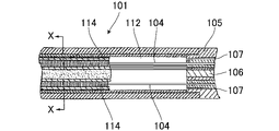
- 10 is a partial longitudinal sectional view of the catheter main body 101
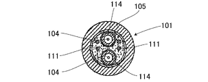
- FIG. 11 is a lateral sectional view of the catheter main body 101 taken along line XX in FIG. 10
- This electrode catheter comprises a flexible tubular catheter body 101, a tip portion 102 connected to the distal end of the catheter body, an operating handle 103 connected to the proximal end of the catheter body, and a handle near the operating handle.
- a plurality of puller wires 104 having proximal ends fixed and distal ends fixed to the tip portion (see US Pat.
- the catheter body 101 is flexible and has a structure that can be bent but cannot be compressed in the longitudinal direction. As a result, when the operating handle is rotated, the tip portion is rotated accordingly.
- the tip section 102 has a synthetic resin tube 105 that is more flexible than the catheter body, and has a deflection structure 106 inside that is biased for deflection.
- the flexure structure is a flat strip, which is made of flexible metal. By using such a belt-shaped metal, it serves as the axis of the shape and does not cause shape change, so-called heat sag, due to the lapse of intracardiac indwelling time.
- the tube 105 of the distal portion comprises a plurality of off-axis lumens 107, which are arranged in diametrically opposite positions across the flexure structure.
- a puller wire 104 is passed through each of these opposed lumens for redirecting the tip portion.
- the tubular portion is provided with another lumen 108 for inserting the electrode lead wire 111 at the distal end portion.
- the outer diameter of the tube is 8 French (approximately 2.7 mm) or less, the same as the outer diameter of the catheter body.
- a tip electrode 109 is attached to the distal end of the tip section.
- a plurality of ring electrodes 110 are attached along the longitudinal axis direction of the tip portion. Separate electrode lead wires 111 are connected to the tip and ring electrodes.
- Each lead wire passes through a lumen 108 in the tip portion, a central lumen 112 in the catheter body, and inside the operating handle, and is connected to a connector 113 provided at the end of the operating handle.
- a suitable monitor, power supply, and other equipment can be connected to this connector. Since there is no shaft inside, shape change, so-called heat sag, is likely to occur over time of intracardiac indwelling.
- Two puller wires 104 extend from the operating handle and pass through the central lumen 112 of the catheter body and into the off-axis lumen 107 of the tip section.
- a proximal end of each puller wire is fixed to the operating handle and a distal end of each puller wire is fixed to the tip electrode 109 .
- Also provided inside the catheter body are two compression coils 114 surrounding each puller wire.
- an endoscope which is a similar medical device, uses the following curved portion.
- a plurality of bending pieces that are rotatable and contact with each other are provided at the ends facing the longitudinal axis direction, and the plurality of bending pieces are connected along the longitudinal axis direction.
- the bending piece for a scope includes an inner peripheral surface and an outer peripheral surface formed around a longitudinal axis, and an annular flesh portion having a predetermined length along the longitudinal axis.
- a plurality of wire insertion portions each having a first thickness, and a plurality of wire insertion portions around the longitudinal axis;
- a thin portion having a second thickness formed thinner than the first thickness and a portion different from the thin portion between the plurality of wire insertion portions around the longitudinal axis and a thick portion formed to have a third thickness that is thicker than the second thickness (paragraph 0021 of Patent Document 2, see FIG. 2).
- the distal end portion of the catheter can be curved, but the curvature of the curve depends on the design curvature of the flexible structure. must be designed together.
- two compression coils are used inside the catheter body surrounding the first and second puller wires in order to manage the deflection of the deflection structure of the tip portion, but the load is applied to the outer tube, which is the outer tube.
- there is a problem in the reproducibility of the curved curvature because the movable shape may be distorted by the action of .
- it is necessary to manually attach each compression coil which poses a problem of low workability.
- current catheters generally pull the puller wire to forcibly bend the tube, so shortening the bending distance of the tube increases the tensile load when bending the tip, and the technical limit for bending radius is 2 cm. there were.
- the curvature of the bending portion configured by the bending piece can be changed as a whole, but since it is assumed to be used for an endoscope, it is difficult to use the electrode catheter. There is no concept of changing the curvature according to the shape of the measurement site. Therefore, there is no degree of freedom in setting the appropriate curvature for each site, and there is a problem in applying this configuration of the curved portion to the electrode catheter.
- the bending piece of the endoscope has a hollow structure for inserting forceps for the purpose of use, and does not have a structure in which electrodes can be arranged on the outer peripheral surface.
- the present invention provides an electrode catheter that can achieve a curved shape corresponding to the shape of the measurement site with good reproducibility and a desired curved shape with a high degree of freedom. is the subject. Another object of the present invention is to make it easy to manufacture and realize it at a low cost.
- the present invention provides an electrode catheter comprising a catheter body, an operation handle connected to the proximal side of the catheter body, and a distal end connected to the distal side of the catheter body, wherein the distal end has an outer circumference
- An outer tube having a plurality of electrodes spaced apart from each other on a surface thereof, a connecting shaft connected to a hollow portion of the outer tube by allowing a plurality of pieces to rotate within a predetermined range, and a tip end of the connecting shaft. and a plurality of operation wires each having one end fixed to the top member and the other end fixed to the operation handle, and the piece protrudes in a direction perpendicular to the axis of the connecting shaft.
- the electrode catheter is characterized in that the distal end portion can be bent by operating the operation wire with the operation handle. Further, the electrode catheter of the present invention may be characterized by connecting a plurality of pieces having different axial dimensions corresponding to the shape of the measurement site. Further, in the electrode catheter of the present invention, a notch is provided on the outer peripheral surface of the piece to form a gap between it and the inner peripheral surface of the outer tube, and the lead wire of the electrode is arranged in the gap. It may be
- a curved shape corresponding to the shape of the measurement site can be achieved with good reproducibility, and a desired curved shape can be achieved with a high degree of freedom.
- FIG. 1 is an external perspective view showing Example 1 of an electrode catheter of the present invention.
- FIG. FIG. 2 is a vertical cross-sectional view showing the distal end portion of the electrode catheter of Example 1; 2 is a cross-sectional view showing the distal end portion of the electrode catheter of Example 1.
- FIG. 2 is a perspective view of a piece of the electrode catheter of Example 1.
- FIG. 4 is a side view when the connecting shaft is in a straight line state;
- FIG. 4 is a side view of the connecting shaft in a curved state; It is a cross-sectional view of the tip portion provided with a bending point in front of the leading member.
- FIG. 11 is a perspective view of a piece of the electrode catheter of Example 2;
- FIG. 11 is a perspective view of a piece of the electrode catheter of Example 2; It is a Z arrow view shown in FIG. 8A.
- 1 is an external perspective view of a prior art electrode catheter;
- FIG. 1 is a partial longitudinal cross-sectional view of a catheter body according to the prior art;
- FIG. 1 is a cross-sectional view of a catheter body according to the prior art;
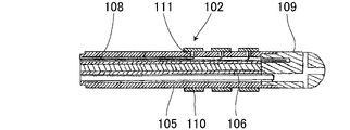
- FIG. 1 is a longitudinal cross-sectional view of the tip of an electrode catheter according to the prior art;
- FIG. 1 is an external perspective view showing Example 1 of the electrode catheter of the present invention.
- 2 is a longitudinal sectional view of the distal end portion of the electrode catheter of the present invention
- FIG. 3 is a transverse sectional view of the distal end portion taken along line AA in FIG.
- the schematic configuration of the electrode catheter 1 of the present invention is substantially the same as that of the conventional electrode catheter disclosed in Patent Document 1. That is, a flexible tubular catheter body 2, an operation handle 3 connected to the proximal side of the catheter body 2, and a flexible synthetic resin distal end 4 connected to the distal side of the catheter body 2 are provided. Prepare. Since the operating handle 3 is not different from the operating handle according to the prior art, the explanation is omitted. In the following description, specific dimensions are indicated at appropriate locations of the members so as to facilitate understanding of the structure of the members. It is neither limiting nor influential.
- the outer tube member 5 that constitutes the catheter body 2 is the same as the tube member of the prior art.
- the operation handle 3 is connected to the base end side of the tube member 5
- the distal end portion 4 is connected to the distal end side of the tube member 5 .
- the pipe member 5 is made of a flexible synthetic resin material such as polyolefin, polyamide, polyether polyamide, polyurethane or the like.
- the internal structure of the catheter body 2 differs significantly from prior art electrode catheters. That is, there are no two compression coils surrounding multiple puller wires as in the prior art.
- a support shaft 7 having a plurality of lumens is arranged inside the pipe member 5 . The proximal end of the support shaft 7 is fixed to the operation handle 3, and the distal end of the support shaft 7 is connected to a connecting shaft 8 forming the distal end of the catheter.
- the distal end portion 4 includes an outer tube 10 having a plurality of ring electrodes 9 spaced apart from each other on the outer peripheral surface, and a plurality of pieces 12 in a hollow portion 11 of the outer tube 10, which are rotatably connected to each other within a predetermined range.
- a connecting shaft 8, a leading member 13 connected to the tip of the connecting shaft 8, and a plurality of operating wires 14, 15 having one end fixed to the leading member 13 and the other end fixed to the operating handle 3. , provided.
- the outer tube 10 is manufactured using a biocompatible synthetic resin material such as polyurethane or polyethylene.
- the outer diameter of the outer tube 10 is 8 French (about 2.7 mm) or less, which is the same as the outer diameter of the catheter body 2, preferably 6 French (about 2.00 mm) or less.
- the outer tube 10 is manufactured as a tube that is more flexible than the catheter body 2 .
- a plurality of ring electrodes 9 are mounted on the outer peripheral surface of the outer tube 10 at predetermined intervals in the longitudinal direction. Although only four ring electrodes 9 are shown in FIG. 2, the number of ring electrodes 9 to be mounted is arbitrary. For example, it can be 6-20, preferably 8-12.
- Each ring electrode 9 is fixed to the outer tube 10 using a curable adhesive.
- the ring electrode is made of a metal material with good electrical conductivity such as gold, platinum, iridium, etc. Preferably, it is made of platinum or its alloy, which has excellent X-ray imaging properties when the electrode catheter is used.
- a side hole 16 is formed in the tube wall of the outer tube 10 so as to correspond to a position where the ring electrode 9 is fixed.
- a lead wire 17 is connected to a portion corresponding to the side hole 16 on the inner peripheral surface of each ring electrode 9 .
- An insulation-coated metal wire is used for the lead wire 17 , and the coating is peeled off only at the end connected to the ring electrode 9 , and the metal core wire is welded to the inner peripheral surface of the ring electrode 9 .
- a lead wire 17 inserted through the side hole 16 is introduced into a gap 18 formed between the connecting shaft 8 and the inner wall of the outer tube 10, passes through the inner space of the catheter main body 2, and passes through the connector provided on the operation handle 3. 19 is connected.
- the outer diameter of the coating of the lead wire 17 is about 0.06 to 0.1 mm, which is not large. The larger the space formed between them, the better the workability.
- a notch 25 is provided on the outer peripheral surface of the piece 12, which is a component of the connecting shaft 8, and a gap 18 having a substantially half-moon shape in cross section is formed between the piece 12 and the inner peripheral surface of the outer tube 10.
- An operation wire 15 is also inserted through the gap 18 , and the end of the operation wire 15 is fixed to the operation handle 3 .
- the connecting shaft 8 is formed by connecting a plurality of pieces 12 having the same shape so as to be rotatable with each other within a predetermined range.
- the piece 12, which is a component of the connecting shaft 8 has a rotating shaft 21 projecting in a direction orthogonal to the longitudinal axis and a bearing hole for supporting the rotating shaft 21 of the adjacent piece. 22 and an axial through hole 23 located at a position offset from the axis.
- a notch 25 is provided on one side surface of a cylindrical shape with an outer diameter of 1.7 mm in the lower half portion 24 of the piece 12 in the longitudinal direction.
- Short shafts 21 protruding in a direction perpendicular to the longitudinal axis are provided on both side surfaces perpendicular to the notch 25 , and a notch-shaped space 26 is provided around the short shaft 21 .
- a central plate portion 27 is formed in a direction perpendicular to the notch 25 in the lower half portion 24 of the piece 12 in the longitudinal direction, and short shafts 21 are formed on both sides of the central plate portion 27 so as to protrude.
- the dimension H from the center of the short shaft 21 to the lower end surface is 0.4 mm, and the thickness T of the central plate portion 27 is 0.7 mm.
- the peripheral side surface of the shaft end of the short shaft 21 is rounded in an R shape. Furthermore, an axial through hole 23 is provided at a position offset from the axis.
- a pair of support arm portions 28 are formed in the upper half portion of the piece 12 in the longitudinal direction corresponding to the position where the short shaft 21 of the lower half portion is provided. is formed as 0.7 mm.
- This interval W corresponds to the thickness T of the central plate portion 27, but is slightly larger than the thickness T of the central plate portion 27.
- a pair of support arms 28 are provided with bearing holes 22 at positions orthogonal to the longitudinal axis, and the inner diameter of the bearing holes 22 is slightly larger than the outer diameter of the short shaft 21 . Further, the interval W is 0.7 mm at the center of the bearing hole 22 and 0.71 mm at the upper end of the support arm 28 . That is, a gentle slope 29 is formed on the inner side surfaces of the pair of support arm portions 28 . This makes it easy to fit the central plate portion 27 of the lower half portion between the pair of support arm portions 28 . Also, the dimension L from the center of the bearing hole 22 to the upper end surface of the lower half is 0.55 mm.
- FIG. 5 is a side view when the connecting shaft 8 is in a straight state
- FIG. 6 is a side view when the connecting shaft 8 is bent leftward as the operation wire 14 on the left side of the connecting shaft 8 is pulled toward the base end side. It is a side view.
- the bridge 12 is integrally manufactured by injection molding using bio-compatible synthetic resin materials such as engineering plastics such as polyacetal, polyethylene, ABS, nylon, and polyurethane, and super engineering plastics such as PEEK, PPS, and PSU. .
- bio-compatible synthetic resin materials such as engineering plastics such as polyacetal, polyethylene, ABS, nylon, and polyurethane
- super engineering plastics such as PEEK, PPS, and PSU.
- the operation of connecting the pieces 12 to each other is performed by utilizing the elastic deformation of an injection-molded article using a synthetic resin material. That is, of the two pieces 12 to be connected, the center plate portion 27 of the other piece 12 is pushed into the gap W on the inner surface of the support arm portion 28 of one piece 12 to fit.
- a gentle slope 29 is formed on the inner surface of the supporting arm portion 28 of the piece, and the peripheral surface of the shaft end of the short shaft 21 provided on both sides of the central plate portion 27 of the other piece is rounded. Therefore, when another piece is pushed in the longitudinal direction, the R-shaped portion formed on the peripheral surface of the shaft end of the short shaft 21 causes the gap W on the inner side surface of the support arm portion 28 of the piece to elastically It is temporarily expanded by deformation, and it becomes possible to fit the short shaft 21 into the bearing hole 22 .
- the leading member 13 has a shape slightly extending from the lower portion of the generally hemispherical leading portion, and is connected to the upper end portion of the connecting shaft 8 . Therefore, it has a structure that can be connected to the uppermost piece that constitutes the connecting shaft 8 . That is, the side surface of the leading member 13 is provided with a pair of short shafts 31 that fit into the bearing holes 22 of the uppermost piece of the connecting shaft 8 .
- a fixing hole 32 for inserting and fixing the operation wires 14 and 15 is provided on the lower surface of the leading member 13, and the ends of the operation wires 14 and 15 are attached to the fixing hole 32 using an adhesive. Fixed.
- the outer tube 10 is provided with a wire end member 31 between the connecting shaft 8 composed of a plurality of pieces 12 and the leading member 13, and a bending point K is provided in front of the leading member 13. can be placed.
- the outer tube 10 from the leading member 13 to the wire terminating member 31 becomes flexible, and the occurrence of cardiac tamponade is expected to be reduced.
- a space is created for arranging a shape memory alloy typified by the NITI alloy, resulting in pulmonary venous arrhythmia.
- a tip shape such as a ring shape, a basket shape, or a pentaray used for measurement.
- the outer tube 10 and the wire termination member 31 are bonded with an adhesive, and the operation wires 14 and 15 are fixed to the wire termination member 31 .
- a bending point K is provided at the position of the wire termination member 31, and the operation wires 14 and 15 can be operated to bend the distal ends.
- reference numeral 32 denotes a paging electrode
- 33 denotes a paging wire.
- operation wires 14 and 15 conventionally known operation wires can be used. That is, it is possible to use a wire made of stainless steel, NITI or the like, the surface of which is coated with a low-friction material such as Teflon (registered trademark). Engineering plastic materials such as polyetheretherketone can also be used.
- a wire diameter of the operation wire is preferably 0.1 to 0.4 mm.
- the connecting shaft can be bent by operating the operating handle, and the flexible distal end portion 4 attached to the connecting shaft can be bent in accordance with the shape of the measurement site with good reproducibility.
- Example 2 is suitable for realizing a smaller diameter catheter compared to the electrode catheter of Example 1.
- catheters up to 6 French can be realized without difficulty, but it is not easy to realize catheters of 5 French (approximately 1.67 mm) or less. Therefore, in Example 2, the shape of the piece that constitutes the connecting shaft is devised so that even a small-diameter catheter can be easily realized.
- FIG. 8A, 8B, and 8C show the appearance of the piece 12 used in the electrode catheter of Example 2.
- FIG. 8A is a perspective view from the side without the notch 25, and
- FIG. 8C is a Z arrow view shown in FIG. 8A.
- This piece 25 has the same basic configuration as the piece in the first embodiment. That is, a notch 25 is provided on one side surface of the lower half portion 24 of the piece 12 in the longitudinal direction, and both side surfaces perpendicular to the notch 25 protrude in a direction orthogonal to the longitudinal axis.
- a short shaft 21 is provided.
- a notch-like space 26 is provided around the short shaft 21 , and a central plate portion 27 is formed perpendicular to the notch 25 .
- an axial through hole 23 is provided at a position offset (e) from the longitudinal axis.
- a pair of support arms 28 are formed in the upper half of the piece 12 corresponding to the position where the short shaft 21 of the lower half is provided.
- a bearing hole 22 is provided at a position perpendicular to the .
- the outer diameter of the piece 12 in the second embodiment is made smaller than the outer diameter of the piece in the first embodiment.
- the outer diameter of the bridge in Example 1 is 1.7 mm, while the diameter of the bridge in Example 2 is 1.3 mm.
- the offset (e) from the axis of the through-hole 23 in the second embodiment is smaller than the offset in the first embodiment.
- the wall thickness of the portion around the bearing hole 22 provided in the support arm 28 is reduced. is provided only.
- the ends of the short shafts 21 formed on both sides of the central plate portion 27 are chamfered 30 to form inclined surfaces on the lower side.
- this piece has a central plate portion 27 whose axial length is longer than that of the piece in the first embodiment, and correspondingly, the length of the upper half of the piece is also increased. Therefore, the overall length of the bridge is relatively long compared to the outer diameter of the bridge.
- the outer diameter of the distal end portion 4 connected to the upper end portion of the connecting shaft 8 can be reduced, so that an electrode catheter of 5 French (approximately 1.7 mm) or less can be easily realized.
- the end of the short shaft 21 is chamfered 30 to form an inclined surface on the lower side, it becomes easier to connect the pieces using the elastic deformation of the supporting arm portions 28 of the pieces to be connected.
- Catheters of the present invention can be used for cardiac pacing and/or mapping, for example, in patients with heart disease such as arrhythmias and heart failure.
- this pacing and/or mapping it is used by, but not limited to, the following methods. 1. Make an incision in the skin over the vena cava. 2. From the outside of the incision into the lumen of the vena cavae, the catheter of the present invention is traced from the vena cava vena cavae to the vein, and the electrode is placed in the lumen of the affected or affected part of the heart. 3. Connect the terminal of the catheter to a pulse generator or pacing system analyzer via an extension cable or the like. 4. Pacing and/or mapping at the diseased or monitored part of the heart. 5. After pacing and/or mapping is completed in the diseased or monitored area of the heart, the catheter of the present invention is removed. 6. The incision above the vena cava is sutured.
- a method by percutaneous puncture or incision of the subclavian vein or internal jugular vein from the left or right cephalic vein can also be used instead of the vena cava.
- the left subclavian vein or the right internal jugular vein is used.
- the electrode catheter of the present invention can be curved at its distal end with an arbitrary or desired radius of curvature, so that it can be passed through curved blood vessel lumens. Also, the electrode can be accurately brought into contact with the affected part of the heart. Therefore, highly accurate and accurate mapping and/or pacing of the affected area for electrophysiological diagnosis and/or treatment of diseases such as arrhythmia and heart failure becomes possible.
- the electrode catheter of the present invention can be used as an ablation catheter in the treatment of arrhythmia, etc., and as an esophageal temperature sensor for preventing complications caused by sugar injury due to overheating of the esophagus during cardiac ablation.
- the electrode catheter of the present invention can also be used as a defibrillation catheter that requires bending with a small radius of curvature for placement in the coronary sinus.
- the present invention has been described above with reference to examples, the present invention is not limited to the above-described examples, and various modifications can be made within the scope of the present invention.
- the number, outer diameter, and length of pieces, which are components of the connecting shaft can be changed as appropriate.
Landscapes
- Health & Medical Sciences (AREA)
- Life Sciences & Earth Sciences (AREA)
- Engineering & Computer Science (AREA)
- Veterinary Medicine (AREA)
- Public Health (AREA)
- General Health & Medical Sciences (AREA)
- Animal Behavior & Ethology (AREA)
- Surgery (AREA)
- Biomedical Technology (AREA)
- Heart & Thoracic Surgery (AREA)
- Medical Informatics (AREA)
- Molecular Biology (AREA)
- Physics & Mathematics (AREA)
- Pathology (AREA)
- Biophysics (AREA)
- Cardiology (AREA)
- Physiology (AREA)
- Nuclear Medicine, Radiotherapy & Molecular Imaging (AREA)
- Radiology & Medical Imaging (AREA)
- Plasma & Fusion (AREA)
- Otolaryngology (AREA)
- Measurement And Recording Of Electrical Phenomena And Electrical Characteristics Of The Living Body (AREA)
Priority Applications (2)
| Application Number | Priority Date | Filing Date | Title |
|---|---|---|---|
| US18/271,566 US20240138766A1 (en) | 2021-02-09 | 2022-01-18 | Electrode catheter |
| JP2022581277A JP7799326B2 (ja) | 2021-02-09 | 2022-01-18 | 電極カテーテル |
Applications Claiming Priority (2)
| Application Number | Priority Date | Filing Date | Title |
|---|---|---|---|
| JP2021018722 | 2021-02-09 | ||
| JP2021-018722 | 2021-02-09 |
Publications (1)
| Publication Number | Publication Date |
|---|---|
| WO2022172700A1 true WO2022172700A1 (ja) | 2022-08-18 |
Family
ID=82837764
Family Applications (1)
| Application Number | Title | Priority Date | Filing Date |
|---|---|---|---|
| PCT/JP2022/001576 Ceased WO2022172700A1 (ja) | 2021-02-09 | 2022-01-18 | 電極カテーテル |
Country Status (3)
| Country | Link |
|---|---|
| US (1) | US20240138766A1 (https=) |
| JP (1) | JP7799326B2 (https=) |
| WO (1) | WO2022172700A1 (https=) |
Citations (2)
| Publication number | Priority date | Publication date | Assignee | Title |
|---|---|---|---|---|
| JPH07303625A (ja) * | 1994-03-18 | 1995-11-21 | Olympus Optical Co Ltd | 磁気共鳴断層撮影装置用器具 |
| JP2003230630A (ja) * | 2001-12-31 | 2003-08-19 | Biosense Webster Inc | 2機能カテーテルハンドル |
Family Cites Families (3)
| Publication number | Priority date | Publication date | Assignee | Title |
|---|---|---|---|---|
| US6364828B1 (en) * | 2000-01-06 | 2002-04-02 | Hubert K. Yeung | Elongated flexible inspection neck |
| WO2007149841A2 (en) * | 2006-06-20 | 2007-12-27 | Aortx, Inc. | Torque shaft and torque drive |
| EP3009104B1 (en) * | 2014-10-14 | 2019-11-20 | St. Jude Medical, Cardiology Division, Inc. | Flexible catheter and methods of forming same |
-
2022
- 2022-01-18 JP JP2022581277A patent/JP7799326B2/ja active Active
- 2022-01-18 WO PCT/JP2022/001576 patent/WO2022172700A1/ja not_active Ceased
- 2022-01-18 US US18/271,566 patent/US20240138766A1/en active Pending
Patent Citations (2)
| Publication number | Priority date | Publication date | Assignee | Title |
|---|---|---|---|---|
| JPH07303625A (ja) * | 1994-03-18 | 1995-11-21 | Olympus Optical Co Ltd | 磁気共鳴断層撮影装置用器具 |
| JP2003230630A (ja) * | 2001-12-31 | 2003-08-19 | Biosense Webster Inc | 2機能カテーテルハンドル |
Also Published As
| Publication number | Publication date |
|---|---|
| JPWO2022172700A1 (https=) | 2022-08-18 |
| JP7799326B2 (ja) | 2026-01-15 |
| US20240138766A1 (en) | 2024-05-02 |
Similar Documents
| Publication | Publication Date | Title |
|---|---|---|
| JP6151452B2 (ja) | リードレス心臓装置用の送達装置及び方法 | |
| JP4209018B2 (ja) | カテーテル | |
| JP5531352B2 (ja) | カテーテルアセンブリ | |
| JP4350346B2 (ja) | マッピング組立体を有するカテーテル | |
| RU2636180C2 (ru) | Двойная петля с одинарным управляющим проводом для двухстороннего действия | |
| US6871085B2 (en) | Cardiac vein lead and guide catheter | |
| US4608986A (en) | Pacing lead with straight wire conductors | |
| US5807324A (en) | Steerable catheter | |
| CN103143114B (zh) | 可在静脉、动脉或淋巴网络中植入的,用于感测/刺激的微导线 | |
| US6728579B1 (en) | “Medical electrode lead” | |
| JP7261183B2 (ja) | カテーテルおよびその製造方法 | |
| US20180085064A1 (en) | Basket catheter conforming to organ using strain-relief elements | |
| US20030009095A1 (en) | Malleable elongated medical device | |
| JP2017035484A (ja) | 高電極密度のバスケットカテーテル | |
| US20190001143A1 (en) | Intracardiac defibrillation catheter | |
| JP2017200584A (ja) | 遠位ハブの径を小さくするためのカテーテルの可変直径遠位端の設計 | |
| JP2011500209A (ja) | 非コイル状のワイヤ構造物を備えた刺激用および検知用リード線 | |
| JP2002126096A (ja) | 電極を備えたカテーテル装置 | |
| WO2022172700A1 (ja) | 電極カテーテル | |
| JP2012192124A (ja) | 心腔内除細動カテーテル | |
| JP7167307B2 (ja) | 心腔内除細動カテーテル | |
| US11730426B2 (en) | Catheter with segmented electrodes and methods of making same | |
| WO2021070543A1 (ja) | カテーテルおよびその製造方法 | |
| JP2019122862A (ja) | 心腔内除細動カテーテル | |
| JP7701213B2 (ja) | 電極カテーテル |
Legal Events
| Date | Code | Title | Description |
|---|---|---|---|
| 121 | Ep: the epo has been informed by wipo that ep was designated in this application |
Ref document number: 22752532 Country of ref document: EP Kind code of ref document: A1 |
|
| ENP | Entry into the national phase |
Ref document number: 2022581277 Country of ref document: JP Kind code of ref document: A |
|
| NENP | Non-entry into the national phase |
Ref country code: DE |
|
| 122 | Ep: pct application non-entry in european phase |
Ref document number: 22752532 Country of ref document: EP Kind code of ref document: A1 |