WO2022172659A1 - タイミング検出装置、および、タイミング検出方法 - Google Patents
タイミング検出装置、および、タイミング検出方法 Download PDFInfo
- Publication number
- WO2022172659A1 WO2022172659A1 PCT/JP2022/000459 JP2022000459W WO2022172659A1 WO 2022172659 A1 WO2022172659 A1 WO 2022172659A1 JP 2022000459 W JP2022000459 W JP 2022000459W WO 2022172659 A1 WO2022172659 A1 WO 2022172659A1
- Authority
- WO
- WIPO (PCT)
- Prior art keywords
- code
- correlation processing
- reference code
- timing detection
- data
- Prior art date
- Legal status (The legal status is an assumption and is not a legal conclusion. Google has not performed a legal analysis and makes no representation as to the accuracy of the status listed.)
- Ceased
Links
Images








Classifications
-
- H—ELECTRICITY
- H04—ELECTRIC COMMUNICATION TECHNIQUE
- H04L—TRANSMISSION OF DIGITAL INFORMATION, e.g. TELEGRAPHIC COMMUNICATION
- H04L7/00—Arrangements for synchronising receiver with transmitter
- H04L7/04—Speed or phase control by synchronisation signals
- H04L7/041—Speed or phase control by synchronisation signals using special codes as synchronising signal
- H04L7/042—Detectors therefor, e.g. correlators, state machines
-
- H—ELECTRICITY
- H04—ELECTRIC COMMUNICATION TECHNIQUE
- H04L—TRANSMISSION OF DIGITAL INFORMATION, e.g. TELEGRAPHIC COMMUNICATION
- H04L7/00—Arrangements for synchronising receiver with transmitter
- H04L7/04—Speed or phase control by synchronisation signals
-
- H—ELECTRICITY
- H04—ELECTRIC COMMUNICATION TECHNIQUE
- H04B—TRANSMISSION
- H04B1/00—Details of transmission systems, not covered by a single one of groups H04B3/00 - H04B13/00; Details of transmission systems not characterised by the medium used for transmission
- H04B1/69—Spread spectrum techniques
- H04B1/707—Spread spectrum techniques using direct sequence modulation
- H04B1/7073—Synchronisation aspects
-
- H—ELECTRICITY
- H04—ELECTRIC COMMUNICATION TECHNIQUE
- H04J—MULTIPLEX COMMUNICATION
- H04J13/00—Code division multiplex systems
- H04J13/0007—Code type
- H04J13/0011—Complementary
Definitions
- the present invention relates to timing detection technology when receiving a digitally modulated signal.
- Patent Document 1 describes a wireless communication method and apparatus for receiving a signal modulated with a Barker code.
- an object of the present invention is to suppress side lobes during correlation processing.
- the timing detection device of the present invention comprises a main reference code generator, an auxiliary reference code generator, a first correlator, a second correlator, and a differentiator.
- the main reference code generator generates a main reference code having the same code as the synchronization code included in the received signal.
- the auxiliary reference code generator uses a part of the same code as the code for synchronization, has a code configuration different from that of the main reference code, and generates an auxiliary reference code that does not generate a main lobe during correlation processing.
- a first correlation processor performs correlation processing between the received signal and the main reference code and outputs a first correlation processing result.
- a second correlation processor performs correlation processing between the received signal and the auxiliary reference code and outputs a second correlation processing result.
- the differentiator differentiates the first correlation processing result and the second correlation processing result.
- FIG. 1 is a functional block diagram of a correlator according to an embodiment of the invention.
- FIG. 2 is a functional block diagram of the automatic ship identification device according to the embodiment of the present invention.
- FIG. 3 is a diagram showing an example of the data configuration of the automatic ship identification signal.
- FIG. 4 is a diagram showing an example of a bit array of SW (Syncword) data.
- FIG. 5A is a diagram showing an example of the bit arrangement of the main reference code according to the first embodiment
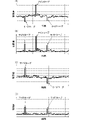
- FIG. 5B is an example of the bit arrangement of the auxiliary reference code according to the first embodiment. It is a figure which shows. 6A and 6B are diagrams showing correlation results (first correlation processing results) between the SW data and the main reference code, and FIGS. FIG.
- FIG. 10 is a diagram showing a correlation result (second correlation processing result) between data and an auxiliary reference code;
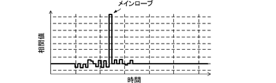
- FIG. 7 is a diagram showing the final correlation processing result (final correlation processing data).
- FIG. 8 is a flowchart illustrating an example timing detection method according to an embodiment of the present invention.
- FIG. 9A is a diagram showing an example of the bit arrangement of the main reference code according to the second embodiment, and
- FIG. 9B is an example of the bit arrangement of the auxiliary reference code according to the second embodiment. It is a figure which shows.
- FIGS. 10A and 10B are diagrams showing correlation results (second correlation processing results) between SW data and auxiliary reference codes.
- FIG. 11A is a diagram showing an example of the bit arrangement of the main reference code according to the third embodiment, and FIG.
- FIG. 11B is an example of the bit arrangement of the auxiliary reference code according to the third embodiment. It is a figure which shows.
- FIG. 12 is a diagram showing the final correlation processing result (final correlation processing data) according to the third embodiment.
- FIG. 13A is a diagram showing an example of the bit arrangement of the main reference code according to the fourth embodiment, and FIG. 13B is an example of the bit arrangement of the auxiliary reference code according to the fourth embodiment. It is a figure which shows.
- FIG. 14 is a diagram showing the final correlation processing result (final correlation processing data) according to the fourth embodiment.
- FIG. 1 is a functional block diagram of a correlator according to an embodiment of the invention.
- FIG. 2 is a functional block diagram of the automatic ship identification device according to the embodiment of the present invention.
- the automatic ship identification device 10 includes an antenna 20, a down converter 30, a coarse frequency controller 41, a symbol timing detector 42, a down converter 43, a phase controller, a tracking processor 45, and a signal detector 51. , a correlator 52 and a decoder 60 .
- the parts of the automatic ship identification system 10 other than the antenna 20 can be realized by analog circuits, digital circuits, arithmetic processing units such as computers, and the like.
- the antenna 20 receives the automatic ship identification signal and outputs the received signal to the down converter 30 .
- the down-converter 30 down-converts the received signal to a predetermined multiple frequency (for example, ten times the frequency) of the baseband signal.
- Down converter 30 outputs the down-converted received signal to frequency coarse control section 41 and signal detection section 51 .
- FIG. 3 is a diagram showing an example of the data configuration of the automatic ship identification signal.
- Ship automatic identification signals are RU (Ramp-up) data, SW (Syncword) data, LCID (Link Config ID) data, DS (Data Symbol) data, RD (Ramp-down) data, and GD (Guard) data. Consists of data.
- RU data, SW data, LCID data, DS data, RD data, and GD data are arranged in this order.
- RU data, SW data, LCID data, DS data, RD data, and GD data are data of a predetermined number of bits and a predetermined bit arrangement, respectively, and each has a predetermined modulation method (QPSK, 8PSK, 16QAM, etc.). ).
- the RU data is data representing the beginning of the data for the automatic ship identification signal.
- the SW data is data for timing detection and frequency control.
- LCID data is data representing the modulation scheme of DS data.
- the DS data is data containing various information for automatic ship identification such as a ship identification ID.
- the RD data is data of the automatic ship identification signal, more specifically, data representing the end of the DS data.
- GD data is data used for error code correction and the like.
- the SW data corresponds to the "synchronization code" of the present invention.
- FIG. 4 is a diagram showing an example of bit array of SW data.
- the SW data is composed of non-inverted codes and inverted codes.
- SW data is a code in which a non-inverted code and an inverted code are consecutive.
- An inverted code is a code obtained by inverting a non-inverted code.
- the non-inverted code is "1, 1, 1, 1, 1, 0, 0, 1, 1, 0, 1"
- the inverted code is "0, 0, 0, 0, 0,1,1,0,0,1,0,1,0”. Therefore, the SW data is "1, 1, 1, 1, 1, 0, 0, 1, 1, 0, 1, 0, 1, 0, 1, 0, 0, 0, 0, 0, 1, 1, 0, 0 , 1,0,1,0".
- the frequency coarse control unit 41 estimates and calculates the frequency deviation amount from the received signal, and performs coarse frequency control. By the processing of the frequency coarse control unit 41, for example, the frequency of the reference signal is pushed into the range of ⁇ 500 Hz to ⁇ 30 Hz with respect to the frequency of the received signal.
- the symbol timing detector 42 detects the symbol timing of the received signal after coarse control output from the frequency coarse controller 41 .
- a down converter 43 down converts the output signal of the symbol timing detector 42 to a baseband frequency.
- the phase control unit 44 performs automatic phase control on the signal down-converted to the baseband (baseband signal).
- the tracking processing unit 45 performs more accurate automatic phase control and automatic frequency control on the baseband signal output from the phase control unit 44 .
- the frequency of the reference signal is driven from the range of ⁇ 500 Hz to the range of ⁇ 30 Hz with respect to the frequency of the received signal. Therefore, convergence to a desired symbol point can be achieved with high accuracy.
- the tracking processing unit 45 outputs the signal (demodulated signal) after automatic phase control and automatic frequency control to the decoding unit 60 .
- the signal detection unit 51 detects RU data in the received signal.
- the correlator 52 performs correlation processing between the received signal and the reference code using the timing of the RU data. A specific configuration and processing of the correlator 52 will be described later.
- Correlation section 52 outputs the correlation processing result to decoding section 60 .
- the correlation processing result output from the correlator 52 has a main lobe corresponding to the slot timing of the received signal. Therefore, the correlation processing result (output correlation processing result) output from the correlator 52 enables detection of the slot timing of the received signal. That is, the correlator 52 corresponds to the "timing detection device" of the present invention.
- the decoding unit 60 uses the demodulated signal and the timing of detecting the main lobe of the correlation processing result (peak detection timing) to extract various information for automatic ship identification such as ship identification ID from DS (Data Symbol) data. Decrypt the data it contains.
- DS Data Symbol
- the correlator 52 includes a correlator 521, a correlator 522, a differentiator 523, a VCO 524, a main reference code generator 525, and an auxiliary reference code generator 526.
- the correlation processor 521 corresponds to the "first correlation processor” of the invention
- the correlation processor 522 corresponds to the "second correlation processor” of the invention.
- the VCO 524 generates a reference frequency signal for correlation processing. VCO 524 outputs a reference frequency signal to main reference code generator 525 and auxiliary reference code generator 526 .
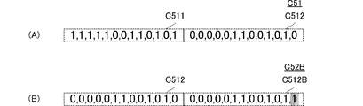
- FIG. 5A is a diagram showing an example of the bit arrangement of the main reference code according to the first embodiment
- FIG. 5B is an example of the bit arrangement of the auxiliary reference code according to the first embodiment. It is a figure which shows.
- a main reference code generator 525 uses the reference frequency signal to generate a main reference code.
- the main reference code generator 525 outputs the generated main reference code C51 to the correlation processor 521 .
- the main reference code C51 is a code in which a first code portion C511 and a second code portion C512 are continuous.
- the first code portion C511 is the same code as the non-inverted code of the SW data.
- the second code portion C512 is the same code as the inverted code of the SW data.
- the first code part C511 is "1, 1, 1, 1, 1, 0, 0, 1, 1, 0, 1, 0, 1”
- the second code part C511 is Part C512 is "0,0,0,0,0,1,1,0,0,1,0,1,0,1,0,1,0,1,0,1,0. Therefore, the main reference code C51 is "1, 1, 1, 1, 1, 0, 0, 1, 1, 0, 1, 0, 1, 0, 0, 0, 0, 1, 1, 0 , 0, 1, 0, 1, 0”, which is the same code as the SW data.
- the auxiliary reference code generator 526 uses the reference frequency signal to generate auxiliary reference codes.
- the auxiliary reference code generator 526 outputs the generated auxiliary reference code C52 to the correlation processor 522 .
- the auxiliary reference code C52 is a code in which the first code portion C511 continues.
- the first code portion C511 is the same code as the non-inverted code of the SW data.
- the first code portion C511 is "1, 1, 1, 1, 1, 0, 0, 1, 1, 0, 1". Therefore, the auxiliary reference code C52 is "1, 1, 1, 1, 1, 0, 0, 1, 1, 0, 1, 1, 1, 1, 1, 1, 0, 0, 1 , 1,0,1,0,1". That is, the auxiliary reference code C52 is configured using part of the SW data, and more specifically, is configured using the non-inverted code of the SW data.
- the correlator 521 performs correlation processing between the received signal and the main reference code, and outputs absolute value data of the first correlation processing result (first correlation processing data) to the differentiator 523 .
- the correlation processor 522 performs correlation processing on the received signal and the auxiliary reference code, and outputs the absolute value data of the second correlation processing result (second correlation processing data) to the differentiator 523 .
- the differentiator 523 differentiates the absolute value data of the first correlation processing result (first correlation processing data) and the absolute value data of the second correlation processing result (second correlation processing data) to obtain the final correlation processing result (final Correlation processing data) is output.
- FIGS. FIG. 10 is a diagram showing a correlation result (second correlation processing result) between data and an auxiliary reference code;
- FIG. 6(B) is the absolute value data of FIG. 6(A), and
- FIG. 6(D) is the absolute value data of FIG. 6(C).
- the ratio between the size of the peak generated in the correlation result and the size of the noise floor can be increased, and synchronization and frequency control can be achieved with higher accuracy.
- the first correlation processing result (first correlation processing data) obtained by performing the correlation processing using the main reference code having the same code structure as the SW data generates side lobes of a certain level along with the main lobe.
- the second correlation processing result (second correlation processing data) obtained by executing the correlation processing using the auxiliary reference code having the code structure described above is as shown in FIGS. 6(C) and 6(D). Only side lobes are generated.
- the side lobe position (time axis upper position) and the side lobe position (position on the time axis) of the correlation processing using the auxiliary reference code are the same.
- the difference between the first correlation processing result (first correlation processing data) and the second correlation processing result (second correlation processing data) is performed by the differentiator 523, so that the side lobes are canceled and suppressed, and the main lobe is only remains.
- FIG. 7 is a diagram showing the final correlation processing result (final correlation processing data). As shown in FIG. 7, there are almost no side lobes in the final correlation processing result (final correlation processing data), and the main lobe remains.
- the correlator 52 (timing detection device) can suppress side lobes during correlation processing.
- the automatic ship identification device 10 can perform synchronization with high accuracy. Further, the automatic ship identification device 10 can perform frequency control with high accuracy.
- FIG. 8 is a flowchart illustrating an example timing detection method according to an embodiment of the present invention.
- FIG. 8 describes the specific contents of each process of the flow chart shown in FIG. 8, descriptions of the parts described in the above description of the configuration will be omitted below.
- the correlation unit 52 generates a main reference code and an auxiliary reference code (S11).
- the correlator 52 performs a first correlation process using the main reference code and a second correlation process using the auxiliary reference code (S12).
- the correlation unit 52 makes a difference between the first correlation processing result and the second correlation processing result (S13).
- FIG. 9A is a diagram showing an example of the bit arrangement of the main reference code according to the second embodiment
- FIG. 9B is an example of the bit arrangement of the auxiliary reference code according to the second embodiment. It is a figure which shows.
- FIGS. 10A and 10B are diagrams showing correlation results (second correlation processing results) between SW data and auxiliary reference codes.
- FIG. 10(B) is the absolute value data of FIG. 10(A).
- the timing detection technique according to the second embodiment differs from the timing detection technique according to the first embodiment in the auxiliary reference code.
- Other contents of the timing detection technique according to the second embodiment are the same as those of the timing detection technique according to the first embodiment, and the description of the same portions will be omitted.
- the correlator 52 generates a code in which the first code portion C511 and the second code portion C512 are continuous as the main reference code C51. Therefore, the main reference code C51 is the same code as the SW data. The correlator 52 uses the main reference code C51 to perform the first correlation process.
- the correlation unit 52 generates a code in which the second code portion C512 continues as the auxiliary reference code C52A.
- the auxiliary reference code C52A is "0,0,0,0,0,1,1,0,0,1,0,1,0,0,0,0,0 ,0 , 0,1,1,0,0,1,0,1,0,1,0,1,0,1,0,1,0,1,0,1,0,1,0,1,0,1,0.1,0.1,0".
- the correlator 52 uses the auxiliary reference code C52A to perform the second correlation process.
- auxiliary reference code C52A As shown in FIGS. 10A and 10B, in the second correlation processing result (second correlation processing data), the main lobe is suppressed and the side lobe is suppressed. occurs without suppression.
- FIG. 11A is a diagram showing an example of the bit arrangement of the main reference code according to the third embodiment
- FIG. 11B is an example of the bit arrangement of the auxiliary reference code according to the third embodiment. It is a figure which shows.
- FIG. 12 is a diagram showing the final correlation processing result (final correlation processing data) according to the third embodiment.
- the timing detection technique according to the third embodiment differs from the timing detection technique according to the second embodiment in the auxiliary reference code.
- Other contents of the timing detection technique according to the third embodiment are the same as those of the timing detection technique according to the second embodiment, and the description of the same portions will be omitted.
- the correlator 52 As shown in FIG. 11(A), the correlator 52 generates a code in which the first code portion C511 and the second code portion C512 are continuous as the main reference code C51. Therefore, the main reference code C51 is the same code as the SW data. The correlator 52 uses the main reference code C51 to perform the first correlation process.
- the correlation unit 52 generates a code in which the second code portion C512 and the third code portion C512B are consecutive as the auxiliary reference code C52B.
- the third code portion C512B is a code obtained by changing some bits of the second code portion C512. More specifically, the third code portion C512B is a code obtained by inverting the last bit of the second code portion C512.
- the third code portion C512B is "0, 0, 0, 0, 0, 1, 1, 0, 0, 1, 1". Therefore, the auxiliary reference code C52B is "0,0,0,0,0,1,1,0,0,1,0,1,0,0,0,0,0,0,0,1,1,0 , 0,1,0,1,1".
- the correlator 52 uses the auxiliary reference code C52B to perform the second correlation process.
- auxiliary reference code C52B By using such an auxiliary reference code C52B, as in the second embodiment, the main lobe is suppressed and side lobes are generated without being suppressed.
- the side lobes can be suppressed without suppressing the main lobe in the final correlation processing result (final correlation processing data).
- FIG. 13A is a diagram showing an example of the bit arrangement of the main reference code according to the fourth embodiment
- FIG. 13B is an example of the bit arrangement of the auxiliary reference code according to the fourth embodiment. It is a figure which shows.
- FIG. 14 is a diagram showing the final correlation processing result (final correlation processing data) according to the fourth embodiment.
- the timing detection technique according to the fourth embodiment differs from the timing detection technique according to the second embodiment in the auxiliary reference code.
- Other contents of the timing detection technique according to the fourth embodiment are the same as those of the timing detection technique according to the second embodiment, and descriptions of the same parts are omitted.
- the correlator 52 As shown in FIG. 13(A), the correlator 52 generates a code in which the first code portion C511 and the second code portion C512 are continuous as the main reference code C51. Therefore, the main reference code C51 is the same code as the SW data. The correlator 52 uses the main reference code C51 to perform the first correlation process.
- the correlation unit 52 generates a code in which the second code portion C512 and the fourth code portion C512C are consecutive as the auxiliary reference code C52B.
- the fourth code portion C512C is a code obtained by changing some bits of the second code portion C512. More specifically, the fourth code portion C512C is a code obtained by inverting the first bit of the second code portion C512.
- the fourth code portion C512C is "1, 0, 0, 0, 0, 1, 1, 0, 0, 1, 0". Therefore, the auxiliary reference code C52B is "0,0,0,0,0,1,1,0,0,1,0,1,0,1,0,0,0,0,1,1,0 , 0, 1, 0, 1, 0".
- the correlator 52 uses the auxiliary reference code C52C to perform the second correlation process.
- auxiliary reference code C52C By using such an auxiliary reference code C52C, as in the second embodiment, the main lobe is suppressed and side lobes are generated without being suppressed.
- the side lobes can be suppressed without suppressing the main lobe in the final correlation processing result (final correlation processing data).
Landscapes
- Engineering & Computer Science (AREA)
- Computer Networks & Wireless Communication (AREA)
- Signal Processing (AREA)
- Synchronisation In Digital Transmission Systems (AREA)
- Radar Systems Or Details Thereof (AREA)
Priority Applications (3)
| Application Number | Priority Date | Filing Date | Title |
|---|---|---|---|
| JP2022581250A JP7748978B2 (ja) | 2021-02-15 | 2022-01-11 | タイミング検出装置、および、タイミング検出方法 |
| EP22752492.3A EP4293923B1 (en) | 2021-02-15 | 2022-01-11 | Timing detection device and timing detection method |
| US18/343,564 US12250020B2 (en) | 2021-02-15 | 2023-06-28 | Timing detection device and method thereof |
Applications Claiming Priority (2)
| Application Number | Priority Date | Filing Date | Title |
|---|---|---|---|
| JP2021021995 | 2021-02-15 | ||
| JP2021-021995 | 2021-02-15 |
Related Child Applications (1)
| Application Number | Title | Priority Date | Filing Date |
|---|---|---|---|
| US18/343,564 Continuation-In-Part US12250020B2 (en) | 2021-02-15 | 2023-06-28 | Timing detection device and method thereof |
Publications (1)
| Publication Number | Publication Date |
|---|---|
| WO2022172659A1 true WO2022172659A1 (ja) | 2022-08-18 |
Family
ID=82837741
Family Applications (1)
| Application Number | Title | Priority Date | Filing Date |
|---|---|---|---|
| PCT/JP2022/000459 Ceased WO2022172659A1 (ja) | 2021-02-15 | 2022-01-11 | タイミング検出装置、および、タイミング検出方法 |
Country Status (4)
| Country | Link |
|---|---|
| US (1) | US12250020B2 (https=) |
| EP (1) | EP4293923B1 (https=) |
| JP (1) | JP7748978B2 (https=) |
| WO (1) | WO2022172659A1 (https=) |
Citations (6)
| Publication number | Priority date | Publication date | Assignee | Title |
|---|---|---|---|---|
| JPH03503352A (ja) * | 1988-11-28 | 1991-07-25 | ストーノ・アークシェセルスケブ | 無線トランシーバ |
| JP2000341261A (ja) * | 1999-05-28 | 2000-12-08 | Mitsubishi Electric Corp | 同期確立方法、同期確立装置および通信システム |
| JP2002198863A (ja) * | 2000-12-27 | 2002-07-12 | Clarion Co Ltd | スペクトル拡散通信機 |
| US20040196926A1 (en) * | 2003-04-04 | 2004-10-07 | Charles Chien | Low complexity synchronization for wireless transmission |
| JP2005311532A (ja) | 2004-04-19 | 2005-11-04 | Sony Corp | 無線通信方法および装置 |
| JP2005321359A (ja) * | 2004-05-11 | 2005-11-17 | Mitsubishi Electric Corp | 符号変調パルス圧縮方式及び符号変調パルス圧縮方法 |
Family Cites Families (7)
| Publication number | Priority date | Publication date | Assignee | Title |
|---|---|---|---|---|
| US6567482B1 (en) * | 1999-03-05 | 2003-05-20 | Telefonaktiebolaget Lm Ericsson (Publ) | Method and apparatus for efficient synchronization in spread spectrum communications |
| EP1705825A1 (de) * | 2005-03-23 | 2006-09-27 | Dr. Reinhart Rudershausen | Binärer Code-Adaptivfilter für Sende-Empfangsgeräte |
| JP5453704B2 (ja) * | 2008-05-15 | 2014-03-26 | マーベル ワールド トレード リミテッド | 無線通信システムのための物理層プリアンブルフォーマット |
| US8335283B1 (en) * | 2008-11-11 | 2012-12-18 | Qualcomm Atheros, Inc. | Weak signal detection in wireless communication systems |
| US8446931B1 (en) * | 2011-04-19 | 2013-05-21 | L-3 Communications Corp | Chip timing synchronization for link that transitions between clear and spread modes |
| CN113347126B (zh) * | 2016-02-04 | 2024-02-23 | 德卡维有限责任公司 | 安全信道估计方法和系统 |
| JP6906966B2 (ja) * | 2017-01-27 | 2021-07-21 | ラピスセミコンダクタ株式会社 | 信号検出回路及び信号検出方法 |
-
2022
- 2022-01-11 WO PCT/JP2022/000459 patent/WO2022172659A1/ja not_active Ceased
- 2022-01-11 EP EP22752492.3A patent/EP4293923B1/en active Active
- 2022-01-11 JP JP2022581250A patent/JP7748978B2/ja active Active
-
2023
- 2023-06-28 US US18/343,564 patent/US12250020B2/en active Active
Patent Citations (6)
| Publication number | Priority date | Publication date | Assignee | Title |
|---|---|---|---|---|
| JPH03503352A (ja) * | 1988-11-28 | 1991-07-25 | ストーノ・アークシェセルスケブ | 無線トランシーバ |
| JP2000341261A (ja) * | 1999-05-28 | 2000-12-08 | Mitsubishi Electric Corp | 同期確立方法、同期確立装置および通信システム |
| JP2002198863A (ja) * | 2000-12-27 | 2002-07-12 | Clarion Co Ltd | スペクトル拡散通信機 |
| US20040196926A1 (en) * | 2003-04-04 | 2004-10-07 | Charles Chien | Low complexity synchronization for wireless transmission |
| JP2005311532A (ja) | 2004-04-19 | 2005-11-04 | Sony Corp | 無線通信方法および装置 |
| JP2005321359A (ja) * | 2004-05-11 | 2005-11-17 | Mitsubishi Electric Corp | 符号変調パルス圧縮方式及び符号変調パルス圧縮方法 |
Non-Patent Citations (1)
| Title |
|---|
| See also references of EP4293923A4 |
Also Published As
| Publication number | Publication date |
|---|---|
| EP4293923A1 (en) | 2023-12-20 |
| US12250020B2 (en) | 2025-03-11 |
| EP4293923B1 (en) | 2026-03-25 |
| US20230344464A1 (en) | 2023-10-26 |
| JP7748978B2 (ja) | 2025-10-03 |
| EP4293923A4 (en) | 2025-01-01 |
| JPWO2022172659A1 (https=) | 2022-08-18 |
Similar Documents
| Publication | Publication Date | Title |
|---|---|---|
| US7239675B2 (en) | GFSK receiver | |
| US20020110182A1 (en) | Code division multiple access receiver | |
| EP1102448A2 (en) | Adaptive phase demodulation | |
| WO2005010754A3 (en) | A method, system, and apparatus for adjacent-symbol error correction and detection code | |
| US20170111190A1 (en) | Non-Coherent Multi-Symbol-Delay Differential Detector | |
| US7042925B2 (en) | Correlation detection improvement by averaging spread spectrum signals | |
| JP4179418B2 (ja) | 無線受信装置 | |
| US20110188614A1 (en) | Simplified acquisition apparatus and method for a bluetooth receiver | |
| US20150139219A1 (en) | Method and apparatus for estimating frequency errors | |
| US8503594B2 (en) | Phase tracking in communications systems | |
| EP3182606B1 (en) | Blanking using signal-based thresholding schemes | |
| CN115314986A (zh) | 无线电接收机同步 | |
| JP2773562B2 (ja) | 信号系列検出方法 | |
| WO2022172659A1 (ja) | タイミング検出装置、および、タイミング検出方法 | |
| JP2020178212A (ja) | 周波数偏差検出回路、それを備えた受信機、周波数偏差検出方法、及び、周波数偏差検出プログラム | |
| JP4054032B2 (ja) | フレーム同期検出方法 | |
| JP2005278111A (ja) | デジタル放送受信装置 | |
| JP2018526875A (ja) | 特にcdma信号のようなスペクトル拡散信号のロバスト性を向上させた信号のノイズ分布整形 | |
| US20080043862A1 (en) | Receiving Apparatus and Receiving Method | |
| JP4057471B2 (ja) | 搬送波同期回路 | |
| JP4139814B2 (ja) | 周波数誤差検出方法、受信方法、及び送受信方法 | |
| JP4485736B2 (ja) | データ復元装置 | |
| JP7781087B2 (ja) | 復調装置、および、復調方法 | |
| US10484227B2 (en) | Synchronization apparatus, synchronization method for synchronizing timing | |
| JP2004134997A (ja) | パケット信号検出装置とその方法、周波数補正装置とその方法、ならびに受信装置とその方法 |
Legal Events
| Date | Code | Title | Description |
|---|---|---|---|
| 121 | Ep: the epo has been informed by wipo that ep was designated in this application |
Ref document number: 22752492 Country of ref document: EP Kind code of ref document: A1 |
|
| ENP | Entry into the national phase |
Ref document number: 2022581250 Country of ref document: JP Kind code of ref document: A |
|
| WWE | Wipo information: entry into national phase |
Ref document number: 2022752492 Country of ref document: EP |
|
| NENP | Non-entry into the national phase |
Ref country code: DE |
|
| ENP | Entry into the national phase |
Ref document number: 2022752492 Country of ref document: EP Effective date: 20230915 |
|
| WWG | Wipo information: grant in national office |
Ref document number: 2022752492 Country of ref document: EP |