WO2022172554A1 - ヒット位置推定装置、ヒット位置推定方法 - Google Patents
ヒット位置推定装置、ヒット位置推定方法 Download PDFInfo
- Publication number
- WO2022172554A1 WO2022172554A1 PCT/JP2021/042868 JP2021042868W WO2022172554A1 WO 2022172554 A1 WO2022172554 A1 WO 2022172554A1 JP 2021042868 W JP2021042868 W JP 2021042868W WO 2022172554 A1 WO2022172554 A1 WO 2022172554A1
- Authority
- WO
- WIPO (PCT)
- Prior art keywords
- hit
- unit
- estimating
- hit position
- sensor signal
- Prior art date
- Legal status (The legal status is an assumption and is not a legal conclusion. Google has not performed a legal analysis and makes no representation as to the accuracy of the status listed.)
- Ceased
Links
Images




Classifications
-
- A—HUMAN NECESSITIES
- A63—SPORTS; GAMES; AMUSEMENTS
- A63B—APPARATUS FOR PHYSICAL TRAINING, GYMNASTICS, SWIMMING, CLIMBING, OR FENCING; BALL GAMES; TRAINING EQUIPMENT
- A63B60/00—Details or accessories of golf clubs, bats, rackets or the like
- A63B60/46—Measurement devices associated with golf clubs, bats, rackets or the like for measuring physical parameters relating to sporting activity, e.g. baseball bats with impact indicators or bracelets for measuring the golf swing
-
- A—HUMAN NECESSITIES
- A63—SPORTS; GAMES; AMUSEMENTS
- A63B—APPARATUS FOR PHYSICAL TRAINING, GYMNASTICS, SWIMMING, CLIMBING, OR FENCING; BALL GAMES; TRAINING EQUIPMENT
- A63B53/00—Golf clubs
- A63B53/10—Non-metallic shafts
-
- A—HUMAN NECESSITIES
- A63—SPORTS; GAMES; AMUSEMENTS
- A63B—APPARATUS FOR PHYSICAL TRAINING, GYMNASTICS, SWIMMING, CLIMBING, OR FENCING; BALL GAMES; TRAINING EQUIPMENT
- A63B24/00—Electric or electronic controls for exercising apparatus of preceding groups; Controlling or monitoring of exercises, sportive games, training or athletic performances
- A63B24/0003—Analysing the course of a movement or motion sequences during an exercise or trainings sequence, e.g. swing for golf or tennis
- A63B24/0006—Computerised comparison for qualitative assessment of motion sequences or the course of a movement
-
- A—HUMAN NECESSITIES
- A63—SPORTS; GAMES; AMUSEMENTS
- A63B—APPARATUS FOR PHYSICAL TRAINING, GYMNASTICS, SWIMMING, CLIMBING, OR FENCING; BALL GAMES; TRAINING EQUIPMENT
- A63B24/00—Electric or electronic controls for exercising apparatus of preceding groups; Controlling or monitoring of exercises, sportive games, training or athletic performances
- A63B24/0062—Monitoring athletic performances, e.g. for determining the work of a user on an exercise apparatus, the completed jogging or cycling distance
-
- A—HUMAN NECESSITIES
- A63—SPORTS; GAMES; AMUSEMENTS
- A63B—APPARATUS FOR PHYSICAL TRAINING, GYMNASTICS, SWIMMING, CLIMBING, OR FENCING; BALL GAMES; TRAINING EQUIPMENT
- A63B69/00—Training appliances or apparatus for special sports
- A63B69/36—Training appliances or apparatus for special sports for golf
- A63B69/3617—Striking surfaces with impact indicating means, e.g. markers
- A63B69/362—Striking surfaces with impact indicating means, e.g. markers electrical or electronic
-
- A—HUMAN NECESSITIES
- A63—SPORTS; GAMES; AMUSEMENTS
- A63B—APPARATUS FOR PHYSICAL TRAINING, GYMNASTICS, SWIMMING, CLIMBING, OR FENCING; BALL GAMES; TRAINING EQUIPMENT
- A63B69/00—Training appliances or apparatus for special sports
- A63B69/36—Training appliances or apparatus for special sports for golf
- A63B69/3623—Training appliances or apparatus for special sports for golf for driving
- A63B69/3632—Clubs or attachments on clubs, e.g. for measuring, aligning
-
- A—HUMAN NECESSITIES
- A63—SPORTS; GAMES; AMUSEMENTS
- A63B—APPARATUS FOR PHYSICAL TRAINING, GYMNASTICS, SWIMMING, CLIMBING, OR FENCING; BALL GAMES; TRAINING EQUIPMENT
- A63B71/00—Games or sports accessories not covered in groups A63B1/00 - A63B69/00
- A63B71/06—Indicating or scoring devices for games or players, or for other sports activities
- A63B71/0619—Displays, user interfaces and indicating devices, specially adapted for sport equipment, e.g. display mounted on treadmills
- A63B71/0622—Visual, audio or audio-visual systems for entertaining, instructing or motivating the user
-
- A—HUMAN NECESSITIES
- A63—SPORTS; GAMES; AMUSEMENTS
- A63B—APPARATUS FOR PHYSICAL TRAINING, GYMNASTICS, SWIMMING, CLIMBING, OR FENCING; BALL GAMES; TRAINING EQUIPMENT
- A63B24/00—Electric or electronic controls for exercising apparatus of preceding groups; Controlling or monitoring of exercises, sportive games, training or athletic performances
- A63B24/0062—Monitoring athletic performances, e.g. for determining the work of a user on an exercise apparatus, the completed jogging or cycling distance
- A63B2024/0068—Comparison to target or threshold, previous performance or not real time comparison to other individuals
-
- A—HUMAN NECESSITIES
- A63—SPORTS; GAMES; AMUSEMENTS
- A63B—APPARATUS FOR PHYSICAL TRAINING, GYMNASTICS, SWIMMING, CLIMBING, OR FENCING; BALL GAMES; TRAINING EQUIPMENT
- A63B71/00—Games or sports accessories not covered in groups A63B1/00 - A63B69/00
- A63B71/06—Indicating or scoring devices for games or players, or for other sports activities
- A63B71/0619—Displays, user interfaces and indicating devices, specially adapted for sport equipment, e.g. display mounted on treadmills
- A63B71/0622—Visual, audio or audio-visual systems for entertaining, instructing or motivating the user
- A63B2071/0625—Emitting sound, noise or music
-
- A—HUMAN NECESSITIES
- A63—SPORTS; GAMES; AMUSEMENTS
- A63B—APPARATUS FOR PHYSICAL TRAINING, GYMNASTICS, SWIMMING, CLIMBING, OR FENCING; BALL GAMES; TRAINING EQUIPMENT
- A63B2102/00—Application of clubs, bats, rackets or the like to the sporting activity ; particular sports involving the use of balls and clubs, bats, rackets, or the like
- A63B2102/32—Golf
-
- A—HUMAN NECESSITIES
- A63—SPORTS; GAMES; AMUSEMENTS
- A63B—APPARATUS FOR PHYSICAL TRAINING, GYMNASTICS, SWIMMING, CLIMBING, OR FENCING; BALL GAMES; TRAINING EQUIPMENT
- A63B2220/00—Measuring of physical parameters relating to sporting activity
- A63B2220/10—Positions
- A63B2220/13—Relative positions
-
- A—HUMAN NECESSITIES
- A63—SPORTS; GAMES; AMUSEMENTS
- A63B—APPARATUS FOR PHYSICAL TRAINING, GYMNASTICS, SWIMMING, CLIMBING, OR FENCING; BALL GAMES; TRAINING EQUIPMENT
- A63B2220/00—Measuring of physical parameters relating to sporting activity
- A63B2220/10—Positions
- A63B2220/16—Angular positions
-
- A—HUMAN NECESSITIES
- A63—SPORTS; GAMES; AMUSEMENTS
- A63B—APPARATUS FOR PHYSICAL TRAINING, GYMNASTICS, SWIMMING, CLIMBING, OR FENCING; BALL GAMES; TRAINING EQUIPMENT
- A63B2220/00—Measuring of physical parameters relating to sporting activity
- A63B2220/62—Time or time measurement used for time reference, time stamp, master time or clock signal
-
- A—HUMAN NECESSITIES
- A63—SPORTS; GAMES; AMUSEMENTS
- A63B—APPARATUS FOR PHYSICAL TRAINING, GYMNASTICS, SWIMMING, CLIMBING, OR FENCING; BALL GAMES; TRAINING EQUIPMENT
- A63B2220/00—Measuring of physical parameters relating to sporting activity
- A63B2220/80—Special sensors, transducers or devices therefor
- A63B2220/803—Motion sensors
-
- A—HUMAN NECESSITIES
- A63—SPORTS; GAMES; AMUSEMENTS
- A63B—APPARATUS FOR PHYSICAL TRAINING, GYMNASTICS, SWIMMING, CLIMBING, OR FENCING; BALL GAMES; TRAINING EQUIPMENT
- A63B2220/00—Measuring of physical parameters relating to sporting activity
- A63B2220/80—Special sensors, transducers or devices therefor
- A63B2220/83—Special sensors, transducers or devices therefor characterised by the position of the sensor
- A63B2220/833—Sensors arranged on the exercise apparatus or sports implement
-
- A—HUMAN NECESSITIES
- A63—SPORTS; GAMES; AMUSEMENTS
- A63B—APPARATUS FOR PHYSICAL TRAINING, GYMNASTICS, SWIMMING, CLIMBING, OR FENCING; BALL GAMES; TRAINING EQUIPMENT
- A63B2225/00—Miscellaneous features of sport apparatus, devices or equipment
- A63B2225/50—Wireless data transmission, e.g. by radio transmitters or telemetry
-
- A—HUMAN NECESSITIES
- A63—SPORTS; GAMES; AMUSEMENTS
- A63B—APPARATUS FOR PHYSICAL TRAINING, GYMNASTICS, SWIMMING, CLIMBING, OR FENCING; BALL GAMES; TRAINING EQUIPMENT
- A63B2225/00—Miscellaneous features of sport apparatus, devices or equipment
- A63B2225/74—Miscellaneous features of sport apparatus, devices or equipment with powered illuminating means, e.g. lights
Definitions
- the present invention relates to technology for detecting the hit position of the ball on the club head.
- Patent Document 1 describes a swing analysis device.
- a swing analysis device includes a sensor, a posture calculator, and a corrector.
- the sensor is attached to the shaft of the golf club and outputs shaft acceleration information, angular velocity information, and strain information.
- the posture calculator calculates the posture of the golf club during the swing based on the acceleration information and the angular velocity information.
- the correction unit corrects the posture information at the time of impact based on the distortion information.
- an object of the present invention is to provide a technique for estimating the hit position of the ball on the club head.
- a hit position estimation device of the present invention includes a sensor and a computing unit.
- the sensor is not attached to the striking part but is attached to the pillar, and outputs a sensor signal including the torsion of the pillar, with respect to the sports equipment having the pillar and the striking part connected to the pillar.
- the calculation unit uses the sensor signal to estimate the position at which the striking part receives pressure from the outside from the torsion component when the striking part receives pressure from the outside.
- the output of the sensor attached to the columnar portion is used to detect the hitting portion.
- a position (hit position) receiving pressure from the outside is estimated.
- the hit position of the desired object on the hitting part for example, the hit position of the ball on the head if the sports equipment is a golf club.
- FIG. 1 is a functional block diagram of a hit position estimation device according to the first embodiment.
- FIG. 2 is a diagram showing an example of the attachment state of the first electronic device of the hit position estimating device to the golf club.
- FIG. 3 is a schematic top view of a golf club head for defining bends and twists.
- FIG. 4 is a functional block diagram of a feature data extraction unit according to the first embodiment;
- FIG. 5 is a functional block diagram showing an example of the first aspect of the estimating section.
- FIG. 6 is a front view of the head showing an example of estimated hit positions.
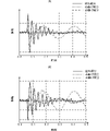
- FIG. 7A is a graph showing an example of the waveform of the sensor signal when the toe side of the head (position Pt in FIG. 6) is hit, and FIG.
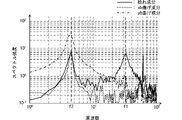
- FIG. 8 is a graph showing the frequency spectrum in the case of FIG. 7(A).
- FIG. 9 is a graph showing the relationship between the value of the mounted part and the threshold.
- FIG. 10 is a functional block diagram showing an example of the second mode of the estimating section.
- FIG. 11 is a coordinate diagram for explaining the concept of setting the regression equation.
- FIG. 12 is a flowchart illustrating a hit position estimation method according to an embodiment of the present invention.
- FIG. 13A is a functional block diagram of a hit position estimation device according to the second embodiment, and FIG.
- FIG. 1 is a functional block diagram of a hit position estimation device according to the first embodiment.
- FIG. 2 is a diagram showing an example of the attachment state of the first electronic device of the hit position estimating device to the golf club.
- the hit position estimation device 10 includes a first electronic device 11 and a second electronic device 12.
- the first electronic device 11 and the second electronic device 12 are separate entities.
- the first electronic device 11 includes a sensor 20 , a feature data extraction section 31 and a communication section 341 .
- the sensor 20 includes a sensor element 21 and a sensor signal generator 22 .
- the sensor signal generation unit 22, the feature data extraction unit 31, and the communication unit 341 are realized by, for example, a plurality of electronic circuit elements such as ICs mounted on a circuit board or the like.
- the sensor element 21 includes a film-like main body having piezoelectricity and a detection electrode.
- the main body is made mainly of polylactic acid, for example, and is polarized according to bending and twisting. At this time, the direction of polarization changes according to the direction of bending and the direction of twisting, and the magnitude of electric charge generated by polarization differs according to the magnitude of bending and the magnitude of twisting.
- the detection electrodes are attached to the surface of the main body. At this time, the detection electrodes are attached to the main body so as to be able to output electric charges due to bending and electric charges due to twisting.
- the sensor signal generator 22 is realized by a predetermined electronic circuit.
- the sensor signal generator 22 includes, for example, an integration circuit, and generates a sensor signal, which is a voltage signal, from charges generated in the sensor element 21 .
- the golf club 90 has a shaft 91 and a head 92 .
- the shaft 91 is a straight rod.
- the head 92 is installed at one end in the direction in which the shaft 91 extends.
- the end of the shaft 91 opposite to the mounting position of the head 92 is a grip.
- the golf club 90 corresponds to the "sports equipment” of the present invention
- the shaft 91 corresponds to the "columnar portion” of the present invention
- the head 92 corresponds to the “hitting portion” of the present invention.
- the golf ball hit by this golf club 90 corresponds to the "desired object" of the present invention.
- the first electronic device 11 is attached to the shaft 91 .
- the first electronic device 11 is attached near the grip of the shaft 91, but the mounting position of the first electronic device 11 on the shaft 91 is not limited to this.
- the sensor 20 outputs a sensor signal corresponding to bending and twisting of the shaft 91 .
- the sensor signal includes a bending component Sxb in the xb direction, a bending component Syb in the yb direction, and a torsional component S ⁇ tw.
- the bending component Sxb in the xb direction, the bending component Syb in the yb direction, and the twisting component S ⁇ tw are individually detected.
- FIG. 3 is a schematic top view of a golf club head for defining bends and twists.
- the xb direction is a direction parallel to the face 921 of the head 92 .
- the shaft 91 is attached to one end of the head 92 in the xb direction.
- the side of the head 92 to which the shaft 91 is attached is called the heel side, and the side opposite to the side to which the shaft 91 is attached is called the toe side.
- the heel side is a positive area and the toe side is a negative area. That is, the bending component Sxb in the xb direction takes a positive value with a larger absolute value as the shoe bends more toward the heel side, and takes a negative value with a larger absolute value as it bends more toward the toe side.
- the yb direction is a direction perpendicular to the face 921 of the head 92 .
- the face 921 side is a negative area
- the side opposite to the face 921 side is a positive area. That is, the bending component Syb in the yb direction takes a positive value with a larger absolute value as the ball bends more toward the side opposite to the face 921 side, and takes a negative value with a larger absolute value as the ball bends more toward the face 921 side.
- the twist ⁇ tw is the direction of rotation about the axis perpendicular to the xb direction and the yb direction.
- the twist component S ⁇ tw takes a positive value when the heel of the head 92 is in front of the toe (negative direction in the yb direction), and takes a negative value when the heel of the head 92 is behind the toe (in the positive direction in the yb direction). become.
- the absolute value of the twist component S ⁇ tw increases.
- the sensor signal generation unit 22 of the sensor 20 outputs a sensor signal including the bending component Sxb in the xb direction, the bending component Syb in the yb direction, and the twisting component S ⁇ tw that change in this way to the feature data extraction unit 31. do.
- the definitions of the bending component Sxb in the xb direction, the bending component Syb in the yb direction, and the torsion component S ⁇ tw are not limited to those described above. Other definitions are possible, provided that the bending of the shaft 91 in the vertical direction and the twisting of the shaft 91 can be univocally defined.
- FIG. 4 is a functional block diagram of a feature data extraction unit according to the first embodiment
- the feature data extraction unit 31 includes an AD conversion unit 310, a hit timing detection unit 311, and a hit position estimation data extraction unit 312.
- the AD converter 310 AD-converts (analog-to-digital converts) the sensor signal.
- the AD converter 310 outputs the digitized sensor signal to the hit timing detector 311 .
- the hit timing detection unit 311 detects, for example, when the absolute value of the sensor signal changes significantly, and detects this detection timing as the hit timing.
- the hit timing detection section 311 outputs the sensor signal and the hit timing to the hit position estimation data extraction section 312 .
- the hit position estimation data extraction unit 312 extracts a sensor signal of a predetermined length of time from the hit timing and outputs it as hit position estimation data.
- the communication unit 341 transmits the hit position estimation data to the communication unit 342 of the second electronic device 12 .
- the second electronic device 12 is implemented by, for example, an information processing mobile terminal such as a smart phone, which is not installed in the golf club 90, or an information processing device such as a personal computer.
- the second electronic device 12 includes a communication unit 342, a waveform processing unit 32, an estimation unit 33, and a notification unit 40.
- the communication unit 342 receives hit position estimation data from the communication unit 341 of the first electronic device 11 .
- the communication unit 342 outputs the hit position estimation data to the waveform processing unit 32 .
- the waveform processing unit 32 executes complex Fourier transform processing on the hit position estimation data. Thereby, the waveform processing section 32 generates a complex frequency spectrum (complex frequency component) of the hit position estimation data. The waveform processing section 32 outputs the complex frequency spectrum of the hit position estimation data to the estimation section 33 .
- the estimating unit 33 roughly uses at least the twist component S ⁇ tw to estimate the hit position and outputs it to the notification unit 40 .
- the specific configuration and estimation concept of the estimation unit 33 will be described later.
- the notification unit 40 is realized by a display, a speaker, a lamp, and the like.
- the notification unit 40 executes notification according to the hit position. For example, if the notification unit 40 is a display, the notification unit 40 displays an image of the face 921 of the head 92 and an estimated hit position mark superimposed on this image. Also, if the notification unit 40 is a speaker, the notification unit 40 emits sound by changing the type of sound according to the hit position. Also, when the notification unit 40 is a lamp, the notification unit 40 lights, blinks, or emits light in a color corresponding to the hit position.
- the estimation unit 33 estimates hit positions using the complex frequency spectrum of the hit position estimation data.
- FIG. 5 is a functional block diagram showing an example of the first aspect of the estimating unit.
- the estimation unit 33 includes a specific frequency component extraction unit 331 and a comparison determination unit 332. A more specific concept of estimating the hit position executed by the estimating unit 33 will be described later.
- the specific frequency component extraction unit 331 extracts specific frequency components in the complex frequency spectrum of hit position estimation data. More specifically, the specific frequency component extraction unit 331 extracts the real part value Retwf1 of the specific frequency component (frequency f1 (for example, approximately 32.0 Hz)) in the complex frequency spectrum of the twist component S ⁇ tw from the hit position estimation data. Extract.
- the specific frequency is set based on the shape and material of the golf club 90, more specifically, the shape and material of the head 92 and the shape and material of the shaft 91, and the ball hits a part other than the center of the face 921. Sometimes set by the frequency at which peaks of a given level occur.
- the specific frequency component extraction unit 331 outputs the value Retwf1 of the real part of the specific frequency component of the twist component S ⁇ tw to the comparison determination unit 332 .
- the specific frequency component extractor 331 corresponds to the "spectrum intensity calculator" of the present invention.
- the comparison/determination unit 332 stores in advance a threshold value for estimating the hit position.
- the comparison determination unit 332 compares the value Retwf1 of the real part of the specific frequency component of the twist component S ⁇ tw with a threshold value for estimating the hit position to estimate the hit position.
- FIG. 6 is a front view of the head showing an example of estimated hit positions.
- FIG. 7A is a graph showing an example of the waveform of the sensor signal when the toe side of the head (position Pt in FIG. 6) is hit, and FIG. It is an example of a waveform diagram of a sensor signal when a position Ph) is hit.
- the solid line indicates the torsional component S ⁇ tw
- the dashed line indicates the bending component Sxb in the xb direction
- the dashed line indicates the bending component Syb in the yb direction.
- FIG. 8 is a graph showing the frequency spectrum in the case of FIG. 7(A).
- FIG. 9 is a graph showing the relationship between the value of the mounted part and the threshold.
- the behavior of the torsion component S ⁇ tw is large. different. More specifically, when the ball hits the toe-side position Pt, the torsion component S ⁇ tw greatly fluctuates to a positive value immediately after the timing of the hit, changes to a negative value, and then changes at a predetermined cycle. Attenuates gradually while vibrating. On the other hand, when the ball hits the heel side position Ph, the torsion component S ⁇ tw greatly fluctuates to a negative value immediately after the hit timing, changes to a positive value, and then gradually vibrates at a predetermined cycle. attenuates to
- the head 92 is displaced and the shaft 91 is twisted when the position where the ball hits deviates from the center position Pc (see FIG. 6) of the face 921 at the timing of hitting. More specifically, when the ball hits the toe-side position Pt, the toe-side is behind the heel-side, and a positive twist occurs in the shaft 91 accordingly. On the other hand, if the ball hits the heel side position Ph, the toe side will be forward of the heel side, and the shaft 91 will be twisted with a negative value accordingly.
- the estimation unit 33 uses this feature to estimate the hit position using the value of the real part of the complex frequency spectrum. More specifically, as described above, the torsion component S ⁇ tw attenuates while vibrating at a specific frequency. Therefore, by obtaining the complex frequency spectrum, it is possible to extract the specific frequency component of this torsion component S ⁇ tw. For example, as shown in FIG. 8, the spectral intensity of a specific frequency f1 (eg, 32 Hz) can be obtained, and changes in the twist component S ⁇ tw due to hits can be detected more reliably.
- a specific frequency f1 eg, 32 Hz
- the specific frequency component extraction unit 331 extracts the spectrum intensity of this specific frequency f1 (eg, 32 Hz).
- the value Retwf1 of the real part of the spectral intensity of the specific frequency f1 changes according to the hit position. More specifically, when the toe-side position Pt is hit, the value Retwf1 of the real part becomes a positive value larger than the first threshold Th1. On the other hand, when the position Ph on the heel side is hit, the value Retwf1 of the real part becomes a negative value smaller than the second threshold Th2. Also, when the center position Pc is hit, the value Retwf1 of the real part becomes a value between the first threshold Th1 and the second threshold Th2.
- the first threshold Th1 and the second threshold Th2 correspond to the "determination threshold" of the present invention.
- the comparison determination unit 332 compares the value Retwf1 of the real part with the first threshold Th1 and the second threshold Th2. If the value Retwf1 of the real part is greater than or equal to the first threshold value Th1, the comparison determination unit 332 determines that the toe-side position Pt has been hit. If the value Retwf1 of the real part is equal to or less than the second threshold Th2, the comparison determination unit 332 determines that the position Ph on the heel side has been hit. If the value Retwf1 of the real part is greater than the second threshold Th2 and less than the first threshold Th1, the comparison determination unit 332 determines that the center position Pc has been hit.
- the hit position estimation device 10 can detect the movement of the head 92 by attaching the sensor element 21 to the shaft 91 without attaching the sensor element 21 to the head 92 .
- the hit position of the ball can be estimated.
- the hit position estimating device 10 calculates the complex frequency spectrum, extracts the spectrum intensity of the specific frequency, and uses it to more reliably detect the change in the twist component due to the hit. This allows the hit position estimation device 10 to more reliably estimate the hit position.
- the hit position estimating device 10 has shown an aspect using the complex frequency spectrum, it is also possible to use the measured value of the twist component S ⁇ tw as it is. In this case, the hit position estimating device 10 compares the measured value of the twist component S ⁇ tw with the threshold to estimate the hit position. Note that the concept of setting the threshold is the same as in the case of using the complex frequency spectrum described above, and the description thereof is omitted. In this case, the hit position estimation device 10 can omit the waveform processing section 32 .
- FIG. 10 is a functional block diagram showing an example of the second mode of the estimating section.
- the estimation unit 33A includes a specific frequency component extraction unit 331A and a regression analysis unit 333.
- the specific frequency component extraction unit 331A extracts specific frequency components in the complex frequency spectrum of hit position estimation data. More specifically, the specific frequency component extraction unit 331 extracts a plurality of specific frequency components in the complex frequency spectrum of the bending component Sxb in the xb direction, the bending component Syb in the yb direction, and the twisting component S ⁇ tw from the hit position estimation data. (complex amplitudes Axbf1r, Axbf1i, Aybf1r, Aybf1i, A ⁇ f1r, A ⁇ f1i, Axbf2r, Axbf2i, at frequency f1 (see FIG. 8, for example, about 32.0 Hz) and frequency f2 (see FIG. 8, for example, about 4.5 Hz)) Aybf2r, Aybf2i, A ⁇ f2r, and A ⁇ f2i are extracted.
- the complex amplitudes Axbf1r and Axbf1i are the real and imaginary parts of the bending component Sxb of the frequency f1 in the xb direction
- the complex amplitudes Aybf1r and Aybf1i are the real and imaginary parts of the bending component Syb of the frequency f1 in the yb direction
- the complex amplitudes A ⁇ f1r and A ⁇ f1i are the real and imaginary parts of the twist component S ⁇ tw of the frequency f1.
- the complex amplitudes Axbf2r and Axbf2i are the real and imaginary parts of the bending component Sxb of the frequency f2 in the xb direction
- the complex amplitudes Aybf2r and Aybf2i are the real and imaginary parts of the bending component Syb of the frequency f2 in the yb direction
- the complex amplitudes A ⁇ f2r and A ⁇ f2i are the real and imaginary parts of the twist component S ⁇ tw of the frequency f2.
- the specific frequency component extraction unit 331A outputs the complex amplitudes Axbf1r, Axbf1i, Aybf1r, Aybf1i, A ⁇ f1r, A ⁇ f1i, Axbf2r, Axbf2i, Aybf2r, Aybf2i, A ⁇ f2r, A ⁇ f2i to the regression analysis unit 333.
- the regression analysis unit 333 stores regression equations having regression coefficients and intercepts calculated in advance by experiments.
- the regression coefficient and intercept of the regression equation are set as follows.
- FIG. 11 is a coordinate diagram for explaining the concept of setting the regression equation.
- a two-dimensional target variable consisting of a hit position p and a hit direction D is set for the face 921 .
- the center position Pc of the face 921 is set to 0 (p)
- the heel side position Ph is set to +1 (p)
- the toe side position Pt is set to -1 (p). be done.
- the hit direction D the direction perpendicular to the face 921 is set to 0 (D)
- the direction from the heel side is set to +1 (D)
- the direction from the toe side is set to -1 (D). be done.
- the ball is hit a predetermined number of times against the face 921 experimentally.
- the hit position and hit direction of the ball are set according to the objective variables described above.
- the experimental complex amplitudes Axbf1rt, Axbf1it, Aybf1rt, Aybf1it, A ⁇ f1rt, A ⁇ f1it, Axbf2rt, Axbf2it, Aybf2rt, Aybf2it, A ⁇ f2rt, A ⁇ f2it are obtained.
- the regression analysis unit 333 converts the complex amplitudes Axbf1r, Axbf1i, Aybf1r, Aybf1i, A ⁇ f1r, A ⁇ f1i, Axbf2r, Axbf2i, Aybf2r, Aybf2i, A ⁇ f2r, and A ⁇ f2i from the specific frequency component extraction unit 331A into optimized regression coefficients and Substitute into the set regression equation. Thereby, the regression analysis unit 333 estimates the hit position of the ball.
- the estimation unit 33A can estimate not only the hit position but also the hit direction.
- At least one of the bending component Sxb in the xb direction and the bending component Syb in the yb direction may not be used in the regression analysis. Thereby, for example, the estimated speed can be improved.
- FIG. 12 is a flow chart showing the hit position estimation method according to the embodiment of the present invention. The specific contents of each process in the flowchart shown in FIG. 12 have been described in the description of the configuration above, and the detailed description will be omitted except where necessary.
- the sensor 20 senses bending and twisting of the shaft 91 of the golf club 90 (S11).
- the sensor 20 generates a sensor signal from the sensing result (S12).
- the feature data extraction unit 31 extracts feature data for estimating the hit position in the sensor signal (S13).
- the waveform processing unit 32 waveform-processes the feature data for estimating the hit position (S14). More specifically, the waveform processing section 32 performs complex Fourier transform processing on the feature data for estimating the hit position.
- the estimation unit 33 estimates the hit position using the result of the complex Fourier transform process (S15).
- FIG. 13A is a functional block diagram of a hit position estimation device according to the second embodiment, and FIG.
- the hit position estimation device 10B is a single It differs in that it is formed in a housing (electronic device).
- Other configurations of the hit position estimation device 10B are the same as those of the hit position estimation device 10, and the description of the same parts is omitted.
- the hit position estimation device 10B is attached to the shaft 91 so that the sensor element 21 is arranged along the surface of the shaft 91 and the sensor element 21 is deformed according to the displacement of the shaft 91 .
- the sensor 20 includes a sensor element 21 and a sensor signal generator 22 .
- the sensor 20 outputs a sensor signal to the calculator 30 .
- the calculation unit 30 includes a feature data extraction unit 31, a waveform processing unit 32, and an estimation unit 33.
- the calculation unit 30 estimates the hit position using at least the twist component S ⁇ tw included in the sensor signal, as described in the first embodiment.
- the calculation section 30 outputs the hit position to the notification section 40 .
- the notification unit 40 notifies according to the hit position.
- the notification unit 40 since the hit position estimation device 10B is attached to the shaft 91, the notification unit 40 is preferably small, such as a small speaker.
- the notification unit 40 may be a lamp or the like.
- the notification unit 40 may be provided separately.
- the display unit of the smartphone may be used as the notification unit 40 and the hit position may be output to the smartphone.
Landscapes
- Health & Medical Sciences (AREA)
- General Health & Medical Sciences (AREA)
- Physical Education & Sports Medicine (AREA)
- Engineering & Computer Science (AREA)
- Multimedia (AREA)
- Human Computer Interaction (AREA)
- Golf Clubs (AREA)
Priority Applications (2)
| Application Number | Priority Date | Filing Date | Title |
|---|---|---|---|
| JP2022581197A JP7548344B2 (ja) | 2021-02-10 | 2021-11-24 | ヒット位置推定装置、ヒット位置推定方法 |
| US18/446,770 US20230381615A1 (en) | 2021-02-10 | 2023-08-09 | Hit position estimation device and hit position estimation method |
Applications Claiming Priority (2)
| Application Number | Priority Date | Filing Date | Title |
|---|---|---|---|
| JP2021019522 | 2021-02-10 | ||
| JP2021-019522 | 2021-02-10 |
Related Child Applications (1)
| Application Number | Title | Priority Date | Filing Date |
|---|---|---|---|
| US18/446,770 Continuation US20230381615A1 (en) | 2021-02-10 | 2023-08-09 | Hit position estimation device and hit position estimation method |
Publications (1)
| Publication Number | Publication Date |
|---|---|
| WO2022172554A1 true WO2022172554A1 (ja) | 2022-08-18 |
Family
ID=82838599
Family Applications (1)
| Application Number | Title | Priority Date | Filing Date |
|---|---|---|---|
| PCT/JP2021/042868 Ceased WO2022172554A1 (ja) | 2021-02-10 | 2021-11-24 | ヒット位置推定装置、ヒット位置推定方法 |
Country Status (3)
| Country | Link |
|---|---|
| US (1) | US20230381615A1 (https=) |
| JP (1) | JP7548344B2 (https=) |
| WO (1) | WO2022172554A1 (https=) |
Cited By (1)
| Publication number | Priority date | Publication date | Assignee | Title |
|---|---|---|---|---|
| JP2023023605A (ja) * | 2021-08-05 | 2023-02-16 | 住友ゴム工業株式会社 | ゴルフスイングの分析システム及び分析方法 |
Citations (4)
| Publication number | Priority date | Publication date | Assignee | Title |
|---|---|---|---|---|
| US20090131196A1 (en) * | 2006-08-28 | 2009-05-21 | Origin, Inc. | Face markings for golf clubs |
| JP2012130414A (ja) * | 2010-12-20 | 2012-07-12 | Seiko Epson Corp | スイング分析装置 |
| JP2015126813A (ja) * | 2013-12-27 | 2015-07-09 | カシオ計算機株式会社 | 状態推定装置、状態推定方法及びプログラム |
| JP2017213145A (ja) * | 2016-05-31 | 2017-12-07 | ダンロップスポーツ株式会社 | 打点推定装置 |
Family Cites Families (8)
| Publication number | Priority date | Publication date | Assignee | Title |
|---|---|---|---|---|
| US3806131A (en) * | 1972-03-29 | 1974-04-23 | Athletic Swing Measurement | Swing measurement and display system for athletic implements |
| US3792863A (en) * | 1972-05-30 | 1974-02-19 | Athletic Swing Measurement | Swing measurement system and method employing simultaneous multi-swing display |
| JPH09215808A (ja) * | 1995-12-07 | 1997-08-19 | Hokuriku Electric Ind Co Ltd | スイング型運動用具の練習装置及びスイング型運動用具 |
| US5951410A (en) * | 1997-01-03 | 1999-09-14 | True Temper Sports, Inc. | Apparatus for obtaining compound bending data of a golf club |
| JP2946331B1 (ja) * | 1998-09-07 | 1999-09-06 | 日本シャフト株式会社 | ゴルフクラブシャフト |
| WO2009069698A1 (ja) * | 2007-11-27 | 2009-06-04 | Mugen Inc. | 打撃位置検出装置、打撃位置検出方法、及び打撃位置検出装置の製造方法 |
| JP4743292B2 (ja) * | 2009-02-16 | 2011-08-10 | 美津濃株式会社 | スイング分析装置およびゴルフクラブシャフト選定システム |
| JP6259206B2 (ja) * | 2013-05-31 | 2018-01-10 | 株式会社ブリヂストン | ゴルフスイング分類方法、ゴルフクラブ選定方法、ゴルフスイング分類装置、及びゴルフスイング分類システム |
-
2021
- 2021-11-24 WO PCT/JP2021/042868 patent/WO2022172554A1/ja not_active Ceased
- 2021-11-24 JP JP2022581197A patent/JP7548344B2/ja active Active
-
2023
- 2023-08-09 US US18/446,770 patent/US20230381615A1/en active Pending
Patent Citations (4)
| Publication number | Priority date | Publication date | Assignee | Title |
|---|---|---|---|---|
| US20090131196A1 (en) * | 2006-08-28 | 2009-05-21 | Origin, Inc. | Face markings for golf clubs |
| JP2012130414A (ja) * | 2010-12-20 | 2012-07-12 | Seiko Epson Corp | スイング分析装置 |
| JP2015126813A (ja) * | 2013-12-27 | 2015-07-09 | カシオ計算機株式会社 | 状態推定装置、状態推定方法及びプログラム |
| JP2017213145A (ja) * | 2016-05-31 | 2017-12-07 | ダンロップスポーツ株式会社 | 打点推定装置 |
Cited By (2)
| Publication number | Priority date | Publication date | Assignee | Title |
|---|---|---|---|---|
| JP2023023605A (ja) * | 2021-08-05 | 2023-02-16 | 住友ゴム工業株式会社 | ゴルフスイングの分析システム及び分析方法 |
| JP7714949B2 (ja) | 2021-08-05 | 2025-07-30 | 住友ゴム工業株式会社 | ゴルフスイングの分析システム及び分析方法 |
Also Published As
| Publication number | Publication date |
|---|---|
| US20230381615A1 (en) | 2023-11-30 |
| JPWO2022172554A1 (https=) | 2022-08-18 |
| JP7548344B2 (ja) | 2024-09-10 |
Similar Documents
| Publication | Publication Date | Title |
|---|---|---|
| JP7570465B2 (ja) | コンピュータが実行する方法 | |
| US9387361B2 (en) | Swing analyzing apparatus | |
| US20150343293A1 (en) | Measuring device for detecting a hitting movement of a hitting implement, training device, and method for training a hitting movement | |
| CN102686285B (zh) | 增强球拍运动中的表现的方法和设备 | |
| JP5773121B2 (ja) | スイング分析装置及びスイング分析プログラム | |
| JP4909715B2 (ja) | ゴルフクラブの打感評価方法および装置 | |
| JP5773122B2 (ja) | スイング分析装置及びスイング分析プログラム | |
| WO2006110215A3 (en) | Method and imager for determining the point of impact on a putter face | |
| JP7548344B2 (ja) | ヒット位置推定装置、ヒット位置推定方法 | |
| US20240091620A1 (en) | Processing device | |
| JP6551123B2 (ja) | 打点推定装置 | |
| JP2018171244A (ja) | ゴルフクラブシャフトフィッティングシステム、情報処理装置及び方法 | |
| US20240142216A1 (en) | Sensor unit | |
| JP7582347B2 (ja) | インパクト検出装置、インパクト検出方法 | |
| JP7548342B2 (ja) | センサ装置 | |
| KR20230065868A (ko) | 타격 분석을 위한 타격 분석 장치 및 타격 분석 시스템 | |
| JP7459980B2 (ja) | グリップ力推定装置、グリップ力推定方法 | |
| US10682548B2 (en) | Motion analysis device, motion analysis method, program, and motion analysis system | |
| WO2023286502A1 (ja) | データ処理装置及びプログラム | |
| KR20060060436A (ko) | 퍼팅 충격량 측정기, 측정방법 및 그 측정기가 구비된골프클럽 | |
| JP7582552B2 (ja) | 演算回路及び演算プログラム | |
| JPWO2022172554A5 (https=) | ||
| US11998822B2 (en) | Mat, method and program for measuring golf posture capable of measuring golf club swing speed | |
| TWI541050B (zh) | 矯正打擊姿勢之裝置及方法 | |
| KR20250179711A (ko) | 골프 클럽 스윙 궤적 측정장치 |
Legal Events
| Date | Code | Title | Description |
|---|---|---|---|
| 121 | Ep: the epo has been informed by wipo that ep was designated in this application |
Ref document number: 21925798 Country of ref document: EP Kind code of ref document: A1 |
|
| WWE | Wipo information: entry into national phase |
Ref document number: 2022581197 Country of ref document: JP |
|
| NENP | Non-entry into the national phase |
Ref country code: DE |
|
| 122 | Ep: pct application non-entry in european phase |
Ref document number: 21925798 Country of ref document: EP Kind code of ref document: A1 |