WO2022168200A1 - 表示装置 - Google Patents
表示装置 Download PDFInfo
- Publication number
- WO2022168200A1 WO2022168200A1 PCT/JP2021/003912 JP2021003912W WO2022168200A1 WO 2022168200 A1 WO2022168200 A1 WO 2022168200A1 JP 2021003912 W JP2021003912 W JP 2021003912W WO 2022168200 A1 WO2022168200 A1 WO 2022168200A1
- Authority
- WO
- WIPO (PCT)
- Prior art keywords
- power
- operating
- display
- converters
- power converter
- Prior art date
- Legal status (The legal status is an assumption and is not a legal conclusion. Google has not performed a legal analysis and makes no representation as to the accuracy of the status listed.)
- Ceased
Links
Images




Classifications
-
- G—PHYSICS
- G09—EDUCATION; CRYPTOGRAPHY; DISPLAY; ADVERTISING; SEALS
- G09G—ARRANGEMENTS OR CIRCUITS FOR CONTROL OF INDICATING DEVICES USING STATIC MEANS TO PRESENT VARIABLE INFORMATION
- G09G5/00—Control arrangements or circuits for visual indicators common to cathode-ray tube indicators and other visual indicators
Definitions
- the present disclosure relates to display devices.
- a display device which includes a display for displaying images and a power supply circuit for outputting power necessary for displaying the images to the display.
- the power supply circuit converts commercial AC power into DC power, and outputs the DC power obtained by conversion to the display.
- a display device In a display device, power is consumed not only in the display unit but also in the power supply circuit. Therefore, the power supply circuit generates heat as the display device operates, and the larger the amount of heat generated by the power supply circuit, the more likely the display device is to malfunction. Therefore, a power supply circuit in which heat generation is suppressed is desired.
- An object of the present disclosure is to provide a display device in which heat generation in a power supply circuit is suppressed more than before.
- the display device is a display device having a plurality of display units forming a display screen on which an image is displayed, wherein the amount of power required to display the image on the display screen varies;
- a power supply circuit having a plurality of power converters connected in parallel to a power supply unit that supplies AC power, each of the power converters converting the AC power into DC power;
- a required power value representing the magnitude of the power required to display the image on the display screen is obtained, and based on the obtained required power value, the smaller the required power value, the more the plurality of power supply circuits constituting the power supply circuit.
- a control device that controls the number of units in a non-operating state that cuts off the a repeater that distributes the DC power output by the operating power converter to a plurality of the display units that constitute the display; Prepare.
- the smaller the required power value the smaller the number of operating power converters due to the number control. Therefore, when the required power is reduced, the output power of the operating power converter is less likely to decrease, so the power conversion efficiency of the operating power converter is less likely to decrease. That is, even if the number of active power converters is reduced, power loss in the active power converters is less likely to increase.
- the number of non-operating power converters increases as the required power value becomes smaller, and heat generation due to power consumption is suppressed in the non-operating power converters. As a result, heat generation in the power supply circuit is suppressed more than before.
- FIG. 1 is a conceptual diagram showing the appearance of a display device according to Embodiment 1.
- FIG. 1 is a conceptual diagram showing the configuration of a display device according to Embodiment 1;
- FIG. Flowchart of heat generation suppression processing according to the first embodiment The conceptual diagram which shows the structure of the 1st power converter which concerns on Embodiment 2.
- FIG. 2 is a conceptual diagram showing the configuration of a display device according to Embodiment 2;
- FIG. 2 is a conceptual diagram showing the configuration of a control device according to Embodiment 2;
- Flowchart of heat generation suppression processing according to the second embodiment Flowchart of heat generation suppression processing according to the third embodiment
- the display device 800 As shown in FIG. 1, the display device 800 according to the present embodiment includes a display 100 having a display screen 100a on which an image is displayed, and a device storage box 710 containing devices for controlling the display 100. Prepare.
- the display 100 is arranged separately from the equipment storage box 710 . Specifically, the display 100 is attached to the upper end portion of a support 720 erected on the ground, and the device housing box 710 is arranged beside the lower end portion of the support 720 .
- the display device 100 and the device housing box 710 are connected by power wiring 730 for transmitting power necessary for displaying images from the device housing box 710 to the display device 100, and video data representing the content of the video from the device housing box 710 to the display device. 100 are connected by a wiring group including a data wiring 740 for transmission to 100 .
- the display device 800 is installed near a road outdoors.
- the display screen 100a visually provides the driver of the vehicle traveling on the road with road information such as road congestion, accident occurrence, traffic regulation, and weather in the form of an image.
- the display 100 has a first display unit 110, a second display unit 120, a third display unit 130, and a fourth display unit 140, each displaying an image.
- the four units of the first display unit 110 to the fourth display unit 140 are combined in a matrix, specifically in a matrix of 2 rows and 2 columns, to form a single display screen 100a as a whole.
- Each of the first display unit 110 to the fourth display unit 140 has a plurality of light emitting devices that emit visible light, and a circuit board on which the plurality of light emitting devices are mounted.
- the plurality of light-emitting devices are two-dimensionally distributed and arranged on the surface of the circuit board.
- Each light emitting device has a red LED (Light Emitting Diode) that emits red light, a green LED that emits green light, and a blue LED that emits blue light.
- the display device 800 includes a power supply unit 200 configured by a distribution board that outputs commercial AC power, and a power supply circuit 300 that converts the AC power supplied from the power supply unit 200 into DC power. Prepare.
- the display device 100 displays an image on the display screen 100 a based on the DC power obtained by conversion by the power supply circuit 300 .
- the power supply circuit 300 has a first power converter 310 , a second power converter 320 , a third power converter 330 and a fourth power converter 340 connected in parallel to the power supply section 200 .
- Each of the first power converter 310 to the fourth power converter 340 converts AC power supplied from the power supply unit 200 into DC power, and outputs the DC power obtained by the conversion.
- the power supply circuit 300 consumes power for power conversion from AC power to DC power. Therefore, the power supply circuit 300 generates heat, which causes the display device 800 to malfunction. Therefore, in order to reduce the probability of failure occurring in the display device 800, a configuration in which the power supply circuit 300 hardly generates heat is desired.
- the display device 900 As shown in FIG. 9, in the display device 900 according to the comparative embodiment, four display units 110 to 140 and four power converters 310 to 440 are provided. , are associated one-to-one.
- the first display unit 110 receives power exclusively from the first power converter 310 .
- the second display unit 120 is exclusively powered by the second power converter 320 .
- the third display unit 130 is exclusively powered by the third power converter 330 .
- the fourth display unit 140 is exclusively powered by the fourth power converter 340 .
- the control device 910 in order to display an image on the display screen 100a, the control device 910 according to the comparative embodiment always operates all of the first power converter 310 to the fourth power converter 340 in parallel. Since each of the first power converter 310 to the fourth power converter 340 consumes power for power conversion during operation, heat is generated in the power supply circuit 300 .
- the amount of power required to display an image on the display screen 100a temporally changes according to the total value of luminance within the plane of the display screen 100a. Therefore, when the power required to display an image on the display screen 100a is reduced, the total output power of the power supply circuit 300 is reduced.
- each of the first power converter 310 to the fourth power converter 340 has a characteristic that the lower the output power, the lower the power conversion efficiency.
- the power conversion efficiency of a power converter refers to the value obtained by dividing the output power output by the power converter by the input power input to the power converter.
- the power change efficiency of the power converter is ⁇ [%]
- 100 ⁇ [%] represents the power consumed by the power converter, that is, the rate of power loss in the power conversion. The greater the power loss, the greater the heat generation.
- the heat generated by the power supply circuit 300 causes failure of the power supply circuit 300 itself and failure of the equipment housed together with the power supply circuit 300 in the equipment housing box 710 shown in FIG.
- this embodiment adopts a configuration in which the power supply circuit 300 is less likely to generate heat.
- the configuration of this embodiment will be specifically described.
- a display device 800 includes a switch group 400 connected between a power supply circuit 300 and a power supply section 200, and a switch group 400 connected between the power supply circuit 300 and a display device 100. and a controller 600 that controls the display 100 , the power supply circuit 300 , the group of switches 400 , and the repeater 500 .
- the power supply unit 200, the power supply circuit 300, the switch group 400, the repeater 500, and the control device 600 are housed in the equipment housing box 710 shown in FIG.
- the switch group 400 includes a first switch 410 interposed between the first power converter 310 and the power supply section 200 and a second switch 420 interposed between the second power converter 320 and the power supply section 200. , a third switch 430 interposed between the third power converter 330 and the power supply section 200 , and a fourth switch 440 interposed between the fourth power converter 340 and the power supply section 200 .
- the first switch 410 can be switched between a conductive state in which the first power converter 310 is connected to the power supply unit 200 and a cutoff state in which the first power converter 310 is cut off from the power supply unit 200 .
- Second switch 420 can be switched between a conductive state in which second power converter 320 is connected to power supply unit 200 and a cutoff state in which second power converter 320 is cut off from power supply unit 200 .
- Third switch 430 can be switched between a conductive state in which third power converter 330 is connected to power supply unit 200 and a cutoff state in which third power converter 330 is cut off from power supply unit 200 .
- the fourth switch 440 can be switched between a conductive state in which the fourth power converter 340 is connected to the power supply unit 200 and a cutoff state in which the fourth power converter 340 is cut off from the power supply unit 200 .
- the control device 600 obtains a required power value WX representing the amount of power required to display an image on the display screen 100a.
- the number of power converters 310 to the fourth power converter 340 is controlled to reduce the number of those to be operated (hereinafter referred to as "operating power converters").
- the control device 600 controls the operating power converters to an operating state in which DC power is output, while controlling the operating power converters among the first power converter 310 to the fourth power converter 340. Controls other devices (hereinafter referred to as non-operating power converters) to a non-operating state that cuts off the output of DC power.
- non-operating power converters other devices
- control device 600 controls the first switch 410 to the fourth switch 440, which are provided for the operating power converters, to be in a conductive state, while the non-operating power converters are It is realized by controlling the provided one to the cut-off state.
- the repeater 500 distributes the DC power output by the operating power converter of the power supply circuit 300 from the first display unit 110 to the fourth display unit 140 .
- the repeater 500 synthesizes the DC power output from all the operating power converters, and outputs the synthesized DC power from the first display unit 110. distributed to the fourth display unit 140;
- synthesis means addition.
- repeater 500 distributes the DC power output by its active power converter from first display unit 110 to fourth display unit 140 .
- the repeater 500 also has a voltage drop section 510 that drops the DC voltage output from the operating power converter of the power supply circuit 300 for stabilization.
- the magnitude of the voltage dropped by voltage drop unit 510 may be variably adjusted under the control of control device 600 .
- the required power value described above is a value that allows for a voltage drop in the voltage drop section 510 .
- the control device 600 also controls the display device 100 . This point will be described below. Video data representing the content of the video to be displayed on the display device 100 is transmitted from an external video distribution center VD to the control device 600 .
- the control device 600 has a buffer memory 610 that temporarily accumulates video data transmitted from the video distribution center DV every moment.
- the buffer memory 610 has a storage capacity capable of writing video data for at least two frames. Note that a frame is one frame of a still image forming a moving image representing video.
- the control device 600 reads from the buffer memory 610 the video data for one frame already written to the buffer memory 610 and transmits the read video data to the display device 100 through the data wiring 740 . In parallel with reading the video data from the buffer memory 610 , the control device 600 writes the video data of the next frame obtained from the video distribution center DV to the buffer memory 610 .
- the control device 600 performs the above-described number control in parallel with transmission of video data to the display device 100 . Specifically, each time one frame of video data is acquired from the video distribution center DV, the control device 600 uses the one frame of video data to determine the brightness of the display screen 100a in that frame. Find the total value.
- the "total value of luminance” means a value obtained by adding the luminance of each pixel constituting the display screen 100a for all pixels. Note that one light-emitting device constitutes one pixel.
- the control device 600 obtains a required power value WX representing the magnitude of power required to display an image on the display screen 100a based on the calculated total luminance value. Then, the control device 600 performs the above-described number control using the obtained required power value WX.
- the heat generation suppression process for suppressing the heat generation of the power supply circuit 300 by controlling the number of units will be described below.
- control device 600 first obtains the required power value WX using the video data acquired from the video distribution center DV as described above (step S11).
- step S12 when the required power value WX is equal to or less than a first threshold value W1 predetermined as the upper limit value of the power that can be output from the first power converter 310 (step S12; YES), the control device 600 1
- the power converter 310 is operated as an active power converter (step S13).
- control device 600 stops the second power converter 320 to the fourth power converter 340 as non-operating power converters. Specifically, the control device 600 controls the first switch 410 to be conductive, and controls the second switch 420 to the fourth switch 440 to be disconnected.
- the repeater 500 appropriately drops the output voltage of the first power converter 310 in the voltage drop section 510 and distributes it evenly from the first display unit 110 to the fourth display unit 140 .
- the controller 600 determines that the required power value WX is greater than the first threshold value W1 (step S12; NO), and that the total of the first power converter 310 and the second power converter 320 can output If it is equal to or less than the second threshold value W2 predetermined as the upper limit of power (step S14; YES), the first power converter 310 and the second power converter 320 are operated as operating power converters (step S15 ).
- control device 600 stops the third power converter 330 and the fourth power converter 340 as non-operating power converters. Specifically, the control device 600 controls the first switch 410 and the second switch 420 to be conductive, and controls the third switch 430 and the fourth switch 440 to be disconnected.
- the repeater 500 synthesizes the output voltages of the first power converter 310 and the second power converter 320 , appropriately lowers the voltage in the voltage drop section 510 , and outputs the voltage from the first display unit 110 to the fourth display. Distribute evenly among units 140 .
- control device 600 determines that required electric power value WX is greater than second threshold value W2 (step S14; NO), and the total of three power converters 310 to 330 can output When it is equal to or less than the third threshold value W3 predetermined as the upper limit value of power (step S16; YES), the first power converter 310 to the third power converter 330 are operated as operating power converters (step S17 ).
- control device 600 stops the fourth power converter 340 as a non-operating power converter. Specifically, the control device 600 controls the first switch 410 to the third switch 430 to be conductive, and controls the fourth switch 440 to be disconnected.
- the repeater 500 synthesizes the output voltages of the first power converter 310 to the third power converter 330 , appropriately lowers the voltage in the voltage drop section 510 , and then outputs the voltage from the first display unit 110 to the fourth display. Distribute evenly among units 140 .
- step S16 when the required power value WX is greater than the third threshold value W3 (step S16; NO), the control device 600 sets all of the first power converter 310 to the fourth power converter 340 to the operating power converter. (step S18). Specifically, the control device 600 controls the first switch 410 to the fourth switch 440 to be conductive.
- the repeater 500 synthesizes the output voltages of the first power converter 310 to the fourth power converter 340 , appropriately lowers the voltage in the voltage drop section 510 , and then outputs the voltage from the first display unit 110 to the fourth display. Distribute evenly among units 140 .
- the processing from steps S11 to S18 described above represents number control in which the number of operating power converters is decreased as the required power value WX is smaller.
- step S19; YES when the control device 600 ends the display of the image on the display device 100 (step S19; YES), the heat generation suppression process ends. On the other hand, when the control device 600 continues to display the image on the display device 100 (step S19; NO), the control device 600 returns to step S11 again and repeats the number control.
- the repetition frequency of the number control is equal to the frame rate of the video on the display screen 100a.
- the frame rate means the number of still images displayed per second, that is, the number of frames per second.
- the frame rate is 0.5 Hz or more and 5 Hz or less, specifically 1 Hz or more and 2 Hz or less.
- each of the first power converter 310 to the fourth power converter 340 exhibits a power conversion efficiency of 95% when the output power is 100W, and a power conversion efficiency of 90% when the output power is 50W.
- the first threshold W1 is 150 [W]
- the second threshold W2 is 250 [W]
- the required power value WX is 200 [W].
- step S15 the first power converter 310 and the second power converter 320 are operated as operating power converters. Since the first power converter 310 and the second power converter 320 equally share the required power value WX of 200 [W], each power converter requires an output power of 100 [W]. be.
- the power conversion efficiency is 95% when the output power is 100 W, so the power loss in each of first power converter 310 and second power converter 320 is (100/0.95) ⁇ 0.05 ⁇ 5.3 [W]. That is, to obtain 100 W of output power, approximately 105.3 [W] of input power is required, of which 5.3 [W] is consumed.
- the four power converters 310 to 340 equally share the required power value WX of 200 [W], so the output per unit Electric power is suppressed to 50 [W]. Then, as described above, since the power conversion efficiency is 90% when the output power is 50 W, the power loss in each of the first power converter 310 to the fourth power converter 340 is (50/0.9) ⁇ 0 .1 ⁇ 5.6 [W].
- the power loss of the power supply circuit 300 as a whole can be suppressed to less than half of that in the comparative embodiment. Therefore, heat generation of the power supply circuit 300 is suppressed more than in the case of the comparison mode.
- Each of the first power converter 310 to the fourth power converter 340 has a characteristic that the lower the output power, the lower the power conversion efficiency. This means that the power conversion efficiency in the converter is less likely to decrease. That is, even if the number of operating power converters is reduced as the required power value WX decreases, power loss in the operating power converters is less likely to increase.
- the number of non-operating power converters increases as the required power value WX decreases, and the heat generated by the non-operating power converters due to power consumption is suppressed.
- heat generation in the power supply circuit 300 is suppressed more than in the case of the comparative embodiment.
- the second power converter 320 to the fourth power converter 340 are not always operated, but are selectively operated. Therefore, compared to the comparative form in which the four power converters 310 to 340 are always operated, the period during which each of the second power converter 320 to the fourth power converter 340 is operated is reduced. be done. As a result, the life of the power supply circuit 300 and thus the life of the display device 800 can be extended.
- the power conversion characteristics of the first power converter 310 to the fourth power converter 340 may be the same. That is, the dependence of the power conversion efficiency on the output power may be substantially the same in each of the first power converter 310 to the fourth power converter 340 . Since the first to fourth power converters 310 to 340 having substantially the same power conversion characteristics can be used, the power supply circuit 300 can be easily manufactured and easily managed.
- switching between the operating state and the non-operating state of each of the first power converter 310 to the fourth power converter 340 is realized using the switch group 400 .
- Switching between the operating state and the non-operating state may be performed by controlling each of the first power converter 310 to the fourth power converter 340 without using the switch group 400 .
- a specific example will be described below.
- the configuration of the first power converter 310 is illustrated in FIG.
- the first power converter 310 includes a primary circuit 351 to which AC power is input from the power supply unit 200 shown in FIG. 2, a secondary circuit 352 to output DC power to the repeater 500 shown in FIG. It is a switched-mode power supply having a transformer 353 interposed between a secondary circuit 351 and a secondary circuit 352 and a switching element 354 connected to the transformer 353 .
- the primary circuit 351 includes a smoothing capacitor 351a for smoothing the voltage.
- the second power converter 320 to the fourth power converter 340 shown in FIG. 2 are switching power supplies having the same configuration as that shown in FIG.
- FIG. 5 shows the configuration of a display device 800 according to this embodiment.
- the display device 800 according to this embodiment does not include the switch group 400 shown in FIG.
- the control device 600 puts the non-operating power converters in the non-operating state by causing the switching elements 354 of the non-operating power converters to stop switching operations in the number control.
- the control device 600 puts the operating power converter into the operating state by causing the switching element 354 of the operating power converter to perform a switching operation.
- the switch group 400 shown in FIG. 2 is unnecessary, so the number of parts constituting the display device 800 can be reduced.
- the switching operation of the switching element 354 shown in FIG. be. Therefore, when the non-operating power converter is switched to the operating power converter, there is no need to wait for the smoothing capacitor 351a to be charged, so the output of the DC power from the secondary circuit 352 starts immediately. Therefore, according to the present embodiment, even when the video frame rate is high, the supply of DC power from the operating power converter that has been switched from the non-operating state to the operating state is less likely to be interrupted.
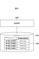
- the control device 600 includes a memory storing operation history data 620 for managing the frequency of operation of each of the first power converter 310 to the fourth power converter 340. 630.
- the operation history data 620 represents the cumulative operating period length, which is the cumulative value of the period length during which the power converter is in the operating state, for each of the first power converter 310 to the fourth power converter 340 .
- FIG. 7 shows a flowchart of heat generation suppression processing according to this embodiment. Only differences between the heat generation suppression process shown in FIG. 7 and the heat generation suppression process shown in FIG. 3 will be described below.
- the control device 600 determines that the required power value WX is equal to or less than the first threshold value W1 predetermined as the upper limit value of the power that can be output by one operating power converter (step S12; YES).
- step S12 the first threshold value W1 predetermined as the upper limit value of the power that can be output by one operating power converter.
- the control device 600 uses the operation history data 620, under the condition that the variation in the dispersion of the operation period length among the four power converters 310 to 340 is minimal, Select one as the active power converter. Specifically, the power converter with the shortest cumulative operating period length is selected as the operating power converter among the four units. Then, the selected operating power converter is controlled to be in the operating state, and the remaining three non-operating power converters are controlled to be in the non-operating state (step S21).
- control device 600 sets the required power value WX to be greater than the second threshold value W2 (step S14; NO), and preliminarily sets the upper limit value of the power that can be output by the three operating power converters. If it is equal to or less than the determined third threshold value W3 (step S16; YES), first, using the operation history data 620, the operation period length between the four units of the first power converter 310 to the fourth power converter 340 3 out of the 4 are selected as active power converters under the condition that the change in the variance of is minimal. Then, the selected three operating power converters are controlled to be in the operating state, and the remaining one non-operating power converter is controlled to be in the non-operating state (step S23).
- control device 600 updates the operation history data 620 (step S24) after step S21, S22, S23, or S18. That is, the control device 600 according to this embodiment updates the operation history data 620 each time the number of machines is controlled. Therefore, the latest operation history data 620 can be used in the next number control.
- step S24 the control device 600 according to the present embodiment refers to the updated operation history data 620, and the operation period length of at least one of the first power converter 310 to the fourth power converter 340 is It is checked whether or not a predetermined reference period length has been exceeded. Then, when there is a power conversion device whose operating period length exceeds the reference period length, the control device 600 issues a warning to that effect to the outside.
- exital specifically includes a terminal placed in a remote management center that manages the operation of the display device 800, a warning light attached to the display device 800, and other devices for informing maintenance personnel of warnings.
- Means notification means specifically includes a terminal placed in a remote management center that manages the operation of the display device 800, a warning light attached to the display device 800, and other devices for informing maintenance personnel of warnings.
- Means notification means specifically includes a terminal placed in a remote management center that manages the operation of the display device 800, a warning light attached to the display device 800, and other devices for informing maintenance personnel of warnings.
- control device 600 proceeds to step S19 described above.
- the upper limit value of the brightness of the display screen 100a may be changed according to the time zone of the day. A specific example will be described below.
- the control device 600 first determines whether or not a brightness change time predetermined as a time to change the brightness of the display screen 100a has arrived (step S31).
- the brightness change times are 5:00 am, 10:00 am, 3:00 pm, and 7:00 pm.
- “early morning” refers to the period from 5:00 am to 10:00 am.
- “Daytime” refers to the period from 10:00 am to 3:00 pm.
- “Evening” refers to the period from 3:00 pm to 7:00 pm.
- “Night” refers to the period from 7:00 pm to 5:00 am.
- the illuminance of the sunlight is lower at night than in the daytime, so the contrast of the display screen 100a is increased and the display screen 100a is easier to see. Therefore, at night, the brightness of the display screen 100a may be lowered.
- step S31 when nighttime arrives, that is, when 7:00 pm as the brightness change time arrives in step S31 (step S31; YES), the control device 600 sets the upper limit value of the brightness of all the pixels of the display screen 100a to , to a value that is 60% lower than the upper limit value for daytime (step S32).
- control device 600 can set any brightness value represented by the video data under the condition that the instantaneous value of the brightness of each pixel is reduced by 60% compared to the daytime. is corrected to a value that is 60% lower than that in the daytime.
- the display screen 100a is easier to see in the early morning and evening than in the daytime, the brightness of the display screen 100a can be suppressed.
- step S31 when early morning or evening arrives, that is, when 5:00 am or 7:00 pm as the brightness change time arrives in step S31 (step S31; YES), the control device 600 controls all pixels of the display screen 100a. is changed to a value that is 40% lower than the upper limit value for daytime (step S32).
- control device 600 can reduce the instantaneous value of the brightness of each pixel by 40% compared to the daytime.
- the brightness value is corrected to a value that is 40% lower than that in the daytime.
- control device 600 ends the display of the image on the display device 100 (step S19; YES)
- the heat generation suppression process ends.
- control device 600 continues to display the image on display 100 (step S19; NO)
- control device 600 returns to step S31 and repeats the same processing.
- the control device 600 changes the upper limit value of the brightness of the display screen 100a according to the time period of the day. As a result, the power consumption in the display device 100 can be reduced, and heat generation in the power supply circuit 300 can be further suppressed.
- Embodiments 1-4 have been described above. Variations described below are also possible.
- the display device 800 is installed near a road and displays road information. , advertisements, etc. may be displayed.
- FIG. 1 illustrates a configuration in which the display 100 and the device housing box 710 are separated, but the display 100, the power supply unit 200, the power supply circuit 300, the switch group 400, the repeater 500, and the control device 600 may be contained within a common frame.
- the frame rate of the moving image to be displayed on the display screen 100a was exemplified as the frame rate of the moving image to be displayed on the display screen 100a, but the values are not limited to these values.
- the frame rate may be 24 Hz or higher, specifically 24 Hz, 30 Hz, 50 Hz, or 60 Hz.
- the repetition frequency of the number control is equal to the frame rate of the moving image
- the repetition frequency and the frame rate of the number control may not necessarily be equal.
- the number control may be repeatedly performed at a repetition frequency expressed by f/n.
- the configuration of the voltage drop unit 510 shown in FIG. 2 is not particularly limited.
- the voltage drop unit 510 may be configured by one or more direct current/DC converters (DC to DC converters) or other voltage drop circuits including transformers.
- DC to DC converters DC to DC converters
- each voltage drop circuit can be made lighter than when the voltage drop section 510 is composed of a single voltage drop circuit.
- a plurality of voltage drop circuits can be arranged separately. Therefore, it is possible to avoid concentration of the load of the voltage drop portion 510 on a narrow region. Therefore, the member supporting the voltage drop portion 510 does not need to be formed with high rigidity, so that the weight of the member supporting the voltage drop portion 510 can be reduced.
- the repeater 500 does not have to include the voltage drop section 510 . That is, the repeater 500 may supply the direct-current voltage output from the power supply circuit 300 to the display device 100 as it is. When the repeater 500 does not include the voltage drop section 510, the weight of the repeater 500 can be reduced.
- the light-emitting device included in the display 100 is a light-emitting diode was exemplified, but the light-emitting device may emit visible light from an element that produces organic electroluminescence.
Landscapes
- Engineering & Computer Science (AREA)
- Devices For Indicating Variable Information By Combining Individual Elements (AREA)
- Physics & Mathematics (AREA)
- Computer Hardware Design (AREA)
- General Physics & Mathematics (AREA)
- Theoretical Computer Science (AREA)
- Road Signs Or Road Markings (AREA)
- Transforming Electric Information Into Light Information (AREA)
- Controls And Circuits For Display Device (AREA)
- Direct Current Feeding And Distribution (AREA)
- Control Of Indicators Other Than Cathode Ray Tubes (AREA)
Priority Applications (2)
| Application Number | Priority Date | Filing Date | Title |
|---|---|---|---|
| JP2022579212A JP7450774B2 (ja) | 2021-02-03 | 2021-02-03 | 表示装置 |
| PCT/JP2021/003912 WO2022168200A1 (ja) | 2021-02-03 | 2021-02-03 | 表示装置 |
Applications Claiming Priority (1)
| Application Number | Priority Date | Filing Date | Title |
|---|---|---|---|
| PCT/JP2021/003912 WO2022168200A1 (ja) | 2021-02-03 | 2021-02-03 | 表示装置 |
Publications (1)
| Publication Number | Publication Date |
|---|---|
| WO2022168200A1 true WO2022168200A1 (ja) | 2022-08-11 |
Family
ID=82741265
Family Applications (1)
| Application Number | Title | Priority Date | Filing Date |
|---|---|---|---|
| PCT/JP2021/003912 Ceased WO2022168200A1 (ja) | 2021-02-03 | 2021-02-03 | 表示装置 |
Country Status (2)
| Country | Link |
|---|---|
| JP (1) | JP7450774B2 (https=) |
| WO (1) | WO2022168200A1 (https=) |
Citations (9)
| Publication number | Priority date | Publication date | Assignee | Title |
|---|---|---|---|---|
| JP2001197731A (ja) * | 2000-01-05 | 2001-07-19 | Internatl Business Mach Corp <Ibm> | 電源装置及びコンピュータ |
| JP2001265278A (ja) * | 2000-03-17 | 2001-09-28 | Fujitsu General Ltd | マルチプラズマディスプレイ装置 |
| JP2005062537A (ja) * | 2003-08-14 | 2005-03-10 | Sony Corp | 情報処理装置および方法、プログラム、並びに記録媒体 |
| JP2008186668A (ja) * | 2007-01-29 | 2008-08-14 | Sharp Corp | Led駆動回路およびそれを用いた映像表示装置 |
| JP2008309948A (ja) * | 2007-06-13 | 2008-12-25 | Sharp Corp | 電子機器 |
| JP2010107805A (ja) * | 2008-10-31 | 2010-05-13 | Koyo Electronics Ind Co Ltd | 表示画面付き電子装置 |
| JP2011254604A (ja) * | 2010-06-01 | 2011-12-15 | Nec Computertechno Ltd | 電源ユニットの電力制御装置及びその方法 |
| JP2017120412A (ja) * | 2015-12-28 | 2017-07-06 | 株式会社半導体エネルギー研究所 | 装置、テレビジョンシステム及び電子機器 |
| US20170309232A1 (en) * | 2016-04-21 | 2017-10-26 | Samsung Electronics Co., Ltd. | Power supply device, display apparatus having the same and method for power supply |
-
2021
- 2021-02-03 JP JP2022579212A patent/JP7450774B2/ja active Active
- 2021-02-03 WO PCT/JP2021/003912 patent/WO2022168200A1/ja not_active Ceased
Patent Citations (9)
| Publication number | Priority date | Publication date | Assignee | Title |
|---|---|---|---|---|
| JP2001197731A (ja) * | 2000-01-05 | 2001-07-19 | Internatl Business Mach Corp <Ibm> | 電源装置及びコンピュータ |
| JP2001265278A (ja) * | 2000-03-17 | 2001-09-28 | Fujitsu General Ltd | マルチプラズマディスプレイ装置 |
| JP2005062537A (ja) * | 2003-08-14 | 2005-03-10 | Sony Corp | 情報処理装置および方法、プログラム、並びに記録媒体 |
| JP2008186668A (ja) * | 2007-01-29 | 2008-08-14 | Sharp Corp | Led駆動回路およびそれを用いた映像表示装置 |
| JP2008309948A (ja) * | 2007-06-13 | 2008-12-25 | Sharp Corp | 電子機器 |
| JP2010107805A (ja) * | 2008-10-31 | 2010-05-13 | Koyo Electronics Ind Co Ltd | 表示画面付き電子装置 |
| JP2011254604A (ja) * | 2010-06-01 | 2011-12-15 | Nec Computertechno Ltd | 電源ユニットの電力制御装置及びその方法 |
| JP2017120412A (ja) * | 2015-12-28 | 2017-07-06 | 株式会社半導体エネルギー研究所 | 装置、テレビジョンシステム及び電子機器 |
| US20170309232A1 (en) * | 2016-04-21 | 2017-10-26 | Samsung Electronics Co., Ltd. | Power supply device, display apparatus having the same and method for power supply |
Also Published As
| Publication number | Publication date |
|---|---|
| JPWO2022168200A1 (https=) | 2022-08-11 |
| JP7450774B2 (ja) | 2024-03-15 |
Similar Documents
| Publication | Publication Date | Title |
|---|---|---|
| KR101903703B1 (ko) | Dc-dc 컨버터 및 이를 포함한 유기전계발광 표시장치 | |
| US10907778B2 (en) | LED apparatus with integrated power supply and a method of employing same | |
| KR20130072175A (ko) | 백라이트 모듈과 그 구동 방법 및 이를 이용하는 디스플레이 장치 | |
| KR102755406B1 (ko) | 저전위 단 스위치 제어에 기반한 led 백라이트 구동 회로의 구동 방법 | |
| KR20150005246A (ko) | 유기전계발광 표시장치 및 그의 구동방법 | |
| KR100948057B1 (ko) | 절전형 엘이디 전광판 시스템 | |
| KR102050518B1 (ko) | 표시 장치의 전력 제어 장치 및 방법 | |
| JP7450774B2 (ja) | 表示装置 | |
| CN111599319B (zh) | 背光驱动电路、方法及显示设备 | |
| JP2010117682A (ja) | 表示装置 | |
| KR102745537B1 (ko) | 표시장치 | |
| JP4907068B2 (ja) | 画像表示装置 | |
| JP2014240854A (ja) | 液晶表示装置およびテレビジョン装置 | |
| JP2013089777A (ja) | 発光素子駆動装置 | |
| JP4129878B2 (ja) | 液晶表示装置のランプ駆動装置 | |
| JP2017530524A (ja) | 液晶表示手段に用いるledバックライト源及び液晶表示手段 | |
| US8344664B2 (en) | Power saving light emitting diode display board system | |
| CN218217742U (zh) | Led控制电路及led灯 | |
| KR20110036723A (ko) | 저전력 구동 엘이디 전광판 | |
| US20140118323A1 (en) | Organic light emitting display | |
| EP3736802A1 (en) | Light-emitting device and display equipment related to variable operation voltage used for reducing power consumption | |
| EP2364066A1 (en) | Display device and guide lamp including same | |
| US11289008B2 (en) | Pixel circuit | |
| US20060022610A1 (en) | Incremental distributed driver | |
| KR101011970B1 (ko) | 엘이디 램프용 모듈형 직류전원 공급장치 |
Legal Events
| Date | Code | Title | Description |
|---|---|---|---|
| 121 | Ep: the epo has been informed by wipo that ep was designated in this application |
Ref document number: 21924597 Country of ref document: EP Kind code of ref document: A1 |
|
| ENP | Entry into the national phase |
Ref document number: 2022579212 Country of ref document: JP Kind code of ref document: A |
|
| NENP | Non-entry into the national phase |
Ref country code: DE |
|
| 122 | Ep: pct application non-entry in european phase |
Ref document number: 21924597 Country of ref document: EP Kind code of ref document: A1 |